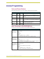
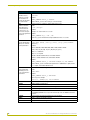
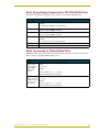
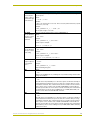
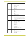
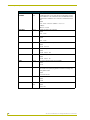
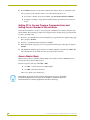
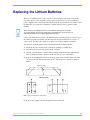
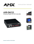
1
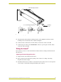
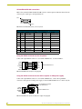
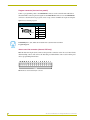
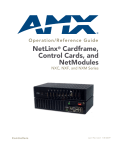
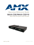
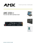
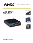
instruction manual
3
Axcent
and
3
Axcent Pro
Integrated Axcess Controllers
A x c e s s C e n t ra l C o n t r o l l e r s
AMX Limited Warranty and Disclaimer
AMX Corporation warrants its products to be free of defects in material and workmanship under normal use for three
(3) years from the date of purchase from AMX Corporation, with the following exceptions:
•
Electroluminescent and LCD Control Panels are warranted for three (3) years, except for the display and touch
overlay components that are warranted for a period of one (1) year.
•
Disk drive mechanisms, pan/tilt heads, power supplies, and MX Series products are warranted for a period of one
(1) year.
•
AMX Lighting products are guaranteed to switch on and off any load that is properly connected to our lighting
products, as long as the AMX Lighting products are under warranty. AMX Corporation does guarantee the
control of dimmable loads that are properly connected to our lighting products. The dimming performance or
quality cannot be guaranteed due to the random combinations of dimmers, lamps and ballasts or transformers.
•
Unless otherwise specified, OEM and custom products are warranted for a period of one (1) year.
•
AMX Software is warranted for a period of ninety (90) days.
•
Batteries and incandescent lamps are not covered under the warranty.
This warranty extends only to products purchased directly from AMX Corporation or an Authorized AMX Dealer.
All products returned to AMX require a Return Material Authorization (RMA) number. The RMA number is
obtained from the AMX RMA Department. The RMA number must be clearly marked on the outside of each box.
The RMA is valid for a 30-day period. After the 30-day period the RMA will be cancelled. Any shipments received
not consistent with the RMA, or after the RMA is cancelled, will be refused. AMX is not responsible for products
returned without a valid RMA number.
AMX Corporation is not liable for any damages caused by its products or for the failure of its products to perform.
This includes any lost profits, lost savings, incidental damages, or consequential damages. AMX Corporation is not
liable for any claim made by a third party or by an AMX Dealer for a third party.
This limitation of liability applies whether damages are sought, or a claim is made, under this warranty or as a tort
claim (including negligence and strict product liability), a contract claim, or any other claim. This limitation of
liability cannot be waived or amended by any person. This limitation of liability will be effective even if AMX Corporation or an authorized representative of AMX Corporation has been advised of the possibility of any such damages.
This limitation of liability, however, will not apply to claims for personal injury.
Some states do not allow a limitation of how long an implied warranty last. Some states do not allow the limitation or
exclusion of incidental or consequential damages for consumer products. In such states, the limitation or exclusion of
the Limited Warranty may not apply. This Limited Warranty gives the owner specific legal rights. The owner may
also have other rights that vary from state to state. The owner is advised to consult applicable state laws for full
determination of rights.
EXCEPT AS EXPRESSLY SET FORTH IN THIS WARRANTY, AMX CORPORATION MAKES NO
OTHER WARRANTIES, EXPRESSED OR IMPLIED, INCLUDING ANY IMPLIED WARRANTIES OF
MERCHANTABILITY OR FITNESS FOR A PARTICULAR PURPOSE. AMX CORPORATION
EXPRESSLY DISCLAIMS ALL WARRANTIES NOT STATED IN THIS LIMITED WARRANTY. ANY
IMPLIED WARRANTIES THAT MAY BE IMPOSED BY LAW ARE LIMITED TO THE TERMS OF THIS
LIMITED WARRANTY.
Table of Contents
Table of Contents
Product Information .................................................................................................1
Specifications .................................................................................................................... 1
Installation .................................................................................................................3
Installing Axcess Control Cards (Axcent3 Pro Only) ......................................................... 3
Installing the Axcent3 into an Equipment Rack ................................................................. 3
Installing the AC-RK3 Rack Kit.......................................................................................... 3
Installing the CSB Cable Support Bracket......................................................................... 4
Wiring the Axcent3 ............................................................................................................ 5
Preparing and connecting captive wires .................................................................................. 5
RS-232/RS-422/RS-485 connections ...................................................................................... 6
Using the AXlink connector for data and power ....................................................................... 6
Using the AXlink connector for data with a separate 12 VDC power supply............................ 6
Relay connections.................................................................................................................... 7
IR/SERIAL/DATA connections ................................................................................................. 7
Input/Output connections ......................................................................................................... 7
Program connector (front and rear panels) .............................................................................. 8
Axcess card slot connector (Axcent3 PRO only) ..................................................................... 8
Axcess Programming ...............................................................................................9
Device and Channel Numbers .......................................................................................... 9
Send_Commands for RS-232/422/485 Ports.................................................................... 9
Send_String Escape Sequences for RS-232/422/485 Ports........................................... 11
Send_Commands for IR/Serial/Data Ports...................................................................... 11
Send_Commands for Input/Output Ports ........................................................................ 16
Standard IR Function Order ............................................................................................ 17
Program Port Commands................................................................................................ 18
Xmodem Timing Commands........................................................................................... 21
Setting PC-to-Axcess Program Communications, and a Controller’s Device Number in Terminal Emulator Mode ....................................................................................................... 21
Setting PC to Axcess Program Communications and
Setting Device Number in Normal Mode...................................................................... 22
Axcess Master Mode....................................................................................................... 22
Replacing the Lithium Batteries ............................................................................25
Updating Firmware .................................................................................................27
Configuration ................................................................................................................... 27
Downloading Firmware.................................................................................................... 27
Axcent3 and Axcent3 Pro Integrated Axcess Controllers
i
Table of Contents
ii
Axcent3 and Axcent3 Pro Integrated Axcess Controllers
Product Information
Product Information
The Axcent3 and Axcent3 Pro Integrated Axcess Controllers are multi-port Central Controllers that
can be programmed to control RS-232/422/485, relay, IR/serial/data, and input/output devices. The
Axcent3 Pro combines the multi-port functionality with 4 card slots that can be populated with
Axcess Central Controller cards to accommodate system growth.
Specifications
The following table lists the specifications for the Axcent3 and Axcent3 Pro.
Specifications
Dimensions (HWD):
Axcent3
Axcent3
3.47" x 17.0" x 3.0" (88.1 mm x 432 mm x 76.2 mm)
Pro
3.47" x 17.0" x 13.65" (88.1 mm x 432 mm x 356.8 mm)
Weight:
Axcent3
3
Axcent Pro
2.5 lbs (1.1 kg)
5.6 lbs (2.6 kg) without Axcess Control Cards
Power Requirement:
Axcent3
3
Axcent Pro
Memory:
• 500 mA @ 12 VDC (all relays energized)
• 550 mA @ 12 VDC (without Axcess control cards) (all relays energized)
• Volatile memory: 128Kbx16 (user-modifiable)
• Non-volatile memory: 256Kbx16 (user-modifiable)
Enclosure
Metal with black matte finish
Input buffer
128 bytes
Output buffer (AXlink)
128 bytes
Supported baud rates
300, 600, 1200, 2400, 4800, 9600, 19200, 38400
Max. length of
SEND_STRING to device
64
Max. Length of data packets
from device
64
Front Panel Components:
PROGRAM port
DB-9 (male) connector for system programming
Status indicators
32 red LEDs showing port activity:
• RS-232/422/485 - 6 receive LEDs and 6 transmit LEDs
• Relay - 8 LEDs
• IR/Serial/Data - 6 LEDs
• I/O - 6 LEDs
AXlink indicator
Green LED shows AXlink data activity. Blink patterns include:
• Off - No power, or the controller is not functioning properly
• 1 blink per second - Normal operation. Device numbers match the
programmed device numbers in the Axcess program.
• 2 blinks per second - Device numbers do not match the Axcess program,
a device is not present, or a device is not set to the right number.
• 3 blinks per second - AXlink bus error. Check all AXlink bus connections.
• Full On - Axcess program is not present and there is no AXlink activity
Slots 1 - 4
RS-232 Range:
4 Axcess Control Card slots (Axcent3 Pro only)
50’ (15.24 m) max.
Axcent3 and Axcent3 Pro Integrated Axcess Controllers
1
Product Information
Specifications (Cont.)
Rear Panel Components:
RS-232/RS-422/RS-485
ports
Six 9-pin (male) D-sub, RS-232/422/485 XON/XOFF, CTS/RTS, 300, 200 baud
Status indicators
32 red LEDs that show RS-232/422/485, relay, IR/Serial/Data, and I/O port
activity. The LEDs light when data activity occurs on the associated ports.
AXlink indicator
Green LED showing power and AXlink data activity.
AXlink/PWR connector
4-pin connector for AXlink data and power, and 2-pin connector for external
12 VDC power supply
RELAYS connector
Two 8-pin connectors, 750 mA, 28 VAC/24 VDC (normally open)
IR/SERIAL/DATA
connectors
12-pin (6 two-pins) male connector that supports IR, IR/Serial or one-way data
communication (0 - 5 VDC levels only)
Input/Output connectors
8-pin connector, I/O 1 - 6, Common, +12 VDC power tap 200 mA, contact
closure or TTL logic inputs
PROGRAM port
DB-9 (male) connector for system programming and diagnostics
Slots 1 - 4
Four 16-pin connectors for Axcess Control Cards (Axcent3 Pro only)
Included Accessories:
• 4 CC-IRC emitters
• Metal tab strip for commoning relays
• Rack-mount brackets
Optional Accessories:
• 12 VDC power supply
• CSB Cable Support Bracket
• AC-RK3 Rack Kit
• Axcess Control Cards (Axcent3 Pro only)
2
Axcent3 and Axcent3 Pro Integrated Axcess Controllers
Installation
Installation
Installing Axcess Control Cards (Axcent3 Pro Only)
To install Axcess Control Cards:
1. Discharge the static electricity from your body, by touching a grounded object.
2. Remove the thumbscrews and faceplate from the front panel (FIG. 1).
Removable faceplate
RS-232 / 422 / 485
RELAYS
IR / SERIAL
DATA
TX
1
2
3
1
2
3
I/O
4
5
6
1
2
3
4
1
2
3
1
2
3
4
5
6
5
6
7
8
4
5
6
4
5
6
RX
AXlink
PROGRAM
Thumbscrews
FIG. 1 Axcent3 Pro
3. Install up to 4 Axcess Control Cards component-side up into SLOT 1 - SLOT 4.
4. Replace the faceplate and secure with the thumbscrews.
Installing the Axcent3 into an Equipment Rack
Use the rack-mounting brackets supplied with each controller for equipment rack installations.
Remove the mounting brackets for flat surface installations.
1. Discharge the static electricity from your body by touching a grounded object.
2. Place the controller into the equipment rack, and align the mounting bracket holes with the
mounting holes on the equipment rack. Start the mounting screws on both sides of the
controller and tighten.
3. Connect the data cables into the controller.
4. Connect the power cable to the AXLINK/PWR connector to power-up the controller.
Installing the AC-RK3 Rack Kit
Use the optional AC-RK3 Rack Kit for rear equipment rack rail installations or to place the
controller 6 inches from the front/rear of the equipment rack. You need a Phillips-head screwdriver.
1. Discharge the static electricity from your body by touching a grounded object.
2. Remove the rack-mount brackets supplied with the controller.
3. Install the AC-RK3 brackets with the supplied Phillips-head screws. Align the bracket holes
with the mounting brackets on the equipment rack. Then, start the mounting screws on both
sides of the controller and tighten (see FIG. 2).
Axcent3 and Axcent3 Pro Integrated Axcess Controllers
3
Installation
Mounting
screw holes
AC-RK3 Rack Kit
mounting brackets
Mounting Configurations
Front
Front
FIG. 2 AC-RK3 Rack Kit mounting diagram
4. Connect the data cables into the controller.
5. Connect the power cable to the AXLINK/PWR connector to power-up the controller.
Installing the CSB Cable Support Bracket
Install the optional CSB Cable Support Bracket to secure the power and data cables connected to
the controller. You can use the CSB with the supplied rack mounting brackets or optional AC-RK3.
You need a Phillips-head screwdriver.
1. Discharge the static electricity from you body by touching a grounded object.
2. Disconnect all (if applicable) power and data cables from the controller.
3. Hold the controller in place, and remove the mounting hardware from the equipment rack.
Then, carefully remove the controller from the rack and place it onto a flat surface.
4. Install the CSB, as shown in FIG. 3.
4
Axcent3 and Axcent3 Pro Integrated Axcess Controllers
Installation
CSB Cable Support Bracket
Mounting
screws
2", 4", 6" Mounting Configurations
2"
4"
6"
Mounting
screws
FIG. 3 CSB mounting diagram
5. Align the bracket holes with the mounting brackets on the equipment rack. Then, start the
mounting screws on both sides of the controller and tighten.
6. Connect the data cables into the controller. Then, secure the data cables to the CSB.
7. Connect the power cable to the AXLINK/PWR connector to power-up the controller. Then,
secure the cable to the CSB.
Wiring the Axcent3
Each connector you use to control external devices must be wired according to the information in
this subsection.
Preparing and connecting captive wires
1. Strip 0.25 inch of wire insulation off all wires.
2. Insert each wire into the appropriate opening on the connector according to the wiring
diagrams and connector types.
3. Turn the flat-head screws clockwise to secure the wire in the connector. Do not over-torque the
screw; doing so can bend the seating pin and damage the connector.
Axcent3 and Axcent3 Pro Integrated Axcess Controllers
5
Installation
RS-232/RS-422/RS-485 connections
FIG. 4 shows the RS-232/RS-422/RS-485 DB-9 (male) connector pinouts. The table below lists the
connector pins, signal types, and signal functions.
Pin 1
Pin 9
FIG. 4 RS-232/422/485 DB-9 (male) connector pinouts
DB-9 Pinouts
Wiring and Baud Configurations
Pin
RS-232
Signal
Function
1
RX-
Receive data
2
RXD
Receive data
X
3
TXD
Transmit data
X
4
TX+
Transmit data
5
GND
Signal ground
6
RX+
Receive data
RS-422
X
7
RTS
Request to send
X
8
CTS
Clear to send
X
9
TX-
Transmit data
RS-485
X
X (strap to pin 9)
X
X (strap to pin 6)
X
X
X (strap to pin 4)
X
X (strap to pin 1)
The X’s show where to terminate the wires on the DB-9 connector.
Using the AXlink connector for data and power
Connect the 4-pin AXlink connector to an external AXlink device, as shown in FIG. 5.
PWR+
PWR+
AXP
AXP/TX
AXM/RX
AXM
GND-
GND-
External AXlink device
AXlink/PWR connector
FIG. 5 AXlink/PWR data and power wiring diagram
Using the AXlink connector for data with a separate 12 VDC power supply
Connect the 4-pin AXlink connector to an external AXlink device; connect the 2-pin PWR
connector to the separate 12 VDC power supply as shown in FIG. 6. Make sure to connect only the
PWR+
GNDPWR+
AXP/TX
AXM/RX
GND-
PWR+
AXP
AXM
GND-
Local 12 VDC power supply
for ext. AXlink device
External AXlink device
Axcent3
FIG. 6 AXlink/PWR and optional 12 VDC power supply wiring diagram
6
Axcent3 and Axcent3 Pro Integrated Axcess Controllers
Installation
GND wire on the AXlink/PWR connector when using a separate 12 VDC power supply. Do not
connect the PWR wire to the AXlink connector’s PWR (+) opening.
Relay connections
Connect up to eight independent external relay devices to the 16-pin RELAYS connector. Use A for
common and B for output. Each relay is isolated and normally open. A metal connector strip is also
provided to common multiple relays.
7
8
A
B
6
A
B
5
A
B
3
4
A
B
B
A
B
2
A
B
1
A
B
A
RELAYS
FIG. 7 RELAY 16-pin connector
IR/SERIAL/DATA connections
Connect up to six IR, IR/Serial, and/or DATA (transmit only, 0 - 5 VDC levels only) devices to the
12-pin IR/SERIAL/DATA connector shown in FIG. 8. You can connect a CC-IRC Infrared Emitter,
external serial device with a 2-pin captive-wire. You can also connect a data 0 - 5 VDC device.
6
5
4
3
2
1
IR / SERIAL / DATA
FIG. 8 IR/SERIAL/DATA 12-pin connector
Input/Output connections
GND
I/O1
I/O2
I/O3
I/O4
I/O5
12V
I/O6
Connect up to six Input/Output (I/O) devices to the INPUT/OUTPUT 8-pin connector, as shown in
INPUT/OUTPUT 8-pin (male) connector section on page 7. A contact closure between GND and
an I/O port is detected as a PUSH. When used for a voltage input, the I/O port detects a low (0 - 1.5
VDC) as a PUSH, and a high signal (3.5 - 5 VDC) as a RELEASE. When used for an output, each
I/O port acts as a switch to GND and is rated at 200 mA @ 12 VDC.
INPUT / OUTPUT
FIG. 9 INPUT/OUTPUT 8-pin (male) connector
+12V - 12 VDC power output for PCS Power Current Sensors, VSS2 Video Sync
Sensors, or similar I/O-type equipment
I/O 1 - 6 - Six I/O ports
GND - Common ground shared with I/O ports 1 - 6
Axcent3 and Axcent3 Pro Integrated Axcess Controllers
7
Installation
Program connector (front and rear panels)
Connect a programming cable to the PROGRAM connector on the controller. The table below
shows the DB-9 connector pins and signals for the PROGRAM connector. Use the PROGRAM
connector to download Axcess programs, and to set up control communication options using the
OpenAxcess software program.
Program Connector and Pinouts
Pin 1
Pin 9
Pin
Signal
2
RXD
3
TXD
4
+12 VDC
5
GND
7
+12 VDC
PROGRAM pins 1, 6, 8, and 9 are not used. Pins 4, 5, and 7 are for an ALF
Programming Unit.
Axcess card slot connector (Axcent3 PRO only)
FIG. 10 shows the 16-pin (male) connector that provides connection to the Axcess Control Cards.
After installing control cards, refer to the literature provided with the control card for wiring and
Axcess programming information.
SLOT 4
FIG. 10 Axcess Control Card 16-pin connector
8
Axcent3 and Axcent3 Pro Integrated Axcess Controllers
Axcess Programming
Axcess Programming
Device and Channel Numbers
The following table lists the port type, device numbers, channels, with a brief description.
Device and Channel Number Parameters
Port Type
Device
Numbers
Channels
Description
RS-232/422/485
1-6
1 - 255
6 Rs-232/422/485 control ports with XON/XOFF(transmit on/
transmit off), and CTS/RTS (clear to send/ready to send), 300,
200 baud.
Relay
7
1-8
8-channel relay ports
IR/Serial/Data
8 - 13
1 - 254
6 IR/Serial/Data control ports that support high-frequency carriers up to 1.14 MHz, and one-way data, 300 - 38,400 baud (0 - 5
VDC)
Input/Output
14
1-6
6-channel I/O port for contact closure, 0 - 5 VDC voltage sensing,
or interactive power sensing for IR ports
Axcess Control
Cards
15 - 18
Card
dependent
Card slots 1 - 4 (Axcent3 Pro only)
Send_Commands for RS-232/422/485 Ports
The table below lists the Send_Commands for the internal RS-232/422/485 ports.
Send_Commands for RS-232/422/485 Mode
B9MOFF
Sets the port’s communication parameters.
Sets the parameters for stop and data bits according to the software settings on the RS232 port (default).
Syntax:
’B9MOFF’
Example:
SEND_COMMAND RS232_1,’B9MOFF’
Sets the RS-232 port settings to match the port’s configuration settings.
B9MON
Overrides the communication settings
on the RS-232 port.
Overrides settings to 9 data bits and 1 stop bit, and use the port’s active baud rate settings.
Example:
SEND_COMMAND RS232_1,’B9MON’
Resets the RS-232 port’s communication parameters to 9 data bits, 1 stop bit, and
locks-in the baud rate set with the OpenAxcess software program.
CHARD
Sets the delay time
between transmitted
characters.
Syntax:
’CHARD-<0-255>’
Variables:
<0 - 255> = time in 100 microsecond increments
Example:
SEND_COMMAND RS232_1,’CHARD-100’
Sets 10 millisecond delay between all transmitted characters.
Axcent3 and Axcent3 Pro Integrated Axcess Controllers
9
Axcess Programming
Send_Commands for RS-232/422/485 Mode (Cont.)
CTSPSH
Enables Pushes,
Releases, and status information to
send to the Program
via channel 255.
Syntax:
’CTSPSH’
Example:
SEND_COMMAND RS232_1,’CTSPSH’
Sets the RS232_1 port to detect changes on the CTS input.
DE
A contact closure is sometimes called a debouncing circuit.
Sets the minimum
delay time before
controller detects/
responds to a contact closure and performs a programmed
operation.
Syntax:
"’DE’,<Delay>"
Variables:
<Delay> = 0 - 255 in tenths of a second
Example:
SEND_COMMAND IR_1,"’DE’, 20"
Sets the IR_1 port’s minimum linked input stabilization time to 2 seconds.
Set Baud
Set the RS-232/422/
485 port’s communication parameters.
Syntax:
’SET BAUD (Baud),(Parity),(Data),(Stop),[485(DISABLE/
ENABLE)]’
Variables:
Baud = 300, 600, 1200, 2400, 4800, 9600, 19200, 38400 or AUTO
Parity = N (none), O (odd), E (even), M (mark), S (space)
Data = 7 or 8 data bits
Stop = 1 or 2 stop bits
Disable = disables RS-485 mode, and enables RS-422
Enable = enables RS-485 mode, and disables RS-422
Example:
SEND_COMMAND RS232_1,’SET BAUD 9600,N,8,1,485 ENABLE’
Sets the RS232_1 port’s communication parameters to 9,600 baud, no parity, 8 data
bits, 1 stop bit, and enables RS-485 mode.
Get Baud
The port sends the data through the master’s PROGRAM port.
Gets the RS-232/
422/485 port’s current communication
parameters.
Syntax:
’GET BAUD’
Example:
SEND_COMMAND RS232_1,’GET BAUD’
System response example:
Device 1, 38400,N,8,1 485 DISABLED
’HSOFF’
Disables hardware handshaking (default).
’HSON’
Enables hardware handshaking.
’RXCLR’
Clears all characters in the receive buffer waiting to be sent to the master.
’RXOFF’
Stops transmitting received characters to the master.
’RXON’
Transmits received characters to the master.
The CREATE_BUFFER Axcess keyword automatically sends the RXON command to
the device.
10
’TXCLR’
Clears and stops all characters waiting in the transmit buffer.
’XOFF’
Disables software handshaking (default).
’XON’
Enables software handshaking.
Axcent3 and Axcent3 Pro Integrated Axcess Controllers
Axcess Programming
Send_String Escape Sequences for RS-232/422/485 Ports
The table below lists the Send_String escape sequences for the RS-232/422/485 ports.
Send_String Escape Sequences for RS-232/422/485 Ports
"27,17,<1-255>"
Sends a break character for the specified length of time.
Variables:
1 - 255 = time in 100 microsecond increments
"27,18,1"
Sets the ninth data bit to 1 for all subsequent characters transmitted. Use this escape
sequence with the ’B9MON’ command.
"27,18,0"
Clears the ninth data bit to 0 for all subsequent characters transmitted. Use this escape
sequence with the ’B9MON’ command.
"27,19,<1-255>"
Inserts delay time before the next character transmits.
Variables:
1 - 255 = time in 1 microsecond increments.
"27,20,0"
Sets RTS hardware handshake’s output high.
"27,20,1"
Sets RTS hardware handshake’s output low.
Send_Commands for IR/Serial/Data Ports
The IR/Serial/Data Send_Commands listed in the table below generate control data for external
device, and also configure the IR/Serial/Data ports.
Send_Commands for the IR/Serial/Data Ports
CAROFF
This command overrides active software settings.
Disables carrier
from responding
until a CARON
command is
received.
Syntax:
’CAROFF’
Example:
SEND_COMMAND IR_1,'CAROFF'
Stops transmitting the IR carrier signal.
CARON
Syntax:
Enables the carrier
to respond according to active software settings.
Example:
’CARON’
SEND_COMMAND IR_1,'CARON'
Starts transmitting the IR carrier signal.
Axcent3 and Axcent3 Pro Integrated Axcess Controllers
11
Axcess Programming
Send_Commands for the IR/Serial/Data Ports (Cont.)
CH
Generates IR digit
pulses to select a
television channel
number.
Channels 1-99 pulse as two digits. Channels 100 and greater, the one-hundredth digit
pulses as 127. If IR function 21 (enter) exists, it follows the IR digit pulses. CTON sets
the pulse length for each digit and CTOF sets the time between each digit or any other
pulse.
Syntax:
"’CH’,<channel>"
Variables:
<channel> = 0 - 199
Example:
SEND_COMMAND IR_1,"'CH',18"
The controller performs the following:
• Transmits IR pulses for 1 (IR code 11) for the time set by CTON.
• Waits for the time set by CTOF.
• Transmits IR pulses for the IR code for 8 (IR code 18) for the time set by CTON.
• Waits for the time set by CTOF. If the IR code for ENTER (IR code 21) is programmed,
steps 5 and 6 are performed.
• Transmits IR pulses for ENTER (IR code 21) for the time set by CTON.
• Waits for the time set by CTOF.
CP
Transmits IR code
pulses and clear all
commands in the
buffer.
This command pulses the actual IR code. Pulse time is set by the CTON and CTOF
commands.
Syntax:
"’CP’,<channel>"
Variables:
<channel> = 0 - 252
Example:
SEND_COMMAND IR_1,"’CP’,2"
Clears pending commands and pulses command number 2.
CTOF
Sets the single IR
pulses off time
between channel
digits and IR
functions.
CTOF sets the time between digits or any other pulse and CTON sets the pulse length
for each digit. This is the time between digits, or pulses, that is associated with an SP
command.
Syntax:
"’CTOF’,<time>"
Variables:
<time> = 0 - 255 in tenths of a second; Time is stored in permanent memory. System
default is 5 (.5 second).
Example:
SEND_COMMAND IR_1, "'CTOF',10"
Sets the channel's off-time pulse in tenths of a second. Default time is 5 (0.5 second).
Time is stored in non-volatile RAM.
12
Axcent3 and Axcent3 Pro Integrated Axcess Controllers
Axcess Programming
Send_Commands for the IR/Serial/Data Ports (Cont.)
CTON
Sets the IR pulse
(single) on time for
each channel digit
and IR functions.
CTON sets the pulse length for each digit and CTOF sets the time between digits or
any other pulse.
Syntax:
"’CTON’,<time>"
Variables:
<time> = 0 - 255 in tenths of a second; Time is stored in permanent memory. System
default is 5 (.5 second).
Example:
SEND_COMMAND IR_1, "'CTON',20"
Sets the pulse length to 2 seconds.
GET BAUD
The port sends the data through the master's PROGRAM port.
Gets the IR/Serial/
Data port's current
communication
parameters.
Syntax:
’GET BAUD’
Example:
SEND_COMMAND IR_1,'GET BAUD'
System response example:
Device 1,38400,N,8,1
GET MODE
Gets the IR/Serial/
Data port's current
mode setting.
Syntax:
’GET MODE’
Example:
SEND_COMMAND IR_1,'GET MODE'
System response example:
Device 8 IR,CARRIER,IO LINK 0
IROFF
Stops IR output on
the designated
device.
Syntax:
’IROFF’
Example:
SEND_COMMAND IR_1,'IROFF'
Stops transmitting IR signals.
POD
Syntax:
’POD’
Disables current PON (power on) or POF (power off) command settings. Channel 255
changes are enabled.
POF
Syntax:
’POF’
Sends IR function 28 (if available) or 9 to turn device power off. After three attempts, if
the linked I/O channel still detects a power-on status, the controller starts processing
stored buffer commands. Then, if another IR function 28 or 9 fails to turn the external
device's power off, the controller sends a PUSH and RELEASE of channel 248 and
generates a power failure error. If the device is turned on manually, this command turns
the external device's power off unless a PON (power on) or POD (disable POF) command is received. Refer to the SET IO LINK command.
PON
Syntax:
’PON’
Sends IR function 27 (if available) or 9 to turn device power on. After three attempts, if
the linked I/O channel still detects a power-off status, the controller starts processing
stored buffer commands. Then, if another IR function 27 or 9 fails to turn the external
device's power on, the controller sends a PUSH and RELEASE of channel 248 and
generates a power failure error. If the device is turned off manually, this command turns
external device power on unless a POF (power off) or POD (disable 'PON' command)
command is received.
Axcent3 and Axcent3 Pro Integrated Axcess Controllers
13
Axcess Programming
Send_Commands for the IR/Serial/Data Ports (Cont.)
PTOF
Sets IR power-off
pulse time after a
power-on pulse in
increments of .10
seconds.
Syntax:
"’PTOF’,<time>"
Variables:
<time> = 0 - 255; Time is stored in permanent memory. System default is 15 (1.5
seconds).
Example:
SEND_COMMAND 55,"'PTOF',15"
Sets the power-off pulse time after a power-on pulse to 1.5 seconds for device 55.
PTON
Syntax:
Sets the IR power"’PTON’,<time>"
on pulse time after
Variables:
a power-off pulse in
<time> = 0 - 255; Time is stored in permanent memory. System default is 15 (1.5
increments of .10
seconds).
seconds.
Example:
SEND_COMMAND 55,"'PTON',15"
Sets the power-off pulse time after a power-on pulse to 1.5 seconds for device 55.
SET BAUD
Syntax:
Sets the IR/Serial/
Data port's
communication
parameters.
Variables:
’SET BAUD (Baud),(Parity),(Data),(Stop)’
Baud = 300 - 38,400
Parity = N (none), O (odd), E (even)
Data = 7 or 8 data bits
Stop = 1 stop bit
Example:
SEND_COMMAND IR_1,'SET BAUD 9600,N,8,1'
Sets the IR_1 port's communication parameters to 9,600 baud, no parity, 8 data bits,
and 1 stop bit.
SET MODE
Sets the IR/Serial/
Data port for IR-,
Serial-, or Datacontrolled devices
that connect to the
port.
Syntax:
’SET MODE (MODE)’
Variables:
Mode = IR, SERIAL, or DATA
Example:
SEND_COMMAND IR_1,'SET MODE IR'
Sets the IR_1 port to IR mode so that an IR-controlled device can be connected to the
port.
SET IO LINK
The I/O channel can sense 0-5 VDC using a PCS or PCS2 Power Current Sensor. Set
the I/O channel to 0 to disable the link function.
Links an IR/Serial/
Syntax:
Data port to an
input/output (I/O)
’SET MODE (MODE)’
channel for use with
Example:
PON and POF
commands.
SEND_COMMAND IR_1,'SET IO LINK 1'
Sets the IR_1 port link to I/O port 1. The IR port uses the specified I/O input as power
status for processing PON and POF commands.
14
Axcent3 and Axcent3 Pro Integrated Axcess Controllers
Axcess Programming
Send_Commands for the IR/Serial/Data Ports (Cont.)
SP
The CTON sets pulse length and CTOF sets time between pulses.
Generates a single
<IR out> function
pulse.
Syntax:
"’SP’,<IR out>"
Variables:
<IR out> = 1 - 127
Example:
SEND_COMMAND IR_1, "'SP',25"
Pulses IR code 25, which decreases the volume level on the equipment connected to
the controller.
XCH
Transmits the IR
code in the format
set with the XCHM
mode command.
Syntax:
’XCH [channel]’
Variables:
<channel> = 0 - 999
Mode 0 (default) Example:
SEND_COMMAND IR_1, 'XCH 3'
Transmits the IR code as 3 enter.
SEND_COMMAND IR_1, 'XCH 34 '
Transmits the IR code as 3 4 enter.
SEND_COMMAND IR_1, 'XCH 343 '
Transmits the IR code as 3 4 3 enter.
Mode 1 Example:
SEND_COMMAND IR_1,'XCH 3'
Transmits the IR code as 0 0 3 enter.
SEND_COMMAND IR_1, 'XCH 34'
Transmits the IR code as 0 3 4 enter.
SEND_COMMAND IR_1,'XCH 343'
Transmits the IR code as 3 4 3 enter.
Mode 2 Example:
SEND_COMMAND IR_1,'XCH 3'
Transmits the IR code as 0 0 3.
SEND_COMMAND IR_1,'XCH 34'
Transmits the IR code as 0 3 4.
SEND_COMMAND IR_1,'XCH 343'
Transmits the IR code as 3 4 3.
Mode 3 Example:
SEND_COMMAND IR_1,'XCH 3'
Transmits the IR code as 0 3.
SEND_COMMAND IR_1,'XCH 34'
Transmits the IR code as 3 4.
SEND_COMMAND IR_1,'XCH 343'
Transmits the IR code as 100 100 100 4 3.
Axcent3 and Axcent3 Pro Integrated Axcess Controllers
15
Axcess Programming
Send_Commands for the IR/Serial/Data Ports (Cont.)
XCHM
Syntax:
Sets the IR output
’XCHM [channel mode]’
format on the chan- Variables:
nel specified with
channel mode = Mode 0 - 3:
the XCH command.
Mode 0: [x][x]<x><enter> (default)
Mode 1: <x><x><x><enter>
Mode 2: <x><x><x>
Mode 3: [[100][100]….]<x><x>
Example:
SEND_COMMAND IR_1,'XCHM-3'
Sets the XCH [Channel] extended channel command to mode 3. Refer to the XCH command for additional programming examples.
Send_Commands for Input/Output Ports
The table below lists the I/O Send_Commands that set the I/O ports on the controller.
Send_Commands for Input/Output Ports
SET INPUT
An active state can be high (logic high) or low (logic low or contact closure). Channel
Sets the input chan- changes, pushes, and releases generate reports based on their active state.
nel's active state.
Syntax:
’SET INPUT (Port) (State)’
Variables:
Port = 1-6
Sate = High or Low
Example:
SEND_COMMAND IO,'SET INPUT 1 HIGH'
Sets I/O port to detect a high state change.
GET INPUT
Gets the input
channel's active
state.
An active state can be high (logic high) or low (logic low or contact closure). Channel
changes, pushes, and releases generate reports based on their active state.
Syntax:
’GET INPUT (Port)’
Variables:
Port = 1-6
Example:
SEND_COMMAND IO,'GET INPUT 1'
Gets I/O port's active state.
16
Axcent3 and Axcent3 Pro Integrated Axcess Controllers
Axcess Programming
Standard IR Function Order
The table below lists the standard function order for IR codes. Refer to the IRLIB instruction
manual to download IR files.
Standard IR Function Order
Function Description
Function Description
1
Play >
22
Channel up or +
2
Stop [ ]
23
Channel down or -
3
Pause | | or still
24
Volume up or +
4
Ffwd >> (AMS/skip/track/
chapter)
25
Volume down or -
5
Rewind << (AMS/skip/track/
chapter)
26
Mute
6
Search fwd >>| (AMS/scan)
27
On (power typically)
7
Search rev |<< (AMS/scan)
28
Off (power typically)
8
Record
29
TV/Video or TV/VCR or TV/LDP
(one button source selection)
9
Power or on/off
30
TV
10
’0’ or ’10’
31
Video1, Line A, VCR1, VDP, or
input +
11
’1’ (channel digits or tracks for
CD)
32
Video2, LineB, VCR2, or input -
12
’2’
33
Video3
13
’3’
34
RGB1 or Tape1
14
’4’
35
RGB2, or Tape2
15
’5’
36
CD
16
’6’
37
Tuner
17
’7’
38
Phono
18
’8’
39
AUX
19
’9’
40
AM/FM
20
’+10’ or ’+100’
41
Play < (play reverse)
21
Enter (used in conjunction
with numbers typically)
42
A/B
Axcent3 and Axcent3 Pro Integrated Axcess Controllers
17
Axcess Programming
Program Port Commands
The PROGRAM port commands listed in the table below perform a wide variety of operations. You
will need to connect an programming cable to the PROGRAM port on a master or slave controller,
and your PC's serial port. The Controllers column shows the commands that can be used with
Central controllers.
PROGRAM Port Commands
Command
Function
Description
COMPARE DEVICE
Master
The controller returns a list of all devices that it detects as missing
from the AXlink bus and then a list of all the extra devices. The controller compares the devices present on the AXlink bus against the
devices listed in the Define_Device section in the controller’s Axcess
program.
Syntax:
COMPARE DEVICE
DATE
Master
The controller returns the current date and day of the week set in the
controller.
Syntax:
DATE
DEVICE STATUS
Master
Syntax:
DEVICE STATUS <Device Number>
The controller returns a list of all activated (on) channels in the specified device.
ECHO OFF
Master and
Slave
Disables terminal character’s echo function.
Syntax:
ECHO OFF
ECHO ON
Master and
Slave
Enables terminal character’s echo function.
Master
The controller reports if it is currently controlling AXlink. The controller stays in control if a valid system program is running, unless there
is another redundant controller present. If the controller is not in control of AXlink, it may not contain a program, there are AXlink wiring
problems, or the backup controller (if present) is in control. The
green LED on the controller also shows indication of AXlink control.
Syntax:
ECHO ON
HAVE CONTROL
Syntax:
HAVE CONTROL
HAVE PROGRAM
Master
The controller reports if it currently has a system program in memory.
Syntax:
HAVE PROGRAM
HELP
Master and
Slave
Displays online help menu.
Syntax:
HELP
LEDON
Master and
Slave
The 32 LEDs will light for approximately two seconds. This command
is used for hardware test purposes.
Syntax:
LEDON
MEMORY
Master
Displays total memory equipped in the controller.
Syntax:
MEMORY
18
Axcent3 and Axcent3 Pro Integrated Axcess Controllers
Axcess Programming
PROGRAM Port Commands (Cont.)
OFF
Master
Turns the device and channel numbers off.
Syntax:
OFF[Device, Channel]
Variables:
Device = 1 - 255
Channel = 1 - 255
Example:
>OFF [52,1]
Turns channel 1 on device 52 off.
ON
Master
Turns the device and channel numbers on.
Syntax:
ON [Device, Channel]
Variables:
Device = 1 - 255
Channel = 1 - 255
Example:
>ON [25,1]
Turns channel 1 on device 25 on.
PASS
Master
Syntax:
PASS <Device Number>
This command communicates across the AXlink bus to external
devices. When the PASS mode is enabled, all characters sent to the
controller are passed along to the specified device, and all characters received from the device travel to the controller and then out of
the card’s port. To exit from the PASS mode, type the following while
holding down the <Shift> key (<ESC> is the Escape key):
++ <Esc> <Esc>
PULSE
Master
Pulse the device and channel numbers.
Syntax:
PULSE [Device, Channel]
Variables:
Device = 1 - 255
Channel = 1 - 255
Example:
>PULSE [16,1]
Pulses channel 1 on device 16.
SEND_COMMAND
Master
Send commands to the specified device. Refer to the device’s literature for programming.
Syntax:
SEND_COMMAND <Device>, String
Variables:
Device = 1 - 255
SEND_STRING
Master
Send strings to the specified device. Refer to the device’s literature
for programming.
Syntax:
SEND_STRING <Device>, String
Variables:
Device = 1 - 255
Axcent3 and Axcent3 Pro Integrated Axcess Controllers
19
Axcess Programming
PROGRAM Port Commands (Cont.)
SET BASE DEVICE
NUMBER
Master and
Slave
Sets the AXlink base device number on the controller’s RS-232 port
1. Subsequent ports on the controller are incrementally set. If the
device number is 1, the controller becomes an AXlink bus master,
and if the device number is set to 2-xxx, the controller becomes a
slave.
Syntax:
SET BASE DEVICE NUMBER <Device>
Variables:
Device = 1 - 238
SET DATE
Master
Changes the date in the controller.
Syntax:
SET DATE
SET TIME
Master
Changes the time in the controller.
Syntax:
SET TIME
SHOW DEVICE
Master
Displays a list of all devices present on the AXlink bus.
Syntax:
SHOW DEVICE
SHOW INPUT OFF
Master
Sets Show Input mode off.
Syntax:
SHOW INPUT OFF
SHOW INPUT ON
Master
Sets Show Input mode on.
Syntax:
SHOW INPUT ON
SLOT
Master
The active controller returns its slot number.
Syntax:
SLOT
SYSTEM RESET
Master
The controller stops communication on AXlink for 2 seconds and
then restarts. The system program then restarts according to the
Define_Start section.
Syntax:
SYSTEM RESET
TIME
Master
The controller returns the time in its internal clock.
Syntax:
TIME
VERSION
Master and
Slave
Displays current software version of the controllers.
Syntax:
VERSION
20
Axcent3 and Axcent3 Pro Integrated Axcess Controllers
Axcess Programming
Xmodem Timing Commands
The table below lists the Axcent3 and Axcent3 Pro Xmodem timing commands. Xmodem timeouts
and retires exist to accommodate potential Ethernet delays and for consistency among and within
products.
Any of the Timeout commands will change timing for Axcess code download as well
as SOFTROM transfer.
Any of the Retry commands will change the number of retries for Axcess code
download as well as SOFTROM transfer.
Xmodem Timing Commands
Xmodem timeouts (Default is 10 sec.)
’TIMEOUT XX’
Via the Program Port.
SEND_COMMAND 0,
’XMTO XX’
Over AXlink, where 0 is the device number.
SEND_COMMAND 1,
’XMTO XX’
Over AXlink, where 1 is the device number.
’RETRY XX’
Via the Program Port.
SEND_COMMAND 0,
’XMRT XX’
Over AXlink, where 0 is the device number.
SEND_COMMAND 1,
’XMRT XX’
Over AXlink, where 1 is the device number.
Where XX is from 1 - 50 seconds in 1-second increments.
Where XX is from 1 - 50 seconds in 1-second increments.
Xmodem retries (Default is 5)
Where XX is from 1 - 10 in increments of 1.
Where XX is from 1 - 10 in increments of 1.
Setting PC-to-Axcess Program Communications, and a
Controller’s Device Number in Terminal Emulator Mode
Follow these instructions to set PC-to-Axcess program communications, and the controller's base
device number. The only time you need to perform these steps is to download an Axcess program
the first time, or to reset a controller back to a master.
1. Connect a programming cable to the PROGRAM connector on the controller, and to the serial
port on your PC.
2. Launch the AxcessX program to open the main window.
3. Press F4 to open the Communications drop-down menu, and select Configure.
4. Press ENTER. Reset the communication parameters so that they match the con-troller's
communication settings. Press F10 to save the new settings and close the CONFIGURE menu .
When AXlink communication is established between the controller and PC, the AX Present
message appears in the lower left-hand corner of the Axcess main window.
You set options in the CONFIGURE window by placing the cursor next to the option
using the directional keys, and pressing Enter. A check mark will appear next to each
option you set.
5. Press F4 again to open the Communications drop-down menu. Choose the Terminal emulator
option to open the Terminal window. You can also press CTRL and T to open the window.
Axcent3 and Axcent3 Pro Integrated Axcess Controllers
21
Axcess Programming
6. Press ENTER four times to lock-in the communication settings. Now, you can download an
Axcess program to the controller. Choose one of the following modes to set:
To reset the controller’s base device number, type SET BASE DEVICE NUMBER 1.
To display everything you type in the Terminal window, type Echo On to activate echo
mode.
Setting PC to Axcess Program Communications and
Setting Device Number in Normal Mode
Follow these instructions to set PC-to-Axcess program communications, and the controller's base
device number. The following procedure is based upon having an existing Axcess program file that
is ready to be downloaded.
1. Press F1 to open the File menu, select Change directory, type the directory path into the popup
dialog and press ENTER.
2. Press F1 to open the File menu and then select OPEN.
3. Enter the file name assigned to your Axcess program in the dialog box that appears and press
ENTER.
4. The defined file will then appear in the Axcess window. Then press F2 and select SEND. The
file loaded into the Axcess window is then sent to the Central controller.
Axcess Master Mode
When an Axcess device is placed in "Master Mode", the Central Controller’s PROGRAM port is
moved to the Axcess device’s RS-232 port.
Press the escape key, then type either MC or MD:
<esc>MC - connects the device in Master Mode
<esc>MD - disconnects the device
where <esc> means "press the Esc key".
Master Mode can be very useful in situations where physical access to the Central
Controller’s PROGRAM port is not practical (for example, in installations where the
Central Controller is located a long distance from the bus device(s)).
22
Axcent3 and Axcent3 Pro Integrated Axcess Controllers
Axcess Programming
Axcent3 and Axcent3 Pro Integrated Axcess Controllers
23
Axcess Programming
24
Axcent3 and Axcent3 Pro Integrated Axcess Controllers
Replacing the Lithium Batteries
Replacing the Lithium Batteries
There are two lithium batteries on the controller’s circuit card with a life of approximately five
years. They protect stored commands against power loss. The batteries are not used when DC
power is supplied to the controller. You should write down the replacement date on a sticker or label
by adding five years to the date of installation, and then attach it to the rear panel for future
reference.
Static electricity can damage electronic circuitry. Before removing the touch panel
circuit card from the enclosure, discharge any accumulated static electricity from your
body and flat-blade tool by touching a grounded metal object.
Contact your dealer before you replace the lithium batteries and verify they have a current copy of
the software program stored in the controller. This will avoid any inadvertent loss of data or a
service outage. To remove the controller’s top panel, you will need a Phillips screwdriver.
You need non-conducting pliers to remove the lithium batteries from the controller.
1. Discharge the static electricity from your body by touching a grounded object.
2. Disconnect all power and data cables from the controller.
3. Hold the controller in place, and remove the mounting hardware from the equipment rack.
Then, carefully remove the controller from the rack and place it on a flat surface.
4. Remove the six Phillips-head screws from the top panel on the controller. Then, remove the
screws from the left and right side of the Axcent3 and Axcent3 Pro controller as shown in
FIG. 11.
Top panel screws
Side panel screws
Axcent3 Controller
Axcent3 Pro Controller
FIG. 11 Top and side panel screw locations
5. Remove the top panel and locate the batteries on the circuit card.
Axcent3 and Axcent3 Pro Integrated Axcess Controllers
25
Replacing the Lithium Batteries
6. Carefully push the lithium battery, located in position B2, out of its socket, and remove with
non-conduction pliers. With the rear of the unit facing you, insert the new battery with the
positive (+) polarity side facing left.
Do not use any type of conductive tools to remove the battery. Doing so will damage
the battery.
7. Plug the AXlink and power connectors back into the AXLINK/PWR connectors on the
controller. Then, remove the connectors again. Be sure to write down the next replacement date
on a sticker or label by adding five years to the replacement date, and then attach it to the back
panel of the controller.
8. Repeat step 6 and 7 for the battery in position B1.
9. Place the top panel on the controller and align the screw holes. Insert the six Phillips-head
screws and tighten. Then, insert screws in the left and right side of the controller and tighten.
10. Place the controller in the equipment rack, and align the mounting holes. Then, install the
mounting hardware and tighten.
11. Connect all power and data cables back into the controller.
26
Axcent3 and Axcent3 Pro Integrated Axcess Controllers
Updating Firmware
Updating Firmware
This section describes how to update the firmware in the controllers using the SOFTROM software
program. Your PC must be connected to the PROGRAM DB-9 connector on the controller using a
serial RS-232C-compatible cable. Refer to the Wiring the Axcent3 section on page 5 for detailed
wiring information.
To update:
1. Place the AMX SOFTROM diskette into drive A or B of your PC.
2. At the MS-DOS prompt C:>, type A:\ and press the ENTER key.
3. When the A:\> prompt appears on the screen, type SOFTROM and press the ENTER key.
Configuration
To configure the communication setting for the SOFTROM program:
1. Press F1 and the Configure screen appears. Make sure the BAUD RATE selections match the
setting on the Axcess System Master controller.
2. Using the up/down arrow keys, select the communications port you are using to interface with
the controller and press ENTER.
3. Using the right arrow key, move to the BAUD RATE column. Then use the up/down arrow
keys to select the interface communications speed. Press ENTER.
4. Press F10 to save the communication settings and to exit the CONFIGURE screen. F2 can be
pressed to select all ONLINE PANEL devices and F3 can be pressed to clear all devices.
Downloading Firmware
To download the firmware:
1. Press F5 to acquire the list of online programmable devices.
2. Using the up/down arrow keys, select your firmware versions listed in the Firm-ware column
of the screen and press ENTER.
3. Using the Tab key, switch to the ONLINE MASTERS list.
4. Using the up/down arrow keys, select the devices to be programmed. Press ENTER for each
device as it is selected.
5. Press F4 to program the selected devices; a loading message appears on the screen.
6. Press F5 to refresh the screen. Verify that the selected controllers have the correct firmware
version. If any devices still indicated the old version, repeat steps 3-5 until all controllers
appear with the correct firmware version.
7. Press F10 to exit the SOFTROM program.
Axcent3 and Axcent3 Pro Integrated Axcess Controllers
27
Updating Firmware
Device
number
Version number
Type number
Firmware
Loading status
and device number
FIG. 12 Loading message
Firmware can be downloaded to multiple device numbers automatically. If multiple devices are
selected, the bottom half of the loading bar will indicate the percentage complete for the selected
devices.
28
Axcent3 and Axcent3 Pro Integrated Axcess Controllers
Updating Firmware
Axcent3 and Axcent3 Pro Integrated Axcess Controllers
29
ARGENTINA • AUSTRALIA • BELGIUM • BRAZIL • CANADA • CHINA • ENGLAND • FRANCE • GERMANY • GREECE • HONG KONG • INDIA • INDONESIA • ITALY • JAPAN
LEBANON • MALAYSIA • MEXICO • NETHERLANDS • NEW ZEALAND • PHILIPPINES • PORTUGAL • RUSSIA • SINGAPORE • SPAIN • SWITZERLAND • THAILAND • TURKEY • USA
ATLANTA • BOSTON • CHICAGO • CLEVELAND • DALLAS • DENVER • INDIANAPOLIS • LOS ANGELES • MINNEAPOLIS • PHILADELPHIA • PHOENIX • PORTLAND • SPOKANE • TAMPA
3000 RESEARCH DRIVE, RICHARDSON, TX 75082 USA • 800.222.0913 • 469.624.8000 • 469-624-7153 fax • 800.932.6993 technical support • www.amx.com
Last Revision: 09/12/05
030-004-1590 9/05 ©2005 AMX Corporation. All rights reserved. AMX, the AMX logo, the building icon, the home icon, and the light bulb icon are all trademarks of AMX Corporation.
AMX reserves the right to alter specifications without notice at any time. *In Canada doing business as Panja Inc.
AMX reserves the right to alter specifications without notice at any time.