1
12
WATT
I N T E G R AT E D
HIGH
FIDELITY
AMPLIFIER
MOD E L
HF-12
I NS T R UC TI ON
MANUAL
HF "-3
ELECTRONIC
3300
NORTHERN
INSTRUMENT
CO.
BLVD .,
L.
I.
CITY
1,
INC.
N. V.
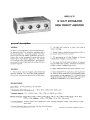
MODEL HF 12
12 WATT INTEGRATED
HIGH fIDELITY AMPLIfIER
general description
_
2. Two high level inputs for tv, tuner, and crystal or
ceramic ca rtridge.
GENERAL
The HF12 is a true high fidelity 12-watt integrated ampl ifier absolutely free of the "gimmi cks" sometimes used in
low-priced amplifiers. It provides complete "front end"
facilities and true high fidelity performance of such exce llence that we can recommend it unreservedly for any
medium-power high fidelity application. Two HF 12's
may be used for stereo tape reproduction, each amplifier
connecting directly to a tape head with no other electronic
equipment required.
3. Unused inputs a re shorted at every position of the input selector switch for zero cross-talk.
4. DC superimposed on all tube fi laments to el imina te
cathode-heater leakage as a source of hum.
5. Low-no ise dual triode used exclusively for separate
bass and treble tone controls. Extremely low distortion,
variable crossover, feedback-type circuit.
6 . Highly stable Wi lIiamson-type powerampllfier c ircuit .
FEATURES
7. Newly-designed "flat" construction, utilizing horizontal chassis to permit properlayout and component separation necessary for long component life. Extremely fl exible
design permits easy console installation with com pie t e
shielding and adaptability to any panel thickness.
1. Two low level inputs far magnetic phono (RIAA) and
tape head (NARTB). Low noise dual triode preamplifier
with accurate, low distortion equal izatlon for either Input.
SPECIFICATIONS
Output Power: 12 watts continuous, 25 watts peak.
* 1M
*
Distortion (60 & 6000 cps at 4: 1): 1.3% at 12 W; 0.55% at 6W; 0 .3% at 4W.
Frequency Response: 1 W : ±0.5db 12 cps - 75kc; 12W: ±0.5db 25 cps _ 20kc.
*Harmonic Distortion: 20cps: 2% at 4 .2W; 1/2% at 2.5W; 30cps : 2% at 11 W; 1/2% at 6.3W; 40cps : 1% at 12W;
1/2% at 9.3W; 2000 cps : 1/2% at 12W; 10kc : 1% at lOW; 1/2% at 6W.
* Transient Response: excellent square wave reproduction (4 usec risetime); negligible ringing, rapid settling on 10 kc .
square wave.
*
Transient Distortion (60 cps tone burst>: less than 1% at full power.
COPYRIGHT (C) 19 60 ElECnONIC IN sn UM EN T COMPANY, In e.
1
Inverse Feedback: 20 db
Stability Margin: 12db
Damping Factor: above 8, 20 cps - 15 kc.
Speaker Connections: 4, 8, and 16 ohms.
Sensitivity (input for 12W): mag. phono - 5mv; tape head - 2mv; tuner, auxiliary - 0.5 v .
Hum & Noise Level (below 12W): mag. phono - **60db; tape head - **50db; tuner, auxiliary - 75db .
Tone Control Range: at 10kc, :f:13db; at 50cps, ±16db .
Tubes: 3- ECC83/12AX7, 2- El84, 1- EZ81.
Size: 35/8" high, 12" wide, 81/4" deep.
Weight: 131bs.
* Meosured from high level Inputs with tone controls set at "flat" positions.
** Inc Iudes effect of compensation.
2
mechanical installation
_
a) HEAT DISSIPATION (VENTILATION): In common with
other electronic equipment, the HF-12 produces considerableheatin normal operation. Unless continuous and adequate air flow is obtained around the heat producing elements, these elements will over-heat and their useful life
will be greatly curtailed.
CONSOLE MOUNTING
a) Operations on console front panel preliminary to amplifier mounting: (1) Tape the panel template provided
to the face of the console so that the top of the mounting
surface line on the template is level with the top of the
amplifier mounting shelf. (2) Use an awl or a nail to
pierce the centers of the four 5/8" diameter holes for the
controls, the 3/8" hole for the vi ewing of the pilot lamp,
and the two sma II ho Ies for mounti ng the contro I pia te, to
transfer their locations to the console panel beneath. (3)
Remove the panel template. (4) Dri II the holes for the
ponel controls and the pilot vi ewing ho Ie (the two sma II
holes which have been marked are for wood screws).
It Is useful to understand the process of convection whereby heat is removed In judging the suitabilltyofa location.
Air heated by the heat-producing elements expands and
rises; cool air is drawn from beneath to take the place of
the heated air. In this manner, a stream of air Is set in
motion which continually removes heat from the amplifier. (In particular, we are mainly concerned with the
mcler heat-producing elements; the two EL84 output tubes
and the EZ81 rectifier tube.) If there Is any impediment
to or constriction of the air flow, the essential process of
heat removal wi II be adversely affected.
b) Amplifier mounting in console: (1) Pull off the control knobs . (2) Remove the control plate, which is attached to the bezel by two screws. (These may be discarded since they are unsuitable for attaching the control
plate to the console panel and two '4X3/8 wood screws
have been supplied for this purpose.) (3) Fasten the control plate to the console panel with the 2 '4 X 3/8 wood
screws . (4) If the rubber feet have been inserted in the
bottom plate, remove them. (They may be pried out with
a thin screwdriver. ) (5) Remove the four screws that fasten
the bezel to the side pieces and remove the bezel, which
is not used in console mounting. (6) Place the unit on the
mounting shelf and slide it as for forward as possible, so
that the controls penetrate the panel holes as for as possible. (7) Place a knob on each control, pressing each
knob toward the chassis firmly so that each control shaft
enters fully into its knob . (8) Draw the chassis bock evenly
and carefully unti I the back rims of all the knobs are equally
spaced from the control plate about 1/8". (9) Wi th a
sharp pencil, draw the outl ine of the side and rear bottom
edges on the chassis shelf. As the bottom plate falls short
of the full width by 3/16" on each side, draw new side
edge lines 3/16" inside the original side edge lines. (10)
Now remove the knobs and take the chassis off the shelf.
(11) Remove the6 screws which fasten the bottom plate to
the chassis. (12) Place the bottom plate exactly in the
outline drawn on the shelf and mark the position of the
center hole on the left side and the center hole on the
right side. (13) Remove the bottom plate and drill each
of the marked holes on the shelf to a diameter of 1/4".
(14) Refasten the bottom plate to the chassis, with the
four of the six 18 X 3/8 screws previously removed, using
the two holes at the rear and the two holes at the front of
the chassis. (15) Replace the chassis on the shelf, positioning it exactly in the outl ine previously drawn, and restore
the knobs. This time make sure that the indicator do t on
each knob agrees with the control position. (16) From the
bottom side of the shelf, insert a 18 XI" screw, with 01/2"
flat washer against the head, through both the left and
right side center holes. These screws engage the stamped
nut over each hole on the chassis flange and when tightened
secure the chassis to the shelf .
Adequate venti lotion will be provided if the amplifier is
installed in an open-bock console provided that the top
of the amplifier is spaced at least two Inches below any
shelf mounted above It . If the cabinet is enclosed at the
rear, provide several large holes or slots as low down and
as high up in the cabinet bock as possible. As an alternate, holes may be provided In the sides, bottom, or top
of the cabinet. The important thing to remember Is that
effective ventilation requires provision for cool air to enter at the bottom and hot air to leave at the top .
If the amplifier Is not installed in a console, it may be
situated on an open surface or on a shelf of a bookcase.
Four rubber feet arealso provided so that the ampliflerwil I
not mar the surface of furniture on which It is placed.
b) EASY ACCESS TO CONTROLS: Mount the amplifier
ata height which will permit easy manipulation of the controls. Tuner controls should be located nearby .
c) ACCESSABllITY TO PARTS: Tubes are the most frequently replaced Items In electronic equipment. If the
amplifier is Installed ina console, sufficient spoce should
bealloted to reach and remove any tube in the amplifier.
Furthermore, input and output terminals of the amplifier
should be accessible to permit easy interchanging of system components for comparison, and connection or disconnection of a portabl e tape recorder which is stored away when not In use. If antennas are strung around the
back of the console In which the amplifier is installed,
arrange them so they will not interfere with access to the
amplifier.
d) ACOUSTICAL ISOLATION: If amplifier and speaker
are Installed In the same cabinet (not recommended), provide sufficlent seporatlon to minimize mechanical speaker
vibration reaching the ampllfi er. The minimum seporatlon
Is about one foot.
3
electrical Installation
_
and low capacity snlelded cable (cable having as low
25mmfd capacitance per foot Is available) .
GENERAL
a) SPEAKER CONNECTIONS: To connect your speaker
to the amplifier properly, you must know Its rated Impedance . This may be read off tne speaker nameplate. Connect one speaker lead to the" G"termlnal on the rear apron
and tne other speaker lead to tne nearby terminal corresponding to the rated speaker Impedance (4, 8, or 160hms).
Plastic-covered lamp cord may be used for distonces up to
50 ft. wltn little power loss. For shorter distances, TV
ontenno lead can be used, particularly If It Is desired to
run the speaker lead under a rug.
01
If ftle tuner employed has a valume control to adlust ftle
output, set this control to give about tne same sound level
for any given setting of the amplifier VOlUM Econtrol 01
obtained from an average orchestra l recording played on
your phonograph. If you do this, there will not be any
extreme change in sound level when switching from phonograph to tuner or vi ce versa.
e) TAPE OUTPUT: A shielded cable (up to 30 ft. may be
used) with a shie lded "phone-type" p lug should be used
to connect from the TAPE OUTPUT lack to the Input of the
~pe recorder. Any input chosen by the SELECTOR Is fed
out to the tape recorder through this jack. Phono inputs
fed In at MAG. PHONO are of course equalized accordIng to tne RIAA characteristic and a ll the inputs are affected by the level and tone controls.
If It Is desired to use two similar or Identical full-range
speakers of the same rated Impedance (either 8 or 16 ohms
on ly) for better sound distribution, connect one speaker
lead of each pair to "G" and the two remaining leads to
the terminal with a number equal to half of one of the
speaker's rated impedance. (It may be necessary to "phase"
the two speakers by reversing both of the leads from one
of tne speakers.) This may not be done if each of the
speakers Is designed for reproduction of a different part
of the audio spectrum (woofer-tweeter combinations) In
which case a cross-ever network Is required which connects to the amplifier with only one pair of leads.
f) POWER CONNECTIONS: The 117VAC, 250W receptacle is "live" or "dead" depending on whether the
amplifier power switch is turned on or off . By plugging
Into It the line co rds of associated equipment (tuner, tape
recorder, etc.) it is possible to turn these components on
or off with the amplifier. Use a cube tap if It Is desired
to connect more than one device. Record changers and
tumtables should be plugged into a wall outlet as a protection to the mechanisms of these units.
b) MAG. PHONO INPUT: This Input is intended for use
with phonographs having magnetic cartridges. The shielded lead from your phonograph should be provided wltn a
shielded plug. The loading reslstonce presented to the
cartridge at the Input Is 47,000 ohms, which Is the most
generally suitable loading resistance for magnetic cart·
ridges.
HUM ADJUSTMENT
a) After checking the amplifier for proper operation, remove all input cables to the amplifier and makethe followIng control settings which hold throughout the process of
hum adjustment: SELECTOR at PHONO, LEVEL to 10 ,
TREBLE centrci at -5, BASS control at O. Next, procede
01 follows: With your ear held close to the speaker, insert
the amplifier power plug into the wall outlet and listen to
tne hum level. Now pull out the plug and reinsert it with
tne prongs reversed and Iisten again . Choose the prong
position which gives the least hum. Now connect the tuner
input connector to the amplifier input jack, andwlth tuner
set between stations and the tuner volume control set at
minimum, do the same with the power plug of the tuner,
using tne 117VAC convenience outlet on the amplifier if
desired . Finally connect the phono input connector to the
amplifler MAG. PHONO or AUX. Input (as required) and
find the lowest hum position for the power plug of the
phonograph In a wall outlet. Do this with the phonograph
off and the pickup arm at rest position.
c) TAPE HEAD INPUT: This Input Is Intended fer receivIng tne output signal directly from tne playback head of a
tape deck. NARTB tape head equalization for 7 1/2 and
15 I.p.s. tape speeds Is applied to signals fed In at this
Input. The load ing resistance presented to the tape head
Is 100 ,000 ohms.
d) HIGH lEVEL INPUTS: Two high level Input Jacks desIgnatedas Tuner and Auxiliary are provided for connection
of tuners, tv receivers, equalized and pre-ampllfled tape
recorder playback, and ordinary or RIAA equalizing crystal
or ceramic phono cartridges without adaptor. A shielded
cable with a shielded "phone-type" plug should be used
to connect each of these sources to the corresponding amplifier input Jack. Unless the source has a low-Impedance
output such as a cathode follower{wlth which up to 50 ft.
of cable can be used), use tneshortestpasslble connectton
4
operation
_
desired. The corresponding high level input will feed
through the ampl ifler. Adjustment of the level control on
each source is discussed in the" ELECTRICAL INSTALLATION" section under" High Level Inputs".
PRELIMINARY: Be sure all tubes arefirmly seated intheir
sockets and that the VI tube shield is making good contact
with its base. As initial adjustments, set these controls
as follows: VOLUME at zero, BASS at zero. Turn the amplifier on by turning the TREBLE control clockwise from
OFF and set It at zero Initially. Note that the VOLUME,
BASS, and TREBLE controls all affect the TAPE OUTPUT.
MAKING RECORDINGS: Tape recordings may be made
by connecting the recorder to the TApE OUTPUT jack . See
"Tape Output" under "ELECTRICAL INSTALLATION"
Please note that recordings cannot be made on tape decks
intended only for sterea or monaural tape playback . Recordings can only be made on tape machines having recording facilities including the necessary el ectronic equipment,
whlchmaybe either built-in or supplied seporately by the
tape deck manufacturer.
LISTENING TO PHONOGRAPH: Set the SELECTOR to
PHONO if you have a magnetic cartridge or AUXiliary If
you have a ceramic -or crystal cartridge. The RIAA equalization provided for magnetic phono cartridges Is now the
standard In the recording Industry and is also a very good
compromise for the most important of the older characteristics. The better ceramic cartridges are also self-equalizing
according to the RIAA chorocterlstlc . Use the separate
bass and treble tone controls to compensate for inexact
matching of the actual recording characteristic as well as
the over-all characteristics of your audio system (Including
room acoustics).
BASS CONTROL: The plus sign on the right side of the
dial indicates that clockwise rotation from the mid-point
(0) Increases (boosts) bass response; the minus sign on the
left side indicate that counter-clockwise rotation from the
mid-point decreases (cuts) bass response . There is no interaction with the TREBLE control. Start all adjustments
with this control set at the mid-point (0), wh ich Is called
the "flat" position since bass repsonse is ne ither cut nor
boosted at this setting .
LISTENING TO TAPE DECK (direct connection to tape
head): Set the SELECTOR to TAPE HEAD. NARTB tape
equalization for the 7 1/2 and 15 I. p. s. speeds is provided
by the preamplifier-equalizer at this position . This equalization Is the industry standard for pre-recorded sterea and
monaural tapes. The bass and treble tone controls can be
used to compensate for Inexact matching of the actual recording characteristic.
TREBLE CONTROL: The plus sign on the right side of the
dial indicates that clockwise rotation from the mid-point
(0) increases (boosts) treble response; the minus sign on
the left side indicates that counter-clockwise rotation from
the mid-point decreases (cuts) treble response . There is no
interaction with the BASS control. Start all adjustments
with this control set at the mid-point (0), which is called
the "flat" position since treble response is neither cut nor
boosted at this position.
LISTENING TO TUNER, TV, TAPE RECORDER HAVING
BUILT-IN PLAYBACK PREAMPLIFIER - EQUALIZER: Set
the SELECTOR to TUN or AUX depending on the Input
maintenance
_
TROUBLE SHOOTING & OPERATING NOTES
TROUBLE-SHOOTING PROCEDURES
Your amplifier should require little service except for normal tube replacement. We recommend no substitutions for
the tube types used in this amplifier except as stated. All
the tube types used are distributed nationally , but replacements can be obtained directly from EICO If desired.
Connect a phonograph and speaker to the amplifi er as described in "Electrical Connections" and set controls for
phono listening. Playa known high quality LP recording
on the phonograph . If there is no output to the speaker
or if the output Is low or audibly distorted, procede to the
checks for those symptoms. If there is excessive hum in
the output, disconnect the phono input cable from the
amplifier and short the phono input jack to chassis . If the
hum disappears, the trouble is not in the amplifier but in
the phonograph or in the connection to the ampl ifier .
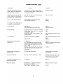
Tofacilitate servicing, remedial and trouble-shooting procedures have been provided in the TROUBLE-SHOOTING
CHART tho t follows . A VOLTAGE AND RESISTANCE
CHART is a lso provided as an aid In locating defective
components. DC operating voltages are given both at no
signal and signal developing 50 watts output, as wei I as
the corresponding I kc signal voltages.
The cause of phonograph hum may be a metal pick-up arm
not grounded to the cable shield (try a good single ground
5
cal'"C l n u
cr":]"-ClCIf"!II~II C .
TROUBLE-SHOOTING A TYPICAL TUBE STAGE
connection to the cable shield from turntable frame, pickup arm, and cartridge case), dired hum pick-up by the
magnetic cartridge from the record player motor (try using
a rubber mat on the turntable to Increase the separation of
the pick-up from the motor), or pick-up from a power transformer or other magnetic field in the vicinity (try moving
phonograph away from suspected source). Check also that
the phono input cable shielding Is grounded to the amplifier chassis at one point only through the skirt of the Input
connector where it plugs Into the amplifier. Finally, try
a good building ground such as a connection from a cold
water pipe terminated under speaker terminal II Gil on the
amplifi er. Do not connect such a ground wire to other
components In the system.
1. Check tube.
2. Check plate and cathode resistors.
3. Check coupling capacitors for leakage or short.
4. For output stage, check de resistance of transformer
windings.
5. Check grid leak resistor for open.
6. Check cathode by-pass capacitors for short.
7. If no or low B+ voltage on tube, check decoupling
path for open or defective R18, R31, R32, R33 and filter
capacitor C17 or C18.
8. If wiring and circuit components including the tube
check O . K. and B+ voltage is excessive, check the decoupling path for short or defective R18, R31, R32, R33.
Excessive hum on other inputs may be checked in a similar
manner. Disconnect the Input cable In question and short
the particular input jack to the chassis. If the hum disappears, the trouble is extemal to the amplifier. Note
that on all inputs, the braid of the Input cable should connect to the amplifier only through the skirt of the Input
connector. The cause and remedies for the following symptoms are then based on the assumption that checks made in
the manner described above have eliminated the possibll ity
of the trouble being external to the amplifier.
Suspected trouble in the equalization, tone, and volume
controls and networks should lead to specific resistance
and capacitance checks to localize the trouble. In general, if the user suspects poor frequency response, defective equal ization, or defective operation of the tone controls, the amplifier should be tested thoroughly with audio
generator, vtvm, and scope.
SERVICE
If the trouble is no output or low output, checkAC signal
voltages and DC operating voltages starting at the input
and working step-by-step toward the output. Set the
VOLUME control to maximum (10), and the BASS and
TREBLE controls to their mid-points (0). Use a 1000 eye Ie
sinewave signal, such as supplied by the EICO 377 Sine &
Square Wave Audio Generator. In addition, use a precision 100: I attenuator to permit obtaining a level of
0.01 volt fedintoMAG. PHONOfrom an audio generator
output of 1 .0 vol t, which can easily be measured on the
lowest ACvolts range of yourVTYM(also improves signal
to hum from generator). Use a high input Impedance VTYM
for allAC signal voltage measurements (such as the EICO
232,249,221, or 214) and aVTYM or20,000n/voltVOM
for DC voltage measurements.
If trouble develops in your instrument which you ccn not
remedy yourself, write to our service department listing
all possible indications that might be helpful. Note number appeari ng in red under the word" ManuaP' on the front
cover. If there is no number, state this. If desired, you
may return the instrument to our factory where it wi II be
placed in operating condition for $7.50 plus the cost of
parts replaced due to their being damaged in the course
of construction. NOTE: Before returning this unit, be
sure all parts are securely mounted. Attach a tag to the
instrument, giving your home address and the trouble with
theunit . Pack very carefully in a rugged container, using
sufficient packing material (cotton, shredded newspaper,
or excelsior), to make the lonitcompletely immovable
within the container. The original shipping carton is satisfactory, providing the original inserts are usedor sufficient packing material is inserted to keep the instrument
immovable. Shipby prepaid Railway Express, if possible,
to Electronic Instrument Co., Inc., 33-00 Northern Blvd. ,
Long Island City 1, N. Y. Return shipment will be made
by express collect. Note that a carrier cannot be held
liable for damages in transit if packing IN HIS OPIN ION,
is insufficient.
If the troubl e is an excessively distorted output, try tube
replacement, signal tracing, or procede directly to vol tage
and resistance measurements.
When the defective stage is localized, precede to a resistance and vol tage check of the stage, using the data In the
VOLTAGEand RESISTANCEchart. Disconnect the ampll-fler from the power line and discharge capacitors prior to
making any resistance check and prior to removing either
or both of the EL84 output tubes V4 and V5. Do not turn
the amplifier on with either of the output tubes removed.
6
TROUBLE-SHOOTING CHART
SYMPTOM
CAUS E
REM ED Y
Amplifier causes power line fuse
to blow. Power Iine fuse blows again with V6 out of socket.
Line cord, J6, primary or high voltage
secondary windings of T2 shorted internally
or externally (wiring).
Replace or repair.
Amplifier causes power line fuse
to blow. Power line fuse does not
blow again with V6 out of socket.
V6, C17, V4, V5, or T1 primary shorted
internally or externally.
Replace or repair.
Any or all tube filaments not lit.
Open lead from 6.3V winding of T2.
6.3V winding of T2 open.
Repair
Replace
a) No voltage
Defective V6
C17 shorted internally or externally.
Replace
Replace or repair.
b) High voltage.
Connection from C17 to pin 9 of V6 broken.
Connection to center tap of h. v , secondary
winding of T2 open.
Output tubes V4 & V5 over-biased or not
drawing current.
Repair
Repair
DC voltage at V6 cathode (pin 9)
is incorrect as specified below.
c) Low voltage.
Excessive current drain in amplifier.
Defective V6
See trouble-shooting typical tube
stage.
See trouble-shooting typical tube
stage.
Replace
Vl defective
Fil. leads dressed too close to grid lead.
Tube shield not making electrical contact
to base or base not making electrical contact to chassis.
Shielding and grounding of wiring to input
jacks not exoctly as instructed and shown
in drawings.
Replace
Dress fi I. leads away from grid lead.
Check and correct
Excessive noise on mag.phono
and tape head
V1 socket and contacts dirty.
Clean throughly with carbon
tetrachloride.
Sustained oscillations.
poor dress of output transformer T1 leads
Dress all input leads and T1 leads
away. from each other. Keep T1
leads away from input lacks.
Sustained microphonics on mag.
phono 'and tape head.
Vl defective.
Replace
Hum on all inputs
V2 defective, not properly shielded, or
dirty sockets and contacts.
Dress of power transformer 12 leads.
Replace, correct, or clean.
Excessive hum on mag. phono
or tope head.
7
Correct
Correct
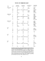
VOLTAGE AND RUtSTANCE CHART
TUBE
PIN'
DC VOLTS
NO SIGNAL
DC VOLTS
12W OUT
AC VOLTS (1 kc)
12W OUT
RESISTANCE
UNIT OFF
ECC83/12AX7
VI
1
2
3
4&5
6
7
8
9
108
108
0.52
0
0.028
0
1.2
1.2
0
filament (12 - 14DC; 6.3VAC to pin 9)
68
68
0.028
0
0.005
0
0.009
0.6
0.6
filament
300KO
lMO
4.7KO
165-1900
300KO
480KO
2.2KO
165-1900
ECC83/12AX7
V2
1
2
3
4,5
6
7
8
9
2
185
185
0
0.5
0
1.4
0.265
1.4
filament (12-14VDC; 6.3VAC to pin 9)
1.38
180
180
0.26
0
0
0.135
1.6
1.6
filament
75KQ
500KO
1.2KO
165-1900
130KO
400KO
3.3KO
165 - 1900
ECC83/12AX7
V3
1
2
3
4&5
6
7
8
9
190
91
190
7.7
90
8
7.7
93
92
filament (12 - 14VDC; 6.3VAC to pin 9)
91
8
90
0
1.37
0
1.25
0.8
0.85
filament
120KO
480Kn
IOCKO
165-1900
480KQ
210KO
1.8KO
165-1900
ELM
V4
1
2
3
4&5
6
7
8
9
7.7
0
0
12
0.05
14.2
filament (12 - 14VDC; 6.3VAC between)
340KO
165-1900
165-1900
ELM
V5
EZ81
V6
1
2
3
4&5
6
7
8
9
12
3
4& 5
6
7
8
9
330
324
176
1600
336
330
3.9
0
7.7
0
0
.05
12
14.2
filament (12 - 14VDC; 6.3VAC between)
340KO
165-1900
165-1900
330
324
176
2000
336
330
3.9
0
280
336
330
filament (12 - 14VDC; 6.3VAC between)
280
336
330
8
950
160KO
165-1900
950
160KO
Section
Selector
AUX
TUNER
PHONO
TAPE HEAD
1 - 11,
2 - 11,
3-10-11,
3-4-11,
3- 4
4-5
11 - 12,
1-11-12,
A
5-6
6-7
Switch
1 - 2 - 11 - 12,
1 - 2 - 12,
B
2 - 3 - 5
8-9
3 - 5,
5 - 8,
8-9
9 - 11
Entries are numbers of those switch contacts which are
connected together by the rotors at the particular position.
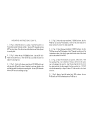
11 7VAC
HUM
~[]
I I
M OO "
".,.
I"!IGH F ' OE:.LlTV
1'2 W A TT AMF' LI f-l i:.R
ADJUST
2 50W
o
I 'mm°(i)"Ci)' I
OUTPUT
16
S
4
G
AUX
TUNER
MAG.
TAPE
00 00
PHON O
HEAD
TOP vlrw
o o
V -5
V -4
M O Oi:. L "''''2
"' .GH F IDE L" "
o
V-1
ECC S3!12AX7
E L S .4
o
0
ELS4
V -3
V-2
ECCS3!12A X7
o
V -6
POW E R CO NS.UMP TIO N
l!Ll!CTRON IC ',," S T
co
"', C
E ZS1
ECCB3 !12AX7
nONT
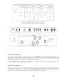
TRANSFORMER TEMPERATURE
The temperature of the transformers used in the HF-12 run at less than 1950 despite the fact that the safety limitis at a much
higher 221 oF. Although 19SOF is cool for a transformer, it is very hot to the touch. Transformers which seem too hot when
touched with the hand, are usually good and are actually not overheating.
Output transformers usual! y run cooler than power transformers. Some output transformers may appear hotter than others due
to being located near hot components such as output and power tubes and power transformers.
OUTPUT TRANSFORMER LOAD
The output transformer and the output tubes of any amplifier are subjected to severe stress when the amplifier is operated at
a high signal level without a load. To protect these components against possible damage, always have either a speaker or
resistive load connected to the output terminals of the amplifier while it is being operated.
9
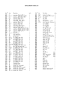
REPLACEMENT PARTS LIST
Stock'
Sym.
20050
22517
22549
22514
23020
20044
20039
22529
22539
22533
23007
20043
23016
Cl
C2,12,13
C3
C4,6
C5
C7
C8
C9
Cl0,11
C14
C15
C16
C17
C18
C19
C20
C21
24005
22507
22523
23014
92000
50011
50014
50016
29751
10410
10431
11526
10423
10430
10407
11504
10400
18038
18033
18034
10426
10427
10420
10853
11543
11527
10412
14600
11538
19009
10422
10520
10425
10419
60049
32005
30019
54017
54500
54002
54004
54015
54000
Description
cap., paper, .25 mfd - 200 V"
cap., dlsc.; .025mfd (25K or 25,0(0)
cap., dlsc., .003mfd (3K or 30(0)
cop., disc., 850mmf, 10%
ccp., elec., 25 mfd - 6 V ••
cap., molded, .25 mfd - 400 V co
cop., molded, .1 mfd - 400 V ."
cap., disc., 150mmf, 10%
cop., dlsc., 200mmf, 10%
ccp., disc., 47mmf, 10%
cap., elec., 50mfd - 25V ' •
cap., molded, .03 mfd - 600 V • 1
cap., e lec., 30mfd - 400V •
ccp,; elec ., 20-40-4Omfd-400-350-350V
cop., disc., .0022mfd, 10% (2.2K or 22(0)
cop.; disc., .0068mfd, 10% (6.8K or 6800)
cap ., e lec ., 10 mfd - 6 V • ,
pilot light
11
JI-2,3-4
jack, dual phono
J5
lack, single phono
J6
outlet, convenience
printed circuit
PCl
Rl,15
res., 100Ko, I/,ZW, *10%
R2,19,36
res., 470m,I/XH, *10%
R3,4
res., 200KO,1/2W, * 5%
R5
res., 2.2KO, 1/XH, *10%
R6
res" 4.7KO, 1/XH, *10%
R7,8
res., lMQ, 1/XH, *10%
R9
res., 9OKo, 1/2W, * 5%
Rl0,21,26,27res.,10KQ, 1/2W, *10%
Rll
pot., 300m, audio taper (volume)
R12
pot.; lMQ, linear taper (bass)
R13, S2
pot., 500m, linear taper, CT (treble)
R14,32
res., 33m, 1/XH, :tJO%
R16
res., 1.2KO,1/XH, *10%
R17
res., 3.3KO, 1/2W, %10%
iw, %10%
R18
res., 10Ko,
R20
res., 1.8m, 1/XH, % 5%
R22,23
res., 100KO,1/XH, % 5%
R24,25
res., 330m,1/XH, %10%
R28
res., 1650,
5W,* 5%
R29
res" 22KO, 1/2W, * 5%
R30
por., 1000, (hum adjust)
R31
res ., 68Ko, 1/2W, *10%
R33
res., 68Ko, 1/XH, * 5%
R34
res., 56Ko, 1/XH, *10%
R35
res., 270Ko, 1/2W, *10"~
sw itch, selector
SI
transformer, output
T1
T2
transformer, power
TBI
terminal strip, 1 post upright
TB2
terminal board, 4 post
TB5
terminal strip, 1 post right wlgnd
TB4,9
terminal strip, 2 post wlgnd
TB6
terminal strip, 3 post, 2 left w/gnd
TB7,11, 12 terminal strip, 1 post left
Arn't.
Stock'
Sym.
Description
1
3
1
2
1
1
1
1
2
1
1
1
1
1
1
1
1
1
2
1
1
1
2
3
2
1
1
2
1
4
1
1
1
2
1
1
1
1
2
2
1
1
1
1
1
1
1
1
1
1
1
1
1
2
1
3
54003
54013
90034
90039
90038
97712
97027
97025
40000
40001
40007
40008
TB8,3
TB10
Vl,2,3
V4,5
V6
XII
XVI
XV2-6
terminal strip, 2 post
2
terminal strip, 1 post leftw/gnd 1
tube, 12AX7
3
tube, EL84
2
tube, EZ81
1
pilot assembly
1
socket, 9 pin min. top mount
1
socket, 9 pin min. bottom mount 5
25
nut, hex, '6-32
nut, hex, '3/8
5
16
nut, hex, '4-40
nut, hex, '8-32
12
nut, tin. '8-32
6
nut, an~le tin dual'8
2
screw, 6-32 x 1/4
25
screw, '8-32 x 3/8
6
screw, *4-40 x 1/4
12
screw, '4-40 x 1/4 brass
2
screw, '4 wood
2
screw, *8-32 x 1
2
screw, 116 P. K. brown finish
4
screw, 118-32 x 3/8 brown finish 4
screw, '8 P. K.
4
washer, lock, '3/8
5
washer, flat, '3/8
1
washer, lock, 116
22
washer, lock, 114
14
washer, lock, '8
12
washer, flat, '8
2
lug, '6
2
lug, '8
1
grommet, 3/8
1
feet, rubber
4
insulator for 50011
2
plug, phono
5
knobs
4
Iine cord
1
wire, hook-up
length
spoghetti
length
coble, single conductor
length
cable, 4 conductor
length
wire, bare 1122
length
control plate
1
chassis
1
bezel
1
bottom p Iate
1
bracket, left
1
bracket, right
1
perforated screen
1
label, rear apron
1
label, tube layout
1
tube shield
1
jewel, red
1
manual of instruction (wired)
1
manual of instruction (kit)
1
40026
40027
41000
41003
41016
41026
41027
41028
41045
41046
41047
42000
42001
42002
42007
42008
42032
43000
43004
46000
46006
50012
51006
53007
57000
58004
58300
58408
58410
58501
80049
81084
81091
81092
81103
81104
81105
89204
89205
97300
97710
66052
66304
Am't.
c
J5
(;)TAPE
~29
(14
8
C20
":"
T1
--
-
__
M
T2
,
~
AUX.
Jl
TUNER
J2
le I I
I
PHONOJ3
TAPE J4
~
Description
cop.,
CI
C2
cop.,
C3
cop.,
cop.,
C4
cap.,
C5
C6
cop.,
C7
cap.,
C8
cop.,
C9
cap.,
Cl0 cap.,
Cll cop"
C12 cap.,
it!;!&
• 25 mfd
• 025 mfd
3OOOmmf, 10%
85Ommf,lO%
25mfd-6V
85Ommf, 10%
.25mfd-400V
.1 mfd -400V
150mmf,10'll.
200mmf, 10%
200 mmf, 10%
.025mfd
~
Description
~
Description
~
C13
C14
CIS
C16
C17
CI8
C19
C20
C21
)1
J2
J3
cop.,
cop .,
cop.,
cop.,
cop.,
cap.,
cop.,
cop.,
cop.,
)4
)5
)6
Ieek,
11
147
l001CQ. I/ZW, ±10%
470KQ, I/ZW,±IO%
2OO1CQ. I/ZW, ± 5%
2OO1CQ. 1/ZW, ± 5%
2.21CQ. 1/ZW, ±10'll.
4. 71CQ. I/ZW, ±1O'll.
lMCl, 1/ZW,±IO'll.
res" lMQ, I/ZW,±IO%
R9
RIO
Rll
R12
R13
RI4
RI5
R16
RI7
R18
R19
R20
. 025 mfd
47mmf,10%
50mfd - 25V
. 03 mfd - 600 V
30mfd -400V
20-40-40 mfd - 400-350-350
2200mmf,10%
6800 mmf, 10%
10mfd·6V
[cek, aux, inp..It
lock, luner Input
jock, phono input
Rl
R2
R3
R4
R5
R6
R7
R8
tope input
jock, tope output
convenience outlet
b.Jlb,
res .,
rei.,
res.,
rei.,
res.,
rei.,
res.,
Descdption
rel.,90Kn.
v/z«.« 5'l(,
rei ., IOICQ. 1/ZW,*IO%
pot., 5OO1CQ. oudio(volume)
pet., lMn,. linea' (boss)
pot., 5OO1CQ. lineor(treble)
res., 331CQ. I/ZW,±IO%
rei., l00KQ, I/ZW, ±10'll.
res.,1.21CQ.I/ZW,±10'll.
res., 3.31CQ. 1/2W,±10%
lW,±lO%
res., IOICQ.
res., 470KCl, I/ZW, ±10%
res., 1. 8KCl, I/ZW, ± 5'l(,
~
Description
~
Description
121
rei .,
res.,
res.,
rei.,
res.,
res.,
rei .,
rei .,
res.,
pot .,
res .,
re•• ,
R33
R34
R35
R36
51
52
VI
re•• , 681CQ. 1/ZW,'" 5'l(,
rei., 561CQ. I/ZW,±IO%
res., 2701CQ. I/ZW, ",10%
res., 4701CQ. !/2W, ",10%
switch, seleetee
swlteh, on-off, port 01 R13
lube, 12AX7
lube, 12AX7
lube, 12AX7
tube, ELM
lube, ELM
lube, EZ81
R22
R23
124
R25
R26
R27
R28
R29
R30
R31
R32
101CQ. I/ZW,±IO%
1001CQ. I/ZW, * 5%
l001CQ. I/zw, * 5%
3301CQ. i/r«; ±I 0%
3301CQ. 1/ZW, *10%
IOKQ, I/ZW,*lO%
10KQ, 1/ZW,±lO%
165Cl,
SW,± S'll.
221<0, 1/2W,± S'll.
lOOCl, (hum odJu.t)
681CQ. !/ZW,±IO'll.
331CQ. 1/ZW,±IO'lE.
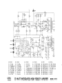
12 WATT INTEGRATED HIGH fIDELITY AMPLIfIER
V2
V3
V4
VS
V6
MODEL HF 12
•
GENERAL INSTRUCTIONS
The section of the manual beginning with this page is the CONSTRUCTION
section. All pages in this section have page numbers followed by "C" (lC,
2C, etc.). The INSTRUCTION section resumes on the pages following the
CONSTRUCTION section. Note thot the CONSTRUCTION section is located
centrally in the book and may be removed without desrupting the INSTRUCTION section that both precedes it ond follows it.
n
dered with the tip of 0 pair of longnose pliers . The pliers will conduct the
heot away and prevent the component from being unduly overheated. If for
any reason it Is necessary to resolder a joint, be sure to use new solder.
It should also be noted that the leads on resistors, capacitors, and transformers
are often longer than required. These leads should be trimmed to the proper
length when necessary . Do not cut any lead until you have determined the
required length when the lead is routed as shown in the diagrams.
Care taken in the construction of this instrument wi ll reward the constructor
with many years of satisfactory service and greater confidence in his instrument .
We urge you to not rush the construction, but to take all the time necessary
for proper assembly and wiring .
BASIC TOOLS REQUIRED : These basic tools are required for the construction
of the amplifier.
Furthermore, we urge strongly that you follow the wire and parts layout shown
in the pictorial diagrams as closely as possible. Very often wires are placed
as shown for a good reason, and certainly the appearance of the completed
Instrument will be improved and the difficulty of finding a wiring error wi II be
reduced by the following the wire and ports layout shown.
1.
2.
3.
4.
5.
6.
7.
UNPACKING THE KIT: Unpack the kit carefully and check each part against
the parts Iist Inc Iuding those parts that are mounted to the chassis. If you have
trouble identifying any parts refer to the pictorial diagrams or the color code
chart.
You will find that the value of a component will vary within the allowable
circuit tolerance. For example, the 4.7KO, ±10%resistor may measure anywhere between 4.2KO and 5.2KO. Tolerances on paper capacitors are substantially greater, and the tolerance for electrolytics is usually +100% and
-50%.
CONSTRUCTION HINTS: USE THE BEST GRADE OF ROSIN CORE SOLDER
ONLY, preferably one containing the new activated fluxes such as Kester
"Resin-Five", Ersin "Multicore" or similar types. UNDER NO CIRCUMSTANCES USE ACID CORE SOLDER OR ACID FLUX since acid flux can cause serious corrosion. Before soldering make a certain of a good mechanical connection. Use a clean, freshly tinned soldering iron, no smaller than 100 watts,
and place the solder on the joint (not on the iron)so that the solder Is melted
by the heat from the joint itself. Do not remove the soldering Iron until the
solder flows and check to see that the resul ting joint is smooth and shiny when
the solder has cooled. There are two extremes to be avoided; too little heat
and too much heat. If too little heat Is supplied, the joint will appear pitted
and grey, Indicating a rosin joint which is unsatisfactory. On the other hand,
If too much heat is appl ied to a joint, the parts connected to It may either
change value, loose their protective coating, or break down . If you are soldering close to a part, hold the lead between the part and the joi nt being sol-
Screwdriver - 3/16" to 1/4" blade
Screwdriver - 1/8" blade
Longnose pi iers - 5 or 6"
Diagonal cutters
Soldering iron (100 watts), or soldergun, or pencil iron (35 watts)
Gas pliers
High quality rosin or equivalent synthetic flux core solder. Do..!!2! use
acid or paste flux under any circumstances.
A set of spintites and a wire stripper are also very useful supplementary tools.
PARTS IDENTIFICATION: Please note that very many of the parts for which
color coding is given maynotbe color coded, but have their values and ratings
printed. The letter K is a multiplier(X1000) and on resistors or capacitors indicates that the printed numerical value must be multiplied by one thousand
to obtain the value in ohms or micro-micro farads respectively. Note also that
one microfarad (mf) is equal to one million; micro-microfarads (mmf). To aid
in rapid identificotion, keep in mind that 5%, 10%, and 20% resistors are
color coded whereas 1% resistor have their values printed; also that molded
tubular capacitors mayor may not be color coded, whereas disc capacitors and
electrolytics will always have their values printed. Please note the following
relationships between the units used to express resistance or capacity.
1,000,000 ohms (0) = 1000 kilohms (KO) = I megohm (MO)
1,000,000 micro-micro farads (mmf) = 1 micro farads (mf)
CONSTRUCTION PROCEDURE: The complete step-by-step mounting and wiring procedure follows. Tokeep thedrawingsuncrowded , unnecessary repetition
of mounting or wiring details may be omitted . Note: The abbreviation (!=)
means connect but do not solder (until other leads have been connected). The
abbreviation (S) means connect and solder.
Bend the ground lug tabs on the sockets toward the chassis to prevent accidental shorting to the socket pins.
e17
__
___ r'Y
nAr
l
/'
I
/
I
II
J
I
'\
---+- _ r
I
J
r."\. I
_
_______
XV4
TB6
TB11~
~
n
---TB3
XV6/
TB9
TB5
TB2
Xl1
TB1
XV5
J5
ii'C::~;-_
,
......
J"
J6 »>
R30
TB10
XV3~
XV2 ------
~~
r
=--..
~,-"
_
.,
~
.
'
J3-4
J 1- 2
-TB4
~
TB7 - - - - - - - -
If'J
XV1
:
---------./ TB 8
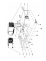
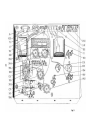
Fig. 1
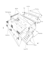
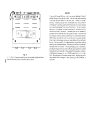
MOUNTING INSTRUCTIONS
NOTE; The chassis in Fig. 1 appears in expladed view. The angles on which
the tube sockets are mounted are actua Ily part of the chassis, but has been
moved up, out of the chassis, to make component mountings more obvious.
Refer to Fig. 3 for proper orientation of all components.
1. (J) Fig. 1. Mount the 9 pin miniature tube socket with shield base XVI
as shown. Use two #4-40 screws, two'4 lockwashers and two'4-40 hex nuts.
2. ('4 Fig. 1. Mount the 9 pin. miniature tube socket XV6 as shown. Use
two '4-40 screws, two #4 lockwashers and two '4-40 hex nuts.
3. (~ Fig. 1. Similar to the above, mount the 9 pin miniature tube sockets
XV2,XV3,XV4 and XV5 as shown. Use two '4-40screws, two '4 lockwashers
and two '4-40 hex nuts for each socket.
~
n
9. ( ) Fig. 1. Mount Cl'3 post, 2 left with ground terminal strip, T86, as
shown. Use one '6-32 screw, one '6 lockwasher and one '6-32 hex nut.
10. ( ) Fig. 1. Using the same hole , mount a 1 post left.terminal strip, TB7,
from the top and 30mfd electrolytic capacitor'"ICl7, as shown. Observe the
polarity on the capacitor. Use one '6-32 screw, one'6 lockwasher and one
'6-32 hex nut.
11. ( ) Fi~. 1. Mount the pilot light socket, XII, as shown. Use one'6-32
screw, one 6 lockwesher and one '6-32 hex nut.
12. ( ) Fig. 1. Mount a 1 post left with a ground terminal strip, TB10, as
shown. Use one '6-32 screw, one'6 lockwasher and one '6-32 hex nut.
13. ( ) Fig. 1. Mount input jack board, JI-2 as shown. Use a bakelite
insulator between the board and the chassis. Use four '6-32 screws, four '6-32
lockwashers and four '6-32 hex nuts.
4. ("~ Fig. 1. Mount the 4 screw terminal board, TB2 from the outside of the
chassis as shown. Use two *6-32 screws and two *6-32 hex nuts. Under one
'6-32 hex nut, mount a *6 ground lug. Under the other #6-32 hex nut, add a
1 post upright terminal strip, TB I, and a *6 lockwasher.
.
14. ( ) Fig. 1. Mount the input Jack board, J3-4 as above. Use bakelite
Insulator as above. Use four '6-32 screws, four'610ckwashers and four'6-32
hex nuts.
5. (tYFig. 1. Mount a 2 post terminal strip, TB3, as shown. Use one'6-32
screw, one '6 lockwasher and one '6-32 hex nut.
15. ( ) Fig. 1. Mount tape output Jack, J5, as shown. Use two'6-32 screws,
two '6 lockwashers and two '6-32 hex nuts.
6. (01g. 1. Using the same mounting hole, mount a two post with ground
terminal strip, TB9, from the bottom and a two post terminal strip, TB8,'from
the top. Use one #6-32 screw, one '6-32 lockwasher and one '6-36 hex
nut.
16. ( ) Fig. 1. Mount the hum adjustment pot, R30 as shown. Use one)/8
flatwasher, one 3/8 Iqckwasher and one 3/8 hex nut. Bend upper and lower
lugs so that they neither protrude over bottom of chassis or touch the chassis
proper.
7. (...("Fig. 1. Mount a 2 post with ground terminal strip, T84, as shown.
Use one '6-32 screw, one '6-32 lockwasher and one '6-32 hex nut.
17. ( ) Fig. 1. Mounttheconvenienceoutlet, J6 asshown. Use two '6-32
screws, two '6 lockwashers and two '6-32 hex nuts.
(0
Fig. 1. Mount a 1 post right with ground terminal strip, TB5, as
8.
shown. Use one '6-32 screw, one '6 lockwasher and one '6-32 hex nut.
18. ( ) Fig. 1. Push the grommet through the remaining 3/8 hole in the rear
of the chassis.
19. ( ) Fig. 1. Mount'6 ground lug "I". Use a '6-32 screw and a '6-32
hex nut. See Fig. 5.
20. ( ) Fig. 1. Mount a 1 post left terminal strip, TB 11, as shown. Use one
#6-32 screw, one '6-32 lockwasher and one '6-32 hex nut.
I-
.
N
....~
00
N
I-
U
4C
MOUNTING INSTRUCTIONS CONT'D.
1. ( ) Fig. 2. Mount the switch, S1, as shown. Note that the switch is In
the maximum counter-clockwise position. Use one 3/S" lockwasher and one
3/8" hex nutas shown. Note that tab on switch slides Into small hole adjacent
to mounting hole.
4 . ( ) Fig. 2. Mount the output transformer, T1 (32005) as shown. Use four
'S-32 hex nuh and four IS lockwashers . Note that the yellow lead and the
brown lead face the rear of the chassis toward T82.
Use one 3/S" lock-
5. () Fig. 2. Mount the power transformer, T2 (30019) as shown. Use four
'S-32 hex nuts and fourlSlockwashers. Add a IS ground lug under one of the
lockwashers as shown. Note thot the green leads face the center of the chassis
and the tube sockets XV4 and XV5.
3. ( ) Fig. 2. Similar to the above, mount the pat R12 (lS033) and the pot
with the switch, R13 and S2 as shown. Note that in each case, the tab on the
potslldes into small hole adjacent to mounting hole. Use one 3/S" lockwasher
and one 3/8" hex nut In mounting each pot.
6: ( , Fig. 2. Mount the electrolytic can capacitor, C1S as shown. Note
the mounting in Fig. 3 as to direction of triangle, semi-circle and square,
next to the prongs on the capacitor. Insert the mounting tabs into the slots In
the chassis and twist the tabs somewhat less than a quarter tum. DO NOT
twist the tabs excessively or they wi II shear off. Solder one tab to the chassis
at Its slot.
2. ( ) Fig. 2. Mount the pot, R11 (18038) as shown.
~ washer and one 3/S" hex nut . Note that the tab on pot slides into small hole
adjacent to mounting hole.
7. ( ) Fig. 2. Mount a 1 post left terminal strip, TB12, as shown. Use one
'6-32 screw, one *6-32 lockwasher and one '6-32 hex nut .
J6
R30
J3-J4
T2
J1-J2
J5
TB2
TBl
Tl
R28
~
TB3
XV5
XV4
TB6
XV6
~
~
~ ~~~ 7~
-;;;;-
~
C15
\
=teXV1
C18
~~TB4
~~
TB9
XV2
TB5
XV3
~
elf>
~
-.a>
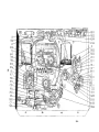
Fig.3
WIRING
INSTRUCTIONS
1. ( ) Fig. 3. Cut a 6" length of black wire and 6" length of brown wire .
Connect one end of the brown wire to XVl-9 (5) and one end of the black wire
to XVl-4 (5) through XVI-5 (5). Twist the two wires and run along the chassis
as shown. Connect the other end of the black wire toXV4-4 (C) and the other
end of the brown wire to XV4-5 (C).
2. ( ) Fig. 3 . Following the above pracedure, cut a 4" length of black wire
and a 4" length of brown wire. Connectane end of the black wire to XV4-4 (5)
and one end of the brown wire to XV4-5 (5). Twist the two wires and run along the chossls as shown. Connect the black wire to XV5-4 (C) and the brawn
lead to XV5-S (C) .
3. ( ) Fig. 3. Following the above procedure, cut a 4" length of black wire
and a 4" length of brown wire. Connect one end of the black wire to XV5-4(5)
and one end of the brown wire toXV5-5($). Twist the two wires and run along
the chassis as shown. Connect the black wire to XV3-5 (C) through XV3-4 (C)
and the brown wire to XV3-9 (C).
~
4. ( ) Fig. 3 . Following the above pracedure, cut a 3" length of black wire
anda 3"'ength af brawn wire. Cannect ane end oftheblackwire toXV3-5(5)
and one end of the brown wire toXV3-9(C). Twist the two wires and run along
the chassis as shawn. Cannect the black wire to XV2-4 ($) through XV2-S (5)
and the brown wire to XV2-9 (5).
S. ( ) Fig. 3. Following the above procedure, cut a 4" length of black wire
anda 4" length of brown wire. Connect one end of the black wire toXV3-4 (5)
and one end of the brown wire toXV3-9(5). Twist the two wires and run along
the chassis as shown. Connect theblack wire toXV6-S(C) and the brown wire
to XV6-4 (C).
6. ( ) Fig. 3. Following the above procedure, cut a 6" length of black wire
and a 6" length of brown wire. Connect one end ofthe black wire to XV6-5 (C)
and one end of the brown wire toXV6-4 (C) . Twist the two wires and run along
the chassis as shown. Connect the black wire to XIl-1 (5) and the brown wire
to XI1-2 (5) .
9 . ( ) Fig . 3 . Connect a 6" piece of yellow wirefromXV4-3 (C)toR30-2 (5).
10. ( ) Fig. 3. Connect a 3" pieceofyellow wire from XV4-3 (5)toXVS-3 (C).
11. ( ) Fig. 3. Cut both leads of the 16SQ, 5W resistor, R28, to 1" . Put
3/4" of spaghetti on one lead and leave the other lead bare. Connect the lead
wi th the spaghetti to XVS-3 (C) and the other lead to ground lug" A" (5) on XV4.
12. ( ) Fig. 3. Cut the lead on the positive end (+) of the SOmfd, 2S volt
electrolytic capacitor, CIS, to I 1/2" and the lead on the negative (-) to I 1/4".
Put I 1/4" spaghetti on the lead of the positive end and connect toXVS-3 (5).
Connect the negative lead to ground lug" B" (5) on XV6.
13. ( ) Fig. 3. Cut the lead on the positive (+) end of the 30mfd capacitor,
C17, to 2 1/2" and the tead on the negative (-) end to 3/4". Put 2 1/4" spaghetti on the positive lead and connect to XV6-9 (C). Connect the lead on
the negative end to TB 10-2 (C).
14. ( ) Fig. 3. Connect a 1" piece of bare wire fromXV6-9(5)toXV6-3 (C).
15. ( ) Fig. 3. Twist the red leads from the power transformer, T2. Run the
leads along the chassis as shown. Connect one red leadXV6-1 (5)and the other
red lead to XV6-7 (5).
16. ( ) Fig. 3. Twist the red-yellow and the white leads from the power transformer T2 . Connect ta ground lug "0" (5).
17. ( ) Fig. 3. Connect one black lead from the power transformer, T2, to
J6-1 (C) and the other black lead to J6-2 (C).
18.
( ) Fig. 3. Connect an 8 1/2" black wire from TBI (C) to XV3-8 (C).
19. ( ) Fig . 3. Connect the following leads from the output transformer TI,
to the output terminal board TB2:
Green lead to TB2-3(5)
Yellow lead to TB2-4(C)
Brown lead to TB2-2(5)
Black lead to TB2-I(C).
7. ( ) Fig. 3 . Following the above procedure, cut a 6" length of black wire
and a 6" length of brown wire. Connect one endof theblack wire toXV6-5(5)
and one end of the brown wire to XV6-4 (5). Twist the two wires and run along
the chassis as shown. Connect the black wire to R30-1 (C) and the brown wire
to R30-3 (C).
21. ( ) Fig. 3. Connect a 3 1/2" red lead from XVS-9(S) to XV4-9(C).
8. ( ) Fig. 3 . Twist the two green leads from the power transformer, T2, and
run along the chassis as shown. Connect one green lead to R30-3 (5) and the
other green lead to R30-1 (5) . '
22. ( ) Fig. 3. Connect a 1" piece of bare wire from TB2-1 (5) to ground
"E" (5).
23. ( ) Fig. 3. Connect a 4" piece of black wire fromTB3-1 (C)toTB9-2 (C).
20. ( ) Fig. 3.
Connect a 3 1/2" red lead from XV6-3(5) to XVS-9(C).
J6
R30
~b---" ~
J5
XV4
~
" 0
0
_
, ~.
"-"-
Wi t-
~=-=.~"".:-~_~~ ...., ~I
=-
,
10
'-./
\
TB6
TB3
R32
R3
TB5
C21
XV3
XV6
I---R6
T2
XV5
~
m
-r-\\4
R7
XV1
C1
~---t----r-IR 10
C8
R17
R20
R15
-=--- ~;t:==tt C5
R5
R31
C20
C2
R14
R4
TB9
XV2
R16
C18
R18
TB10
C7
TB11
~I\TB4
~
~
lEi>
~
Fig. 4
1. ( ) Fig. 4. Cut both leads on the 22KQ (red, red, orange, gold) 5% resistor, R29, to 3/4". Connect from TB2-4 (C) to TBl (C).
17. ( ) Fig. 4. Connect a .025mfd disc ceramic capacitor, C2, from XV1-l
(5) to TB9-1 (C). Cut both leads to 3/4".
2. ( ) Fig. 4. Cut both leads on a 47mmf, 10% disc ceramic capacitor, C14,
to 3/4". Connect from TB2-4 (5) to TBl (5).
18.
3.
( ) Fig. 4.
4.
( ) Fig. 4.
Connect a 4" red lead from TB3-2 (C) to C18-3 (C).
Connect a 4 1/2" red lead from C18-2 (C) to T84-3 (C).
5. ( ) Fig. 4. Connect a. 4. 7KQ (yellow,violet, red,silver) resistor, R6,
from XVl-3 (C) to TB3-1 (C). Cut both leads to 3/4".
6. ( ) Fig. 4. Connect a 10mfd, 6V elec capacitor C21 from XVI-3 (5) to
TB3-1 (C). Cut both leads to 3/4". Use :/2" piece of spaghetti on (+) side.
The (+) side goes to XVl.
7. ( ) Fig. 4. Connect a 1MQ (brown, black, green, si lver) resistor, R7, from
XVl-2 (C) to T83-1 (5). Cut both leads to 3/4".
S. ( ) Fig. 4. Connect a 200KQ (red, black,yellow, gold) resistor, R4, from
XV1-l (C) to C1S-3 (C). Cut both leads to 1/2".
-0
n
9. ( ) Fig. 4. Connect a 200KQ (red,black,yellow,gold) resistor, R3, from
XVl-6 (C) to TB3-2 (5). Cut both leads to 1".
10. ( ) Fig. 4. Connect a 68KQ (blue,grey,orange,silver) resistor, R31,
from C lS-2 (C) to C lS-3 (5). Cut both leads to 3/4".
11. ( ) Fig. 4. Connect a 33KQ (orange, orange, orange, si Iver) 10% resistor,
R32, from C1S-2 (5) to C1S-1 (C). Cut both leads to 3/4".
12. ( ) Fig. 4. Connect a 10KQ (brown, black, orange, si lver) 1watt resistor ,
R1S, from C1S-1 (C) to T84-1 (C). Cut both leads to 3/4".
13. ( ) Fig. 4.
Connect a 4" red lead from XV4-9 (C) to T84-1 (5).
14. ( ) Fig. 4. Connect a 2.2KQ (red,red,red,silver) resistor, R5, from
XV1-S (C) to TB9-2 (C). Cut both leads to 3/4".
15. ( ) Fig. 4. Connect a 10KQ (brown, black, orange, silver) resistor, Rl0,
from XVl-7 (5) to TB9-3 (C). Cut both leads to 1/2".
16. ( ) Fig. 4. Connect a . 25mfd paper capacitor, Cl, from XVl-2 (C) to
XVl-6 (5). Cut both leads to 3/4". Be careful not to short lead to center lug
of socket.
( ) Fig. 4.
Connect a 5" red lead from C18-1 (5) to TB6-2 (C).
19. ( ) Fig. 4. Twist the red,brown-yellow and blue leads on the output
transformer, Tl , Connect the brown-yellow lead to XV4-7 (5), the red lead
to XV4-9 (5) and the blue lead to XV5-7 (5).
20. ( ) Fig. 4. Connect a 33KQ (orange,orange,orange,silver) resistor, R14,
from TB4-3 (C) to XV2-1 (c). Cut both leads to 3/4".
21. ( ) Fig. 4. Connect a 100KQ (brown,black,yellow,silver) resistor, R15,
from TB4-3 (5) to XV2-6 (C). Cut both leads to 1".
22. ( ) Fig. 4. Connect a 3.3KQ (orange,orange,red,si Iver) resistor, R17, from
T84-2 (C) to XV2-8 (5). Cut both leads to 3/4".
23. ( ) Fig. 4. Connect a 4" piece of black wire from TB 10-1 (C) to TB4-2 (C).
24. ( ) Fig. 4. Cut one lead on the .25mfd capacitor, C7, to 3/4" and the
other lead to 1". Cover the shorter lead with 1/2" spaghetti and connect to
XV2-1 (5). Running the capacitor along the chassis as shown, connect the longer
lead to TB 11 (C).
25. ( ) Fig. 4. Connect a 1.2KQ (brown,red,red,silver) resistor, R16, from
XV2-3 (C) to T81O-1 (C). Cut both leads to 3/4".
26. ( ) Fig. 4. Connect a 6800mmfdisc ceramic capacitor,C20,fromXV2-3(5)
to TB 10-1 (5). Cut both leads to 1".
27. ( ) Fig. 4. Cut one lead on the.l mfd capacitor, C8, to 3/4" and the other
lead to 1 1/2". Cover the shorter lead with 1/2" spaghetti on the longer lead
with 1 1/4" of spaghetti. Connect the longer lead to XV2-6(5) and the shorter
lead to XV3-7 (C).
28. ( ) Fig. 4. Cut an 8" piece of single conductor shielded cable. 5trip the
outer rubber insulation back 3/4". Unwrap the metal shield. Cut off the metal
braid On One end of the cable while twisting together all strands of the metal
braid On the other end of the cable. 5trip the inner insulation back 1/4" on
both ends of the cable. Connect the metal braid to ground lug "H" (5)on socket
XV3. Connect the inner lead on the same end of the cable to XV3-7 (C). Run
the cable along the chassis as shown and COnnect the other end of the inner
lead to J5 (5).
29. ( ) Fig. 4. Connect a 1.8KQ (brown,grey,red,gold) 5% resistor, R20, from
XV3-8 (5) to TB 10-2 (5). Cut both leads to 3/4".
30. ( ) Fig. 4. Cut the plus (+) lead of the 25mfd-6V elec. capacitor, C5,
to 1", end the minus (-) lead to 1 1/2". Cover the 1" lead with a 3/4" piece
of spaghetti and connect to XVl-8 (5). Cover the 1 1/2" lead with a 1 1/4"
piece of spaghetti and connect to TB9-2 (C).
31. ( ) Fig. 4. Connect one end of a 4 1/2" piece of black wire to T811 (C).
Push the other end throuqh hole "Y".
~
C16 52 R13 TB7
PCl R12 Rll
51
C3
R33 TB8 R9 C4
C6
Fig. S
TOP CHASSIS WIRING
1. ( ) Fig . 5 . Strip the outer insulation of one end of the 4 conductor cable
back 1 3/4" . Unwrap the outer shield and twist shield stronds. Cut the outer
shield to 1/2 " , the brown lead to 3/4", the red lead to 1" and the yellow lead
to 1 1/4" . Connect the shield wire to SI-78 (C), the brown lead to SI-6AB (S),
the red lead toSI-5AB(S), the orange lead to SI -11B (S) and the yellow lead
to SI-8B (S). Push the remainder of the shielded lead through the rectangular
hole unde r the switch to the bottom of the chassis.
2. ( ) Fig. 5 . Strip the outer insulation of one end of a 3 1/2" piece of
single conductor shielded wire back 1". Unwrap the outer shield and twist
shield strands. Cut the outer shield to 1/2 " . Connect the shield wire to S1-7B
(C) and the inner conductor to S1-lOB (S). Push the remainder of the shielded
lead through the rectangularhole under the switch to the bottom of the chassis.
3. ( ) Fig. 5. Connect a 2" piece of bare wire covered with 1 1/2" of spaghetti fram SI-78 (S) to SI-2B (S).
4 . ( ) Fig . 5. 5trip the outer insulation of one endofa 41/2" pieceofsingle
conductor shielded wire back 1/2 " . Unwrap the shield and cut off. St;ip the
insulation of the inner conductor back 1/4" and connect to S1-8A (S). Strip
:: the outer insulation on the other end back 3/4" . Unwrap the outer shield and
n twist shield strands. Strip the insulation of the inner conductor back 1/4" and
connect to TB12 (C) . Cut the shield strands to 1/2" and connect to R11-3 (C) .
5. ( ) Fig. 5. Connect a 3" piece of black wire to RII-3 (S). Push the remainder through hole "X".
6. ( ) Fig. 5. Connect one end of a 2" piece of green wire to S1-4AB (5).
Push the rest of the lead through the rectangular cutout under the switch to the
bottom of the chassis.
10. ( ) Fig . 5 . Connect a 90KQ(white, black, orange, gold)5% resistor, R9,
and on 850mmf disc ceramic copacitor, C4, from Sl - 2A (S) to TB8-2 (C) . Cut
a II I eods to 1".
11. ( ) Fig. 5. Connect a lMQ (brown,black, green, silver) 10% resistor, R8,
and a 3000mmf disc ceramic capacitor, C3, from SI-9A(S) to TB8-2(S). Cut
all leads to 1" .
12. ( )Fig . 5. Connectoneendofa21 /2"pieceofgreenwiretoRII-2(S).
Push the remainder of the wire through hole"X" near Rll to the bottom of the
chassis.
13. ( ) Fig. 5. Connect one end of a 4" piece of green wire to TB7 (C). Push
the remainder of the wire through hoi e "Y" near R12 to the bottom of the chassis.
14. ( ) Fig. 5. Connect one end of a 5" piece of yellow wire to R13- '1 (C).
Push the remainder of the wire through hole "Y" near R12 to the bottom of the
chassis.
15. ( ) Fig. 5.
R13-3 (C).
Connect the black lead that passes through hole llyn to
16. ( ) Fig. 5. Cut and connect the leads on the printed circuit board PC1,
in the prescribed sequence as follows. Put 21/4" of spaghetti on lead 1; 1 1/2"
of spaghetti on lead 4; 1" of spaghetti on lead 5 and 2" of spaghetti on lead 7.
#6 (1/2") to R12-3 (S)
#3 (3/4") to R12-2 (S)
'2 (1/2") to R12-1 (5)
#1
#7
#4
#5
(2
(2
(1
(1
1/2")
1/4")
3/4")
1/4")
to
to
to
to
R13-3
R13-1
R13-2
TB7
(S)
(5)
(5)
(S)
7 . ( ) Fig. 5 . Connect one end of a '4" piece of yellow wire to SI-1A (5) .
Running lead as shown, push the restof the lead through the rectangular cutout
under the switch to the bottom of the chassis.
17. ( ) Fig. 5. Connect the . 03mfd molded capacitor, C16, from S2-1 (C)
to ground lug "I" (S). Cut both leads to 1 1/2". Cover the lead going to
S2-1 with 1 1/4" spaghetti.
8. ( ) Fig. 5. Connect a 850mmf disc ceramic capacitor, C6, from S1-3A
(S) to TB8-1 (C). Cut both leads to I".
18. ( ) Fig. 5. Cut both leads on a 56KQ (green, blue, orange, silver) resistor,
R34, to 1/2" . Connect from TB12 (S) to Rll-1 (S).
9. ( ) Fig . 5 . Connect a 68KQ (blue, grey, orange, gold) 5% resistor, R33,
fromSI-12A(S) toT88-1 (S). Cut both leads to l"and cover each with a 3/4"
piece of spaghetti.
J4
...
~
n
J6
J3
R26
XV5
R21
R24
R1
~~
TB6
l"'n~~/I~~~tJ~I~~~~~~e'i~~- -LJLLTB5
C10
'----~'~~~~J_h LLL C 13
C12
R36
XV2
\ \-U- XV4
~~~:5~_~~~-ill--1ll=-R27
~
R25
C9
R19
XV6
R22
XV3
J2
J1
R2 3
~--r-.f--l--1l-- R2
Cll
TB9
~~
~
R35
"
GC'll
-l'."JT:t:1-l~~:
~TP.l()
~
---
_._- -
/
T611
Fig. 6
6 . Connect a I" piece of bare wire from XV3-6 (S) to XV3-2 (C).
~. 6. Connect a 100KO (brown,b lack,yellow,gold) 5% resistor,
KV3-3 (C) to TBS-l (C). Cut both leads to 3/4".
ig . 6 . Connect a 200 mmfd disc ceramic capacitor, CIl, from
to T85-1 (C). Cut both leads to 1" .
ig. 6. Connect a . 025 mfd disc ceramic capacitor, C13, from
to T85-2 (C) . Cut both leads to 3/4" .
ig . 6. Connect a 470KO (yellow,vio let,yellow,sllver) resistor,
KV3-2 (C) to T86-2 (C). Cut both leads to 3/4".
ig.6 . Connect a 100KO (brown ,black,yellow,gold) 5% resistor,
KV3-1 (C) to T86-2 (C). Cut bath leads to 3/4 " .
. 6. Connect a 150 mmfd disc ceramic capacitor, C9, from XV3-2
1 (C). Cut both leads to 3/4".
ig . 6 . Connect a .025 mfd disc ceramic capacitor, CI2, from
to T86-4 (C). Cut both leads to 3/4" .
ig . 6. Connect a 200 mmfd disc ceramic capacitor, Cl0, from
to T86-3 (C). Cut both leads to 3/4".
'ig . 6. Connect a 330KO (orange, orange, ye llow, si Iver) resistor,
T85-1 (S) to TBS-2 (C). Cut both leads to 1/2" . Push the resistor
rds the chassis .
'ig. 6 . Connect a 330KO (orange,orange,yellow, silver) resistor,
T86-3 (S) to T86-4 (C) . Cut both leads to 1/2" . Push the resistor
rds the chassis.
ig . 6 . Connect a 10KO (brawn,black, orange, silver) resistor, R21,
(S) to T86-2 (S). Cut both leads to 1/2". Push the resistor down
~ chassis.
ig . 6. Connect a 10KO (brown, black, orange, silver) resistor, R26,
Run resistor over pin 8
thcur touching pin .
I (S) to XV5-2 (S). Cut both leads to 3/4".
ig . 6. Connect a 10KO (brown, black, orange, silver) resistor, R27,
! (5) to XV4-2 (S). Cut both leads to 3/4". Run resistor over pin 8
Ihout touching pin.
15. (-2(C ).
from J
Run a esistor,
J2 -2 (,
the ben
I, from
16. (
RI, Frc
" from
17. (
under
Unwroeslstor,
to 3/4
(S), th
--to J4-esistor ,
18. (
ing thr.
and twXV3-2
nect tl
19. (
to XVl, from
20. (
from T,
), from
21. (
T89-1
22. ( esistor,
black resisto r
23. (
yellow
resistor,
24. ( resistor
the ch
the Iir
conne-r, R21,
25. ( ,r down
lead ~
leads I
26. ( 'r, R26,
brown sr pin 8
27. (
resisto
28. ( Ir, R27,
R35, rer pin 8
TBll (
15. ( ) Fig. 6 . Run 01 1/2" pie ce of bore wire covered with I" of spaghetti
from JI-2 (S) to J2 -2 (C). Run on iden tica l wire from J3-2 (C) to J4-2 (5) .
Run a 1" piece of bore wire covered wit h 1/2" of spaghetti from J3 -2 (C) to
J2-2 (C). Be careful not to touch any mounting screw or the bare c hassis with
the bare wire .
16. ( , Fig, 6. Connect a 100KO (brown, bla ck, ye llow, silver) resistor,
RI, from J3- 1 (C) to J3-2 (S).
17. ( , Fig . 6 . Run the four conductor shielded cable from rectangular hole
under Sl along the chassis as shown. CUf the outer insula tion bac k I 1/2".
Unwrap the metal shie ld and twist the shie lded strands. Cut the metal shield
to 3/4" and the red and orange leads to I". Connect the brown lead to JI-I
(S), the red lead to J2-1 (S), the orange lead to J3-1 (S) and the yellow lead
--to J4-1 (S). Connect shield to J2-2 (5).
18. ( ) Fig. 6. Strip the outer insulation of the single conductor cable (passing through the rectangu lar hole under Sl ) back 3/4" . Unwrap the shie ld strands
and twist shield strands together . Strip the inner conductor back 1/4" . Connect the inner conductor to T89-3 (C) and the outer shield to T89-2 (C).
19. ( ) Fig . 6. Connect the yellow lead from the recta ngula r hole under SI
to XVl-2 (5) and the green lead from the same hole to TB9-1 (C).
20 . ( ) Fig . 6. Connect a 470KO (yellow,vio let, yel low, silver) resistor , R2,
from TB9-3 (S) to T89-2 (C).
21. ( ) Fig. 6. Connect a 2200mfd disc capacitor, C19, from T89-2 (S) to
T89- 1 (5). Cut both leads to 3/4" .
22. ( ) Fig. 6. Connect the green lead from ho le" X.. to XV2-2 (C) and the
black lead to T84-2 (C).
23. ( ) Fig. 6. Connect the green lead from hole "Y" to XV2-7 (C) and the
yellow lead from hole "Y" to XV3-7 (5).
24. ( ) Fig. 6. Push the line cord through the grommet near j6 a t the rear of
the chassis. Tie a knot on the inside of the chassis 8" from the t inned end of
the line cord. Spl it the two leads apart until the knot. Cut one lead to 3" and
connect to J6-1 (5).
25. ( ) Fig. 6. Connect one end of a 10" brown lead to J6-2 (S). Twist th is
lead with the rema ini ng lead from the line cord and dress as shown. Push both
leads through hole "Z".
26 . ( ) Fig. 6. Connect the line cord lead from hole"Z" to 52-2 (S) and the
brown lead to S2-1 (5). See Fig. 5.
27. ( ) Fig. 6. Cut both leads on a 470KO (yel low, viole t, ye llow,s ilver)
res istor, R36, to 3/4". Connect from XV2-7 (5) to T84-2 (5).
28. ( ) Fig . 6. Cut both leads on a 270KO (red, violet, ye llow, silver) res istor,
R35, to 1 1/4" and cover each with a 1" piece of spaghetti. Connect from
TBll (5) to XV2-2 (5).
Control Plote
Bezel
.Ill
n
~
,~ '8-32'3/8
Fig. 7
Tinnerman-#a-32
Brow,
FINAL STEPS
of the cabinet from the outside, using a small screwdriver . The flat portion
shou Id be the actual resting or contact surface .
You have now completed .the assembly and wiring of your amplifier. When
you have completed the following steps your amp Iifier wi II be ready for use.
9. ( ) Fig. 7 . Insert the perforated cover into the" rai Is" on the side pieces
and slide it forward fully.
1) To catch any wiring errors , it is suggested that the entire wiring be checked
point-by-point against the wiring instructions (and preferably also against the
schematic wiring diagram in order to become more fami Iiar with the component
layout and circuitry) . While doing so, check for rosin joints, loose lumps of
solder, poor lead dress, and accidental shorts or leakage poths arising from the
flow of rosin between contacts (remove wi th a stiff brush dipped in carbon tetrachloride, being careful not to spring contacts when cleaning switches).
10. ( ) Fig . 7 . Mount the control plate on the bezel (locating the hole for
the plastic pilot jewel in the lower right-hand corner of the control plate over
the corresponding hole in thebezel), using two each'4-40 X 1/4 brass screws,
'4 lockwashers, and'4 hex nuts to fasten it to the bezel. Press the plastic pi lot
jewel into place on the control plate.
2) Insert the pilot lamp in its socket and tubes Vl through V6 in their sockets.
Be sure to insert the correct tube in each socket . Place a shield over tube Vl .
See tube layout in instruction section (Fig. A).
UI
n
3) If you have a VTVM or YOM, make the following resistance checks before
connecting to the o-c line: Check for a cold d-c resistance of at least 2 ohms
across the c-c line plug; check for a resistance of at least 65 ohms between
ground and pins 1 and 7 of XV6; check for a resistance of at least 40KQ between pins3 & 90f XV6 and ground. Allow sufficient time for the electrolytic
capacitors to be charged by the ohmmeter battery in this last measurement.
These measurements constitute a reasonable check of the power supply components and wiring before applying power . If you do not obtain the minimum
resistance values indicated, do not procede to the next step until the cause is
discovered and the condition remedied.
4. ( ) Fig. 7. Assemble the left and right side pieces to the chassis. Each
side piece is mounted with two '8-32 X 3/8 brown colored screws, two '8-32
hex nuts , and two '8 lockwashers.
5. ( ) Fig. 7 . On the rear edge of the chassis surface, mount the two Tinnerman speed nut angle brackets, using a 'S P. K. - Type Z screw for each.
6. ( ) Fig. 7. On the bottom flange of each side piece, press a Tinnerman
'S-32 - Type J speed nut in place over each of the three holes.
7. ( ) Fig. 7 . Mount the bottom plate on the bottom flanges of the side pi eces,
using six '8-32 X 3/8 uncolored screws. Note that the rear flange on the bottom plate fits over the outside of the rear chassis apron .
8. ( ) Fig. 7. Install the rubber feet in the openings provided in the bottom
plate. The method is to work the rounded portion of each foot into the interior
11. ( ) Fig. 7. Fit the bezel and control plate over the projecting control
shafts , onto the ends of the side pieces and the perforated cover. Assemble the
bezel to the side pieces with four '6 X 1/4 brown colored P.K. screws . Before tightening the screws finally, be sure there is adequate play to slide the
perforated cover out.
12. ( ) Fig. 7 . Fasten the perforated cover to the two Tinnerman angle brackets
(previously mounted on the rear edge of the chassis surface), using two'8 P. K.
Type Z screws .
13. ( ) Fig. 7. Set all controls to the furthest counter-clockwise position.
Mount the knobs on the shafts with the indicating dots pointing as follows:
SELECTOR knob at AUX; VOLUME knob at 0; BASS knob at -5; TREBLE knob
at OFF.
14) OPERATIONAL CHECKS ON COMPLETED KITS: In the INSTRUCTION
partof thismanual you will find a section titled "Electrical Installation. Read
thiscarefullyandconnectyour speaker, phonograph, and tuner to the amplifier
in accordance with the instruc ti ons given. Then read the section titled "Operating Instructions" and operate all the controls, checking aurally for the results
described. If the amplifier does not operate at all or operates incorrectly, use
the TROUBLE-SHOOTING chart and the VOLTAGE & RESISTANCE chart to
discover and remedy the difficulty. As the Trouble Shooting Chart presumes a
properly wired amplifier, which may not be the case, recheck the wiring for
errors or reversed connections and continuity .
15) If the amplifier is tobe mounted in a console, read carefully the "Mechanicallnstallation"sectlonof the instructions andfollow the proceduresoutlined.
16) Detailed information as to connection of phonograph, tuner, etc ., to the
amplifier inputs and speaker systems to the amplifier output, as well as a-c
Iine pi ug connectIons and use of the hum adjustment control, is given in the
"Electrical Installation" section.
6
SERVICE
~li¥iIl'"
o
e
r~-I
.==- w
Q...
e
e
o. · _
~
=~,
, 2..-,:,g..
.. Q ::-=.~ -
•
8
e
Fig. 8
...
0-
n
1. ( ) Fig. 8. Remove the backings from the two labels supplied and place
them on the outside surface of the bottom plate as shown.
If you are still having difficulty, write to our service department listing all
possible indications that might be helpful. Note the code number appearing
in red under the word "Manual" on the front cover. If there is no number,
state this. If desired, you may return the instrument to our factory where it
will be placed in operating conditionfor$7.50 plusthe cost of parts replaced
due to their being damaged in the course of construction. This service policy
appl ies only to completed instruments constructed in accordance with the
instructions as stated in the manual. Instruments that a re not completed or
instruments that are modifi ed will not be accepted for repair. Instruments that
show evidence of acid core solder or paste fluxes wi II be returned not repaired .
NOTE: Before returning this unit, be sure all parts are securely mounfed.
Attach a tag to the instrument, giving your home address and the trouble with
the unit. Pack very carefully in a rugged container, using sufficient packing
materi al (cotton, shredded newspaper, or excelsior), to make the unit completely
immovable within the container. The original shipping carton is sotisfoctcry,
providing the original inserts are used or sufficient packing material is inserted
to keep the instrument immovable. Ship by prepaid Rai Iway Express, if possible,
to theElectronic Instrument Co., Inc., 33-00 Northern Blvd., L.1.c. 1, New
York. Return shipmentwill be made by express collect. Note that the carrier
cannot be held liable for damages in transit ifpacking, IN HIS OPINION, is
insuffi ci ent.