1
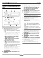
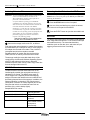
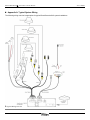
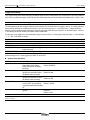
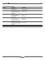
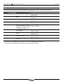
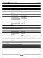
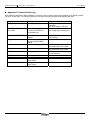
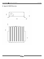
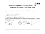
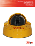
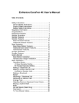
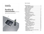
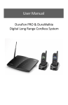
RouteRecorder® 4C Installation Guide July 2009 The main features of the RouteRecorder® 4C system are: MDVR, which features both manual event recording and automatic input trigger recording for 7 input triggers, plus a vehicle ignition trigger that automatically powers up the RouteRecorder® 4C system Safety Vision RouteRecorder® 4C Mobile Digital Video Recorder System Installation Guide 2.5-inch removable hard drive that stores recorded data in standard PC file format. Embedded software that: y Authenticates the integrity of archived video files y Automatically calculates remaining recording capacity y Logs input trigger and event data along with recorded image frames in data files Allows on-screen programming for user-selectable items such as video resolution and frame rate (onscreen programming requires a monitor, which is not provided) 4 camera inputs Supplied and Optional Hardware Two access door lock keys are provided with each RouteRecorder® 4C. Overview The Safety Vision RouteRecorder® 4C Mobile Digital Video Recorder with Removable Hard Drive is designed for mobile digital video recording in rugged automotive conditions and can be used to upgrade obsolete analog technology in existing mobile VCR observation systems. The 2.5-inch removable MDVR hard drive stores files in standard PC file format that can be viewed and archived via a PC connected to a hard drive reader. Programming options and on-screen display settings can be defined by the user to meet individual requirements. Each MDVR requires a removable hard drive. Removable hard drives of various sizes are available. Optional installation hardware kits are available for surface-mount, flush-mount, and console installations. A hard drive reader (for connecting the hard drive to a desktop or notebook PC) is available as an option. In addition, optional peripheral components such as cameras, monitors, and microphones, are available. The RouteRecorder® 4C Mobile Digital Video Recorder (MDVR) records meta-data in addition to each individual video frame. Meta-data includes system information such as the date and time and the status of user-defined input triggers. Optional peripheral components such as cameras, monitors, and microphones are available separately. Copyright © 2009 Safety Vision, L.P. All rights reserved. Safety Vision and the Safety Vision logo are trademarks of Safety Vision, L.P. Notice to Users: This document is confidential and contains proprietary information belonging to Safety Vision, L.P. This document and the information contained herein cannot be distributed, communicated, reproduced, altered, or disseminated by any means, in whole or in part, without the express written consent of Safety Vision, L.P. Possession of this document constitutes the user’s acceptance of these nondisclosure covenants. The information in this document is believed to be accurate in all respects. However, Safety Vision cannot assume responsibility for any consequences resulting from the use thereof. The information contained herein is subject to change without notice. Revisions or new editions to this publication may be issued to incorporate such changes. Safety Vision ▪ 6100 West Sam Houston Parkway North ▪ Houston, Texas 77041 ▪ USA ROUTERECORDER 4C IG Ver 1.3.docx 1 RouteRecorder® 4C Installation Guide System Components Components of the RouteRecorder® 4C system are as follows: MDVR July 2009 D1 RHD SLOT—accepts a removable hard drive (RHD) that stores recorded audio/video files D2 DATA/POWER LEDs—yellow LED (on the left) lights when data is being written to the removable hard drive; green LED (on the right) lights when the removable hard drive is powered on. D3 EJECT BUTTON—ejects the removable hard drive E F RECORD BUTTON—starts manual recording STOP BUTTON—stops playback video and resumes the live view CAUTION: To prevent corruption of the hard drive, press the STOP button BEFORE removing the hard drive. G PAUSE BUTTON—pauses playback video (or resumes paused video playback) H POWER BUTTON—has the following functions: When pressed and released, manually powers the MDVR ON or OFF NOTE: In typical installations, the MDVR is powered ON and OFF automatically by the vehicle-ignition sensor. When it has been powered ON manually, the MDVR remains ON until the POWER button is pressed again. When the MDVR is already ON because it has been triggered by a sensor and recording, the POWER button is disabled. Ï MDVR (Part Number SV-4CHDDVR) A B DIRECTIONAL BUTTONS—have the following functions, depending on the current mode: When video is being played back at normal speed (1X): y UP—cycles up from Channel 1 through Channel 4 and the quad view for audio/video output y DOWN— cycles down from Channel 4 through Channel 1 and the quad view for audio/video output y LEFT—adjusts fast-reverse video playback speed to a maximum of 90X y RIGHT—adjusts fast-forward video playback speed to a maximum of 90X When playback video is paused: y LEFT—reverses video playback one frame at a time y RIGHT—advances video playback one frame at a time When video is not being played back, these buttons move the cursor through on-screen menu selections, and the RIGHT button functions as an ENTER key by confirming menu selections. When the DVR is in Record or Standby mode, the UP and DOWN directional buttons are used to cycle input between Channel 1 through Channel 4 and the quad view ACCESS DOOR LOCK—allows key access to the hard drive slot ROUTERECORDER 4C IG Ver 1.3.docx I J SEARCH/MENU BUTTON—when pressed and released, initiates display of the Search menu for audio/video files stored on the hard drive; when pressed and held for 3 seconds, initiates display of the Main menu AUDIO/VIDEO INPUT—accepts the SV-4CTHRNS wiring harness K TRIGGER INPUT—accepts the SV-4CSENHRNS wiring harness L ETHERNET PORT—accepts the RJ45 connector of an optional Ethernet cable; can be used to download files through a wired or wireless Ethernet connection M GPS RECEPTACLE— (optional) accepts the connector for the GPS module N FAN—cools the MDVR by maintaining air flow 2 RouteRecorder® 4C Installation Guide July 2009 Important Installation Precautions Keep the following precautions in mind when installing the RouteRecorder® 4C system: IMPORTANT: To reduce the risk of electrical shock, disconnect the vehicle negative battery terminal during RouteRecorder® 4C system installation. To prevent system damage, the main wiring harness (Part Number SV-4CSENHRNS) must not be connected to the vehicle electrical system until all other components and cables are installed and connected. The ground wire of the main wiring harness (Part Number SV-4CTHRNS) must be connected directly to the vehicle chassis. Use care when affixing any device to a vehicle with screws. Before drilling or inserting screws, ensure that vehicle components such as the gas tank and airbags will not be damaged by the drill bit or screw. Ï Flush-Mount Installation To prevent system damage, use only the cables supplied with the RouteRecorder® 4C system. Do not disassemble any component of the RouteRecorder® 4C system. Typical Installation 1. Select an appropriate mounting location for the MDVR. 2. Refer to the following illustrations for: Surface-mount installation Flush-mount installation Installation using the VCR Lockbox Adapter Bracket Ï SV-DVR-LB2 Installation NOTE: When mounting the RouteRecorder 4C unit in the SV-DVR-LB2 lockbox as shown above, use the holes provided in order to ensure access to the hard drive. When mounting the RouteRecorder 4C “upside down” in the SV-DVR-LB2 lockbox, use the slots provided and adjust the unit’s position accordingly. 3. Connect system and peripheral devices to the MDVR as directed in documentation for the devices. Connecting Components When connecting components, select inconspicuous cable routes that do not interfere with driver or passenger mobility and that prevent damage to the cables Ï Surface-Mount Installation ROUTERECORDER 4C IG Ver 1.3.docx Refer to Appendix A for illustrations of typical system wiring and component connections of the main wiring harness (Part Number SV-4CTHRNS). 3 RouteRecorder® 4C Installation Guide Main Wiring Harness Connection to MDVR Pin configuration for the 36-pin connector of the MDVR main wiring harness is as follows: Pin 1 3 5 7 9 11 13 15 17 19 21 23 25 27 29 31 33 35 Pin Function Ground Ground Ground Ground Ground Ground Ground Ground Ground Ground Ground Ground -12V Camera 1 -12V Camera 2 -12V Camera 3 -12V Camera 4 Main Power (-) Main Power (-) Pin 2 4 6 8 10 12 14 16 18 20 22 24 26 28 30 32 34 36 Pin Function Left Audio Out Right Audio Out Video Out Ignition Audio In 1 Video In 1 Audio In 2 Video In 2 Audio In 3 Video In 3 Audio In 4 Video In 4 +12V Camera 1 +12V Camera 2 +12V Camera 3 +12V Camera 4 Main Power (+) Main Power (+) ROUTERECORDER 4C IG Ver 1.3.docx July 2009 Sensor Wire Harness Connection to MDVR Pin configuration for the 24-pin connector of the MDVR sensor wire harness is as follows: Pin 1 3 5 7 9 11 13 15 17 19 21 23 Pin Function Ground Ground Not used Not used Ground Serial 1 Transmit Serial 1 Receive Ground Serial 2 Transmit Serial 2 Receive Ground Ignition Input Indication *NOTE: Pin 2 4 6 8 10 12 14 16 18 20 22 24 Pin Function Trigger 1 Trigger 2 Trigger 3 Trigger 4 Trigger 5 Trigger 6 Trigger 7 GP output 1* GP output 2* 12V out (current limited) Ground Not used See Comments section in System Setup Menu section. 4 RouteRecorder® 4C Installation Guide Initial Setup To manually input setup options, an optional monitor must be connected. See associated monitor documentation for details on connecting a monitor. July 2009 Title Setup Menu y System Name: Safety Vision 4C y Triggers 1 through 7: User specified Trigger Setup Menu To initiate display of the Main menu, press and hold the SEARCH/MENU button on the front panel of the MDVR for 3 seconds. y T1: DISPLAY, HIGH Use the UP and DOWN buttons to move the cursor through on-screen menu selections. Use the RIGHT directional button as the “Enter” key. y T3: DISPLAY, HIGH When you have finished setting up a menu item, press the SEARCH/MENU button again to save the changes. y T6: MARK EVENT, HIGH NOTE: After several minutes of inactivity, the menu is no longer displayed, and the SEARCH/MENU button must be pressed again to initiate display of the main menu again. y T2: DISPLAY, HIGH y T4: DISPLAY, HIGH y T5: DISPLAY, HIGH y T7: DISPLAY, LOW y Ignition Setup: Record Control: ENABLE Record Start Delay: 0 MIN Record Stop Delay: 5 MIN Power Off Delay: 1 MIN Main Menu The main menu includes the following menus: Communication Setup y Comm. 1 and 2 Setup System Setup Baud Rate: 9600 Title Setup Parity: none Trigger Setup Data Bits: 8 Communication (Comm.) Setup Stop Bits: 1 Camera 1-4 Setup Protocol: VISCA GPS Setup One Touch Zoom: 75 PCT System Info Focus: AUTO For detailed information about these menus, refer to Appendix B. Sensitivity: LOW Typical Installation Settings These settings are valid for most typical RouteRecorder® 4C installations: System Setup Menu y OSD: ENABLE y Record Mode: STOP y Units: ENGLISH y GP Out 1 Mode: RECORD y GP Out 2 Mode: RECORD y Time Setup: Default value for Daylight Saving Time is ON Slow Shutter: OFF Camera 1-4 Setup Menu y Frame Rate: 30 fps y Image Size: QVGA y Image Quality: MEDIUM y Audio: ON y Audio Volume: 6dB GPS Setup Menu y Use GPS: YES y Use GPS Time: YES y UTC/Local Time: -6 y GPS Data Format: DDD:HH:SS y Password Setup: Default value for Password is 123456; default value for the password requirement is DISABLED for all 4 levels of operation. ROUTERECORDER 4C IG Ver 1.3.docx 5 RouteRecorder® 4C Installation Guide Basic Operation The RouteRecorder® 4C system is initially configured to power up and record automatically when the vehicle ignition is on. When configured for event-based recording, it is not necessary for the driver to turn the system on or to manually initiate or stop recording. However, a user can start and stop a recording manually and can control the system as follows: July 2009 Searching For and Playing Back Video The MDVR can be used to control playback when an optional monitor is installed. See associated monitor documentation for details on connecting a monitor. ~ To search for and play back video, press and release the SEARCH/MENU button to display the Video Search screen on the system monitor, as follows: Manual MDVR Recording To start a recording manually, press the RECORD button on the front panel of the MDVR. To stop, press the STOP button. Switching Audio/Video Input When the DVR is in Record or Standby mode, use the UP and DOWN directional buttons on the front panel of the MDVR to switch input between Channel 1, 2, 3, 4, or the Quad View. MDVR Recording Capacity The recording capacity of the MDVR depends on the following user-selectable factors: Frame rate (30 fps to 1 fps) Image quality (high, medium high, medium, medium low, or low) Image resolution (720 x480, 640 x480, 360 x 240, or 320 x240 pixels) Storage capacity of the hard drive Marking an Event with the Event Button An event can be marked manually with the optional Event Button (SV-MDVR-EB-HRNS). Press the button once to mark an event. When the files are viewed at a later date, file names with a marked event appear with a pound sign (#). NOTE: See the MDVR File Format section on more information on file names. The Event Button must be connected to a Trigger wire, and that trigger must be configured to mark an event. See Appendix A: Typical System Wiring and Appendix B: Setup Menus for me information. ROUTERECORDER 4C IG Ver 1.3.docx Left column displays the dates for which video files have been recorded Right column displays the starting time for each video file recorded on the date selected ~ Use the directional buttons on the front panel of the MDVR to select the date in COLUMN A and the appropriate starting time in COLUMN B. Press the RIGHT button to play the selected video file. ~ During playback, use the MDVR directional buttons as follows: LEFT button adjusts fast-reverse speed to a maximum of 90X. RIGHT button adjusts fast-forward speed to a maximum of 90X. UP and DOWN buttons select Channel 1, 2, 3, 4, or the Quad View for audio/video output (only when video is being played back at normal speed [1X]) 6 RouteRecorder® 4C Installation Guide July 2009 Archiving Video to a PC Removing the Hard Drive from the MDVR WARNING: To prevent hard drive damage and loss of data stored on the removable hard drive, DO NOT use the Microsoft Windows operating system of the PC to format the removable hard drive. Use of the Windows operating system FORMAT command on the removable hard drive will erase all data stored on the removable hard drive and make the removable hard drive unusable in the MDVR. Furthermore, on some PCs, the operating system may not automatically recognize the removable hard drive, in which case the operating system will prompt the user about whether the unrecognized drive should be formatted. If appropriate, click the NO button in response to the following prompt: THE DISK IN DRIVE X IS NOT FORMATTED. DO YOU WANT TO FORMAT IT NOW? CAUTION: To prevent corruption of the hard drive, press the STOP button on the front panel of the MDVR panel BEFORE removing the hard drive. ~ Connect the storage media to the PC, as follows: First connect the optional hard drive reader (Part Number SV-HDREADER) to a USB port on the PC. Next, plug the AC adapter into the hard drive reader. Then, insert the removable hard drive that contains recorded RouteRecorder® 4C system files into the hard drive reader, and turn on the key of the hard drive reader. ~ Press the STOP button on the front panel ~ Use one of the provided keys to unlock the access door lock on the front panel of the MDVR. ~ Press the EJECT button to eject the removable hard drive. Meta-Data The MDVR generates system information (meta-data) for each image frame and stores it on the archive media (the removable hard drive). The meta-data describes conditions (such as the date, time, and status of input triggers) present at the time of recording. The storage media (the removable hard drive) will be recognized by the Microsoft Windows Operating System of the PC and assigned a drive letter in Microsoft Windows Explorer, which can be used to copy video files from the storage media to the PC. MDVR File Format The MDVR stores recorded audio/video files on the installed archive media (the removable hard drive) in standard PC file format. The MDVR saves each 10minute segment in a separate file and automatically assigns a filename that identifies the source MDVR and the starting date and time of the segment. In addition, the filename identifies “continuation” files (files that are a continuation of another 10-minute segment) and “event” files (files that include a user-defined event such as activation of the vehicle backup lights). Sample MDVR file names: Mar.12.2008-17.36.48-001.avi Mar.12.2008-17.36.48#-002.avi Mar.12.2008-17.36.48#-003.avi Mar.12.2008-17.36.48-004.avi Record button manually pressed Trigger event occurred Another event occurred No event occurred, DVR created next file in sequence automatically ROUTERECORDER 4C IG Ver 1.3.docx 7 RouteRecorder® 4C Installation Guide July 2009 On-Screen Display Remote MDVR Access Through FTP When recorded video is being played back or live video is being displayed on the optional monitor, meta-data is displayed on-screen as follows: The MDVR supports FTP commands in MS-DOS as follows: Cd (changes directory) Dir (displays a directory listing) Ls (lists the contents of the directory) Get (gets a file from the MDVR) Delete (deletes a file from the MDVR) Rmdir (removes a directory from the MDVR) WARNING: Use the Rmdir command with caution. The MDVR does not verify that a directory is empty before allowing the directory to be deleted. In addition, using the Rmdir command to delete a directory that is not empty causes space on the removable hard drive to become unavailable for use. A TIME—displays the time in HH:MM:SS format (the time is set by the user during initial setup and then maintained by the MDVR) B MDVR STATUS—displays the current mode of the MDVR (Stop, Record, Playback [and Playback Speed], or Pause) C CURRENT INPUT—displays CH1-CH4 (channel 1-4), no display for the Quad View D ACTIVE TRIGGER—displays the trigger that started recording activity E DATE—displays the date in MM/DD/YY format (the date is set by the user during initial setup and then maintained by the MDVR) F ACCELEROMETER and RADAR SPEED G GPS COORDINATES H MDVR NAME—displays the user-definable MDVR name ROUTERECORDER 4C IG Ver 1.3.docx System Health Logs Log files are created and placed in the hard drive’s SYSTEM\SYSLOG folder. To prevent a file system error from corrupting all log files, the logging system will fill 10 files in rotation with the oldest file deleted when necessary. A new file is created if the file reaches 512 records, a new day, or the system is turned off and on again. Each file has a date stamp in the filename and can be viewed in date order. See Appendix C: System Health Logs for more information. 8 RouteRecorder® 4C Installation Guide July 2009 Specifications MDVR Specifications Part Number SV-4CHDDVR Item Power Supply Input Rating Power Consumption Video System Video Compression Video Resolution Frame Rate File Format Archive Media Type Typical Recording Time Operating Temperature Dimensions Width x Depth x Height Weight External Trigger Inputs Operating Vibration Transient Protection Supplied Accessories Specification 8 ~ 24 VDC (standard automotive power range) When ON: < 470 mA (without cameras) When OFF: < 10 mA NTSC Motion JPEG compression (5 userselectable compression ratios) User-selectable: 720 x480, 640 x480, 360 x 240, or 320 x240 User-selectable: 30 fps to 1/1 fps [time-lapse] 8 channel AVI (4 video, 4 audio) (can be played with Microsoft Windows Media Player) 2.5-inch hard drive 80-GB Hard Drive: 92 to 132 hours 120-GB Hard Drive: 130 to 200 hours 41°F ~ 131°F (0°C ~ 55°C) 7 x 8 x 2 inches 178 x 203 x 51 mm 4.5 lbs (2 kg) 7 trigger inputs in addition to the vehicle ignition trigger input Linear 5-300 Hz, 1.0G (0 to peak) 2500 watts for 10 m/s Access door lock keys (2) ROUTERECORDER 4C IG Ver 1.3.docx 9 RouteRecorder® 4C Installation Guide July 2009 Obtaining Warranty Service Warranty Information LIMITED 1-YEAR NEW PRODUCT WARRANTY Safety Vision, L.P. (“SV”) makes the following limited warranty, which is effective at the time of the original enduser purchase. NOTE: Optional warranty products are available for all SV products and may be purchased at the time of the original end-user purchase or any time during the original Limited 1-Year New Product Warranty period. To obtain warranty service, the customer must contact the SV Service and Warranty Manager at 713.896.6600 or 800.880.8855 to report a defective product. (The customer must report the model number and serial number if available.) The Service and Warranty Manager will assist in troubleshooting the problem and, if necessary, issue a return material authorization (RMA) number. The customer must include this number on the outside of each package shipped to SV. Important Packing and Shipping Instructions SV warrants this product against defects in materials for a period of 1 year after the date of purchase. During this period, SV will repair or replace a defective product or part without charge to the customer. The customer must send the defective product or part to SV or an authorized SV dealer. The customer must pay for all transportation and insurance charges for sending the unit to be repaired. SV’s total liability is limited to the original product cost. When a product requires service, only the affected component must be returned. The customer must use proper packing material to ensure against damage during shipping. Any shipping damage caused by improper packing is not covered under this warranty. In addition, the customer must include a return material authorization (RMA) number on the outside of each package shipped to SV and a letter explaining the defect with the product. Installation Guide How to Reach Us The customer should thoroughly read this guide before operating this product. If you have exhausted the information in this document and require further assistance or information, please contact Safety Vision toll-free at 1-800-880-8855 or send an e-mail message requesting assistance to: [email protected]. Customer’s Responsibility The above warranty is subject to the following conditions: Customer must notify SV within 10 days of discovering the defective product or part and provide a description of the defect and complete information about the manner of its discovery. All warranty servicing of this product must be performed by SV or an authorized servicing agent. Warranty extends only to defects in materials as limited above. Warranty does not extend to any product or part that has been lost or discarded by the customer; to damage to products or parts caused by misuse, accident, improper installation, improper maintenance, or use in violation of instructions furnished with the product; to units that have been altered or modified without authorization of SV; to damage to products or parts thereof that have had the serial number removed, altered, defaced, or rendered illegible; or to any failure of the product to function caused by burglary, fire, flood, war, riot, civil commotion, Acts of God, or any other condition beyond the control of SV. ROUTERECORDER 4C IG Ver 1.3.docx Document Change Log Document Version Document Filename Date Changes Made 1.0 ROUTERECORDER 4C IG VER 1.0.DOC July 2008 New document 1.2 ‘’ Feb 09 Updated to reflect changes in firmware 1.3 “ July 09 Updated SV-DVRLB2 diagram 10 RouteRecorder® 4C Installation Guide July 2009 Appendix A: Typical System Wiring The following wiring overview is appropriate for typical RouteRecorder® 4C system installations. Ï Typical Wiring Overview ROUTERECORDER 4C IG Ver 1.3.docx 11 RouteRecorder® 4C Installation Guide July 2009 Appendix B: Setup Menus The main menu includes the following menus: System Setup Title Setup Trigger Setup Communication (Comm.) Setup Camera 1-4 Setup GPS Setup System Info System Setup Menu The System Setup menu allows user configuration as follows: Menu Item OSD Record Mode Units Description Turns the On Screen Display on or off Selects continuous recording or trigger-based recording (Stop) Controls the standard of measurement Comments Values: ENABLE, DISABLE Default: ENABLE Values: CONTINUOUS, STOP Default: STOP Values: ENGLISH, METRIC Default: ENGLISH Values: POWER (unit powered on) RECORD (recording) PLAY (playing back footage) SPEED (speed exceeds limit set in GPS Setup Menu) ACCEL (acceleration exceeds limit set in GPS Setup Menu) T1-T7 (when HIGH state voltage is applied to indicated triggers) USER_CONTROL (trigger command made using telnet protocol) DISK_FULL (disk full, recording stopped) TRIGGER_ACTIVE (any trigger is activates) Default for GP Out 1 Mode: RECORD Default for GP Out Mode: POWER Default value for Daylight Saving Time is ON GP Out 1, 2 Mode General purpose 12V outputs indicate a number of MDVR events (see Comments) Time Setup Displays the menu that controls the system date, time, timezone, Daylight Saving Time, and 12 or 24 hour formats Displays the File Setup Menu Menu items: that allows the user to define Max File Time (10 minute default) the maximum recorded file size Max File Size (1024 MB default) by time and file size. File Setup ROUTERECORDER 4C IG Ver 1.3.docx 12 RouteRecorder® 4C Installation Guide Menu Item Password Setup Advanced Setup Description Allows user to set a password that is required when performing certain activities with the MDVR; password allows use of designated activity for 30 minutes or until power is cycled Initiates display of the Advanced Setup menu July 2009 Comments The MDVR prompts for password input when it is powered up initially. The default password is 123456. The password may contain any upper- or lowercase letters in addition to numbers and the symbols “-“ and “@”. The requirement for a password can be enabled or disabled for 4 levels of operation as follows: All Keys Power-off Playback Menus Menu items: Restore Defaults (restores factory default settings) Disk to Erase (selects target for Erase Media and Format Media options) Erase Media (Permanently deletes all recorded data except for the system directory Format Media (Permanently deletes all recorded data and installs a DVR file system – use when “No Disk” error appears despite installed disk) Network Setup (See following “Network Setup Sub-Menu” section.) Network Setup Sub-Menu Menu Item IP Address: Subnet Mask: FTP Username FTP Password Save Description MDVR network address (requires power cycle to take effect) Used to determine the subnet to which MDVR IP address belongs (requires power cycle to take effect) Case-sensitive user name used when connecting with a web browser Case-sensitive password used when connecting with a web browser Saves network setup information ROUTERECORDER 4C IG Ver 1.3.docx Comments User-selectable User-selectable Default: USER Default: PASS N/A 13 RouteRecorder® 4C Installation Guide July 2009 Title Setup Menu The Title Setup menu allows user naming of the MDVR and input triggers (for inclusion in meta-data and on-screen display) as follows: Menu Item System Name Trigger 1 through Trigger 7 Description Default MDVR3xx Allows user input of a 14character alphanumeric MDVR name N/A Allows user input of a 4-character alphanumeric name for Triggers 1 through 7, respectively ROUTERECORDER 4C IG Ver 1.3.docx 14 RouteRecorder® 4C Installation Guide July 2009 Trigger Setup Menu The Trigger Setup menu allows assigning an MDVR response and a voltage state ([ACTIVE] HIGH or [ACTIVE] LOW) for each of the user-defined triggers, as well as the GPS-detected speed and accelerometer thresholds on the X and Y axes. NOTE:The accelerometer and speed triggers are only available on units equipped with the GPS option. The mask associated with a trigger indicates which cameras are recorded when the trigger is active. The mask indicates directly which cameras are recorded so a mask of “123” will record cameras 1, 2, and 3 and not 4. Trigger masks are additive such that multiple trigger activations create an aggregate mask that is the logical or of all active masks. Camera 1 must always be active, therefore all masks contain camera one. For example, if two triggers are activated where trigger 1 has the mask “13” and trigger 2 has the mask “4”, then cameras “1”, “3”, and “4” will all be recorded. MDVR Response DISPLAY MARK RECORD START [RECORD] STOP [RECORD] Description Indicates trigger activity in on-screen display and in meta-data Starts a recording if the MDVR is not already recording and indicates an event in the filename Starts a recording when trigger is activated and stops it when trigger is no longer activated Starts a recording when trigger is activated but does not stop the recording when trigger is no longer activated Stops a recording when trigger is activated Default settings for all 7 input triggers are DISPLAY and HIGH. Ignition Setup Sub-Menu Menu Item Record Control Record Start Delay Record Stop Delay Power Off Delay Camera Select Description Enables or disables the Record Start Delay, Record Stop Delay, and Power Off Delay functions Delay time from when the ignition is turned ON to when the MDVR starts recording Delay time from when the ignition is turned OFF to when the MDVR stops recording Delay time from when ignition is turned OFF and recording stopped and the MDVR powers off. Mask of cameras to record on ignition Comments Values: ENABLE, DISABLE Default: ENABLE Values: 0 MIN to 60 MIN Default: 0 MIN Values: 0 MIN to 60 MIN Default: 0 MIN Values: -1 MIN to 60 MIN (see Caution) Default: 10 MIN Values: Any combination of cameras 1-4, must always include Camera 1 Default: 1234 CAUTION: Setting the Power Off Delay value to ‘-1’ keeps the MDVR on indefinitely until power is removed. This will run down a vehicle’s battery. ROUTERECORDER 4C IG Ver 1.3.docx 15 RouteRecorder® 4C Installation Guide July 2009 Speed/Accel. Setup Sub-Menu Menu Item Speed Description GPS-detected speed at which recording begins Speed Dwell Time for which recording lasts once Speed (as set in the previous item) has been surpassed Amount of G (gravitational force) detected by the accelerometer on the X axis (side-to-side) Amount of G (gravitational force) detected by the accelerometer on the Y axis (backwards and forwards) Time for which recording lasts once Accel. X or Y (as set in the previous items) has been surpassed Accel. X Accel. Y Accel. Dwell Comments Values: ENABLE, DISABLE Default: 52 MPH Values: 0 MIN to 60 MIN Default: 5 MIN Values: 1.0 to 10.9 G Default: 1.0 G (see Note) Values: 1.0 to 10.9 G Default: 1.0 G (see Note) Values: 0 MIN to 60 MIN Default: 5 MIN NOTE: The accelerometer values are absolute. A setting of 5.0 G will trigger an event when both 5.0 G and -5.0 G is reached. ROUTERECORDER 4C IG Ver 1.3.docx 16 RouteRecorder® 4C Installation Guide July 2009 Communication (Comm.) Setup Menu The Communication (Comm.) Setup menu allows user configuration of Comm. 1 and Comm. 2 as follows: Menu Item Baud Rate Parity Data Bits Stop Bits Protocol One Touch Zoom* Focus** Sensitivity** Slow Shutter** Description Selects the baud transfer rate Comments Values: 4800, 9600, 38400 Default: 9600 Selects none, even, or odd Values: none, even, odd parity Default: none Selects number of data bits Values: 5, 6, 7, 8, 9 Default: 8 Selects number of stop bits Values: 1, 2 Default: 1 Selects the protocol to be used Values: NONE, VISCA (Sony), COSTAR with zoom cameras; Note that Default: COSTAR Safety Vision supplies a Sony forward-facing camera Selects the percentage of Values: zoom applied Default: 100 PCT Selects infinite or automatic Values: AUTO, INFINITY focus Default: AUTO Selects how sensitive the Values: HIGH, LOW camera is to light Default: LOW Turns the slow shutter feature Values: ON, OFF on or off Default: OFF * This option only appears when VISCA or COSTAR is selected as the Protocol. ** These options only appear when VISCA is selected as the Protocol. ROUTERECORDER 4C IG Ver 1.3.docx 17 RouteRecorder® 4C Installation Guide July 2009 Camera 1-4 Setup Menu The Camera 1-4 Setup menu displays camera setup information as follows: Menu Item Camera State Frame Rate Image Size Image Quality Audio Audio Volume Description Enables camera to be recorded (Camera 1 is always enabled) Adjusts the frame rate of the selected camera in frames per second Selects the image resolution of the selected camera Adjusts the compression rate of the selected camera; Lower image quality equates to increased record times and vice versa Selects if audio is recorded Adjusts the volume at which audio is recorded in decibels (dB) Comments Values: ENABLED, DISABLED Default: ENABLED Values: DISABLED, 1, 5, 7.5 10, 15, 30, CUSTOM* Default: 30 fps Values: D1 (720 x 480), VGA (640 x 480), QD1 (360 x 204), QVGA (320 x 240) Default: QVGA Values: HIGH, MEDIUM HIGH, MEDIUM, MEDIUM LOW, LOW, CUSTOM* Default: MEDIUM Values: ON, OFF Default: ON Values: 0db, 3db, 6db, 9db, 12db, -12db, -9db, -6db, -3db Default: 12db * CUSTOM is set via telnet command GPS Setup Menu The GPS Setup menu displays system information as follows: Menu Item Use GPS Use GPS Time GPS Data Format Calibrate Accel Description Specifies whether the DVR records GPS information Specifies whether the DVR time is set automatically by GPS module Selects the on-screen display format for GPS information Resets accelerometers to 0 Gs at the current mounted orientation Comments Values: Yes or No Default: Yes Values: Yes or No Default: Yes Values: DDD:MM:SS (degrees: minutes: seconds) DDD:MM:mm (degrees: minutes: decimal minutes) DDD.ddddd (degrees: decimal degrees) N/A System Info Menu The System Info menu displays system information as follows: Menu Item Disk Size Pct (Percent) Used Pct (Percent) Free Version Mac Address Description Storage capacity of the removable hard drive Percentage of used space on the removable hard drive Percentage of free space on the removable hard drive Firmware version level MAC (media access control) address of the DVR ROUTERECORDER 4C IG Ver 1.3.docx 18 RouteRecorder® 4C Installation Guide July 2009 Appendix C: System Health Logs Each health log displays the date in MM.DD.YY format, the time in 24-hour format, the IP address of the MDVR, and the log name, in that order. The following table lists all log names and the information that appears after them. Log Name SYSTEM INFORMATION Meaning System operating normal SYSTEM UNDER VOLTAGE Low input voltage going below 9v threshold and when it comes above 10v CAMERA INPUT ERROR ACCX Video signal not present on channel User configured trigger name is reported at each state change Acceleration trigger activated ACCY Acceleration trigger activated SPD Speed trigger set POWER ON START IGN MEDIA_READ_ERROR Unit has booted Ignition trigger state Reading from media storage device failed Writing to media storage device failed Trigger Name MEDIA_WRITE_ERROR ROUTERECORDER 4C IG Ver 1.3.docx Parameter reported p1: Degrees Celsius of processor p2: Input voltage in millivolts p1: Not used p2: Voltage value causing error p1: Camera ID p2: Not used NONE USED p1: Not used p2: Acceleration value x1000 p1: Not used p2: Acceleration value x1000 p1: Not used p2: Speed value None None None None 19 RouteRecorder® 4C Installation Guide July 2009 Appendix D: MDVR Dimensions ROUTERECORDER 4C IG Ver 1.3.docx 20