1
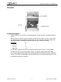
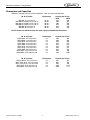
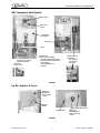
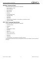
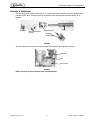
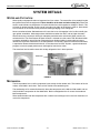
®
CORNELIUS ICE MAKERS
Training Manual
IMD 600-90
Front End Assembly
Release Date: March 14, 2003
Publication Number: TP00967
Revision Date: June 18, 2003
Revision: B
Visit the IMI Cornelius web site at www.cornelius.com for all your Literature needs.
CORNELIUS ICE MAKERS
TRAINING MANUAL
The products, technical information, and instructions contained in this manual are subject
to change without notice. These instructions are not intended to cover all details or variations of the equipment, nor to provide for every possible contingency in the installation,
operation or maintenance of this equipment. This manual assumes that the person(s)
working on the equipment have been trained and are skilled in working with electrical,
plumbing, pneumatic, and mechanical equipment. It is assumed that appropriate safety
precautions are taken and that all local safety and construction requirements are being
met, in addition to the information contained in this manual.
To inquire about current revisions of this and other documentation or for assistance with
any Cornelius product contact:
IMI Cornelius Inc.
Corporate Headquarters
One Cornelius Place
Anoka, MN 55303-6234
U.S.A.
Internet:
www.cornelius.com
Email:
[email protected]
In the U.S.A.:
Outside the U.S.A.:
phone:763-421-6120
800-238-3600
FAX:800-535-4231
phone:763-421-6120
FAX:763-422-3297
Trademarks and copyrights:
Aurora, Cornelius, Decade, Hydro Boost, Sitco, Spirit, UF-1, Vanguard, Venture, Olympus,
and Vista are registered trademarks of IMI Cornelius Inc.
Optifill trademark is pending.
This document contains proprietary information and it may not be
reproduced in any way without permission from Cornelius.
Printed in U.S.A.
Copyright © 2003, All Rights Reserved, IMI Cornelius Inc.
TABLE OF CONTENTS
Introduction . . . . . . . . . . . . . . . . . . . . . . . . . . . . . . . . . . . . . . . . . . . . . . . . . . . . . . . . . .
Preview Questions . . . . . . . . . . . . . . . . . . . . . . . . . . . . . . . . . . . . . . . . . . . . . . . . . .
Key Things To Know / Do . . . . . . . . . . . . . . . . . . . . . . . . . . . . . . . . . . . . . . . . . . . . .
Popular Applications . . . . . . . . . . . . . . . . . . . . . . . . . . . . . . . . . . . . . . . . . . . . . . . . .
Principles of Extruded Ice Making . . . . . . . . . . . . . . . . . . . . . . . . . . . . . . . . . . . . . . .
Flake vs Chunklet . . . . . . . . . . . . . . . . . . . . . . . . . . . . . . . . . . . . . . . . . . . . . . . . . . .
Overview . . . . . . . . . . . . . . . . . . . . . . . . . . . . . . . . . . . . . . . . . . . . . . . . . . . . . . . . . .
Product Description . . . . . . . . . . . . . . . . . . . . . . . . . . . . . . . . . . . . . . . . . . . . . . .
Dimensions and Capacities . . . . . . . . . . . . . . . . . . . . . . . . . . . . . . . . . . . . . . . . .
1
1
1
2
2
2
3
3
4
Key Points — IMD / WCC / WCF Ice Makers . . . . . . . . . . . . . . . . . . . . . . . . . . . . . . . .
Superheat & Suction Temperature . . . . . . . . . . . . . . . . . . . . . . . . . . . . . . . . . . . . . .
Evaporator Squealing . . . . . . . . . . . . . . . . . . . . . . . . . . . . . . . . . . . . . . . . . . . . . . . .
Do Not Agitate . . . . . . . . . . . . . . . . . . . . . . . . . . . . . . . . . . . . . . . . . . . . . . . . . . . . . .
Evaporator Efficiency . . . . . . . . . . . . . . . . . . . . . . . . . . . . . . . . . . . . . . . . . . . . . . . .
Water and Air Temperature . . . . . . . . . . . . . . . . . . . . . . . . . . . . . . . . . . . . . . . . . . . .
IMD Component Identification . . . . . . . . . . . . . . . . . . . . . . . . . . . . . . . . . . . . . . .
Ice Bin, Agitator, & Cover . . . . . . . . . . . . . . . . . . . . . . . . . . . . . . . . . . . . . . . . . .
IMD Major Component Detail . . . . . . . . . . . . . . . . . . . . . . . . . . . . . . . . . . . . . . .
WCC / WCF Component Identification . . . . . . . . . . . . . . . . . . . . . . . . . . . . . . . .
Extruder & Evaporator . . . . . . . . . . . . . . . . . . . . . . . . . . . . . . . . . . . . . . . . . . . . .
5
5
5
5
6
6
7
7
8
8
9
System Details . . . . . . . . . . . . . . . . . . . . . . . . . . . . . . . . . . . . . . . . . . . . . . . . . . . . . .
Water and Filtration . . . . . . . . . . . . . . . . . . . . . . . . . . . . . . . . . . . . . . . . . . . . . . . . .
Mechanical . . . . . . . . . . . . . . . . . . . . . . . . . . . . . . . . . . . . . . . . . . . . . . . . . . . . . . .
Refrigeration . . . . . . . . . . . . . . . . . . . . . . . . . . . . . . . . . . . . . . . . . . . . . . . . . . . . . .
Refrigeration System Operation . . . . . . . . . . . . . . . . . . . . . . . . . . . . . . . . . . . .
Remote Units . . . . . . . . . . . . . . . . . . . . . . . . . . . . . . . . . . . . . . . . . . . . . . . . . .
WCC/WCF Controls and Electrical . . . . . . . . . . . . . . . . . . . . . . . . . . . . . . . . . . . . .
IMD Controls and Electrical . . . . . . . . . . . . . . . . . . . . . . . . . . . . . . . . . . . . . . . . . . .
Illuminated Merchandiser (Optional) . . . . . . . . . . . . . . . . . . . . . . . . . . . . . . . . .
Key Switch (Optional) . . . . . . . . . . . . . . . . . . . . . . . . . . . . . . . . . . . . . . . . . . . .
Drink Front (Optional) . . . . . . . . . . . . . . . . . . . . . . . . . . . . . . . . . . . . . . . . . . . .
Auger Delay . . . . . . . . . . . . . . . . . . . . . . . . . . . . . . . . . . . . . . . . . . . . . . . . . . .
Dispense Timer (Solid State Timer) P/N TE1-24X-31796 . . . . . . . . . . . . . . . . .
Stand-by Condition . . . . . . . . . . . . . . . . . . . . . . . . . . . . . . . . . . . . . . . . . . . . . .
Timing Condition . . . . . . . . . . . . . . . . . . . . . . . . . . . . . . . . . . . . . . . . . . . . . . . .
Run Condition . . . . . . . . . . . . . . . . . . . . . . . . . . . . . . . . . . . . . . . . . . . . . . . . . .
Full Bin Condition . . . . . . . . . . . . . . . . . . . . . . . . . . . . . . . . . . . . . . . . . . . . . . .
Test Procedure . . . . . . . . . . . . . . . . . . . . . . . . . . . . . . . . . . . . . . . . . . . . . . . . .
10
10
10
11
11
11
12
16
16
16
16
16
16
16
16
16
16
16
Appendices . . . . . . . . . . . . . . . . . . . . . . . . . . . . . . . . . . . . . . . . . . . . . . . . . . . . . . . . .
Appendix A — Installation Information . . . . . . . . . . . . . . . . . . . . . . . . . . . . . . . . . .
Bin / Dispenser Compatibility . . . . . . . . . . . . . . . . . . . . . . . . . . . . . . . . . . . . . .
Site Requirements . . . . . . . . . . . . . . . . . . . . . . . . . . . . . . . . . . . . . . . . . . . . . . .
18
18
18
18
Installation . . . . . . . . . . . . . . . . . . . . . . . . . . . . . . . . . . . . . . . . . . . . . . . . . . . . .
Appendix B — Evolution of the Chunklet / Flaker Design . . . . . . . . . . . . . . . . . . . .
The Spline Drive . . . . . . . . . . . . . . . . . . . . . . . . . . . . . . . . . . . . . . . . . . . . . . . .
The Pin Drive . . . . . . . . . . . . . . . . . . . . . . . . . . . . . . . . . . . . . . . . . . . . . . . . . .
Current Generation “D” Drive . . . . . . . . . . . . . . . . . . . . . . . . . . . . . . . . . . . . . .
Appendix C — Evaporator Replacement . . . . . . . . . . . . . . . . . . . . . . . . . . . . . . . .
Procedure for WCC / WCF Ice Makers . . . . . . . . . . . . . . . . . . . . . . . . . . . . . . .
18
19
19
19
19
20
20
Troubleshooting . . . . . . . . . . . . . . . . . . . . . . . . . . . . . . . . . . . . . . . . . . . . . . . . . . . . . 21
Gear Motor Overload Condition . . . . . . . . . . . . . . . . . . . . . . . . . . . . . . . . . . . . . . . 21
Review . . . . . . . . . . . . . . . . . . . . . . . . . . . . . . . . . . . . . . . . . . . . . . . . . . . . . . . . . . . . . 22
Cornelius Ice Makers Training Manual
INTRODUCTION
PREVIEW QUESTIONS
Check your current knowledge by taking a few minutes to answer the following questions:
1.
2.
3.
4.
How many thrust bearings are in each IMD/WCC/WCF unit?
__________________________________________________________________
__________________________________________________________________
How many manual reset overloads are in each IMD/WCC/WCF unit(s)?
__________________________________________________________________
__________________________________________________________________
What type of water filters should be used on a Wilshire Ice Maker?
__________________________________________________________________
__________________________________________________________________
What is the difference between Cubed and Extruded Ice Makers?
__________________________________________________________________
__________________________________________________________________
KEY THINGS TO KNOW / DO
•
Rotational Freeze is the primary cause of evaporator squealing noises in units.
•
What is the proper water level setting.
•
How do you adjust low water safety switch.
•
How do you adjust ice level switch on IMD Series.
•
Why are there vertical groves (sanding) on the interior wall of the evaporator.
•
Water quality is very important!
•
Understanding control and safety switches!
•
Refrigeration gauges used only when absolutely necessary!
•
On the larger IMD units it is important to understand the function of the dispense timer.
© 2003, IMI Cornelius Inc.
-1-
Publication Number: TP00967
Cornelius Ice Makers Training Manual
POPULAR APPLICATIONS
Because of their unique form of ice and their extremely compact size, the Cornelius/Wilshire ice maker
has a wide range of popular applications. The IMD model line has found wide acceptance in the convenience store market, where it provides a compact package with no need for the counter person to refill
the ice bin. The U.S. Navy has found the IMD to be an excellent choice for its on board food service
requirements and other applications including hospitals, cafeterias, and nursing stations.
The WCC/WCF series is also being used in restaurants and the meat packing industry. The WCF series
has met with success because of the particularly high quality of the flake ice it produces.
Because of the chewable nature of the Chunklet ice produced by the IMD and WCC ice makers, the ice
has been very popular with consumers wherever it is available.
PRINCIPLES OF EXTRUDED ICE MAKING
The Wilshire ice maker creates ice in a process called extrusion. The ice is frozen to an evaporator wall
until it grows thick enough to harvest. At that point the ice is shaved from the wall by an auger and carried
upward toward the extruding head. The extruding head is a finned device that forms or compresses the
ice into its familiar chunklet shape. As the ice is compressed by the head, whatever remaining water
there is on the surface of the ice will be squeezed away leaving a uniformly shaped chunk of ice. The ice
made in this process is soft and edible, yet resists bridging in ice bins. Automatic agitation circuits in cold
plate units or other dispensers should be disabled to prevent the breakdown of the ice.
FLAKE VS CHUNKLET
The WCC and WCF ice makers are virtually the same machine except for the extruding head and bin
control bracket. The primary difference is the amount of compression exerted by the extruding head on
the ice. This is comparable to going outside on a snowy day and scooping up a handful of snow. If the
snow is tossed into the air without compacting it, it will break apart quickly. If the snow is packed into a
ball, it will retain its shape even after striking the ground. The chunklet extruding head in the WCC has a
sharp bend at the top of the channel where the ice is formed. As the ice comes to the top of the head it
must make a sharp turn outward from the head. This bend causes just enough resistance to the upward
flow of the ice to be compacted into a chunklet of ice.
The WCF head bend is very gradual and very little ice compacting occurs. Just enough pressure is
applied for any excess water to be extracted to create a fluffy dry form of true flake ice.
Users of the Cornelius Wilshire bin top ice maker are pleased to know that any WCC can be converted
into a WCF, or the reverse, in just a few minutes. Simply turn off the ice maker and its water supply,
remove the top panel and the top of the auger assembly dispense tray. Pull the auger from the evaporator and disassemble it. Replace the head with the opposite head and restore the parts, power and water
supply and manufacture the preferred type of ice.
NOTE: The IMD Ice Maker/Dispenser cannot be equipped with a flake head. Flake ice will not work
in any dispenser.
Publication Number: TP00967
-2-
© 2003, IMI Cornelius Inc.
Cornelius Ice Makers Training Manual
OVERVIEW
Ice Storage Bin
Ice Chute
Ice Dispensing Lever
FIGURE 1
Product Description
Wilshire Ice Makers are available as ice making dispensers, modular chunklet, and modular flaked ice
makers.
Wilshire Continuous Chunklet (WCC) and Wilshire Continuous Flake (WCF) ice makers come in three
sizes determined by their evaporators inside diameter, (ID). The evaporator’s diameter is used as the
defining measurement, although the height also increases with an increase in diameter.
Designation
ID
•
500 series
2”
•
700 series
2 ½”
•
1000 series
3 ½”
The designation approximates the maximum possible output of the ice maker in a 24-hour period.
The WCF series of ice makers also includes a dual 3 ½” evaporator model called the WCF 2200.
The ice maker dispenser series (IMD) use the numeric description of maximum ice per day and the bin
capacity. For example, the IMD 300-30 makes 300 pounds per day and stores 30 pounds of ice in its bin.
Illuminated merchandisers are optional.
© 2003, IMI Cornelius Inc.
-3-
Publication Number: TP00967
Cornelius Ice Makers Training Manual
Dimensions and Capacities
IMD Units available with A/C or W/C condensers, Lever or Push button dispense.
(W. D. H) Inches
Bin Storage
IMD 300-15, 15 x 24 x 35
IMD 300-30, 18.625 x 27.5 x 35.75
IMD 302-30, 18.625 x 27.5 x 35.75
IMD 600-30, 18.625 x 27.5 x 35.75
IMD 600-30, 24 x 29 x 41
IMD 601-90, 24 x 29 x 41
13 lbs.
30 lbs.
30 lbs.
30 lbs.
90 lbs.
90 lbs.
Capacity lbs./24 hrs.
70/50
90/70
246
202
360
301
300
250
618
493
618
493
618
493
NOTE: Health care IMD Units have the same capacity with different dimensions.
(W. D. H) Inches
WCC 500A, 14.5 x 25 x 24.5
WCC 500W, 14.5 x 25 x 24.5
WCC 501A, 14.5 x 25 x 24.5
WCC 700A, 14.5 x 25 x 24.5
WCC 700W, 14.5 x 25 x 24.5
WCC 701A, 14.5 x 25 x 24.5
WCC 701W, 14.5 x 25 x 24.5
WCC 700R, 14.5 x 25 x 24.5
WCC1001A, W, R, 22 x 24 x 27
WCC2001A, W, R, 30 x 24 x 28
Bin Storage
n/a
n/a
n/a
n/a
n/a
n/a
n/a
n/a
n/a
n/a
Capacity lbs./24 hrs.
369
285
369
285
369
285
616
513
369
513
616
513
369
513
616
513
940
748
1735
1262
(W. D. H) Inches
WCF 510A, W, 14.5 x 25 x 24.5
WCF 710A, W, R, 14.5 x 25 x 24.5
WCF 711A, W, R, 14.5 x 25 x 24.5
WCF1101A, W, R, 22 x 24 x 27
WCC2001A, W, R, 30 x 25 x 28
Bin Storage
n/a
n/a
n/a
n/a
n/a
Capacity lbs./24 hrs.
442
367
892
702
892
702
1426
1134
2280
1711
Publication Number: TP00967
-4-
© 2003, IMI Cornelius Inc.
Cornelius Ice Makers Training Manual
KEY POINTS — IMD / WCC / WCF ICE MAKERS
SUPERHEAT & SUCTION TEMPERATURE
Cornelius/Wilshire IMD/WCC/WCF ice makers run at only 4° F superheat. For this reason they are
equipped with non-adjustable expansion valves.
Suction temperature should be in the 5 to 8 degree below zero temperature range, regardless of refrigerant type.
EVAPORATOR SQUEALING
Squealing noises coming from the evaporator always are accompanied by low production. These noises
are caused by a “rotational freeze”. A rotational freeze is usually caused by mineral buildup on the evaporator wall. These deposits are not always visible, especially when the evaporator is wet. The production
of ice depends on the ice freezing to the wall of the evaporator and being shaved off by the auger.
The evaporator wall is belt sanded to create scratches from top to bottom. These scratches give the ice
something to hold onto, preventing it from rotating with the auger. If the grooves become filled with mineral deposits, the ice will not have any grip on the evaporator and begin to rotate, instead of being
shaved and pushed upward. The squealing noises are caused by the ice continuing to expand as it
rotates.
Ice sticking together in the bin is almost always the result of water chemistry. High concentrates of minerals in the water, chlorine, and salinity are usually found to be the cause. Filters that are specially
designed for ice makers usually contain chemicals called phosphates. These phosphates will prevent
minerals from freezing into the ice in cubers by keeping the particle in suspension and returning it to the
wastewater sump. In the WCC/WCF/IMD ice makers, there is no wastewater; therefore the chemical has
nowhere to go except into the ice bin with the ice. Once there, it behaves like salt, causing the ice to
breakdown and stick together. This can result in damaged agitator blades or a 200-LB block of ice may
be formed in a commercial bin. This effect is less pronounced in the WCF than it is in the WCC or IMD
models. There for phosphate feeders and scale inhibitors should not be used with WCC/WCF or
IMD ice makers.
DO NOT AGITATE
Due to the slightly irregular shape of chunklet ice, it does not require timed agitation to remain loose. It is
an accepted practice to check with the manufacturer of a dispenser before using extruded ice. In some
cases, special agitator blades or bin liners may be required. Automatic agitation circuits must be turned
off or disabled on any dispenser serving extruded ice. If the agitation circuit is enabled it will cause the ice
to breakdown and not dispense properly. Eventually, the agitator blades may be damaged.
© 2003, IMI Cornelius Inc.
-5-
Publication Number: TP00967
Cornelius Ice Makers Training Manual
EVAPORATOR EFFICIENCY
The evaporator on the Cornelius/Wilshire ice maker can be tested for efficiency in three easy ways.
1.
2.
3.
Simply observe the ice coming out of the extruding head during production. As the auger rotates, an
ice chunklet should pop out of each extruder slot on every rotation.
Frost pattern testing of the evaporator. Open up the ice maker so that the auger/extruding head can
be removed. (This may require waiting until the evaporator has thawed out). Remove the assembly
and allow the evaporator to fill with water. Start up the ice maker and allow it to run for exactly one
minute and 45 seconds. Immediately shut the unit down, drain the evaporator or use a flashlight to
look down into the cylinder. A sleeve or spiral of ice should have formed inside the evaporator tube.
This sleeve should extend the full length between the refrigerant inlet and suction outlet lines. There
should be no interruptions, gaps or holes in this pattern. There will not be any ice at either end,
which are beyond the refrigerant lines.
Weighing output. The 24-hour output of the ice maker may be determined by weighing its output of
ice for 15 minutes and multiplying that figure by 96. This figure can also be used to calculate water
usage. The weight of melted ice (water) must be included in either of the above calculations for
accuracy. This test is performed easier on WCC/WCF units than IMDs for obvious reasons. The ice
maker should be allowed to run at least 5 minutes before starting the test.
WATER AND AIR TEMPERATURE
Incoming water temperature and ambient air temperature have a significant effect on ice production.
Contrary to a popular misconception, warm water does not freeze faster than cold water. The incoming
water temperature has a great effect on ice. Combined with a hot ambient temperature, which makes the
condenser less efficient, ice production can be cut back considerably. Inversely, too cold incoming water
or ambient air can produce ice which is so hard that the ice maker will groan and squeak. Water and air
temperature would have to be at 50° F. or lower for this to occur. If placing an ice maker in a cold environment such as a walk-in cooler, it is advisable to select a model with a remote condenser and to protect
the water line from getting too cold.
Publication Number: TP00967
-6-
© 2003, IMI Cornelius Inc.
Cornelius Ice Makers Training Manual
IMD Component Identification
Agitator motor
Bin control
switch
Insulated Ice
storage bin
Evaporator
Motor
Transmission overload
manual reset motor
Water level
control assy.
Transmission
Electrical box including:
- ice making delay timer (45 sec)
- evaporator clear-cut gear motor
timer (90 sec)
- service On/Off switch
- contactor
Compressor start
components:
- start capacitor
- run capacitor
- start relay
FIGURE 2
Ice Bin, Agitator, & Cover
Rubber diaphragm protects ice level
control
Agitator
Blades
Hopper Drain with screen
Dispense Door
Auger and
Extruding Head
Assy inside evaporation
FIGURE 3
© 2003, IMI Cornelius Inc.
-7-
Publication Number: TP00967
Cornelius Ice Makers Training Manual
IMD Major Component Detail
Instructor must explain the function of each component.
•
Dispense Motor - 115 VAC
•
Dispense Solenoid
•
Dispense Button
•
Dispense Timer
•
Bin Switch
•
Low Water Safety Switch
•
Auger Motor Delay
•
Auger Motor
•
Compressor
•
Compressor Start Components - start capacitor, run capacitor, start relay
•
Front End Assembly
WCC / WCF Component Identification
Instructor must explain the function of each component.
•
Front End Assembly
•
Evaporator
•
Auger
•
Extruding Head - bushing
•
Gear Motor
•
Auger Nut
•
Washers - Nylon / Delrin
•
Thermal Expansion Valve
•
Shaft Seal
•
Compressor
•
Start Components - start capacitor, run capacitor, start relay
The compressor electrical box contains the compressor start relay, start capacitor, and run capacitors (if
necessary).
Publication Number: TP00967
-8-
© 2003, IMI Cornelius Inc.
Cornelius Ice Makers Training Manual
Extruder & Evaporator
The extruding head bushing is replacable. It is a special bushing that contains no lead, and needs to be
pressed into the shaft. The thrust bearings will become worn and should be replaced annually or as
needed.
Auger
Auger Nut
Nylon & Delrin thrust
bearings
Extruding head
Extruding
head bushing
FIGURE 4
The seal between the transmission and the evaporator should be replaced when necessary.
Evaporator
Seal
Transmission
FIGURE 5
NOTE: Instructor to pain to manual reset overload location.
© 2003, IMI Cornelius Inc.
-9-
Publication Number: TP00967
Cornelius Ice Makers Training Manual
SYSTEM DETAILS
WATER AND FILTRATION
Water quality and proper filtration are important for all ice makers. The correct filter is key to obtaining the
best performance from the equipment. Filters should be of the taste and odor variety only. Filters that
contain scale inhibitors or phosphates will cause chunklet ice to stick together or “bridge” in the bin. This
will result in agitator damage. As this type of ice maker uses 100% of the w2ater it takes in, those chemicals will remain in the ice and cause pre-mature melting (bridging) in the storage bin.
Never use softened water. Softened water will cause the ice to stick together in the ice bin and will damage agitator assemblies. Water temperature should be no cooler than 50oF and no higher than 90oF.
Warmer water may require pre-chilling for adequate production to be maintained. Water contains dissolved minerals. The measurement of these minerals is referred to as the waters TDS. Dissolved solids
cannot be removed by normal filtration. Removing these dissolved solids is comparable to trying to
remove the sugar from coffee once it has been poured in and stirred. A process called reverse Osmosis
is required to remove the dissolved minerals. In the absence of and R.O. System, a good maintenance
program can ensure proper performance and longevity from the ice maker.
The water float level should be even with the top refrigeration line in the evaporator.
Water level
Evaporator
FIGURE 6
MECHANICAL
The bin top models have a similar component layout, except for the remote units. The interiors of the ice
makers are divided in two halves. The back half contains the condensing unit.
The condensing coil is mounted horizontally above the compressor on the 500 and 700 models and vertically behind the compressor on the 1000 series. Both are designed to flow air across the condenser
before compressor.
Water-cooled models cool the compressor with a tubular heat exchanger and a small fan that directs air
across the compressor.
Publication Number: TP00967
- 10 -
© 2003, IMI Cornelius Inc.
Cornelius Ice Makers Training Manual
REFRIGERATION
Refrigeration System Operation
The WCC/WCF refrigeration system is a critical charge unit with very low superheat. Therefore, it is
important to not hook up refrigeration gauges unless absolutely necessary.
The system works by feeding refrigerant into the evaporator via a non-adjustable expansion valve. The
valve is connected at the lower port of the evaporator. The evaporator is constructed by winding a copper
evaporator tube around a stainless steel tube. The copper coil is soldered to the stainless tube to
improve heat transfer. The entire assembly is foam molded to insulate it.
Once the refrigeration system starts, the refrigerant enters the evaporator and pools in the lower coils
where it boils upward through the spiral creating the frost pattern on the inner surface. The refrigerant
exits the evaporator into the suction line.
The suction line is insulated immediately after the evaporator to prevent sweating and frost buildup. The
suction line is joined to the liquid line to create a heat exchanger that prevents frost-back to the compressor. The A/C and W/C units have no receiver.
The difference between the evaporator inlet and outlet is only 4°F.
If recharging is necessary the system must be purged and charged to nameplate specifications.
Remote Units
The 1000 and the 700 series remote units are configured and controlled differently.
1000 Series Remote
The 1000 remote has the compressor located indoors and the condenser coil and fan unit located
remotely. The fan runs continuously. The only pressure-activated control is the low-pressure cutout,
located in the main unit.
This low-pressure suction-side switch is designed to open the control circuit to the contactor and shut the
compressor down after the pump-down cycle is complete. It is set to open at 0 psig and close at 20 psig.
The pump-down cycle is started by the opening of the low water reed switch, either of the bin controls, or
the manual pump-down switch. Once the circuit is open, the liquid line solenoid closes, trapping refrigerant in the receiver and condenser coil.
The low-pressure cutout waits for suction pressure to drop to 0.5 psig and opens the control circuit to the
compressor, shutting it down.
700 Series Remote
The 700 series remote has the compressor located in the condensing unit. This condensing unit is designated the WCU 600 (115 V) or WCU 601(208-230V). The WCU model is also available as an indoor
model for locations where this is desirable.
The 700 series controls its remote via a pump-down solenoid in the main unit and a low-pressure control
located in the remote. Once the ice level control (bin thermostat) or a safety control opens the control circuit, the liquid line solenoid closes and the condensing unit pumps the refrigerant back to its receiver.
The suction pressure goes into a vacuum and the low-pressure control in the remote shuts the unit down.
© 2003, IMI Cornelius Inc.
- 11 -
Publication Number: TP00967
Cornelius Ice Makers Training Manual
WCC/WCF CONTROLS AND ELECTRICAL
The WCC/WCF control circuit is a series circuit consisting of the following components:
1.
2.
3.
4.
5.
6.
Bin Control — Electrical power is routed through the primary and the secondary bin controls. The
primary bin control is thermostatic, while the secondary is a mechanical switch located in the dispense tray lid.
The purpose of the secondary switch is to act as a backup in the event of a primary switch failure. If
the ice backs up into the drop chute, the control is tripped by the ice accumulation and shuts down
the ice maker.
Low Water Safety Switch — Opens the control circuit in the event of an interruption of the water
supply. Once water level is restored in the reservoir, operation will automatically resume.
High-Pressure Cutout — Water-cooled units have a high-pressure cut-out in the event of failure of
the condenser to cool the refrigerant.
Anti-Freeze Relay — This relay protects the contactor from voltage fluctuations that cause chatter
or contact point failure.
Manual Reset Overload — A manual reset overload under the gearmotor stator shuts down the
entire ice maker should the maximum load of the gearmotor be exceeded.
Contactor Coil — The contactor, once closed runs the refrigeration system and the gearmotor. The
ice maker, will continue to make ice without interruption until stopped by the opening of the bin control, or one of the above safety controls.
Publication Number: TP00967
- 12 -
© 2003, IMI Cornelius Inc.
Cornelius Ice Makers Training Manual
FIGURE 7. Wiring Diagram
© 2003, IMI Cornelius Inc.
- 13 -
Publication Number: TP00967
Cornelius Ice Makers Training Manual
BLACK
COMPRESSOR
C
S
R
BIN
CONTROL
SWITCH
SERVICE
SWITCH
1
2 5
HIGH PRES.
CUTOUT
SWITCH
AUGER
GEAR
MOTOR
AUX BIN
CONTROL
SWITCH
RUN CAP.
115 VAC
LOW WATER
SAFETY
SWITCH
START CAP.
WATER
COOLED
ONLY
START
RELAY
7
4
A
FAN MOTOR
B
WHITE
FIGURE 8. Schematic and Wiring Diagram
WCC500-A, WCC500-W, WCC700-A, WCC700-W, WCF510-A, WCF510-W, & WCF710-W
BLACK
COMPRESSOR
C
S
R
BIN
CONTROL
SWITCH
LOW
WATER
SAFETY
SWITCH
HIGH PRES.
CUTOUT
SWITCH
SERVICE
SWITCH
AUGER
GEARMOTOR
AUX BIN
CONTROL
SWITCH
RUN CAP.
208/230
60 HZ.
1
2 5
START CAP.
WATER
COOLED
ONLY
START
RELAY
7
A
4
FAN
MOTOR
B
RED
FIGURE 9. Schematic and Wiring Diagram
WCC701-A, WCC701-W, WCC1001-A, WCC1001-W, WCF711-A, WCF711-W, WCF1101-A, & WCF1101-W
Publication Number: TP00967
- 14 -
© 2003, IMI Cornelius Inc.
Cornelius Ice Makers Training Manual
BLACK
C
S
R
COMPRESSOR
BIN
CONTROL
SWITCH
LOW
WATER
SAFETY
SWITCH
HIGH PRES.
CUTOUT
SWITCH
SERVICE
SWITCH
AUGER
GEARMOTOR
AUX BIN
CONTROL
SWITCH
RUN CAP.
208/230
60 HZ.
1
2 5
START CAP.
WATER
COOLED
ONLY
START
RELAY
7
A
4
FAN
MOTOR
B
RED
FIGURE 10. Schematic and Wiring Diagram WCF1101-R, WCC1001-R, WCF1102-R, & WCC1102-R
BLK
C
RED
R
RELAY
RED
RUN
CAPACITOR
1
START
CAPACITOR
FAN
RED
RED
RED
2
5
S
B
MAIN
CONTACTOR
4
COMPRESSOR
5
1
A
BRN
A
GEAR MOTOR RIGHT
WTR LVL CONTROL
RIGHT
B
BIN CONTROL RIGHT
RED
RED
ON/OFF
SWITCH
6
2
7
WTR LVL CONTROL
LEFT
BIN CONTROL LEFT
4
208/230
VAC
3
BRN
ANTI - FREEZE
RELAY
GEAR MOTOR LEFT
BLK
BLK
BLK
RED
RED
FIGURE 11. Schematic and Wiring Diagram WCC2001-A & WCF2201-A
© 2003, IMI Cornelius Inc.
- 15 -
Publication Number: TP00967
Cornelius Ice Makers Training Manual
IMD CONTROLS AND ELECTRICAL
The IMD series control circuit contains most of the same components used on the WCC/WCF units.
The following components are unique to certain IMD models.
Illuminated Merchandiser (Optional)
Key Switch (Optional)
Drink Front (Optional)
Auger Delay
Blue
1
Red
2
3
5
Black
White
Dispense Timer (Solid State Timer) P/N TE1-24X-31796
Red
Yellow
1
2
3
4
Black
White
Stand-by Condition
Line voltage is present between black and white wires.
Timing Condition
Voltage is present between white and yellow only when the ice dispense switch is activated. When
accrued dispense time reaches 45 seconds the run condition occurs.
Run Condition
Line voltage is switched on at the red wire.
Full Bin Condition
0 voltage between black and white wires.
Test Procedure
System status - stand-by condition.
1.
2.
3.
4.
5.
Connect the meter’s ground probe to the white wire.
With meter set to read 120 VAC, measure voltage between black and white voltage.
Measurement between white and red should be 0 VAC.
Measurement between white and yellow should be 0 VAC.
Depress the dispense switch and the white / yellow measurement should change from 0 VAC to line
voltage.
Publication Number: TP00967
- 16 -
© 2003, IMI Cornelius Inc.
Cornelius Ice Makers Training Manual
FIGURE 12. Schematic IMD 300-30, IMD600-30, IMD 601-30, IMD600-90, & IMD 601-90
© 2003, IMI Cornelius Inc.
- 17 -
Publication Number: TP00967
Cornelius Ice Makers Training Manual
APPENDICES
APPENDIX A — INSTALLATION INFORMATION
Bin / Dispenser Compatibility
For ice bins, merely matching up with the top adapter is all that is required.
Check with the dispenser’s manufacturer before installing any ice maker onto a dispenser. The top
adapter, special agitator blades or a bin liner might be required. Automatic agitation circuits should be deactivated with extruded ice.
Site Requirements
There must be proper circulation for intake and exhaust air. Make sure that hot air coming out of the
exhaust is not being recirculated to the intake.
Installation
1.
2.
3.
4.
5.
6.
7.
8.
After mounting the ice maker remove the top and side panels.
The bin control has a long capillary tube which is wrapped around the thermostat probe holder. At
the base of the drop chute there is a screw and washer. These must be removed.
Then slide the probe holder down the drop chute and push the end carefully through the rubber
grommet in the base of the cabinet. This will place the bin probe directly beneath the drop chute.
The screw and washer are then inserted through the loop in the probe holder and screwed back into
the hole near the base of the drop chute.
Connect the water supply. A carbon or particle filter is recommended. Follow the filter manufacturer’s instructions. (Specialized ice maker filters designed for cube type ice makers are not recommended.)
On water-cooled units, adjust the condenser-modulating valves so that adequate water supply flows
to the condenser during operation, but ceases during the compressor off cycle. Filters are not recommended for water flowing to the condenser.
Connect the electrical power using flexible conduit. Local codes and the unit data plate should be
consulted before choosing cable or fuse/breaker size. Terminate connections inside the electrical
box bin control must be checked and adjusted as necessary.
Once all hookups are completed, the ice maker can be started.
Publication Number: TP00967
- 18 -
© 2003, IMI Cornelius Inc.
Cornelius Ice Makers Training Manual
APPENDIX B — EVOLUTION OF THE CHUNKLET / FLAKER DESIGN
The Chunklet / Flaker Ice Maker line currently being manufactured by Cornelius in its Mason City, Ia.
facility originated in the 1950’s as the Reynolds ice maker. The original unit was designed for use exclusively in the post mix vending machine industry. The ice maker has evolved considerably since without
losing its original design benefits, compact size, and high output.
The Spline Drive
The original ice maker utilized the refrigeration system from a vending machine. Soon self-contained
models were developed with their own refrigeration systems for use in restaurants, convenience stores,
and institutional markets. These early units were available in two sizes, the 2" dia. evaporator, with an
output of 300 to 500 lbs. per day, and a 2 ½” evaporator, with a 300 to 700 lbs. output. They were available in 3 cabinet types: a counter top model, a bin-top model and a floor model. The bin top and floor
models were available in both flaker and chunklet models.
These early versions of the ice maker, while similar in construction to today's ice maker, were difficult to
clean and service. The ice making unit began with a gearmotor. The bottom seal and bearing assembly
were bolted onto the output of the gearbox. An auger coupling was held in between the seal and gearbox
output. The evaporator was slid onto this assembly and held in place with three lock-tighted bolts. The
auger was inserted onto the evaporator and engaged with the coupling. An extruding head was inserted
into the top of the evaporator and bolted into place. On top of the extruder, a crescent shaped cutter was
used if harder ice was desired.
The Pin Drive
During the 1980's, ice makers were revised with ease of maintenance in mind. The new ice maker used
the same method of making ice, but eliminated the bolt-in extruding head. Instead, the seal assembly
was mounted directly on the transmission assembly and held in place by a drive pin. The drive pin eliminated the need for a separate coupling by directly mating the transmission to the auger. The extruding
head was re-designed so that instead of being bolted into the top of the evaporator, it sat into three antirotation slots. On top of the extruder a white nylon bearing and nut assembly bore the weight of the
downward thrust of the auger. These changes allowed the auger assembly to be easily lifted from the
evaporator barrel without the use of tools.
Current Generation “D” Drive
In 1994, the latest revision of the ice maker was introduced. The D-drive and two-piece thrust-bearing
give the ice maker more ease of maintenance and reliability than ever before. Eliminating the drive pin
and utilizing the “D” shaped output shaft on the gearmotor, makes the entire assembly more reliable. Surface to surface contact between the auger and gearmotor is increased dramatically. A two piece bearing
at the top of the extruding head is much longer lasting.
This generation of ice makers is the first to use environmentally friendly refrigerants.
The D-drive ice maker is available as a counter-top or bin-top model. The counter-top model called the
IMD, (Ice Maker Dispenser) is available in two evaporator sizes and three bin capacities. The 2" evaporator is available with the 15 and 3O lbs. bin, and the 2 ½” evaporator comes in the 30 and 9O lbs. sizes.
The designation IMD600-30 indicates the Ice Maker Dispenser with a 2 ½” evaporator and a 3O lbs. bin.
The bin-top model line is sub-divided into two categories. First, the chunklet model, designated the WCC
(Wilshire Continuous Chunker). The second unit is designated the WCF (Wilshire Continuous Flaker).
Bin-top models are available in three evaporator sizes, 2”, 2 ½” and 3 ½” sizes. The designations for
these models are WCC 500, WCC 700 and WCC 1000.The Flakers are listed as WCF 510, WCF 71O
and WCF 1100. An ice maker with dual 3 ½”evaporators has been developed with the designation of
WCF 2200.
© 2003, IMI Cornelius Inc.
- 19 -
Publication Number: TP00967
Cornelius Ice Makers Training Manual
APPENDIX C — EVAPORATOR REPLACEMENT
Procedure for WCC / WCF Ice Makers
1.
2.
3.
4.
5.
6.
7.
8.
9.
10.
11.
12.
13.
14.
15.
16.
17.
18.
19.
20.
Disconnect the water and power supply from the ice maker being serviced.
Remove the exterior panels, top, front and sides in that order.
Attach a gauge manifold set to the system and recover the refrigerant charge. Follow the reclaiming
manufacturers instructions for the correct procedure. Access valves are provided on the ice maker.
Drain the water from the evaporator by pulling the tube from the bottom center of the float mechanism.
Remove the dispense tray cover at the top of the evaporator. Pull the auger assembly from the
evaporator and place it in a bucket of ice maker cleaner while finishing the evaporator replacement.
Remove the dispense tray assembly from the top of the evaporator by loosening the screw clamp
and pulling the tray upwards off of the evaporator.
Remove the insulation from the refrigerant lines at the expansion valve, inlet side of the evaporator
and the suction line, outlet side of the evaporator, exposing the welds. If dry and undamaged, the
insulation can be re-used. Prepare for welding.
Protect the expansion valve from excess heat by wrapping it with a cold wet rag or a commercial
heat protection product. Heat the joint between the valve and the evaporator inlet until it is hot
enough to separate, then pull the expansion valve from the evaporator inlet. Separate the suction
line from the evaporator in the same manner.
Heat and remove the refrigerant filter dryer from the liquid line. Do not install the new dryer until
after the new evaporator is in to prevent moisture saturation of the new dryer.
Un-bolt the base of the evaporator from the gearmotor; a 7/16” wrench is required. Lift the evaporator up off of the gearmotor. Gently prying the base upward is sometimes required.
Inspect the gearmotor seal assembly for signs of leakage or damage. Repair or replace as necessary. Lubricate the seals rubber ring with a food grade lubricant.
Place the new evaporator onto the gearmotor seal assembly. Carefully rotate the evaporator until
the refrigerant lines are indexed in the same way as the evaporator just removed. Bolt the evaporator down as before. Applying anti-seize (Loctite Silver Grade Anti-seize #76764) on the bolt threads
is recommended.
Clean and weld the refrigeration connections using silver brazing solder. Be careful to protect the
expansion valve from heat as before. Install the new dryer on the liquid line.
Pressure leak testing with dry nitrogen is recommended before charging. Do not exceed nameplate
pressure ratings!
Evacuate the unit to 500 microns or less and check for signs of pressure rise due to leaks or moisture in the system.
Re-charge the system using a refrigerant charging scale or Dial-a-Charge to exact nameplate specifications.
Re-assemble the dispense tray assembly, install the cleaned auger assembly and the water feed
line to the base of the evaporator. Re-wrap the insulation on the refrigerant lines.
Turn on the water supply and check for leaks. See that the evaporator fills to the correct level.
Adjust the float if necessary. Make certain that the float shuts off completely once the correct water
level has been achieved.
Check incoming voltage to the ice maker and be sure it is within nameplate ratings. Restore power
and start the ice maker. Check the gearmotor amp draw against its nameplate rating. Refrigerant
suction pressure should settle at approximately 28 psig (R464A).
Check the condenser for obstruction and replace the exterior panels.
Publication Number: TP00967
- 20 -
© 2003, IMI Cornelius Inc.
Cornelius Ice Makers Training Manual
TROUBLESHOOTING
Top reasons for gear motor overload.
GEAR MOTOR OVERLOAD CONDITION
1.
2.
3.
4.
5.
6.
7.
8.
9.
10.
Is water level set correctly?
Is the voltage supplied to the unit within 10% of nameplate specification during run cycle?
Is the gear motor amp draw too high during the run cycle?
Is the primary bin control and proper mounting bracket installed correctly?
Is the secondary bin control operating properly and not causing short cycle?
Has a freeze pattern test been performed on the evaporator?
Is the unit clean?
Has the vertical wall of the evaporator been inspected for proper sand mark condition?
What is the condition of the nylon and delrin bearings?
Has work been done on the refrigeration system that may have left the unit under or over charged?
Verify charge.
© 2003, IMI Cornelius Inc.
- 21 -
Publication Number: TP00967
Cornelius Ice Makers Training Manual
REVIEW
DATE: ____________________________________________________________________
NAME: ___________________________________________________________________
LOCATION: ___________________________________________________________________
The following questions summarize important points in this training lesson.
1.
What makes the difference between a WCC and a WCF ice maker?
__________________________________________________________________________
__________________________________________________________________________
2. What is the proper off cycle agitation setting for dispensers using Chunklet ice?
__________________________________________________________________________
__________________________________________________________________________
3. What effect do scale inhibitors have on Wilshire ice makers?
__________________________________________________________________________
__________________________________________________________________________
4. What is the purpose of the anti-freeze relay?
__________________________________________________________________________
__________________________________________________________________________
5. Is it correct to add a small amount of refrigerant?
__________________________________________________________________________
__________________________________________________________________________
6. What is the primary cause of squealing noises coming from the evaporator?
__________________________________________________________________________
__________________________________________________________________________
7. What happens when the water supply is interrupted?
__________________________________________________________________________
__________________________________________________________________________
8. How often should the Nylon and Delrin washer be replaced?
__________________________________________________________________________
__________________________________________________________________________
9. What is the function of the dispense timer on the larger IMD units?
__________________________________________________________________________
__________________________________________________________________________
10. What is the difference between evaporator inlet and outlet temperatures?
__________________________________________________________________________
__________________________________________________________________________
Publication Number: TP00967
- 22 -
© 2003, IMI Cornelius Inc.
Cornelius Ice Makers Training Manual
NOTES
_______________________________________________________________________
_______________________________________________________________________
_______________________________________________________________________
_______________________________________________________________________
_______________________________________________________________________
_______________________________________________________________________
_______________________________________________________________________
_______________________________________________________________________
_______________________________________________________________________
_______________________________________________________________________
_______________________________________________________________________
_______________________________________________________________________
_______________________________________________________________________
_______________________________________________________________________
_______________________________________________________________________
_______________________________________________________________________
_______________________________________________________________________
_______________________________________________________________________
_______________________________________________________________________
_______________________________________________________________________
_______________________________________________________________________
_______________________________________________________________________
© 2003, IMI Cornelius Inc.
- 23 -
Publication Number: TP00967
Cornelius Ice Makers Training Manual
Publication Number: TP00967
- 24 -
© 2003, IMI Cornelius Inc.
IMI Cornelius Inc.
One Cornelius Place
Anoka, MN 55303-1592
U.S.A.

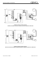
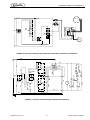
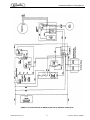


![WCC-700 Service Manual [ 058047 ]](http://vs1.manualzilla.com/store/data/006032662_1-9beff2067bf07b85dc4c0d9ee1d42eb7-150x150.png)
