1
1
2
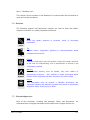
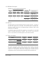
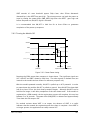
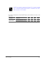
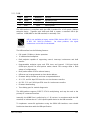
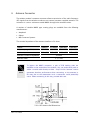
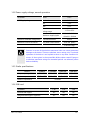
- These signals are required if the external SIM interface is used
- These pin connections are required for sleep mode operation
3, 4
- At least one of these interfaces is required to be connected
NOTE
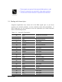
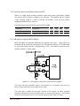
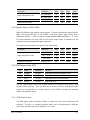
5.2 Dealing with Unused pins
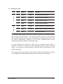
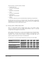
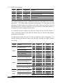
Integrators applications may connect all of the GR64 signals pins, or just those
necessary for minimal operation, or most commonly some other permutation.
If
GR64 signal pins are not connected to the host application you should terminate
them in the following manner.
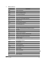
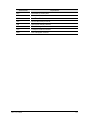
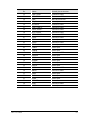
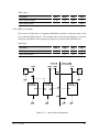
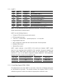
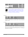
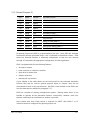
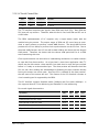
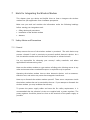
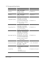
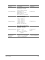
Table 5.2-1 Unused Pin Termination
Pin
Name
Unused pin termination
1, 3, 5, 7, 9
VCC
Must be connected
2, 4, 6, 8, 10, 12
GND
Must be connected
11
CHG_IN
Leave Open
13
ADIN4/GPIO5
Ground
14
ON/OFF
Must be connected
15
SIMVCC
Leave Open
16
SIMDET
Leave Open
17
SIMRST
Leave Open
18
SIMDAT
Leave Open
19
SIMCLK
Leave Open
20
DAC
Leave Open
21
GPIO1
Connect to VREF
22
GPIO2
Connect to VREF
23
GPIO3
Connect to VREF
24
GPIO4
Connect to VREF
25
VRTC
Leave Open
26
ADIN1
Ground
27
ADIN2
Ground
28
ADIN3
Ground
29
SDA
Leave Open
30
SCL
Leave Open
31
BUZZER
Leave Open
LZT 123 1834
32