1
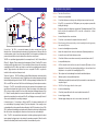
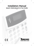
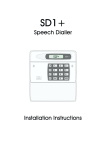
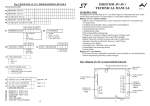
10. Specifications
Power input:
11.5V - 14V
Current consumption:
35mA (standby); 70mA (Active)
Trigger inputs:
A, B, C (+ve or -ve applied, input voltage 5 - 28V)
Phrases A,B,C,0:
40 seconds ± 2 seconds, sampled at 8KHz
Telephone Numbers:
4 x 24 digit telephone numbers
Case dimensions:
130(L) x 130(H) x 30(D) mm
REN value:
0
BT approvals:
S/1100/3/P/502920
Unit designed to
BS6301: 1989, BS6305: 1982, BS6789 and BS60950
SD1+
Speech Dialler
SD1+
Menvier Security Ltd.
Kenn Road, Clevedon, Bristol BS21 6LH
Tel: 01275 870078; Fax: 01275 343453
MENVIER
SECURITY
SD1 +
1
2
3
4
5
6
7
8
9
ENT
0
ESC
A
B
C
Email: [email protected]
Internet: http//:www.menviersecurity.co.uk
Installation Instructions
18037
Drg No. 33:2039:00 Iss 02. Doc 01 February, 1998
7. BT. Connections
2. Installation Requirements
1.
Remove the centre PCB screw and remove the plastic cover over the telephone
connection terminals.
2.
Connect telephone line using one of the methods shown below:
The SD1+ has been designed to be connected to an intruder alarm control panel or
similar. The control panel must have an auxiliary power output of between 11.5V and 14V,
and the ability to provide a minimum of 100mA.
3.
Replace the plastic cover over the telephone line connections.
+
The unit is supplied with a 2 metre telephone lead which will plug directly into any standard
BT socket and it is therefore recommended that the unit is sited as near to a BT telephone
socket as possible. If this it not possible an approved BT extension lead may be required or
the unit can be hard wired to the BT. socket (see section 8).
Failure to refit the plastic cover will contravene mandatory European standards
Method 1 - Using the lead supplied
3. Mounting Instructions
SD1+
White
Red
A
B
Standard BT telephone plug
1.
Separate the cover from the base by using a screwdriver to push two of the retaining
clips (top or bottom) inwards from the base indents. Remove cover assembly and
store in a safe place.
2.
Hold the base in position (keyhole to the top) and mark the three securing holes.
Remove the base then drill and plug the holes.
3.
Pass all cables into the base through the cable entries and then secure the base to
wall.
4. PCB Layout
Method 2 - Hard wired connections
BT Master Jack (NTE5)
User accessible connections
Cable type 1/0.5mm CW1308
3
2
1
Blue/White
Trigger Polarity
Jumper-link
A
B
12V Power Input
8. Commissioning and Testing
1.
2.
Hold the blade of a small screwdriver between the “Factory Restart” pins (JP2) and
switch the power back on to the control panel (battery and mains).
Remove the screwdriver blade and clip the SD1+ front cover onto the base taking
care not to trap any cables.
3.
The SD1+ "beeps" every 30 seconds and the display shows: PLEASE RECORD.
4.
To select the programming mode enter the default passcode of [1] [2] [3] [4].
5.
The display will show READY. The unit is now ready for programming and testing. Please
refer to the ”Operating Instructions” for full details.
(SELV)
Output 1
Abort Input
+
Factory Restart
SD1+
TRIG
POLARITY
MENVIER
SD1+
Factory
Restart
Pins
SECURITY
+12v
0v
O/P1
Microphone
ABORT
TRIG A
3 Trigger Inputs
TRIG B
Plastic cover
TRIG C
Box Tamper
TAMP
White/Blue
6
5
4
Tamper switch
A B
TELEPHONE CONNECTIONS
Loudspeaker
Telephone Line
Connection
Terminals
(TNV)
1. Overview
9. Troubleshooting Guide
Tel No 1
B
C
A
Problem
The unit will not dial out.
Cause
Number incorrectly dialled
Action
Check the telephone number you are calling has been entered correctly.
Cause
If the SD1+ is connected to a PABX system you may require a pause after
dialling the first digit.
Action
Program a pause in the telephone number (see “Operating Instructions”). If this
does not solve the problem the SD1+ must be connected to a direct
telephone line.
Cause
Incorrect telephone line connections.
Action
Check the connections to the telephone line (see section 7).
Problem
When the unit calls the recipient they can't acknowledge the unit by pressing
the number [8] button.
Cause
Incorrect acknowledgement procedure.
Action
Instruct the recipient in the correct procedure (see Operating Instructions).
Cause
Incorrectly connected to the telephone socket.
Action
Check that all three connections are correctly connected (see section 7).
Cause
Incompatible telephone.
Action
Call the recipient and ask them to press the number [8] button on their
telephone for 1 second. If you hear anything other than a 1 second tone, their
telephone is not capable of acknowledging the SD1+.
Problem
The recipient can't acknowledge the unit with a mobile telephone.
Cause
Weak reception or incompatible telephone.
Action
Mobile telephones will only work correctly if they are used in an area where the
reception is good.
Problem
The SD1+ will not trigger from the alarm panel.
Cause
Incorrect polarity setting.
Action
Check the jumper-link is set to the correct position (see section 5).
Cause
Incorrect trigger voltage.
Action
Measure trigger voltage and check connections ( see section 6).
Telephone
Tel No 2
1
2
3
4
5
6
7
8
9
Tel No 3
0
Speech Dialler
BT Line
Control Panel
Tel No 4
Connections: The SD1+ is connected between the alarm control panel and the
telephone line. It behaves like another extension to the telephone and does not affect its
normal operation or that of any other extension fitted. The unit requires no batteries as its
power and mains fail back-up are derived from the alarm control panel.
The SD1+ accepts three trigger inputs which in our example are; A - Fire, B - Personal Attack
(PA) and C - Burglary. These correspond to the messages (A, B and C) that the SD1+ sends
out and should be recorded as such. If the control panel does not have a fire monitoring
capability then the SD1+ will accept a direct connection from a suitable smoke alarm (as
above). Trigger inputs can be selected as +ve or -ve applied. The SD1+ may also be
included in the control panel tamper circuit.
Telephone Numbers: The SD1+ will dial up to four different telephone numbers and play
its message. The numbers may be up to 24 digits long and are simply programmed using
the text display and keypad on the unit. The SD1+ also supports pager numbers. Note: The
SD1+ must NOT be used to call the Police via the Emergency Services phone numbers.
Messages: The SD1+ has a built-in microphone and speaker so that messages can be
recorded and replayed directly from the unit. When the outgoing call is answered the
SD1+ plays a common phrase (0) and one of the three alarm messages (phrases A, B or
C). Phrase 0 normally states the name and address of the site and phrases A, B and C
relate to the inputs from the control panel (Fire, PA, and Burglary in our example). A total of
40 seconds is available for recording messages.
Acknowledgement: On receiving a call from the SD1+ the person answering the call
can acknowledge it by pressing number [8] on their telephone. If the message is not
acknowledged then it is repeated four times after which the SD1+ abandons the call. The
SD1+ has several acknowledgement options which allows the unit to stop dialling after the
first call has been acknowledged or when two or three have been acknowledged.
Abort: The SD1+ has several abort options which include applying a signal to the abort
input, restoring the trigger input or by entering the operators passcode. When the unit is
aborted it immediately shuts down and returns to its normal standby mode.
5. SD1+ Connections
6. Control Panel Connections
Before any connections are made to the SD1+ remove the power (battery and 240V
mains) from the control panel. Connections are provided as follows:
The table below shows the connection details to various control panels.
Control Panel
TRIG A
Fire
TRIG B
PA
TRIG C
Alarm
Polarity
Supply +
Supply -
Trigger
Type
When triggered, the unit starts the dialling sequence and sends
message A.
Menvier TS400/TS410
Zone 4
Zone 5
ALM
-
Aux +
Aux -
0V app.
When triggered, the unit starts the dialling sequence and sends
message B.
N/A
OP 2 *
OP 1 *
-
Aux +
Aux -
0V app.
Menvier TS690R
OP 1
OP 2
OP 3
-
Aux +
Aux -
0V app.
Menvier TS690/TS700
Digi 1
Digi 2
Digi 3
-
Aux +
Aux -
0V app.
Menvier TS790/TS900/TS2500
ABORT:
When triggered, the SD1+will abort the dialling sequence.
TRIG A:
TRIG B:
TRIG C:
When triggered, the unit starts the dialling sequence and sends
message C.
Trigger/Abort inputs can be selected to be either +ve applied to
trigger or -ve applied to trigger. Set the "Trigger Polarity" jumper-link to
the appropriate position. The figure below shows the different types of
output types that can be connected to the SD1+.
BOX TAMPER:
0V:
These two terminals can be connected to the main tamper zone on
the alarm control panel, to provide case tamper protection for the
SD1+.
Menvier TS510
Digi 1
Digi 2
Digi 3
-
Aux+
Aux -
0V app.
A1 Advantage
N/A
N/A
Bell -
-
Aux +
Aux -
0V app.
ADE Optima XM
N/A
N/A
B
-
13V +
13V -
0V app.
ADE Optima 2+
Fire
PA
Intruder
-
13V +
13V -
0V app.
ADE Concept 6
N/A
N/A
B
-
13V +
13V -
0V app.
ADE Accenta 6
N/A
N/A
B
-
13V +
13V -
0V app.
Ademco Infra 6
N/A
N/A
3
+
Aux +
Aux -
12V app.
Connect to a permanent 0V supply on the control panel.
Ademco Infra 16
1*
2
3
+
Aux +
Aux -
12V app.
+12V:
Connect to a permanent +12V supply on the control panel.
C & K 700L
N/A
N/A
S-
-
Aux +
Aux -
0V app.
O/P1:
A switched -ve programmable output.
CQR Premia 9
FA *
PA
IA
+
Aux 12V
Aux 0V
12V app.
DA Abacus 6
N/A
N/A
Bell
-
+12V
0V
0V app.
DA Abacus 8
N/A
N/A
Bell
-
+12V
0V
0V app.
Gardtec 500 Series
N/A
N/A
Bell -
-
Power +
Power -
0V app.
Gardtec 800 Series
D1 *
PA
12Hr
-
12V
0V
0V app.
TRIG POLARITY
+
TRIG POLARITY
+
+12V
0V
N.C.
Loop
SD1
TRIG A
TRIG B
TRIG C
TRIG A = Normally Closed Input
TRIG B = Normally Open Input
TRIG C = Switched +ve Input
+
+
1K
resistor
N.O.
Loop
12V on alarm
+12V
0V
JSB Regent
N.O.
Loop
SD1
TRIG A
TRIG B
TRIG C
1K
resistor
N.C.
Loop
0V on alarm
TRIG A = Normally Open Input
TRIG B = Normally Closed Input
TRIG C = Switched -ve Input
Connections on the SD1+ are described as ether "Safety Extra-Low Voltage" circuits (SELV) or
"Telecommunication Network Voltages" circuits (TNV). Therefore it is important that installer
ensures that TNV circuits are only connected to the PSTN and SELV circuits are only
connected to other circuits designated as SELV circuits.
Please ensure that cabling to the telephone line connections (TNV) are routed well away
from the trigger input circuitry (SELV) and the cabling to the trigger input circuitry (SELV) are
routed well away from the telephone circuitry (TNV).
COM1
COM2
COM3
+
12V
0V
12V app.
Pyronix Paragon + /E
N/A
N/A
BA
-
Aux +
Aux -
0V app.
Pyronix Octagon
N/A
PA
ALM
-
Aux +
Aux -
0V app.
Pyronix Conqueror
N/A
N/A
BA
-
Aux +
Aux -
0V app.
Scantronic 9448
N/A
COM 2
COM 3
-
12V
0V
5V rem.
Scantronic 9452/3
N/A
COM 1
COM 3
-
Aux 12V
Aux 0V
5V rem.
Scantronic 9454
N/A
COM 1
COM 3
-
12V
0V
5V rem.
Scantronic 9455
N/A
COM 1
COM 3
-
12V
0V
5V rem.
Texecom Veritas R8
N/A
N/A
B
-
Aux +
Aux -
0V app.
Texecom Veritas 8 Compact
N/A
N/A
B
-
Aux +
Aux -
0V app.
* Control panel output requires programming.
+
When using the bell output to trigger the SD1+, you may find that the external sounder is
partially triggered. If this is the case a 1K resistor will need to be connected between the
SD1+ trigger input and +12V.