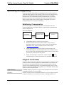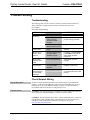
1
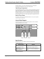
Crestron C2N-FTB-D FlipTop Control Center, Dual AC Outlets Operations & Installation Guide This document was prepared and written by the Technical Documentation department at: Crestron Electronics, Inc. 15 Volvo Drive Rockleigh, NJ 07647 1-888-CRESTRON All brand names, product names and trademarks are the property of their respective owners. ©2008 Crestron Electronics, Inc. Crestron C2N-FTB-D FlipTop Control Center, Dual AC Outlets Contents FlipTop Control Center, Dual AC Outlets: C2N-FTB-D 1 Introduction ............................................................................................................................... 1 Features and Functions ................................................................................................ 1 Internal Block Diagram ............................................................................................... 2 Specifications .............................................................................................................. 2 Physical Description.................................................................................................... 4 Industry Compliance ................................................................................................... 8 Setup .......................................................................................................................................... 9 Network Wiring........................................................................................................... 9 Identity Code ............................................................................................................... 9 Installation ................................................................................................................... 9 Hardware Hookup ..................................................................................................... 15 Programming Software ............................................................................................................ 17 Earliest Version Software Requirements for the PC ................................................. 17 Programming with Crestron SystemBuilder.............................................................. 17 Programming with SIMPL Windows ........................................................................ 17 Example Program ...................................................................................................... 19 Uploading and Upgrading........................................................................................................ 20 Establishing Communication..................................................................................... 20 Programs and Firmware ............................................................................................ 20 Program Checks ........................................................................................................ 21 Problem Solving ...................................................................................................................... 22 Troubleshooting......................................................................................................... 22 Check Network Wiring.............................................................................................. 22 Reference Documents................................................................................................ 22 Further Inquiries ........................................................................................................ 22 Future Updates .......................................................................................................... 24 Return and Warranty Policies .................................................................................................. 25 Merchandise Returns / Repair Service ...................................................................... 25 CRESTRON Limited Warranty................................................................................. 25 Operations & Installation Guide – DOC. 6639B Contents • i Crestron C2N-FTB-D FlipTop Control Center, Dual AC Outlets FlipTop Control Center, Dual AC Outlets: C2N-FTB-D Introduction Features and Functions The C2N-FTB-D provides an ingenious control and connectivity solution in a stylish flush mount tabletop package. Simply flip open the “FlipTop” lid to expose a pushbutton keypad, perfectly angled for easy access and operation. The built-in cable storage compartment keeps interface cables at the ready for plugging in computers, AV sources and a host of other devices. The C2N-FTB-D is available in two models, the C2N-FTB-D-B, which has a black anodized finish and the C2N-FTB-D-BALUM, which has a brushed aluminum finish. For simplicity within this guide, the suffix is omitted and C2N-FTB-D is used except where noted. • • • • • • • Stylish flush mount FlipTop housing Integrated keypad with dual bar graphs Easy pull-out universal cable management (2) AC power outlets Cresnet® communications Built-in engravable* keypad with 10 to 20 buttons and LEDs Cable support plate included * As an option, custom engraved buttons can be designed and obtained by using Crestron Engraver software. They are available from the Crestron® website (at www.crestron.com). FlipTop Housing Handsomely finished in either black anodized or brushed aluminum, the C2N-FTB-D mounts flush in any tabletop surface for a clean, discreet appearance. Integrated Keypad The customizable keypad provides 10 to 20 programmable pushbuttons for control of AV, lighting and other functions. All button caps are engravable and include LED feedback indicators. Two LED bar graphs are also provided to display level settings Operations & Installation Guide – DOC. 6639B FlipTop Control Center, Dual AC Outlets: C2N-FTB-D • 1 FlipTop Control Center, Dual AC Outlets Crestron C2N-FTB-D and other parameters. To prevent accidental button presses, the keypad is automatically disabled whenever the lid is not fully opened. Cable Storage Compartment The C2N-FTB-D also provides for extensive connectivity through an easy pull-out cable storage mechanism to support a wide range of applications and signal types. Eight grommeted holes are provided in the bottom plate, allowing for smooth pass through of virtually any type of AV, communication, control or data cable (cables not included). When not in use, the user end of each cable stows neatly within the FlipTop compartment while excess cable simply drops out of sight below the box. Dual AC Power Outlets For complete connectivity, the C2N-FTB-D includes two AC power receptacles within the FlipTop compartment. Internal Block Diagram The following diagram represents the interfacing abilities of the C2N-FTB-D. Internal Block Diagram of the C2N-FTB-D AC Outlet AC Outlet AC Power Cresnet Cresnet Keypad Specifications Specifications for the C2N-FTB-D are listed in the following table. C2N-FTB-D Specifications SPECIFICATION DETAILS Power Cresnet Power Usage 2 Watts (0.083 Amp @ 24 Volts DC) Default Net ID 1E Minimum 2-Series Control System Update File1, 2 Version 3.125.CUZ (for QM-RMCRX) or later (Continued on follow page) 2 • FlipTop Control Center, Dual AC Outlets: C2N-FTB-D Operations & Installation Guide – DOC. 6639B Crestron C2N-FTB-D FlipTop Control Center, Dual AC Outlets C2N-FTB-D Specifications (Continued) SPECIFICATION DETAILS Black painted metal with black anodized or brushed aluminum cover; flush tabletop mountable Enclosure Environmental Temperature 41º to 104ºF (5º to 40ºC) Humidity 10% to 90% RH (non-condensing) Heat Dissipation 6 BTU/Hr Dimensions Height 5.39 in (13.69 cm) with lid closed Width 6.75 in (17.14 cm) Depth 5.71 in (14.50 cm) Weight 3.75 lbs (1.70 kg) Available Models C2N-FTB-B FlipTop Control Center, Dual AC Outlets, Black Anodized C2N-FTB-BALUM FlipTop Control Center, Dual AC Outlets, Brushed Aluminum Available Accessories FT-BTNB-L (1) Large engravable button cap FT-BTNB-L-BLANK (1) Large button cap, not engraved FT-BTNB-S (2) Small engravable button caps FT-BTNB-S-BLANK (2) Small button caps, not engraved 1. The latest software versions can be obtained from the Crestron website. Refer to the NOTE following these footnotes. 2. Crestron 2-Series control systems include the AV2 and PRO2. Consult the latest Crestron Product Catalog for a complete list of 2-Series control systems. NOTE: Crestron software and any files on the website are for authorized Crestron dealers and Crestron Authorized Independent Programmers (CAIP) only. New users may be required to register to obtain access to certain areas of the site (including the FTP site). Operations & Installation Guide – DOC. 6639B FlipTop Control Center, Dual AC Outlets: C2N-FTB-D • 3 FlipTop Control Center, Dual AC Outlets Crestron C2N-FTB-D Physical Description This section provides information on the connections, controls and indicators available on your C2N-FTB-D. C2N-FTB-D Physical View C2N-FTB-D Overall Dimensions (Top View) 6.75 in (17.14 cm) 5.08 in (12.89 cm) 5.71 in (14.50 cm) 4 • FlipTop Control Center, Dual AC Outlets: C2N-FTB-D Operations & Installation Guide – DOC. 6639B Crestron C2N-FTB-D FlipTop Control Center, Dual AC Outlets C2N-FTB-D Overall Dimensions (Front View) C2N-FTB-D Overall Dimensions (Bottom View) 5.16 in (13.10 cm) 6.25 in (15.87 cm) C2N-FTB-D Overall Dimensions (Rear View) C2N-FTB-D Overall Dimensions (Side View) 2.32 in (5.88 cm) 4.32 in (10.96 cm) 5.39 in (13.69 cm) 4.58 in (11.63 cm) 5.21 in (13.23 cm) Operations & Installation Guide – DOC. 6639B FlipTop Control Center, Dual AC Outlets: C2N-FTB-D • 5 FlipTop Control Center, Dual AC Outlets Crestron C2N-FTB-D C2N-FTB-D Connectors, Controls & Indicators (Top View) 1 2 4 3 5 C2N-FTB-D Connectors, Controls & Indicators (Bottom View) 6 6 • FlipTop Control Center, Dual AC Outlets: C2N-FTB-D 7 8 9 Operations & Installation Guide – DOC. 6639B Crestron C2N-FTB-D FlipTop Control Center, Dual AC Outlets Connectors, Controls & Indicators * # CONNECTORS*, CONTROLS & INDICATORS DESCRIPTION 1 KEYPAD Programmable keypad allowing variable combinations of large and small engravable buttons, 10 minimum (all large) to 20 maximum (all small); ships with 10 large buttons (small buttons and engraving sold separately) (1) red LED per button, programmable. 2 PWR (1) Green LED, indicates 24 Volts DC power supplied from Cresnet control network. 3 NET (1) Yellow LED, indicates communication with Cresnet system. 4 BAR GRAPHS 5 125V (2) Grounded AC sockets, AC power pass through outlets; Maximum load: 10 Amps (total) @ 120 Volts AC, 50/60 Hz 6 125V (1) 9 foot grounded AC line cord; passes through to front panel AC power outlets. 7 NET (2) Four-position terminal block connectors for data and power. Connect to Cresnet control network. Pin 1 (24) Power (24 Volts DC) Pin 2 (Y) Data Pin 3 (Z) Data Pin 4 (G) Ground 8 SETUP (1) Miniature pushbutton and red LED, used for touch-settable ID (TSID) Used for setting network ID during initial configuration or when the device is being added/replaced. 9 G (2) Red 8-segment LED bar graphs, programmable. (1) 6-32 screw, chassis ground lug. Interface connectors for NET ports are provided with the unit. Operations & Installation Guide – DOC. 6639B FlipTop Control Center, Dual AC Outlets: C2N-FTB-D • 7 FlipTop Control Center, Dual AC Outlets Crestron C2N-FTB-D Industry Compliance As of the date of manufacture, the C2N-FTB-D has been tested and found to comply with specifications for CE marking and standards per EMC and Radiocommunications Compliance Labelling. NOTE: This device complies with part 15 of the FCC rules. Operation is subject to the following two conditions: (1) this device may not cause harmful interference and (2) this device must accept any interference received, including interference that may cause undesired operation. This equipment has been tested and found to comply with the limits for a Class B digital device, pursuant to part 15 of the FCC Rules. These limits are designed to provide reasonable protection against harmful interference in a residential installation. This equipment generates, uses and can radiate radio frequency energy and if not installed and used in accordance with the instructions, may cause harmful interference to radio communications. However, there is no guarantee that interference will not occur in a particular installation. If this equipment does cause harmful interference to radio or television reception, which can be determined by turning the equipment off and on, the user is encouraged to try to correct the interference by one or more of the following measures: Reorient or relocate the receiving antenna. Increase the separation between the equipment and receiver. Connect the equipment into an outlet on a circuit different from that to which the receiver is connected. Consult the dealer or an experienced radio/TV technician for help. 8 • FlipTop Control Center, Dual AC Outlets: C2N-FTB-D Operations & Installation Guide – DOC. 6639B Crestron C2N-FTB-D FlipTop Control Center, Dual AC Outlets Setup Network Wiring When wiring the Cresnet® network, consider the following: • Use Crestron Certified Wire. • Use Crestron power supplies for Crestron equipment. • Provide sufficient power to the system. CAUTION: Insufficient power can lead to unpredictable results or damage to the equipment. Please use the Crestron Power Calculator to help calculate how much power is needed for the system (www.crestron.com/calculators). • For larger networks, use a Cresnet Hub/Repeater (CNXHUB) to maintain signal quality. For more details, refer to “Check Network Wiring” on page 22. Identity Code The Net ID of the C2N-FTB-D has been factory set to 1E. The Net IDs of multiple C2N-FTB-D devices in the same system must be unique. Net IDs are changed from a personal computer (PC) via the Crestron Toolbox™ (refer to “Establishing Communication” on page 20). When setting the Net ID, consider the following: • The Net ID of each unit must match an ID code specified in the SIMPL™ Windows® program. • Each network device must have a unique Net ID. For more details, refer to the Crestron Toolbox help file. Installation NOTE: To prevent overheating, do not operate this product in an area that exceeds the environmental temperature range listed in the table of specifications. Consideration must be given if installed in a closed or multi-unit rack assembly, inside a closed desk or in a closed podium since the operating ambient temperature of the environment may be greater than the room ambient temperature. Contact with thermal insulating materials should be avoided on all sides of the unit. Operations & Installation Guide – DOC. 6639B FlipTop Control Center, Dual AC Outlets: C2N-FTB-D • 9 FlipTop Control Center, Dual AC Outlets Crestron C2N-FTB-D Button Installation The C2N-FTB-D is shipped with ten large blank buttons. You can order a variety of button kits (sold separately) for a total of 20 engraved or blank buttons. Button Kits KIT NUMBER DESCRIPTION FT-BTNB-L One large button engraved as desired FT-BTNB-L-BLANK One large button not engraved FT-BTNB-S Two small buttons with divider engraved as desired FT-BTNB-S-BLANK Two small buttons with divider, not engraved To replace the supplied large blank buttons with large engraved buttons or small buttons, follow this procedure. A 1/16" Allen (hexhead) wrench is required to remove the button faceplate. 1. Remove the four Allen screws that secure the button faceplate. 2. While holding adjacent buttons in place, carefully pull the button(s) to be replaced from the rubber membrane. 3. Carefully press the large replacement button or two small replacement buttons in place, making sure LED window faces up. Use care not to dislodge the membrane and circuit board. NOTE: The removable buttons fit snugly on the rubber membrane. Remove carefully to avoid pulling the membrane from the unit. 4. For small replacement buttons, the divider bar slips into the slots on the back of the faceplate. 5. Replace the faceplate using the four Allen screws. Button Installation 10 • FlipTop Control Center, Dual AC Outlets: C2N-FTB-D Operations & Installation Guide – DOC. 6639B Crestron C2N-FTB-D FlipTop Control Center, Dual AC Outlets Cable Support Plate The C2N-FTB-D is shipped with a cable support plate that provides an easy pullout cable solution for the computer input and LAN pass through cables. Parts Supplied for Cable Support DESCRIPTION PART NUMBER QUANTITY 2011563 1 Cable Bushing, 0.55” ID, 0.80” OD 2010496 2 Cable Bushing, 0.39” ID, 0.64” OD 2011070 2 Cable Support Plate Cable Bushing, 5/16“ ID, 0.5” OD 2009522 4 #4-40- x ¼”, Pan Head Phillips Screws 2007158 4 The cable support plate must be installed before mounting the C2N-FTB-D to a surface. The cables are looped through the plate. A Phillips screwdriver is required to install the plate. 1. Place the bushings on the cables (eight bushings supplied). 2. Thread the cables through the appropriate slot on the plate. 3. Snap the bushings into the plate slots. The bushings protect the cables from chafing against the metal edge of the plate. 4. Feed all the excess cable through the opening. 5. Use a Phillips screwdriver to attach the plate using the four #4-40 x ¼” black screws. 6. The cables may be secured to the bottom bar using tie wraps (not supplied). Plate Installation Operations & Installation Guide – DOC. 6639B FlipTop Control Center, Dual AC Outlets: C2N-FTB-D • 11 FlipTop Control Center, Dual AC Outlets Crestron C2N-FTB-D When selecting cables for installation in the C2N-FTB-D, cable connector length and strain relief diameter are important considerations. • If the connector is too long, it can interfere with cover operation and scratch the buttons. • If the width of the cable strain relief is too similar to the bushing inside diameter, the bushing can trap the cable. NOTE: Do not use the cable support plate without the bushings. Example Cable End Cable Passes Through the Plate NOTE: Ensure that the cables have sufficient clearance to enable smooth movement. Allow approximately 40 inches (102 cm) from the top surface of the FlipTop box. 12 • FlipTop Control Center, Dual AC Outlets: C2N-FTB-D Operations & Installation Guide – DOC. 6639B Crestron C2N-FTB-D FlipTop Control Center, Dual AC Outlets Mounting to Surface The C2N-FTB-D is designed to mount in a horizontal surface such as a desk top, lectern or podium. The following diagram illustrates the required opening size to accommodate the C2N-FTB-D. A cutout template (4010018) is included. Cutout Dimensions 6 3/8 in (162 mm) Maximum Radius 1/8 in (4 mm) 5 5/16 in (135 mm) Mounting Parts Supplied with the C2N-FTB-D DESCRIPTION PART NUMBER QUANTITY 2013224 2 #10-32 x 2” Pan Head, Phillips Screw 2007293 4 #6-32 x 3/16” Pan Head, Phillips Screw 2007204 4 Mounting Bracket A Phillips screwdriver is required to mount the C2N-FTB-D to a surface. NOTE: Before inserting the C2N-FTB-D in the mounting hole, ensure that all required cables have been installed. 1. Install the four supplied #6-32 screws on the front but do not tighten. Four are already installed on the rear. These will be used to secure the front and rear mounting brackets. 2. Position the C2N-FTB-D in the mounting hole. Operations & Installation Guide – DOC. 6639B FlipTop Control Center, Dual AC Outlets: C2N-FTB-D • 13 FlipTop Control Center, Dual AC Outlets Crestron C2N-FTB-D Mounting Bracket Screw Locations 3. Install the four #10 screws in the mounting brackets (two screws per bracket). Refer to the following diagram. 4. Slide the mounting brackets over the #6-32 screws and tighten all eight #6-32 screws. 5. Turn the four #10 screws equally until they contact the underside of the mounting surface. NOTE: Do not over-tighten the #10 screws as this may damage the surface and/or the unit. Mounting Bracket Installation 14 • FlipTop Control Center, Dual AC Outlets: C2N-FTB-D Operations & Installation Guide – DOC. 6639B Crestron C2N-FTB-D FlipTop Control Center, Dual AC Outlets NOTE: Be careful not to press the buttons while closing the FlipTop, even though the buttons are disabled when the FlipTop begins to close and all pressed buttons are released. Hardware Hookup Connect the Device Make the necessary connections as called out in the illustration that follows this paragraph. Refer to “Network Wiring” on page 9 before attaching the 4-position terminal block connector. Apply power after all connections have been made. When making connections to the C2N-FTB-D, consider the following: • Use Crestron power supplies for Crestron equipment. • The included cable cannot be extended. Underside Hardware Connections for the C2N-FTB-D GROUND 120 VAC LINE CORD NET: TO CONTROL SYSTEM AND OTHER CRESNET DEVICES Operations & Installation Guide – DOC. 6639B TSID SETUP BUTTON AND LED FlipTop Control Center, Dual AC Outlets: C2N-FTB-D • 15 FlipTop Control Center, Dual AC Outlets Crestron C2N-FTB-D NOTE: The maximum continuous current from equipment under any external load conditions shall not exceed a current limit that is suitable for the minimum wire gauge used in interconnecting cables. The ratings on the connecting unit's supply input should be considered to prevent overloading the wiring. NOTE: Ensure the unit is properly grounded. Ground Wire Connections Proper grounding is required. Connect the ground from the C2N-FTB-D to earth ground. Connect the Cresnet shield lead at the control processor to the ground lead. The control processor chassis must also be connected to an earth ground (building steel). Refer to the following grounding diagram. Ground Wire Connections Control Processor Ground Wire to Earth Ground Cresnet 24 Y Z G C2N-FTB-D Shield Ground Wire to Earth Ground NOTE: Do not connect the shield to earth ground at the C2N-FTB-D. 16 • FlipTop Control Center, Dual AC Outlets: C2N-FTB-D Operations & Installation Guide – DOC. 6639B Crestron C2N-FTB-D FlipTop Control Center, Dual AC Outlets Programming Software Have a question or comment about Crestron software? Answers to frequently asked questions (FAQs) can be viewed in the Online Help section of the Crestron website. To post a question or view questions you have submitted to Crestron’s True Blue Support, log in at http://support.crestron.com. First-time users will need to establish a user account. Earliest Version Software Requirements for the PC NOTE: Crestron recommends that you use the latest software to take advantage of the most recently released features. The latest software is available from the Crestron website. Crestron has developed an assortment of Windows-based software tools to develop a Cresnet system. For the minimum recommended software versions, visit the Version Tracker page of the Crestron website (www.crestron.com/versiontracker). Programming with Crestron SystemBuilder Crestron SystemBuilder is the easiest method of programming but does not offer as much flexibility as SIMPL Windows. For additional details, download SystemBuilder from the Crestron website and examine the extensive help file. Programming with SIMPL Windows NOTE: While SIMPL Windows can be used to program the C2N-FTB-D, it is recommended to use SystemBuilder for configuring a system. SIMPL Windows is Crestron’s premier software for programming Crestron control systems. It is organized into two separate but equally important “Managers”. Configuration Manager Configuration Manager is the view where programmers “build” a Crestron control system by selecting hardware from the Device Library. • To incorporate the C2N-FTB-D into the system, drag the C2N-FTB from the Wired Keypads folder of the Device Library and drop it in the System Views. Operations & Installation Guide – DOC. 6639B FlipTop Control Center, Dual AC Outlets: C2N-FTB-D • 17 FlipTop Control Center, Dual AC Outlets Crestron C2N-FTB-D Locating the C2N-FTB in the Device Library • The system tree of the control system displays the device in the appropriate slot with a default Net ID as shown in the following illustration. C2Net Device, Slot 9 • Additional C2N-FTB-D devices (shown as C2N-FTB) are assigned different Net ID numbers as they are added. • If necessary, double click a device to open the “Device Settings” window and change the Net ID, as shown in the following figure. 18 • FlipTop Control Center, Dual AC Outlets: C2N-FTB-D Operations & Installation Guide – DOC. 6639B Crestron C2N-FTB-D FlipTop Control Center, Dual AC Outlets “C2N-FTB Device Settings” Window • Program Manager The ID code specified in the SIMPL Windows program must match the Net ID of each unit. Refer to “Identity Code” on page 9. Program Manager is the view where programmers “program” a Crestron control system by assigning signals to symbols. The symbol can be viewed by double clicking on the icon or dragging it into Detail View. Each signal in the symbol is described in the SIMPL Windows help file (F1). The button presses are fixed and map to <press> outputs on the symbol detail as follows: Row 1 Row 2 1 2 3 4 5 6 7 8 9 10 Row 3 Row 4 11 12 13 14 15 16 17 18 19 20 PWR NET NOTE: Numbers in this illustration are for programming purposes only. The buttons on rows 1 and 2 can be combined vertically to form one larger button. For example, the button caps for buttons #1 and #6 can be replaced with one larger button cap. Similarly, the vertical pairs on rows 3 and 4 can be combined to form one larger button. For example, buttons #13 and #18 can be combined. No other combinations are valid. That is, two buttons cannot be combined horizontally; the buttons on rows 2 and 3 cannot be combined. Example Program An example program for the C2N-FTB-D is available from the Crestron website (www.crestron.com/exampleprograms). Operations & Installation Guide – DOC. 6639B FlipTop Control Center, Dual AC Outlets: C2N-FTB-D • 19 FlipTop Control Center, Dual AC Outlets Crestron C2N-FTB-D Uploading and Upgrading Crestron recommends using the latest programming software and that each device contains the latest firmware to take advantage of the most recently released features. However, before attempting to upload or upgrade it is necessary to establish communication. Once communication has been established, files (for example, programs or firmware) can be transferred to the control system (and/or device). Finally, program checks can be performed (such as changing the device ID or creating an IP table) to ensure proper functioning. Establishing Communication Use Crestron Toolbox for communicating with the C2N-FTB-D; refer to the Crestron Toolbox help file for details. There is a single method of communication: indirect communication. Indirect Communication PC RUNNING CRESTRON TOOLBOX CONTROL SYSTEM SERIAL, ETHERNET OR USB C2N-FTB-D CRESNET • C2N-FTB-D connects to control system via Cresnet. • Establish communication between the PC and the control system as described in the latest version of the 2-Series Control Systems Reference Guide (Doc. 6256), which is available from the Crestron website (www.crestron.com/manuals). • Use the Address Book in Crestron Toolbox to create an entry for the C2N-FTB-D using the expected communication protocol (Indirect). Select the Cresnet ID of the C2N-FTB-D and the address book entry of the control system that is connected to the C2N-FTB-D. • icon); Display the C2N-FTB-D’s “System Info” window (click the communications are confirmed when the device information is displayed. Programs and Firmware Program or firmware files may be distributed from programmers to installers or from Crestron to dealers. Firmware upgrades are available from the Crestron website as new features are developed after product releases. One has the option to upload programs via the programming software or to upload and upgrade via the Crestron Toolbox. For details on uploading and upgrading, refer to the SIMPL Windows help file or the Crestron Toolbox help file. SIMPL Windows If a SIMPL Windows program is provided, it can be uploaded to the control system using SIMPL Windows or Crestron Toolbox. Firmware Check the Crestron website to find the latest firmware. (New users may be required to register to obtain access to certain areas of the site, including the FTP site.) 20 • FlipTop Control Center, Dual AC Outlets: C2N-FTB-D Operations & Installation Guide – DOC. 6639B Crestron C2N-FTB-D FlipTop Control Center, Dual AC Outlets Upgrade C2N-FTB-D firmware via Crestron Toolbox. • Establish communication with the C2N-FTB-D and display the “System Info” window. • Select Functions | Firmware… to upgrade the C2N-FTB-D firmware. Program Checks Using Crestron Toolbox, display the network device tree (Tools | Network Device Tree) to show all network devices connected to the control system. Right-click on the C2N-FTB-D to display actions that can be performed on the C2N-FTB-D. Operations & Installation Guide – DOC. 6639B FlipTop Control Center, Dual AC Outlets: C2N-FTB-D • 21 FlipTop Control Center, Dual AC Outlets Crestron C2N-FTB-D Problem Solving Troubleshooting The following table provides corrective action for possible trouble situations. If further assistance is required, please contact a Crestron customer service representative. C2N-FTB-D Troubleshooting TROUBLE C2N-FTB-D is not functioning. POSSIBLE CAUSE(S) CORRECTIVE ACTION Net ID is incorrect. Verify the Net ID in Toolbox. Net ID is not set to match the Net ID specified in SIMPL Windows. Verify SIMPL Windows program setting for Net ID. Net ID is the same as another device’s Net ID. Assign a different Net ID. PWR LED does not illuminate. Device is not receiving power. Verify that Cresnet is properly attached. Buttons do not function when pressed. Net ID incorrect or does not match SIMPL Windows program. In Toolbox, check Functions | CresnetID to verify Net ID. Verify SIMPL Windows program ID. Button press yields incorrect result. Incorrect programming. Verify SIMPL Windows program. Button LED does not illuminate. Feedback signal names incorrect in SIMPL Windows. Verify SIMPL Windows feedback signal names. Loss of functionality due to electrostatic discharge. Improper grounding. Check that all ground connections have been made properly. Check Network Wiring Use the Right Wire In order to ensure optimum performance over the full range of your installation topology, Crestron Certified Wire and only Crestron Certified Wire may be used. Failure to do so may incur additional charges if support is required to identify performance deficiencies because of using improper wire. Calculate Power CAUTION: Use only Crestron power supplies for Crestron equipment. Failure to do so could cause equipment damage or void the Crestron warranty. CAUTION: Provide sufficient power to the system. Insufficient power can lead to unpredictable results or damage to the equipment. Please use the Crestron Power Calculator to help calculate how much power is needed for the system (www.crestron.com/calculators). 22 • FlipTop Control Center, Dual AC Outlets: C2N-FTB-D Operations & Installation Guide – DOC. 6639B Crestron C2N-FTB-D FlipTop Control Center, Dual AC Outlets When calculating the length of wire for a particular Cresnet run, the wire gauge and the Cresnet power usage of each network unit to be connected must be taken into consideration. Use Crestron Certified Wire only. If Cresnet units are to be daisychained on the run, the Cresnet power usage of each network unit to be daisychained must be added together to determine the Cresnet power usage of the entire chain. If the unit is home-run from a Crestron system power supply network port, the Cresnet power usage of that unit is the Cresnet power usage of the entire run. The wire gauge and the Cresnet power usage of the run should be used in the following equation to calculate the cable length value on the equation’s left side. Cable Length Equation 40,000 L< RxP Where: L = Length of run (or chain) in feet R = 6 Ohms (Crestron Certified Wire: 18 AWG (0.75 MM 2 )) or 1.6 Ohms (Cresnet HP: 12 AWG (4 MM 2 )) P = Cresnet power usage of entire run (or chain) Make sure the cable length value is less than the value calculated on the right side of the equation. For example, a Cresnet run using 18 AWG Crestron Certified Wire and drawing 20 watts should not have a length of run more than 333 feet. If Cresnet HP is used for the same run, its length could extend to 1250 feet. NOTE: All Crestron certified Cresnet wiring must consist of two twisted pairs. One twisted pair is the +24V conductor and the GND conductor and the other twisted pair is the Y conductor and the Z conductor. Strip and Tin Wire When daisy-chaining Cresnet units, strip the ends of the wires carefully to avoid nicking the conductors. Twist together the ends of the wires that share a pin on the network connector and tin the twisted connection. Apply solder only to the ends of the twisted wires. Avoid tinning too far up the wires or the end becomes brittle. Insert the tinned connection into the Cresnet connector and tighten the retaining screw. Repeat the procedure for the other three conductors. Add Hubs For larger networks (i.e., greater than 28 network devices), it may become necessary to add a Cresnet Hub/Repeater (CNXHUB) to maintain signal quality throughout the network. Also, for networks with lengthy cable runs it may be necessary to add a Hub/Repeater after only 20 devices. Reference Documents The latest version of all documents mentioned within the guide can be obtained from the Crestron website (www.crestron.com/manuals). This link will provide a list of product manuals arranged in alphabetical order by model number. List of Related Reference Documents DOCUMENT TITLE 2-Series Control Systems Reference Guide Further Inquiries If you cannot locate specific information or have questions after reviewing this guide, please take advantage of Crestron's award winning customer service team by calling Crestron at 1-888-CRESTRON [1-888-273-7876]. Operations & Installation Guide – DOC. 6639B FlipTop Control Center, Dual AC Outlets: C2N-FTB-D • 23 FlipTop Control Center, Dual AC Outlets Crestron C2N-FTB-D You can also log onto the online help section of the Crestron website (www.crestron.com/onlinehelp) to ask questions about Crestron products. First-time users will need to establish a user account to fully benefit from all available features. Future Updates As Crestron improves functions, adds new features and extends the capabilities of the C2N-FTB-D, additional information may be made available as manual updates. These updates are solely electronic and serve as intermediary supplements prior to the release of a complete technical documentation revision. Check the Crestron website periodically for manual update availability and its relevance. Updates are identified as an “Addendum” in the Download column. 24 • FlipTop Control Center, Dual AC Outlets: C2N-FTB-D Operations & Installation Guide – DOC. 6639B Crestron C2N-FTB-D FlipTop Control Center, Dual AC Outlets Return and Warranty Policies Merchandise Returns / Repair Service 1. No merchandise may be returned for credit, exchange or service without prior authorization from CRESTRON. To obtain warranty service for CRESTRON products, contact an authorized CRESTRON dealer. Only authorized CRESTRON dealers may contact the factory and request an RMA (Return Merchandise Authorization) number. Enclose a note specifying the nature of the problem, name and phone number of contact person, RMA number and return address. 2. Products may be returned for credit, exchange or service with a CRESTRON Return Merchandise Authorization (RMA) number. Authorized returns must be shipped freight prepaid to CRESTRON, 6 Volvo Drive, Rockleigh, N.J. or its authorized subsidiaries, with RMA number clearly marked on the outside of all cartons. Shipments arriving freight collect or without an RMA number shall be subject to refusal. CRESTRON reserves the right in its sole and absolute discretion to charge a 15% restocking fee plus shipping costs on any products returned with an RMA. 3. Return freight charges following repair of items under warranty shall be paid by CRESTRON, shipping by standard ground carrier. In the event repairs are found to be non-warranty, return freight costs shall be paid by the purchaser. CRESTRON Limited Warranty CRESTRON ELECTRONICS, Inc. warrants its products to be free from manufacturing defects in materials and workmanship under normal use for a period of three (3) years from the date of purchase from CRESTRON, with the following exceptions: disk drives and any other moving or rotating mechanical parts, pan/tilt heads and power supplies are covered for a period of one (1) year; touchscreen display and overlay components are covered for 90 days; batteries and incandescent lamps are not covered. This warranty extends to products purchased directly from CRESTRON or an authorized CRESTRON dealer. Purchasers should inquire of the dealer regarding the nature and extent of the dealer's warranty, if any. CRESTRON shall not be liable to honor the terms of this warranty if the product has been used in any application other than that for which it was intended or if it has been subjected to misuse, accidental damage, modification or improper installation procedures. Furthermore, this warranty does not cover any product that has had the serial number altered, defaced or removed. This warranty shall be the sole and exclusive remedy to the original purchaser. In no event shall CRESTRON be liable for incidental or consequential damages of any kind (property or economic damages inclusive) arising from the sale or use of this equipment. CRESTRON is not liable for any claim made by a third party or made by the purchaser for a third party. CRESTRON shall, at its option, repair or replace any product found defective, without charge for parts or labor. Repaired or replaced equipment and parts supplied under this warranty shall be covered only by the unexpired portion of the warranty. Except as expressly set forth in this warranty, CRESTRON makes no other warranties, expressed or implied, nor authorizes any other party to offer any warranty, including any implied warranties of merchantability or fitness for a particular purpose. Any implied warranties that may be imposed by law are limited to the terms of this limited warranty. This warranty statement supersedes all previous warranties. Trademark Information All brand names, product names and trademarks are the sole property of their respective owners. Windows is a registered trademark of Microsoft Corporation. Windows95/98/Me/XP/Vista and WindowsNT/2000 are trademarks of Microsoft Corporation. Operations & Installation Guide – DOC. 6639B FlipTop Control Center, Dual AC Outlets: C2N-FTB-D • 25 FlipTop Control Center, Dual AC Outlets Crestron C2N-FTB-D This page is intentionally left blank. 26 • FlipTop Control Center, Dual AC Outlets: C2N-FTB-D Operations & Installation Guide – DOC. 6639B Crestron C2N-FTB-D FlipTop Control Center, Dual AC Outlets This page is intentionally left blank. Operations & Installation Guide – DOC. 6639B FlipTop Control Center, Dual AC Outlets: C2N-FTB-D • 27 Crestron Electronics, Inc. 15 Volvo Drive Rockleigh, NJ 07647 Tel: 888.CRESTRON Fax: 201.767.7576 www.crestron.com Operations & Installation Guide – DOC. 6639B (2019708) 04.08 Specifications subject to change without notice.