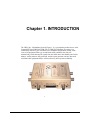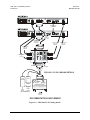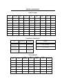
1
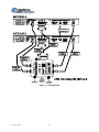
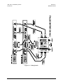
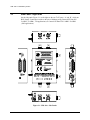
CRS-100
1:1 Redundancy Switch Operation Manual
(Accessory Product for use only with
Comtech EFData CDM-500/550/550T Modems)
Part Number MN/CRS100.IOM
Revision 2
Errata A
Comtech EFData Documentation Update
Subject:
Change Part No. for AUX Cable
Date:
Document:
January 6, 2006
CRS-100 1:1 Redundancy Switch Operation Manual, Revision 2,
dated November 1, 2005
MN/CRS100.EA2
Attach this page to page 2-3
Part Number:
Collating Instructions:
Comments:
Revised Figure 2-1 to change AUX cable part number to read:
Change Specifics:
Filename: T_ERRATA
1
COMTECH PART NO.
PL/WR9320-1
Figure 2-1. Cabling Details
Filename: T_ERRATA
2
Errata B
Comtech EFData Documentation Update
Subject:
Change Part No. for AUX Cable
Date:
Document:
January 6, 2006
CRS-100 1:1 Redundancy Switch Operation Manual, Revision 2,
dated November 1, 2005
MN/CRS100.EB2
Attach this page to page 2-4
Part Number:
Collating Instructions:
Comments:
Revised highlighted AUX Serial Cable part number to read:
Change Specifics:
The following cable assemblies are supplied with the CRS-100 as shown in Figure 2-1:
Quantity 1, Comtech EF Data P/N PL/WR9320-1 (Auxiliary Serial Cable)
Quantity 2, Comtech EF Data P/N CA/WR0056 (Universal Data Interface Cable) And:
Quantity 4, Comtech EF Data P/N CA/BNC 75Ω ( 75Ω IF Cable) or:
Quantity 4, Comtech EF Data P/N CA/BNC 50Ω ( 50Ω IF Cable)
The CRS-100 is designed to work equally well with either 50 or 75 Ω systems, and Users
should ensure that they order the correct IF cable sets when placing their order with the
Factory.
Filename: T_ERRATA
1
CRS-100
1:1 Redundancy Switch Operation Manual
(Accessory Product for use only with
Comtech EF Data CDM-500/550/550T Modems)
Comtech EF Data is an ISO 9001
Registered Company
Part Number MN/CRS100.IOM
Revision 2
November 1, 2005
Copyright © Comtech EF Data, 2000. All rights reserved. Printed in the USA.
Comtech EF Data, 2114 West 7th Street, Tempe, Arizona 85281 USA, (480) 333-2200, FAX: (480) 333-2161.
Customer Support
Contact the Comtech EF Data Customer Support Department for:
• Product support or training
• Information on upgrading or returning a product
• Reporting comments or suggestions concerning manuals
A Customer Support representative may be reached at:
Comtech EF Data
Attention: Customer Support Department
2114 West 7th Street
Tempe, Arizona 85281 USA
480.333.2200 (Main Comtech EF Data Number)
480.333.4357 (Customer Support Desk)
480.333.2161 FAX
or, E-Mail can be sent to the Customer Support Department at:
[email protected]
Contact us via the web at www.comtechefdata.com.
1. To return a Comtech EF Data product (in-warranty and out-of-warranty) for
repair or replacement:
2. Request a Return Material Authorization (RMA) number from the Comtech EF
Data Customer Support Department.
3. Be prepared to supply the Customer Support representative with the model
number, serial number, and a description of the problem.
4. To ensure that the product is not damaged during shipping, pack the product in
its original shipping carton/packaging.
5. Ship the product back to Comtech EF Data. (Shipping charges should be
prepaid.)
For more information regarding the warranty policies, see Warranty Policy, p. ix.
ii
Table of Contents
CHAPTER 1.
INTRODUCTION ................................................................................ 1–1
CHAPTER 2.
INSTALLATION ................................................................................. 2–1
2.1
Unpacking ...................................................................................................................................................2–1
2.2
Mounting .....................................................................................................................................................2–1
2.3
Configuration..............................................................................................................................................2–2
2.4
Connect External Cables............................................................................................................................2–2
2.5
CRS-100/CIC-50 Cabling Details..............................................................................................................2–5
CHAPTER 3.
PHYSICAL DESCRIPTION................................................................ 3–1
3.1
Front Panel..................................................................................................................................................3–1
3.2
Rear Panel ...................................................................................................................................................3–1
3.3
Side Panel - Right Side ...............................................................................................................................3–2
3.4
Side Panel - Left Side .................................................................................................................................3–3
CHAPTER 4.
FUNCTIONAL DESCRIPTION........................................................... 4–1
CHAPTER 5.
CONNECTOR PINOUTS ................................................................... 5–1
iii
CRS-100 1:1 Redundancy Switch
Preface
CHAPTER 6.
Revision 2
MN/CRS100.IOM
OPERATION ...................................................................................... 6–1
6.1
AUTOMATIC OPERATION....................................................................................................................6–1
6.1.1 INFO (Information)..................................................................................................................................6–1
6.1.2 (INFO) MISC (Miscellaneous information)...........................................................................................6–2
6.1.3 (CONFIG) MASK (Alarm mask) ..........................................................................................................6–3
6.2
Manual Operation ......................................................................................................................................6–4
6.2.1 UTIL (Utility) ........................................................................................................................................6–4
6.2.2 (UTIL) MAN-1:1 (Manual 1:1 switchover) ...........................................................................................6–4
CHAPTER 7.
SUMMARY OF SPECIFICATIONS .................................................... 7–1
iv
CRS-100 1:1 Redundancy Switch
Preface
Revision 2
MN/CRS100.IOM
About this Manual
This manual provides installation and operation information for the Comtech EF Data
CRS-100 1:1 Redundancy Switch. This is a technical document intended for earth station
engineers, technicians, and operators responsible for the operation and maintenance of
the CRS-100 1:1 Redundancy Switch.
Conventions and References
Cautions and Warnings
CAUTION
CAUTION indicates a hazardous situation that, if not avoided, may result in
minor or moderate injury. CAUTION may also be used to indicate other
unsafe practices or risks of property damage.
WARNING indicates a potentially hazardous situation that, if not avoided,
could result in death or serious injury.
WARNING
IMPORTANT indicates a statement that is associated with the task
being performed. .
IMPORTANT
Metric Conversion
Metric conversion information is located on the inside back cover of this manual. This
information is provided to assist the operator in cross-referencing English to Metric
conversions.
Trademarks
Other product names mentioned in this manual may be trademarks or registered
trademarks of their respective companies and are hereby acknowledged.
Reporting Comments or Suggestions Concerning this Manual
Comments and suggestions regarding the content and design of this manual will be
appreciated. To submit comments, please contact the Comtech EF Data Technical
Publications Department: [email protected]
v
CRS-100 1:1 Redundancy Switch
Preface
Revision 2
MN/CRS100.IOM
IMPORTANT INFORMATION –
PLEASE READ BEFORE INSTALLATION AND USE
Safety Notices
Electrical Safety
The CRS-100 1:1 Redundancy Switch has been shown to comply with the following
safety standard:
EN 60950:
Safety of Information Technology Equipment, including electrical
business machines
The equipment is rated for operation at +12 volts DC and -12 volts DC.
It has a maximum power consumption of 3.2 watts, and draws a
maximum of 160 mA at +12 volts DC and 100 mA at -12 volts DC. The
power supply current is, in all circumstances, supplied by either a single
Comtech CDM-500/550/550T Modem, or a pair of these Modems.
The User should observe the following instructions:
Equipment Connection
The CRS-100 is designed for operation ONLY with Comtech CDM-500, CDM-550 or
CDM-550T Modems. These Modems supply DC operating current (electronically fused
and protected) and control signals for the correct functioning of this unit. Connection to
other manufacturer’s equipment could result in damage to the unit.
Environmental
The CRS-100 must not be operated in an environment where the unit is exposed to
extremes of temperature outside the ambient range 0 to 50C (32 to 122F), precipitation,
condensation, or humid atmospheres above 95% RH, altitudes (un-pressurised) greater
than 2000 metres, excessive dust or vibration, flammable gases, corrosive or explosive
atmospheres.
vi
CRS-100 1:1 Redundancy Switch
Preface
Revision 2
MN/CRS100.IOM
Operation in vehicles or other transportable installations which are equipped to provide a
stable environment is permitted. If such vehicles do not provide a stable environment,
safety of the equipment to EN60950 may not be guaranteed
Telecommunications Terminal Equipment Directive
In accordance with the Telecommunications Terminal Equipment Directive 91/263/EEC,
this equipment should not be directly connected to the Public Telecommunications
Network.
EMC (Electromagnetic Compatibility)
The CRS-100 1:1 Redundancy Switch has been demonstrated, by independent testing, to
comply with the following standards:
Emissions:
EN 55022 Class B - Limits and methods of measurement of radio
interference characteristics of Information Technology Equipment.
FCC Part 15 Class B
Immunity:
EN 50082 Part 1 - Generic immunity standard, Part 1: Domestic,
commercial and light industrial environment.
In order that the CRS-100 continues to comply with these standards, observe the
following instructions:
•
Connections to the transmit and receive IF ports (BNC female connectors) should
be made using a good quality coaxial cable - for example RG58/U (50 Ω) or
RG59/U (75 Ω).
•
All 'D' type connectors attached to the unit must have back-shells which provide
continuous metallic shielding. Cable with a continuous outer shield (either foil or
braid, or both) must be used, and the shield must be bonded to the back-shell.
•
The equipment must be operated with its cover on at all times. If it becomes
necessary to remove the cover, the User should ensure that the cover is correctly
re-fitted before normal operation commences.
vii
CRS-100 1:1 Redundancy Switch
Preface
Revision 2
MN/CRS100.IOM
viii
CRS-100 1:1 Redundancy Switch
Preface
Revision 2
MN/CRS100.IOM
Warranty Policy
This Comtech EF Data product is warranted against defects in material and workmanship
for a period of two years from the date of shipment. During the warranty period, Comtech
EF Data will, at its option, repair or replace products that prove to be defective.
For equipment under warranty, the customer is responsible for freight to Comtech EF
Data and all related custom, taxes, tariffs, insurance, etc. Comtech EF Data is responsible
for the freight charges only for return of the equipment from the factory to the customer.
Comtech EF Data will return the equipment by the same method (i.e., Air, Express,
Surface) as the equipment was sent to Comtech EF Data.
Limitations of Warranty
The foregoing warranty shall not apply to defects resulting from improper installation or
maintenance, abuse, unauthorized modification, or operation outside of environmental
specifications for the product, or, for damages that occur due to improper repackaging of
equipment for return to Comtech EF Data.
No other warranty is expressed or implied. Comtech EF Data specifically disclaims the
implied warranties of merchantability and fitness for particular purpose.
Exclusive Remedies
The remedies provided herein are the buyer's sole and exclusive remedies. Comtech EF
Data shall not be liable for any direct, indirect, special, incidental, or consequential
damages, whether based on contract, tort, or any other legal theory.
Disclaimer
Comtech EF Data has reviewed this manual thoroughly in order that it will be an easy-touse guide to your equipment. All statements, technical information, and
recommendations in this manual and in any guides or related documents are believed
reliable, but the accuracy and completeness thereof are not guaranteed or warranted, and
they are not intended to be, nor should they be understood to be, representations or
warranties concerning the products described. Further, Comtech EF Data reserves the
right to make changes in the specifications of the products described in this manual at any
time without notice and without obligation to notify any person of such changes.
If you have any questions regarding your equipment or the information in this manual,
please contact the Comtech EF Data Customer Support Department.
ix
Chapter 1. INTRODUCTION
The CRS-100 1:1 Redundancy Switch (Figure 1-1) is a companion product for use with
Comtech EF Data CDM-500, CDM-550 or CDM-550T Modems. Its purpose is to
continuously monitor a pair of modems (in a redundant configuration) so that, in the
event of an equipment failure (or an undesired traffic condition), the unit will
automatically switch data and IF signals from the failed unit to the Standby unit. In this
manner, traffic paths are fully protected, and the system operator can have increased
confidence that equipment failures will not adversely affect system availability.
Figure 1-1. CRS-100
MN/CRS100.IOM
1–1
CRS-100 1:1 Redundancy Switch
Introduction
Revision 2
MN/CRS100.IOM
Accordingly, a 1:1 system comprises an Online Modem, a Standby Modem, and the
CRS-100 Switch.
WARNING
Note that the CRS-100 has been designed specifically as an accessory
product for the Comtech EF Data CDM-500, CDM-550 and CDM-550T
Modems, and should not be used with any other manufacturer’s equipment.
The CRS-100 includes, as standard, a universal data interface which eliminates the need
to exchange interface cards for different applications. The interfaces supported include
EIA-422 (EIA530) DCE, V.35 DCE, synchronous EIA-232 DCE, asynchronous EIA-232
(at data rates up to 56 kbaud) and X.21 DTE and DCE. The User does not have to
configure the interface type - control signals from the Modems automatically perform the
selection.
Clock and Data signals in the Tx direction are buffered and fed to both Modems in the
pair, simultaneously. The Rx IF signal is split and fed to both Modems. This means that
both Modems see identical Tx and Rx traffic signals all the time, which permits the CRS100 to continuously compare the fault status of both Modems. If the CRS-100 sees an
identical fault on both Modems at the same time, it will infer that the fault condition
exists in the external system, and eliminate an un-necessary switchover.
Only one Modem in the pair (the Online unit) is permitted to transmit its IF carrier signal
at any one instant. For total security, the Offline Modem mutes its TX carrier, and the
CRS-100 provides further isolation by using an RF relay within the unit. Unlike some
other 1:1 redundancy systems, which use a passive power combiner for this function (and
hence lose approximately 3.5 dB in output power level) the CRS-100 does not introduce
any attenuation of output signal level.
A very significant feature of the CRS-100 redundancy system is the Auxiliary Serial
connection between the two Modems in the pair. When the appropriate cable connects
the two modems, the Online unit will interrogate the Standby unit at regular intervals, to
determine its configuration. If a difference in configuration is detected, the Online unit
will then automatically re-configure the Standby unit, so that the configurations are
always synchronized. This has the advantage that if the Standby unit is replaced, it does
not have to be re-programmed to match the Online unit - the process is entirely
automatic.
In addition to being able to manually force a switchover, (from either the front panel of
the Online modem, or via the remote control bus) the User may choose the conditions
which cause an automatic switchover. This is controlled by two switches at the side of the
unit, and the User can select between Unit faults only, Unit faults or Receive Traffic
faults, Unit faults or Transmit Traffic faults, or all three. This provides a great deal of
flexibility in the operation of the Switch.
IMPORTANT
Read this Operations Manual in conjunction with the Manual for the
CDM-500, CDM-550 or CDM-550T, as details of the operation of that
equipment is not covered in this document.
1–2
MN/CRS100.IOM
Chapter 2. INSTALLATION
2.1
Unpacking
Inspect shipping containers for damage. If shipping containers are damaged, they should be kept
until the contents of the shipment have been carefully inspected and checked for normal
operation.
Remove the packing list from the outside of the shipping carton. Open the carton and remove the
contents, checking the contents against the packing list. Verify completeness of the shipment and
that the unit functions correctly. If damage is evident, contact the carrier and Comtech EF Data
immediately and submit a damage report. Be sure to keep all shipping materials for the carrier's
inspection.
If the unit needs to be returned to Comtech EF Data, please use the original shipping container.
2.2
Mounting
The CRS-100 is designed to be self-supporting at the rear of the two CDM-500/550/550T modems
which it is connected to. The two data cables (Comtech EF Data Part Number CA/WR0056)
provide this support, but in most rack installations additional support can be provided by physically
anchoring the connecting cables.
2–1
CRS-100 1:1 Redundancy Switch
Introduction
2.3
Revision 2
MN/CRS100.IOM
Configuration
There are only two configuration switches to set, which are located on the left-hand side of the
unit, when viewed from the front. These two switches control the conditions which initiate an
automatic switchover. Consult the following sections on how to set these switches.
2.4
Connect External Cables
Figure 2-1 shows how to connect a pair of modems together with the CRS-100.
2–2
CRS-100 1:1 Redundancy Switch
Introduction
Revision 2
MN/CRS100.IOM
Figure 2-1. Cabling Details
2–3
CRS-100 1:1 Redundancy Switch
Introduction
Revision 2
MN/CRS100.IOM
The following cable assemblies are supplied with the CRS-100 as shown in Figure 2-1 :
Quantity 1, Comtech EF Data P/N CA/WR0055 (Auxiliary Serial Cable)
Quantity 2, Comtech EF Data P/N CA/WR0056 (Universal Data Interface Cable) And:
Quantity 4, Comtech EF Data P/N CA/BNC 75Ω ( 75Ω IF Cable) or:
Quantity 4, Comtech EF Data P/N CA/BNC 50Ω ( 50Ω IF Cable)
The CRS-100 is designed to work equally well with either 50 or 75 Ω systems, and Users
should ensure that they order the correct IF cable sets when placing their order with the
Factory.
WARNING
It is extremely important to designate the two Modems as the ‘A’ Unit and
the ‘B’ unit. When two units are stacked together, the top unit will be ‘A’,
and the bottom unit will be ‘B’.
It is essential to ensure that the IF connections, both Rx and Tx, are made correctly, i.e.
the Tx IF from Unit ‘A’ connects to the Tx IF port ‘A’ on the CRS-100, and Unit ‘B’ to
‘B’, and the same for the Rx IF connections. Failure to observe this requirement will
result in the system malfunctioning.
IMPORTANT
When connecting the Universal Data Interface cable between the
CRS-100 and the modems, please ensure that screw locks on the ‘D’
type connectors are securely fastened. This will prevent the accidental
un-mating of the cable, particularly when a Standby unit is being
removed or replaced.
2–4
CRS-100 1:1 Redundancy Switch
Introduction
2.5
Revision 2
MN/CRS100.IOM
CRS-100/CIC-50 Cabling Details
Figure 2-2 shows how to connect the CIC-50 T1/E1 Interface Converter to the installation.
Quantity 1, Comtech EF Data P/N CA/WR9680-1 (CIC-50 Adapter 25-pin M-F)
Quantity 2, Comtech EF Data P/N AC18W01P01 (Power Supply Unit)
2–5
CRS-100 1:1 Redundancy Switch
Introduction
Revision 2
MN/CRS100.IOM
25 PIN D MALE
COMTECH EFDATA PART #
PL/WR9320-1
(AUX SERIAL CABLE)
25 PIN D MALE
COMTECH EFDATA PART #
CA/WR0056
(UNIVERSAL DATA
INTERFACE CABLE)
COMTECH EFDATA PART #
CA/WR0056
(UNIVERSAL DATA
INTERFACE CABLE)
COMTECH EFDATA PART #
CA/BNC 75 OHM
OR
CA/BNC 50 OHM
COMTECH EFDATA PART #
CA/BNC 75 OHM
OR
CA/BNC 50 OHM
25 PIN D FEMALE
COMTECH EFDATA PART #
CA/BNC 75 OHM
OR
CA/BNC 50 OHM
COMTECH EFDATA PART #
CA/BNC 75 OHM
OR
CA/BNC 50 OHM
25 PIN D MALE
Receive IF
Transmit IF
COMTECH EFDATA PART #
CA/WR9680-1
(CIC-50 ADAPTER)
CRS-100 / CIC-50 CABLING DETAILS
12V DC
PSU #2
(OPTIONAL)
12V DC
25 PIN D FEMALE
PSU #1
COMTECH EFDATA PART #
PS/AC18W01P01
(CIC-50 PSU)
TO AC
TO AC
MAINS
MAINS
( IEC CONNECTOR )
User Data
Interface
DOCUMENTATION SUPPLEMENT
Figure 2-2. CRS-100/CIC-50 Cabling Details
2–6
Chapter 3. PHYSICAL DESCRIPTION
The CRS-100 is constructed as a free-standing module measuring 1.7H x 5.7W x 4.1D
inches (4.3H x 14.5W x 10.4D cm), not including connectors.
3.1
Front Panel
On the front panel (Figure 3-1) of the unit is the main Data Interface connector, a 25 pin
‘D’ type female, and the main Tx and Rx IF connectors, which are BNC female. The pin
connections for the Data Interface connector are shown in Section 6. Also on the front
panel are two LEDs, marked ‘A Online’ and ‘B Online’. Only one of these LEDs will
illuminated at any given time, and gives a visual indication of which of the two units is
presently carrying traffic.
REMEMBER!
The top unit is ‘A’
The bottom unit is ‘B’
3.2
Rear Panel
On the rear panel (Figure 3-1) of the unit are the two Data Interface connectors for the
‘A’ and ‘B’ units, each being 25 pin ‘D’ type male. These are connected to the Modems
using the two supplied cables, Comtech EF Data P/N CA/WR0056 (Universal Data
Interface Cable). Also on the rear panel is a ground stud, which may be used, if desired,
to bond the chassis of the unit to the system ground.
MN/CRS100.IOM
3–1
CRS-100 1:1 Redundancy Switch
3.3
Side Panel - Right Side
On the side panel (Figure 3-1) to the right are the two Tx IF ports, ‘A’ and ‘B’, which are
BNC female. Connection is made to the pair of Modems using Comtech EF Data P/N
CA/BNC 75 OHM ( 75Ω applications) or Comtech EF Data P/N CA/BNC 50 OHM
( 50Ω applications).
Figure 3-1. CRS-100 – Side Panels
3–2
MN/CRS100.IOM
CRS-100 1:1 Redundancy Switch
\Physical Description
3.4
Revision 2
MN/CRS100.IOM
Side Panel - Left Side
On the side panel (Figure 3-1) to the left are the two Receive IF ports, ‘A’ and ‘B’, which
are both BNC female. Connection is made to the pair of Modems using Comtech EF Data
P/N CA/BNC 75 OHM ( 75 Ωapplications) or Comtech EF Data P/N CA/BNC 50 OHM
( 50 Ω applications).
Additionally, a small opening near the rear of the unit provides access to two switches,
which determine the conditions dictating an automatic switchover. This is described in
detail in Chapter 7.
MN/CRS100.IOM
3–3
CRS-100 1:1 Redundancy Switch
This page has been intentionally left blank.
3–4
MN/CRS100.IOM
Chapter 4. FUNCTIONAL
DESCRIPTION
The CRS-100 connects to two modems, an Online unit, and a Standby unit, monitors the
fault status of these two units, and controls the routing of data and IF signals to and from
the two units. In the case of an equipment failure, switching automatically takes place to
protect the traffic circuit. At the heart of the CRS-100 is a Controller State Machine,
which is responsible for fault monitoring and control of switching functions. It is
implemented in a CPLD.
The unit derives its operating power from the two modems - Online and Standby. A diode
sharing arrangement, with a current sharing circuit ensures that in normal operation
power is taken equally from the two modems. However, in the event that one of the two
units is removed, the remaining modem can supply all of the current requirement. The
Modems supply +12 volts DC (at a combined total of 160 mA max) and -12 volts DC (at
a combined total of 100 mA max). Maximum power consumption occurs in either a V.35
or EIA-422 interface mode. Power consumption in EIA-232 modes is approximately
40% of the maximum values. The modem employ electronic fuses, which prevent
excessive current from being drawn by the CRS-100, should an anomalous condition
occur.
Transmit, Clock, and Data signals entering the unit via the Data Interface are buffered
and fed to both units simultaneously. This ensures that the Standby unit sees the same
traffic conditions as the Online Unit. Receive Data and Clock signals coming from the
Online Modem are routed, using signal relays, to the Data Interface. In the event that a
switchover occurs, these relays switch so the Standby unit then supplies the Data and
Clock signals.
As only one Modem in the pair (the Online unit) is permitted to transmit its IF carrier
signal at any one instant, the Standby unit is forced to disable its TX carrier, by asserting
the TX Carrier Off signal at the Data Interface. In addition, the CRS-100 provides further
isolation (and security) by using an RF relay within the unit. Unlike some other 1:1
redundancy systems, which use a passive power combiner on the two Tx IF ports (and
Rev. 1.2
4–1
Functional Description
CRS-100 1:1 Redundancy Switch
hence lose approximately 3.5 dB in output power level) the CRS-100 does not introduce
any attenuation of output signal level.
The Rx IF signal is fed to both units simultaneously, using an internal power divider.
This does introduce a loss of approximately 3.5 dB, but given the wide dynamic range of
the demodulator in both the CDM-500 and the CDM-550, this is not considered to be a
problem. The advantage of this scheme is that the demodulators in both Online and
Standby units are locked, and therefore, if a switchover does occur, there will be no delay
while waiting for the demodulator to acquire lock, which greatly speeds the time for the
switchover to occur.
Fault status information is fed from each of the two modems, via the Data Interface
connector. The Controller State Machine decides, based on the fault status, which of the
two units, ‘A’ or ‘B’ is to be the Online unit. It will assert a control signal to the Standby
unit, which mutes its Tx IF carrier, and simultaneously indicates to the microcontroller
within the Standby unit that the unit is no longer ‘Online’. This results in the ‘Online’
LED on the front panel of the unit being extinguished. This status is also reported over
the remote control bus, so an external M&C system can determine the state of the
redundancy system. At the same time, a GREEN LED will illuminate on the front of the
CRS-100 to indicate whether the ‘A’ or ‘B’ unit is Online.
The User determines the conditions which cause an automatic switchover. This is
controlled by two switches at the side of the unit, and the User can select between Unit
faults only, Unit faults or Receive Traffic faults, Unit faults or Transmit Traffic faults, or
all three. This is covered in detail in Section 7. With the ‘bridging’ architecture of the
CRS-100 (whereby identical traffic signals are routed to both Online and Standby units)
the Controller State Machine can avoid un-necessary switchovers. By examining the fault
status of both units, it can infer if the fault is external to the system.
For example, suppose that the CRS-100 has been configured to switch following Unit
faults or Transmit Traffic faults, and that the modems are configured for external clock
operation. Now suppose that the external equipment (network, mux, router, etc) fails.
The standby and the Online units will show a Transmit Traffic fault (No Clock Detected
from Terrestrial Port). The CRS-100 Controller State Machine will see that these faults
have occurred at the same time (in fact, within a 0.5 second window) and infers that the
fault is external. Therefore, no un-necessary switchover is initiated.
4–2
Rev. 1.2
Chapter 5. CONNECTOR PINOUTS
Table 5-1. Data Connector - 25 Pin ‘D’ Type Female
Pin
Generic Signal description
Direction
EIA-422/
EIA 530
V.35
EIA-232
Circuit
No
1
Shield
-
Shield
FG
AN
101
2
Transmit Data A
DTE to Modem
SD A
SD A
BA
103
3
Receive Data A
Modem to DTE
RD A
RD A
BB
104
7
Signal Ground
-
SG
SG
AB
102
8
Receiver Ready A
Modem to DTE
RR A
RLSD *
CF
109
9
Receive Clock B
Modem to DTE
RT B
SCR B
-
115
10
Receiver Ready B
Modem to DTE
RR B
-
-
109
11
Transmit Clock B
DTE to Modem
TT B
SCTE B
-
113
12
Internal Transmit Clock B
Modem to DTE
ST B
SCT B
-
114
14
Transmit Data B
DTE to Modem
SD B
SD B
-
103
15
Internal Transmit Clock A
Modem to DTE
ST A
SCT A
DB
114
16
Receive Data B
Modem to DTE
RD B
RD B
-
104
17
Receive Clock A
Modem to DTE
RT A
SCR A
DD
115
23
External Carrier Off
(EIA-232 ‘1' or TTL ‘low’ )
DTE to Modem
-
-
-
-
24
Transmit Clock A
DTE to Modem
TT A
SCTE A
DA
113
NOTES:
* Receiver ready is an EIA-232-level control signal on a V.35 interface
‘B’ signal lines are not used for EIA-232 applications
For X.21 operation, use the EIA-422 pins, but ignore Receive Clock if the Modem is DTE, and ignore Transmit clocks if the
Modem is DCE
Rev. 1.2
5–1
Connector Pinouts
CRS-100 1:1 Redundancy Switch
For correct operation of the CRS-100, the Modems must have the
following Firmware versions installed:
IMPORTANT
CDM-500 - Version 1.18 or later
CDM-550 - Version 1.10 or later
CDM-550T - Version 1.04 or later
If the modems do not meet this requirement, please contact the factory
to arrange for a free upgrade to be sent to you.
5–2
Rev. 1.2
Chapter 6. OPERATION
6.1
AUTOMATIC OPERATION
Having connected the cables in accordance with the instructions and diagram in Section
3.4, the User is now ready to put the system into operational use. Before proceeding, the
User should check that the Auxiliary Serial link between the two units is functioning
correctly. From the front panel of the Online unit, access the main menu, then select
INFO.
6.1.1
INFO (Information)
INFO:ID TX RX BUFF EDMAC
REMCONT MASK MISC(ENTER)
Highlight MISC using the [←] [→] arrow keys, then press [ENTER].
MN/CRS100.IOM
6–1
CRS-100 1:1 Redundancy Switch
Operation
6.1.2
Revision 2
MN/CRS100.IOM
(INFO) MISC (Miscellaneous information)
MISC: IF-LOOP 50 OHMS
1:1 LINK=ACTIVE ONLINE
On the bottom line, the screen should show that the 1:1 link is active. If it does not, then
check that the cable is correctly installed before continuing.
Comtech EF Data recommends that the User decide upon which condition is desired to
initiate a switchover, and to correctly configure the two switches on the left side of the
CRS-100. The User can choose from the following four conditions:
1) Unit faults only (both switches in the Down , or ‘OFF’ position).
2) Unit faults or Tx Traffic faults (the left switch in the Up, or ‘ON’ position)
3) Unit faults or Rx Traffic faults (the right switch in the Up, or ‘ON’ position)
4) Unit faults or Rx or Tx faults (both switches in the Up or ‘ON’ position)
All of the possible fault conditions are listed below:
Unit faults:
Power supply fault, 5 volts
Power supply fault , 12 volts
Power supply fault, -5 volts
Power supply fault, 18 volts
Power supply fault, -12 volts
RAM load fail
Tx synthesiser lock
Rx synthesiser lock
Power cal Checksum error
Tx Traffic faults
No Clock from terrestrial interface (masked when on Internal Clock)
Tx FIFO slip
AIS detected on incoming data *
Rx Traffic status:
Demodulator unlocked
AGC Alarm - signal level too high *
Frame sync lost (Reed-Solomon or EDMAC)
Buffer Underflow *
Buffer Overflow *
AIS detected on incoming data *
Eb/No threshold exceeded *
Those alarms marked with an asterix (*) can be masked by the User. This is
accomplished by selecting CONFIG from the main menu of the Online unit, after which
the following menu will be displayed:
6–2
MN/CRS100.IOM
CRS-100 1:1 Redundancy Switch
Operation
6.1.3
Revision 2
MN/CRS100.IOM
(CONFIG) MASK (Alarm mask)
ALARM MASK: AGC
RX-AIS BUF-SLIP
Eb/No
TX-AIS
The user is prompted to select AGC, Eb/No, RX-AIS, BUF-SLIP, or TX-AIS, using the
[←] [→] arrow keys, then to press [ENTER].
Following the selection of the alarm to be masked, the User is then presented with a submenu, where the choice between ‘ACTIVE’ and ‘MASKED’ is made.
Comtech EF Data recommends that for most applications the
CRS-100 should be configured to switch on Unit faults only.
IMPORTANT
MN/CRS100.IOM
The system, now configured, is ready to be put into service.
6–3
CRS-100 1:1 Redundancy Switch
Operation
6.2
Revision 2
MN/CRS100.IOM
Manual Operation
There are two ways to force a manual switchover in a 1:1 system. First, from the front
panel of the Online unit, select the Utility screen:
6.2.1
UTIL (Utility)
UTILITY: SET-RTC DISPLAY
MAN-1:1 RECENTER-BUF ID
The user should select MAN-1:1, then press [ENTER].
6.2.2
(UTIL) MAN-1:1 (Manual 1:1 switchover)
PRESS ENT TO FORCE THIS
UNIT TO STDBY (1:1 ONLY)
If the unit is part of a 1:1 redundant pair of modems, and this unit is currently Online,
pressing [ENTER] will cause the unit to switch to standby.
Observe that this only works from the front panel of the Online unit. If this is carried out
from the front panel of the Standby unit, it will not cause a switchover.
The second method is via the remote control bus. Sending the ASCII string
<XXXX/FSW=<CR> to the Online unit (where XXXX is the address of the Online unit)
will force a switchover. This can be accomplished either by the User’s own software, or
using Comtech EF Data’s own Monitor and Control Software package.
WARNING
If it becomes necessary to remove a Standby unit from the redundancy
system, turn the power off before attempting to disconnect any of the cables.
Similarly, when replacing a Standby unit, fully connect all of the cables
before applying power.
AND REMEMBER !!
The top unit is ‘A’
The bottom unit is ‘B’
6–4
MN/CRS100.IOM
Chapter 7. SUMMARY OF
SPECIFICATIONS
Equipment Type
Modems
Supported
Operating Modes
Architecture
Switch Conditions
Fault detection
time
Switchover time
Data Interface
Types
Pinout
IF Switching
/Splitting
IF Impedance
IF Connectors
MN-CRS100.IOM
1:1 Redundancy Switch
CDM-500, CDM-550 and CDM-550T Digital Satellite Modems
Fully automatic
Manual (via the front panel of the Online Modem, or via the Modem’s
remote control interface )
Full bridging architecture, with configuration synchronization
Tx Clock and Data signals fed to both Online and Standby units
Rx IF signal fed to both Online and Standby units
Continuous fault comparison of Online and Standby units
The configuration of Online and Standby units synchronized via the
Auxiliary Serial link between the two Modems
Switchover initiated following:
Unit faults only, or:
Unit faults or Receive Traffic Faults, or:
Unit faults or Transmit Traffic Faults, or:
Unit faults or Receive or Transmit Traffic Faults
0.5 seconds maximum
Within 0.1 seconds of fault detection
EIA-422/EIA530 DCE (also supports X.21 DCE and DTE)
V.35 DCE
Synchronous EIA-232
Asynchronous EIA-232 (maximum data rate: 56 kbaud, and when
used with CDM-550 or CDM-550T only)
Automatic selection performed by modem
Per EIA-530 (25 pin ‘D’ type female)
Tx IF: Switched by RF relay (0.3 dB max loss)
Rx IF: Passive power splitting (3.5 dB max loss)
Both 50 and 75 Ω supported
BNC female
7–1
CRS-100 1:1 Redundancy Switch
Summary Of Specifications
IF Frequency
range
Weight
Dimensions
Power
requirements
Approvals
Revision 2
MN-CRS100.IOM
52 - 176 MHZ
(works with both 70 and 140 MHZ Modem IF options)
1.1 lbs (0.5 kg)
1.7H x 5.7W x 4.1D inches
(4.3H x 14.3W x 10.4D cm)
(Excluding connectors)
3.2 Watts maximum
+ 12 volts DC @ 160 mA (max)
-12 volts DC @ 100 mA (max)
(Power is supplied by the Online and Standby Modems, and the unit
current shares when both an ‘A’ and ‘B’ unit are present. These power
supplies are electronically fused and protected.)
CE
7–2
MN-CRS100.IOM
METRIC CONVERSIONS
Units of Length
Unit
Centimeter
Inch
Foot
Yard
Mile
Meter
Kilometer
Millimeter
1 centimeter
—
0.3937
0.03281
0.01094
6.214 x 10⁻⁶
0.01
—
—
1 inch
2.540
—
0.08333
0.2778
1.578 x 10⁻⁵
0.254
—
25.4
1 foot
30.480
12.0
—
0.3333
1.893 x 10⁻⁴
0.3048
—
—
1 yard
91.44
36.0
3.0
—
5.679 x 10⁻⁴
0.9144
—
—
1 meter
100.0
39.37
3.281
1.094
6.214 x 10⁻⁴
—
—
—
1 mile
1.609 x 10⁵
6.336 x 10⁴
5.280 x 10³
1.760 x 10³
—
1.609 x 10³
1.609
—
1 mm
—
0.03937
—
—
—
—
—
—
1 kilometer
—
—
—
—
0.621
—
—
—
Temperature Conversions
° Fahrenheit
Unit
100
F = (C * 1.8) + 32
(water boils)
273.1
—
-459.6° Fahrenheit
C = (F - 32) * 0.555
(water freezes)
—
212° Fahrenheit
Formulas
0
—
32° Fahrenheit
° Centigrade
(absolute 0)
Units of Weight
Gram
Ounce
Avoirdupois
Ounce
Troy
Pound
Avoir.
Pound
Troy
Kilogram
—
0.03527
0.03215
0.002205
0.002679
0.001
1 oz. avoir.
28.35
—
0.9115
0.0625
0.07595
0.02835
1 oz. troy
31.10
1.097
—
0.06857
0.08333
0.03110
1 lb. avoir.
453.6
16.0
14.58
—
1.215
0.4536
1 lb. Troy
373.2
13.17
12.0
0.8229
—
0.3732
1 kilogram
1.0 x 10³
35.27
32.15
2.205
2.679
—
Unit
1 gram
2114 WEST 7TH STREET TEMPE ARIZONA 85281 USA
480 • 333 • 2200 PHONE
480 • 333 • 2161 FAX