1
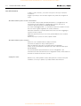
DOWNLOADED FROM WWW.BEOINFO.NL - SECOND LIFE BANG & OLUFSEN
DVD 1
Type 4620
Service Center repair guide
English, German, French, Italian, Spanish
NOT FOR USE AT OTHER WEBSITES THEN WWW.BEOINFO.NL
DOWNLOADED FROM WWW.BEOINFO.NL - SECOND LIFE BANG & OLUFSEN
CONTENTS
Survey of modules ................................................................
How to service ......................................................................
Specification guidelines for service use ..................................
Cautions ...............................................................................
1.1
1.2
1.3
1.5
Brief operation guide ..................................................................
2
Wiring diagram ............................................................................
3
List of available parts ...................................................................
4
Service mode and repair tips .......................................................
English ..................................................................................
German ................................................................................
French ..................................................................................
Italian ...................................................................................
Spanish .................................................................................
5
5.1
5.3
5.5
5.7
5.9
Disassembly ...................................................................................
6
Replacement of PCB1, PCB2 and PCB5 ................................. 6.2
Replacement of PCB998 ....................................................... 6.3
Replacement of loader plate ................................................. 6.4
Insulation test ...............................................................................
English ..................................................................................
German ................................................................................
French ..................................................................................
Italian ...................................................................................
Spanish .................................................................................
NOT FOR USE AT OTHER WEBSITES THEN WWW.BEOINFO.NL
7
7.1
7.2
7.3
7.4
7.5
DOWNLOADED FROM WWW.BEOINFO.NL - SECOND LIFE BANG & OLUFSEN
Survey of modules
J15
I²C
1501
1603
1602
ASD1
1604
1600
J7
J4
PCB998
J6
Switch info out
J10
J1
J5
Key in, +5V and Display control
Switch info in
CD-mech.
Loadermotor
1100
DVDM
Loader
J1
DVD1
Display Board, PCB3
NOT FOR USE AT OTHER WEBSITES THEN WWW.BEOINFO.NL
SMPS, µP, driver
J14
Power supply, PCB1
A/V Board, PCB2
Mains
(shaver),
PCB4
0/6V/12V +AVL etc.
SCART
Analog
audio out
Y/C
CVBS
DATA Dig. Audio (2 x Phono)
R L
(Mini DIN) (Phono) (Mini jack) (Phono)
J4
AVL data
+0V/6V/12V
(pin 8)
CVBS
RGBor Y/C
or YUV
Analog audio
R+L
RGB or CVBS
(Switch)
Survey of modules
1.1
DOWNLOADED FROM WWW.BEOINFO.NL - SECOND LIFE BANG & OLUFSEN
1.2
How to service
How to service
It is possible that service of DVD 1 can be carried out in the customers home, but
is more convenient at the dealers place. A Back-up suitcase is available which
contains the DVD mechanism with ASD1 module and additional modules.
Durchführung von Reparaturen
Reparaturen am DVD 1 können zu Hause beim Kunden durchgeführt werden; sie
lassen sich allerdings bequemer in der Werkstatt des Händlers erledigen. Es ist ein
Reparaturkoffer lieferbar mit DVD-Mechanismus, inklusive ASD1-Modul und
zusätzlichen Modulen.
Comment effectuer la maintenance
Il est possible d’effectuer la maintenance du DVD 1 chez le client mais il est plus
pratique de le faire chez le revendeur. Une valise de sauvegarde contenant le
mécanisme du DVD avec le module ASD1 et des modules supplémentaires est
disponible.
Come effettuare l’assistenza tecnica
È possibile che sia necessario eseguire gli interventi di assistenza tecnica di DVD 1
presso il cliente, tuttavia sarebbe preferibile effettuarli presso la sede dei rivenditori.
È disponibile una valigetta di Back-up che contiene il meccanismo DVD con il
modulo ASD1 nonché i moduli supplementari.
Cómo realizar el servicio
Se puede realizar el servicio del DVD 1 en el hogar del cliente, pero es más
conveniente en los locales del distribuidor. Está disponible una maleta auxiliar que
contiene el mecanismo del DVD con el módulo ASD1 y módulos adicionales.
NOT FOR USE AT OTHER WEBSITES THEN WWW.BEOINFO.NL
DOWNLOADED FROM WWW.BEOINFO.NL - SECOND LIFE BANG & OLUFSEN
Specification guidelines for service use
SPECIFICATION GUIDELINES FOR SERVICE USE
Type
Cabinet finish
Operation
DVD 1
4620
Black, Blue, White, Silver, Red, Green
Close-up operation
Beo 4 remote control via BeoVison recommended
Disc size
Audio frequency response
Playback the following
Signal/noise ratio Audio
DVD Zone
12 cm. - 8 cm
4 -20,000 Hz
DVD-Video, Video CD, CD-A, CD-R, CD-RW
Multistandard PAL/NTSC
≥ 110 dB, A weighted
According to Region
Dimensions W x H x D/Weight
Power supply
Power consumption
38 x 9.7 x 28 cm/4.0 kg
100-240 volts/50/60 Hz
Typical 13 watts / st-by < 1 watt
Accessories
Shelf
Shelf
4134 DVD 1 and V8000 with a MX TV
4132 DVD 1 or V8000 with a MX TV
Connections
AV
Pin 1
Pin 2
Pin 3
Pin 4
Pin 5
Pin 6
Pin 7
Pin 20
Pin 21
Audio R out 1.8V RMS 1k ohm
Not used
Audio L out 1.8V RMS 1k ohm
Audio GND
Blue GND
Not used
Blue out 0.7 Vpp 75 ohms
U out 0.7 Vpp 75 ohms
Data in
0V/6V/12V
Green GND
Not used
Green out 0.7 Vpp 75 ohms
V out 0.7 Vpp 75 ohms
Not used
Red GND
Blanking GND
Red out 0.7 Vpp 75 ohms
C out 0.3 Vpp 75 ohms
Blanking out 75 ohms
Logic 0 = 0V to 0.4V
Logic 1 = 1V to 3V
Video out GND
Video in GND
Composite video out 1 Vpp 75 ohms
Y out 1 Vpp 75 ohms
Not used
Shield
Pin 1
Pin 2
Pin 3
Pin 4
Y GND
C GND
Y out 1 Vpp 75 ohms
C out 0.3 Vpp 75 ohms
Pin 8
Pin 9
Pin 10
Pin 11
Pin 12
Pin 13
Pin 14
Pin 15
Pin 16
Pin 17
Pin 18
Pin 19
Y/C
CVBS
Composite video out 1 Vpp 75 ohms
DATA
AVL data input
AUDIO L & R
Audio L & R out 2 V RMS 1 kohm
DIGITAL OUTPUT
Digital audio output
NOT FOR USE AT OTHER WEBSITES THEN WWW.BEOINFO.NL
1.3
DOWNLOADED FROM WWW.BEOINFO.NL - SECOND LIFE BANG & OLUFSEN
1.4
Specification guidelines for service use
V.TAPE & AV
Pin 1
Audio R out 1V RMS 150 ohms
Pin 2
Audio R in 1V RMS 40k ohms
Pin 3
Audio L out 1V RMS 150 ohms
Pin 4
Audio GND
Pin 5
Blue GND
Pin 6
Audio L in 1V RMS 40k ohms
Pin 7
Blue in 0.7 Vpp 75 ohms
Pin 8
Play voltage:
Pin 9
Green GND
Pin 10
Not used
Pin 11
Green in 0.7 Vpp 75 ohms
Pin 12
Not used
Pin 13
Red GND
Pin 14
Blanking GND
Pin 15
Red in 0.7 Vpp 75 ohms
Pin 16
Blanking in
Pin 17
Video out GND
Pin 18
Video in GND
Pin 19
Composite video out 1 Vpp 75 ohms
Pin 20
Composite video in 1 Vpp 75 ohms
Pin 21
Shield
Logic 0 = 0V to 2V
Logic 1 = 9.5V to 12V (4:3 info)
5V to 7V = 16:9 info
V.TAPE Data in/out
AV Data out
(note 1)
Logic 0 = 0V to 0.4V
Logic 1 = 1V to 3V
R in 75 ohms
Note 1: Pin 15 is also used for C in.
Note 2: Pin 20 is also used for Y in.
VIDEO
Composite video in 1Vpp 75 ohms
L&R
Audio L & R in 0.2V - 2 V RMS >10k ohms
Subject to change without notice
NOT FOR USE AT OTHER WEBSITES THEN WWW.BEOINFO.NL
(note 2)
DOWNLOADED FROM WWW.BEOINFO.NL - SECOND LIFE BANG & OLUFSEN
Cautions
1.5
Caution
The use of any controls, adjustments or procedures other than those specified
herein may result in hazardous radiation exposure.
CLASS 1
LASER PRODUCT
COMPACT
COMPACT
DIGITAL VIDEO
DIGITAL AUDIO
The black and yellow label on the unit serves as a warning that the apparatus
contains a laser system and is classified as a class 1 laser product. The apparatus
must be opened by qualified service person only.
This product incorporates copyright protection technology that is protected by
claims of certain US patents and other intellectual property rights owned by
technology must be authorized by Macrovision Corporation, and is intended for
home and other limited viewing uses only unless otherwise authorized by
Macrovision Corporation. Reverse enginering or disassembly is prohibited.
STATIC ELECTRICITY
MAY DESTROY THE
PRODUCT
Static electricity may destroy the product!
A static-protective field service kit must always be used when replacecement of the
modules takes place.
Please note:
When mains voltage on the TV is required, remove the connection from the TV to
the ESD mat.
NOT FOR USE AT OTHER WEBSITES THEN WWW.BEOINFO.NL
DOWNLOADED FROM WWW.BEOINFO.NL - SECOND LIFE BANG & OLUFSEN
2.1
Brief operation guide
Brief operation guide
Buttons on DVD 1
-
EJECT. Press to open or close the loader.
l n. Press to cue forward or backward during playback.
PLAY. Press to start playback. Press again to pause playback.
V. Press to switch DVD 1 to standby.
Playback of DVD
- Load the disc in DVD 1. Press PLAY to start playback.
DVD disc menu
- Not available on all DVD discs. Press and hold GO (Beo1/Beo4) or press the yellow
button on Beo4 to gain access to special features such as information about the
making of a film, interviews or specially edited scenes.
On-screen tool bar
- Press DISPLAY on Beo1 or the blue button on Beo4 to gain access to the main
functions of DVD 1.
Use l n to select function. Use m p to view setting choices for the function.
Press GO to store the choice and resume playback.
Connections to DVD1
- Set switch according to the connected TV. Please note that:
If connection is made without a 21-pin AV cable set the switch for RGB.
- CVBS if BeoVision AV9000, BeoVision LX/MS/MX.
- Y/C if BeoVision Avant 50Hz, BeoCenter AV5.
- RGB if any other Bang & Olufsen TV.
DIGITAL OUTPUT
DATA
Y/C
CVBS
CVBS
AUDIO L
AUDIO R
RGB
AV
Y/C
- DIGITAL OUTPUT, AUDIO L, AUDIO R.
Used if connecting to a TV without using a 21-pin AV cable. Audio signals.
- DATA, Y/C, CVBS.
Used if connecting to a TV without using a 21-pin AV cable. Data and video signals.
- AV.
Used if connecting to a TV using a 21-pin AV cable. Data, audio and video signals.
Further information regarding daily use
- Please refer to the DVD 1 Guide for further information regarding daily use.
NOT FOR USE AT OTHER WEBSITES THEN WWW.BEOINFO.NL
DOWNLOADED FROM WWW.BEOINFO.NL - SECOND LIFE BANG & OLUFSEN
Brief operation guide
2.2
Overview of On-screen tool bar
Title number
Favourite Track Selection (FTS)
Change to another title by pressing m or p.
Allows you to identify favourite tracks on a particular DVD disc and
Chapter number
store them in the player’s memory.
Change tracks during playback by pressing m or p.
Sound settings
Playback language*
Choose between Stereo and Dolby Surround Sound.
Pause
Choose from the languages available on your particular disc.
Press the red button on Beo4 to be able to change playback language
Press p to pause playback on a particular frame. Press l and n to
during playback.
move between frames, and press GO to resume playback.
Subtitle language*
Slow motion
Choose a subtitle language available on your disc, or choose not to
Press p to pause playback and l or n to start slow motion.
view subtitles. Press the green button on Beo4 to be able to change
Press l or n to adjust speed and press GO to resume playback.
Fast motion
subtitles during playback.
Press p to pause playback and l or n to start fast motion.
Camera angle*
It is possible on some DVD discs to change to a different camera angle.
Press l or n to adjust speed and press GO to resume playback.
Zoom
Time search
Choose the magnification, press GO to enter your choice and use the
Use the numeric key pad on Beo4 to enter the desired start time.
arrow keys to pan back and forth. Press GO to resume playback.
*NOTE! If a function is inactive for your player setup, or if the
disc does not contain a particular option (such as camera angle
on some DVD discs), the function symbol and current setting
will not be highlighted, and p or m for changing settings will
not appear.
1
1
1
1
1
1
1
no
1
no
off
off
1
off
st
Picture settings
- TV SHAPE. Options are: 4:3 LETTERBOX, 4:3 PAN SCAN and 16:9.
- BLACK LEVEL SHIFT. Options are: ON and OFF.
- VIDEO SHIFT. Center picture horizontally with l n.
Picture settings
-
Sound settings
DIGITAL OUTPUT. Options are: OFF, PCM only and ALL.
ANALOG OUTPUT. Options are: STEREO and DOLBY SURROUND.
NIGHT MODE. Options are: ON and OFF.
KARAOKE VOCAL. Options are: ON and OFF.
Sound settings
Subtitles
Other functions
Subtitles
- AUDIO LANGUAGE. Choose between the 16 shown.
- SUBTITLE LANGUAGE. Choose between the 16 shown.
- MENU LANGUAGE. Choose between the 8 shown.
-
Other functions
ACCESS CONTROL. Child Lock, Parental Control and Country settings.
STATUS WINDOW. Options are: ON and OFF.
LOW POWER STANDBY. Options are: ON and OFF.
PBC. Menu for playback of SVCD. Options are: ON and OFF.
NOT FOR USE AT OTHER WEBSITES THEN WWW.BEOINFO.NL
DOWNLOADED FROM WWW.BEOINFO.NL - SECOND LIFE BANG & OLUFSEN
Wiring diagram
3.1
3.1
Wiring diagram
Wiring diagram
NOT FOR USE AT OTHER WEBSITES THEN WWW.BEOINFO.NL
3.1
DOWNLOADED FROM WWW.BEOINFO.NL - SECOND LIFE BANG & OLUFSEN
4.1
List of available parts
4.1
4.1
List of available parts
DVD 1
AVAILABLE PARTS
DVD 1
9001
2
US only
5
4
9001
9002
9003
9004
9005
9006
9007
9008
9009
3400482
3400483
3400484
3400485
3400486
3400487
3358412
3414327
3456239
3375258
3470256
3470257
3452712
3451730
Top cover, black
Top cover, green
Top cover, red
Top cover, white
Top cover, blue
Top cover, grey
Iron chassis
Bottom
Loade plate
Bag w/screws and washers
Side panel, left
Side panel, right
Cover f/sockets
Front panel w/buttons
1Module
8006951 PCB1, Power Supply & Microcomputer
2Module
8006952 PCB2, A/V Board
3Module
8006956 PCB3, Display
4Module
8006957 PCB4, AC Inlet
5Module
8000511 PCB5, Sound Correction (US only)
998Module 8006960 ASD1/DVD Mechanism
8000520 ASD1/DVD Mechanism, US
1
Wire bundles
See wiring diagram page 3.1.
The part no. is printed on the diagram above the wire bundle, as shown.
998
9002
Parts not shown
6100245
6100328
6100248
6100306
6270803
6270804
3395149
3395183
Packing
3396135 Set of foam
3392509 Outer carton
Available documentation
3508476
3508477
3508479
3508480
3508481
3508482
3508483
3508484
3508478
3508485
3508486
9006
9003
9007
Mains lead EU
Mains lead GB
Mains lead AUS
Mains lead US
AV cable
Data cable 10cm w. mini jack
Back-up suitcase
Back-up suitcase, US
9008
9009
9004
9005
3
NOT FOR USE AT OTHER WEBSITES THEN WWW.BEOINFO.NL
User’s Guide, Danish
User’s Guide, Swedish
User’s Guide, English
User’s Guide, German
User’s Guide, Dutch
User’s Guide, French
User’s Guide, Italian
User’s Guide, Spanish
User’s Guide, Finnish
User’s Guide, Portuguese
User’s Guide, Taiwanese
DOWNLOADED FROM WWW.BEOINFO.NL - SECOND LIFE BANG & OLUFSEN
Service mode, English
5.1
Service mode
1
1
1
1
no
off
Picture settings
Sound settings
Subtitles
n
Other functions
p -
ACCESS CONTROL.
STATUS WINDOW.
LOW POWER STANDBY.
PBC.
(C) ‘99-’00 7.XX 000831
P21
4.3.11
MPEG IC SW version:
SW date:
Slash SW version:
Servo IC SW version:
Applikations SW version (1IC1)
- Use the buttons on DVD 1. Remove CD if such is loaded. Then disconnect DVD 1
from the mains.
Press and hold PLAY and l and then reconnect DVD 1 to the mains.
The SW version will appear in the display.
Region setup
- Use the buttons on DVD 1. Remove CD if such is loaded. Then disconnect DVD 1
from the mains. Press and hold l and n and then reconnect DVD 1 to the mains.
The current setting will appear in the display.
Use l n to change Region number. Press PLAY to store the desired number. Wait
approx. 15 sec. until the screen goes blue.
Please note: The number of times Region setting can be changed is limited. If this
limit is exceeded DVD 1 will cease to function.
Country and Region setting:
Australia - 4; Canada - 1; Estonia - 5; Ghana - 5; Hong Kong - 3; Indonesia - 3;
Latvia - 5; Lithuania - 5; Malaysia - 3; Morocco - 5; Nigeria - 5; Singapore - 3;
Taiwan - 8; Thailand - 3; USA - 1
NOT FOR USE AT OTHER WEBSITES THEN WWW.BEOINFO.NL
DOWNLOADED FROM WWW.BEOINFO.NL - SECOND LIFE BANG & OLUFSEN
5.2
Repair tips, English
Repair tips
There is a problem with:
- Picture.
Analog video signals can be measured from PCB71.
For RGB or CVBS measure on 71-1603 or 2J15.
For Y/C measure on 71-1604 or 2J14.
If video signals are OK from PCB71, the fault may be located on PCB2.
- Sound.
Only digital audio signals can be measured from PCB71.
Try playback of an Audio CD. If OK, the fault may be located on PCB71 or PCB94.
If not OK, the fault may be located on PCB2.
- Both picture and sound.
Ensure that all voltages from PCB1 to PCB71 and to PCB2 are OK.
Measure if there is any activity on I2C DATA and I2C CLOCK on 1J6.
- Playback of DVD/CD.
Ensure that all voltages from PCB1 to PCB71 and PCB2 are OK.
Measure if there is any activity on MOTOR and TRAY on 1J1 and 1J10.
- Loader/tray.
Check for any mechanical failures on PCB94.
Measure if there is any activity on MOTOR and TRAY on 1J1 and 1J10.
- Display/Keyboard.
Measure voltage on 1J5. Measure if there is any activity on CS, K DATA and
K CLOCK on 1J5.
Ensure that voltage on key-pins 1J5 pin1-5 is pulled down when pressed.
NOT FOR USE AT OTHER WEBSITES THEN WWW.BEOINFO.NL
DOWNLOADED FROM WWW.BEOINFO.NL - SECOND LIFE BANG & OLUFSEN
Service-Modus, Deutsch
5.3
Service-Modus
1
1
1
1
no
off
Picture settings
Sound settings
Subtitles
n
Other functions
p -
ACCESS CONTROL.
STATUS WINDOW.
LOW POWER STANDBY.
PBC.
(C) ‘99-’00 7.XX 000831
P21
4.3.11
MPEG IC SW version:
SW date:
Slash SW version:
Servo IC SW version:
Anwendungen Version SW (1IC1)
- Benutzen Sie die Tasten am DVD 1! Entnehmen Sie die CD (sofern eingelegt)!
Dann DVD 1 vom Netz trennen.
Drücken Sie die PLAY-Taste und l und halten Sie sie fest, und schließen Sie DVD 1
dann wieder an das Stromnetz an!
Auf dem Display wird nun die SW-Version angezeigt.
Regionale Einstellung
- Benutzen Sie die Tasten am DVD 1! Entnehmen Sie die CD (sofern eingelegt)!
Dann DVD 1 vom Netz trennen. Drücken Sie die l- und n-Tasten und halten Sie
sie fest, und schließen Sie DVD 1 dann wieder an das Stromnetz an! Auf dem
Display erscheint nun die aktuelle Einstellung.
Drücken Sie l n, um die Regionale Nummer zu ändern. Durch Drücken von PLAY
wird die gewünschte Nummer gespeichert. Warten Sie etwa 15 Sek., bis der
Bildschirm blau wird.
Bitte beachten: Die Anzahl der möglichen Veränderungen bei der Regionalen
Einstellung ist begrenzt. Bei Überschreitung der Maximalzahl funktioniert der
DVD 1-Player nicht mehr!
Country and Region setting:
Australia - 4; Canada - 1; Estonia - 5; Ghana - 5; Hong Kong - 3; Indonesia - 3;
Latvia - 5; Lithuania - 5; Malaysia - 3; Morocco - 5; Nigeria - 5; Singapore - 3;
Taiwan - 8; Thailand - 3; USA - 1
NOT FOR USE AT OTHER WEBSITES THEN WWW.BEOINFO.NL
DOWNLOADED FROM WWW.BEOINFO.NL - SECOND LIFE BANG & OLUFSEN
5.4
Reparaturhinweise, Deutsch
Reparaturhinweise
Bei Problemen mit ...
- Bild.
Analoge Videosignale können von PCB71 gemessen werden.
Für RGB bzw. CVBS erfolgt die Messung an 71-1603 bzw. 2J15.
Für Y/C erfolgt die Messung an 71-1604 bzw. 2J14.
Falls die Videosignale von PCB71 i.O. sind, kann der Fehler vielleicht bei PCB2
liegen.
- Tonwiedergabe.
Von PCB71 können ausschließlich digitale Audiosignale gemessen werden.
Versuchen Sie, eine Audio-CD wiederzugeben! Falls dies in Ordnung ist, liegt der
Fehler möglicherweise bei PCB71 oder PCB94.
Falls nicht i.O., liegt der Fehler vielleicht bei PCB2.
- Bild und Ton.
Vergewissern Sie sich, dass alle Spannungen von PCB1 zu PCB71 und zu PCB2 i.O.
sind!
Messen Sie, ob eine Aktivität bei I2C DATA und I2C CLOCK an 1J6 feststellbar ist!
- Wiedergabe von DVD/CD.
Vergewissern Sie sich, dass alle Spannungen von PCB1 zu PCB71 und PCB2 i.O.
sind!
Messen Sie, ob eine Aktivität bei MOTOR und TRAY an 1J1 und 1J10 feststellbar
ist!
- Ladevorrichtung/Schub.
Prüfen Sie auf mechanische Störungen an PCB94.
Messen Sie, ob eine Aktivität bei MOTOR und TRAY an 1J1 und 1J10 feststellbar
ist!
- Display/Tastatur.
Messen Sie die Spannung an 1J5! Messen Sie, ob eine Aktivität bei CS, K DATA
und K CLOCK an 1J5 vorliegt!
Vergewissern Sie sich, dass an den Schlüsselstiften 1J5 Stift 1-5 beim Niederdrücken
Spannung abgezogen wird!
NOT FOR USE AT OTHER WEBSITES THEN WWW.BEOINFO.NL
DOWNLOADED FROM WWW.BEOINFO.NL - SECOND LIFE BANG & OLUFSEN
Mode Entretien, Français
5.5
Mode Entretien
1
1
1
1
no
off
Picture settings
Sound settings
Subtitles
n
Other functions
p -
ACCESS CONTROL.
STATUS WINDOW.
LOW POWER STANDBY.
PBC.
(C) ‘99-’00 7.XX 000831
P21
4.3.11
MPEG IC SW version:
SW date:
Slash SW version:
Servo IC SW version:
Version logiciel d’applications (1IC1)
- Utilisez les touches du DVD 1. Retirez un éventuel CD. Puis débranchez le DVD 1
du secteur.
Appuyez et maintenez enfoncées PLAY et l puis rebranchez le DVD 1 au secteur.
La version du logiciel apparaît dans l’afficheur.
Configuration de la région
- Utilisez les touches du DVD 1. Retirez un éventuel CD. Puis débranchez le DVD 1
du secteur. Appuyez et maintenez enfoncées l et n puis rebranchez le DVD 1 au
secteur. Le réglage actuel apparaît dans l’afficheur.
Utilisez l n pour changer le numéro de région. Appuyez sur PLAY pour mémoriser
le numéro désiré. Attendre environ 15 s que l’écran devienne bleu.
Prière de noter : Le nombre de fois qu’il est possible de changer le réglage de la
région est limité. Si cette limite est dépassée, le DVD 1 s’arrête de fonctionner !
Country and Region setting:
Australia - 4; Canada - 1; Estonia - 5; Ghana - 5; Hong Kong - 3; Indonesia - 3;
Latvia - 5; Lithuania - 5; Malaysia - 3; Morocco - 5; Nigeria - 5; Singapore - 3;
Taiwan - 8; Thailand - 3; USA - 1
NOT FOR USE AT OTHER WEBSITES THEN WWW.BEOINFO.NL
DOWNLOADED FROM WWW.BEOINFO.NL - SECOND LIFE BANG & OLUFSEN
5.6
Astuces de réparation, Français
Astuces de réparation
Il y a un problème avec :
- l’image
Les signaux vidéo analogiques peuvent être mesurés à partir de la PCB71.
Pour RGB ou CVBS, mesurez sur 71-1603 ou 2J15.
Pour Y/C, mesurez sur 71-1604 ou 2J14.
Si les signaux vidéo sont corrects à partir de la PCB71, le défaut peut se trouver sur
la PCB2.
- le son
Seuls les signaux audio numériques peuvent être mesurés à partir de la PCB71.
Essayez la lecture d’un CD audio. Si elle est correcte, le défaut peut se trouver sur
la PCB71 ou la PCB94.
Si elle n’est pas correcte, le défaut peut se situer sur la PCB2.
- l’image et le son
Vérifiez que toutes les tensions à partir de la PCB1 à la PCB71 et la PCB2 sont
correctes.
Mesurez l’activité éventuelle sur I2C DATA et I2C CLOCK sur 1J6.
- la lecture d’un DVD/CD
Vérifiez que toutes les tensions à partir de la PCB1 à la PCB71 et la PCB2 sont
correctes.
Mesurez l’activité éventuelle sur MOTOR et TRAY sur 1J1 et 1J10.
- le chargeur/le plateau
Vérifiez la présence éventuelle de défauts mécaniques sur la PCB94.
Mesurez l’activité éventuelle sur MOTOR et TRAY sur 1J1 et 1J10.
- l’afficheur/le clavier
Mesurez la tension sur 1J5. Mesurez l’activité éventuelle sur CS, K DATA et K
CLOCK sur 1J5.
Vérifiez que la tension sur les broches des touches 1J5 broche1-5 est intermittente,
en appuyant dessus.
NOT FOR USE AT OTHER WEBSITES THEN WWW.BEOINFO.NL
DOWNLOADED FROM WWW.BEOINFO.NL - SECOND LIFE BANG & OLUFSEN
Modalità di manutenzione, Italiano
5.7
Modalità di manutenzione
1
1
1
1
no
off
Picture settings
Sound settings
Subtitles
n
Other functions
p -
ACCESS CONTROL.
STATUS WINDOW.
LOW POWER STANDBY.
PBC.
(C) ‘99-’00 7.XX 000831
P21
4.3.11
MPEG IC SW version:
SW date:
Slash SW version:
Servo IC SW version:
Versione software (SW) delle applicazioni (1IC1)
- Uso dei pulsanti di DVD 1. Rimuovere il CD, se inserito. Quindi scollegare DVD 1
dall’alimentazione di rete.
Premere senza rilasciare PLAY e l, quindi ricollegare DVD 1 all’alimentazione di
rete.
La versione software (SW) verrà visualizzata sul display.
Impostazione regione
- Uso dei pulsanti di DVD 1. Rimuovere il CD, se inserito. Quindi scollegare DVD 1
dall’alimentazione di rete. Premere senza rilasciare l e n, quindi ricollegare DVD 1
all’alimentazione di rete. L’impostazione attuale viene visualizzata sul display.
Utilizzare l n per modificare il codice della regione. Premere PLAY per memorizzare
il numero desiderato. Aspettate ca. 15 sec. finché lo schermo diventi blu.
Notare che: il numero di volte in cui è possibile modificare l’impostazione della
regione è limitato. Se si supera questo limite, DVD 1 cessa di funzionare.
Country and Region setting:
Australia - 4; Canada - 1; Estonia - 5; Ghana - 5; Hong Kong - 3; Indonesia - 3;
Latvia - 5; Lithuania - 5; Malaysia - 3; Morocco - 5; Nigeria - 5; Singapore - 3;
Taiwan - 8; Thailand - 3; USA - 1
NOT FOR USE AT OTHER WEBSITES THEN WWW.BEOINFO.NL
DOWNLOADED FROM WWW.BEOINFO.NL - SECOND LIFE BANG & OLUFSEN
5.8
Suggerimenti di riparazione, Italiano
Suggerimenti di riparazione
Se si verifica un’anomalia con:
- Immagine.
I segnali video analogici possono essere misurati dalla PCB71.
I segnali RGB o CVBS devono essere misurati su 71-1603 o 2J15.
Il segnale Y/C deve essere misurato su 71-1604 o 2J14.
Se i segnali video dalla PCB71 sono regolari, il guasto può essere localizzato sulla
PCB2.
- Audio.
Soltanto i segnali audio digitali possono essere misurati dalla PCB71.
Provare la riproduzione di un CD audio. Se è regolare, il guasto può essere
localizzato sulla PCB71 o PCB94.
Se non è regolare, il guasto può essere localizzato sulla PCB2.
- Immagine ed audio.
Accertarsi che tutte le tensioni dalla PCB1 alla PCB71 ed alla PCB2 siano corrette.
Misurare eventuali attività di I2C DATA e I2C CLOCK su 1J6.
- Riproduzione di un DVD/CD.
Accertarsi che tutte le tensioni dalla PCB1 alla PCB71 ed alla PCB2 siano corrette.
Misurare eventuali attività di MOTOR e TRAY su 1J1 e 1J10.
- Comparto caricatore.
Controllare eventuali guasti meccanici sulla PCB94.
Misurare eventuali attività di MOTOR e TRAY su 1J1 e 1J10.
- Display/tastiera.
Misurare la tensione di 1J5. Misurare eventuali attività di CS, K DATA e K CLOCK
su 1J5.
Accertarsi che la tensione sui key pin 1J5 da 1-5 pin sia abbassata quando
vengono premuti.
NOT FOR USE AT OTHER WEBSITES THEN WWW.BEOINFO.NL
DOWNLOADED FROM WWW.BEOINFO.NL - SECOND LIFE BANG & OLUFSEN
Modo de servicio, Español
5.9
Modo de servicio
1
1
1
1
no
off
Picture settings
Sound settings
Subtitles
n
Other functions
p -
ACCESS CONTROL.
STATUS WINDOW.
LOW POWER STANDBY.
PBC.
(C) ‘99-’00 7.XX 000831
P21
4.3.11
MPEG IC SW version:
SW date:
Slash SW version:
Servo IC SW version:
Aplicaciones SW versión (1IC1)
- Utilice los botones del DVD 1. Retire el CD si estuviere cargado. Luego desconecte
el DVD 1 de la corriente.
Pulse y mantenga pulsado PLAY y l y luego reconecte el DVD 1 a la corriente.
La versión SW aparecerá en la pantalla.
Configuración de la región
- Utilice los botones del DVD 1. Retire el CD si estuviere cargado. Luego desconecte
el DVD 1 de la corriente. Pulse y mantenga pulsado l y n y luego reconecte el
DVD 1 a la corriente. La configuración actual aparecerá en la pantalla.
Utilice l n para cambiar el número de la Región. Pulse PLAY para guardar el
número deseado. Espere aprox. 15 seg. hasta que la pantalla se vuelva azul.
Atención: La cantidad de veces que puede cambiar el número de la Región es
limitada. Cuando se supera este límite, el DVD 1 deja de funcionar.
Country and Region setting:
Australia - 4; Canada - 1; Estonia - 5; Ghana - 5; Hong Kong - 3; Indonesia - 3;
Latvia - 5; Lithuania - 5; Malaysia - 3; Morocco - 5; Nigeria - 5; Singapore - 3;
Taiwan - 8; Thailand - 3; USA - 1
NOT FOR USE AT OTHER WEBSITES THEN WWW.BEOINFO.NL
DOWNLOADED FROM WWW.BEOINFO.NL - SECOND LIFE BANG & OLUFSEN
5.10
Consejos de reparación, Español
Consejos de reparación
Hay un problema con:
- La imagen.
Las señales de vídeo analógico se pueden medir desde el PCB71.
Para la medición RGB o CVBS en el 71-1603 ó 2J15.
Para la medición Y/C en el 71-1604 ó 2J14.
Si las señales de vídeo son correctas desde el PCB71, el fallo puede estar ubicado
en el PCB2.
- El sonido.
Sólo las señales de audio digital se pueden medir desde el PCB71.
Pruebe reproducir un CD de audio. Si es correcto, el fallo puede estar ubicado en
el PCB71 o PCB94.
Si no es CORRECTO, el fallo puede estar ubicado en el PCB2.
- Tanto la imagen como el sonido.
Cerciórese de que todos los voltajes del PCB1 al PCB71 y al PCB2 sean correctos.
Mida si hay alguna actividad en I2C DATA y I2C CLOCK en 1J6.
- Reproducción de DVD/CD.
Cerciórese de que todos los voltajes del PCB1 al PCB71 y PCB2 sean correctos.
Mida si hay alguna actividad en MOTOR y TRAY en 1J1 y 1J10.
- Cargador/bandeja.
Verifique la existencia de cualquier fallo mecánico en el PCB94.
Mida si hay alguna actividad en MOTOR y TRAY en 1J1 y 1J10.
- Pantalla/Teclado.
Mida el voltaje en el 1J5. Mida si hay cualquier actividad en CS, K DATA y K CLOCK
en 1J5.
Cerciórese de que el voltaje en las patillas de las teclas 1J5 patilla 1-5 cae cuando
se pulsa.
NOT FOR USE AT OTHER WEBSITES THEN WWW.BEOINFO.NL
DOWNLOADED FROM WWW.BEOINFO.NL - SECOND LIFE BANG & OLUFSEN
Disassembly
Disassembly
Both sides of DVD1
Push to "unlock" front
NOT FOR USE AT OTHER WEBSITES THEN WWW.BEOINFO.NL
6.1
DOWNLOADED FROM WWW.BEOINFO.NL - SECOND LIFE BANG & OLUFSEN
6.2
Replacement of PCB1, PCB2 and PCB5
PCB1 Power supply & Microcomputer
PCB2 A/V Board
PCB4
Push "lock"
Pull upwards to remove PCB4
US only
NOT FOR USE AT OTHER WEBSITES THEN WWW.BEOINFO.NL
DOWNLOADED FROM WWW.BEOINFO.NL - SECOND LIFE BANG & OLUFSEN
Replacement of PCB998
PCB998 ASD1/DVD Mechanism
Push to open loader
Pull out to remove plate
NOT FOR USE AT OTHER WEBSITES THEN WWW.BEOINFO.NL
6.3
DOWNLOADED FROM WWW.BEOINFO.NL - SECOND LIFE BANG & OLUFSEN
6.4
Replacement of Loader plate
Loader plate
Push to open loader
Pull out to remove plate
NOT FOR USE AT OTHER WEBSITES THEN WWW.BEOINFO.NL
DOWNLOADED FROM WWW.BEOINFO.NL - SECOND LIFE BANG & OLUFSEN
Insulation test, English
7.1
Insulation test
DVD 1 must be insulation tested if it has been dismantled.
Make the test when the DVD 1 is reassembled and is ready to be returned to the
customer.
Insulation test at the Service center
Short-circuit the two pins of the mains plug and connect them to one of the
terminals of the Insulation tester. Connect the other terminal of the insulation
tester to ground on the DIGITAL OUTPUT socket.
To avoid damaging the DVD 1, it is essential to ensure that both terminals of the
insulation tester have good contact.
Slowly turn up the voltage control of the insulation tester until a voltage of 2.5kV(ac) is
obtained.
Maintain that voltage level for one second, then slowly turn it down again.
During the testing the current must not exceed 10mA.
Insulation test at the customer
Remove the mains cable from the wall outlet.
Place a jumper across the two AC plug prongs.
Use a multi-meter, set for measurements in the Ohm-area.
Place one lead from the multi-meter on the AC plug and place the other lead on
ground at the DIGITAL OUTPUT socket.
The resistance during this measurement must be of 1 Mega Ohm or more.
Resistance measured below 1 Mega Ohm indicates an abnormal situation and
corrective action must be taken.
Please note:
Avoid all skin contact with the AC plug and all other metal parts while performing
the test, as this contact may influence the measurement.
NOT FOR USE AT OTHER WEBSITES THEN WWW.BEOINFO.NL
DOWNLOADED FROM WWW.BEOINFO.NL - SECOND LIFE BANG & OLUFSEN
7.2
Isolationsprüfung, Deutsch
Isolationsprüfung
Die Isolation des DVD 1 muss geprüft werden, wenn er demontiert wurde.
Prüfung vornehmen, wenn der DVD 1 zusammengebaut und zur Rückgabe an
den Kunden bereit ist.
Isolationsprüfung im Servicezentrum
Beide Stifte des Netzsteckers kurzschließen und mit einer der Klemmen des
Isolationsprüfers verbinden. Die andere Klemme des Isolationsprüfers mit Masse an
der DIGITAL OUTPUT-Buchse verbinden.
Um Beschädigungen des DVD 1 zu vermeiden, unbedingt auf guten Kontakt
beider Klemmen des Isolationsprüfers achten.
Spannungsregler des Isolationsprüfers langsam drehen, bis ein Wechselspannungswert
von 2,5 kV erreicht ist.
Diese Spannung eine Sekunde beibehalten, anschließend langsam verringern.
Während der Prüfung darf der Strom 10 mA nicht überschreiten.
Isolationsprüfung beim Kunden
Netzkabel von der Netzdose trennen.
Eine Brücke über den beiden Netzsteckerstiften anbringen.
Ein Multimeter auf den Widerstandsmessbereich einstellen.
Ein Messkabel des Multimeters mit dem Netzstecker und das andere Messkabel
mit Masse an der DIGITAL OUTPUT-Buchse verbinden.
Der Messwert bei dieser Messung muss 1 Megaohm oder mehr betragen.
Ein Widerstand unter 1 Megaohm zeigt einen Fehler an, der beseitigt werden muss.
Bitte beachten:
Jeden Hautkontakt mit dem Netzstecker und allen anderen Metallteilen während
der Prüfung vermeiden, da dies die Messung beeinflussen kann.
NOT FOR USE AT OTHER WEBSITES THEN WWW.BEOINFO.NL
DOWNLOADED FROM WWW.BEOINFO.NL - SECOND LIFE BANG & OLUFSEN
Test d’isolement, Français
7.3
Test d’isolement
Il faut effectuer un test d’isolement du DVD 1 s’il a été démonté.
Ce test est effectué après avoir réassemblé l’appareil et avant de le remettre au
client.
Test d’isolement dans le centre de service
Court-circuiter les deux broches de la fiche secteur et les raccorder à l’une des
bornes du testeur d’isolement. Connecter l’autre borne du testeur d’isolement à la
terre sur la prise DIGITAL OUTPUT.
Afin d’éviter d’endommager le DVD 1, il est essentiel de s’assurer du bon contact
des deux bornes du testeur d’isolement.
Augmenter lentement la tension du testeur d’isolement jusqu’à la tension de
2,5 kV(CA).
Maintenir cette tension pendant une seconde, puis la diminuer lentement.
Au cours du test, le courant ne doit pas dépasser 10mA.
Test d’isolement chez le client
Retirer le câble secteur de la prise murale.
Poser un cavalier sur les deux broches de la prise secteur CA.
Utiliser un multimètre en mode ohmmètre.
Placer un fil conducteur du multimètre sur la prise CA et l’autre fil conducteur sur
la terre de la prise DIGITAL OUTPUT.
La résistance mesurée ne doit pas être inférieure à un mégohm.
Une résistance mesurée inférieure à un mégohm indique une situation anormale
et il convient de prendre des mesures correctives.
N.B. :
Evitez tout contact entre la peau et la prise CA ainsi que toutes les autres parties
métalliques en effectuant le test, car ce contact peut avoir une influence sur les
mesures.
NOT FOR USE AT OTHER WEBSITES THEN WWW.BEOINFO.NL
DOWNLOADED FROM WWW.BEOINFO.NL - SECOND LIFE BANG & OLUFSEN
7.4
Test dell’isolamento, Italiano
Test dell’isolamento
Se DVD 1 è stato smontato, è necessario sottoporlo a un test per verificarne
l’isolamento.
Eseguire la prova dopo aver rimontato l’apparecchio prima di riconsegnarlo al
cliente.
Test dell’isolamento presso il centro di assistenza
Cortocircuitare i due pin della spina dell’alimentazione e collegarli ad uno dei
morsetti del tester di isolamento. Collegare l’altro morsetto del tester di
isolamento alla massa della presa di DIGITAL OUTPUT.
Per evitare di danneggiare DVD 1, è essenziale accertarsi che entrambi i morsetti
del tester siano in grado di garantire un contatto sufficiente.
Aumentare lentamente il comando della tensione del tester fino a raggiungere
una tensione di 2,5 kV(CA).
Mantenere questa tensione per un secondo, quindi ridurla di nuovo ruotando
lentamente.
Durante la prova, la corrente non deve superare 10 mA.
Test dell’isolamento presso il cliente
Rimuovere il cavo dell’alimentazione della presa murale.
Posizionare un jumper fra i due poli della spina CA.
Usare un multimetro impostato per eseguire misure nell’area Ohm.
Inserire un cavo del multimetro nella spina CA e l’altro sulla massa della presa
DIGITAL OUTPUT.
La resistenza durante questa misura deve essere di 1 Mega Ohm o più.
La rilevazione di una resistenza inferiore a 1 Mega Ohm è indice di una situazione
anomala che richiede un intervento correttivo.
Si prega di notare:
Durante il test, evitare qualsiasi contatto della spina CA e di tutte le altre parti
metalliche con la cute, in quanto ciò potrebbe influire sulla rilevazione.
NOT FOR USE AT OTHER WEBSITES THEN WWW.BEOINFO.NL
DOWNLOADED FROM WWW.BEOINFO.NL - SECOND LIFE BANG & OLUFSEN
Prueba de aislamiento, Español
7.5
Prueba de aislamiento
Siempre que se desmonte el DVD 1, debe realizarse una prueba de aislamiento.
Realice la prueba cuando el DVD 1 vuelva a estar montado y listo para ser devuelto
al cliente.
Prueba de aislamiento en el Centro de servicio
Cortocircuite las dos clavijas del enchufe de red y conéctelas a uno de los terminales
del comprobador de aislamiento. Conecte el otro terminal del comprobador de
aislamiento a tierra en el conector DIGITAL OUTPUT.
Para evitar que el DVD 1 sufra daños, es esencial que se asegure de que los
terminales del comprobador de aislamiento hacen buen contacto.
Gire lentamente el control de tensión del comprobador de aislamiento hasta que
obtenga una tensión de 2,5 kV (c.a.).
Mantenga el nivel de tensión durante un segundo y gire lentamente hacia atrás el
comprobador.
Durante la prueba, la corriente no debe sobrepasar de 10 mA.
Prueba de aislamiento en casa del cliente
Desenchufe el cable de red de la toma de pared.
Haga un puente a través de las dos clavijas del enchufe de CA.
Utilice un multímetro; prepárelo para medidas en la zona de ohmios.
Coloque una de las puntas de prueba del multímetro en el enchufe de CA y la otra
a tierra en el conector DIGITAL OUTPUT.
La resistencia durante esta medida debe ser de 1 Megohmio o superior.
Una resistencia inferior a 1 Megohmio indica una situación anormal y deben
tomarse medidas correctoras.
Atención:
Evite cualquier contacto de la piel con el enchufe de CA o piezas metálicas
mientras realiza la prueba, ya que puede influir en la medida.
NOT FOR USE AT OTHER WEBSITES THEN WWW.BEOINFO.NL