1
--
2 2 2 HARTREY AVE., EVANSTON. IL. 6 0 2 0 4 U.S.A.
AREA CODE 3121866-2200
TWX: 9 1 0 - 2 3 1 - 0 0 4 8
CABLE: SHUREMICRO
TELEX: 7 2 - 4 3 8 1
DATA
SHEET
MODEL 701
mmmm
TM
SPEAKER SYSTEM
OPERATION AND SERVICE INSTRUCTIONS
DESCRIPTION
The Shure Model 701 PRO MASTERTM Speaker System
-a
wide-range, high efficiency, lightweight, portable,
two-way speaker system-is an ideal companion unit to
Shure's Model 700 PRO MASTER Power Console or
similar high-power amplifiers. The Model 701 provides
high SPL sound reinforcement of wide frequency range
program material in every location from the largest auditoriums to the most intimate clubs. The speaker system
consists of a 15-inch woofer in a front-ported bass-reflex
cabinet and a high-frequency horn and driver combination with an adjustment for either a 120" or 60" horizontal dispersion angle. The newly designed high power,
high-frequency driver, manufactured exclusively by
Shure, has a high-flux-density gap (more than 16,000
gauss) and a fatigue-resistant, high-temperature-tolerant
diaphragm and coil assembly.
The 701 has a built-in passive high-frequency LC
crossover network. The speaker system can easily be
converted to biamplified operation. Below the 2,000 Hz
crossover frequency, the crossover network rolls off at
18 dB per octave, providing the proper acoustic match
and protecting the high-frequency driver. In addition, an
overload protection circuit safeguards the high-frequency
driver against damage from extremely high level signals.
The low-frequency woofer rolls off acoustically above
2600 Hz.
The 701 system has a frequency response of 50 to
15,000 Hz and an impedance of 8 ohms. The system is
designed to operate with amplifiers capable of delivering
up to 150 watts continuous to an &ohm load.
The 701 is constructed of 15.9 mm (% in.) wood and
covered in scuff-resistant black vinyl. The black fabric
grille is rugged, cleanable, and easily removable and replaceable. The corners of the cabinet are equipped with
steel protectors. The 701 weighs only 26.4 kilograms
(58 Ib) and can be easily carried by grasping the cabinet
at the top and sides of the horn. Proper lifting techniques
Copyright 1980, Shure Brothers
27A1584 (TE)
Inc.
should be observed when handling any equipment of this
size and weight.
A heavy-duty, 15m (50 ft), 18-gauge, rubber-jacketed
connecting cable with phone plugs is supplied with the
speaker. A rugged vinyl slip-on protective cover with a
cable pocket is available as Model A701C.
SPECIFICATIONS
Power Rating . . . . . . . .Maximum
recommended amplifier output to 8 ohms: 150
watts continuous, 34.6 Vrms,
55V peak
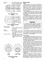
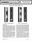
Impedance . . . . . . . . . . .8 ohms nominal (see Figure 1)
Frequency Response . .50 Hz to 15 kHz (see Figure 2)
Crossover Frequency . .2,000 Hz; high frequency: 18 dB/
octave rolloff
Sound Pressure
Level (SPL) . . . . . . . .EIA rating: 53 dB at 9.2m (30 ft)
from 1 milliwatt, equivalent to
102 dB at l m (3.3 ft) with 1watt input
Phasing (Polarity) . . . . .Positive voltage on phone jack
tip produces positive sound
pressure
High Frequency
Section . . . . . . . . . . . .120° or 60° (adjustable) radial
horn, with high-power driver
Low Frequency
Section . . . . . . . . . . . .15-inch woofer
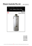
Horizontal Distribution ,120" or 60" (see Figure 3)
Vertical Distribution . . .90"
Directivity Factor
R, (Q) . . . . . . . . . . . . .6.6 at 2 kHz with 120" horn
angle; 10 with 60" horn angle
Environmental:
Operating
Temperature . . . . . - 7 to 43°C (20 to 110°F)
Storage
Temperature . . . . . - 29 to 71 "C ( - 20 to 160°F)
Printed i n U.S.A.
P a t e n t pending.
Connectors . . . . . . . . . .Two parallel-wired phone jacks
Cable . . . . . . . . . . . . . ..15m (50 ft), 18-gauge, rubberjacketed, with phone plugs
FREQUENCY IN HERTZ
TYPICAL IMPEDANCE CURVE
FIGURE 1
INSTALLATION
General
Maximum coverage for source-oriented installations is
generally obtained with the speakers on both sides of the
sound source and as far forward as possible. Each
speaker is tilted slightly either downward (for wall- or
ceiling-mounted units) or upward (for floor-standing
units). The angle of tilt (assuming a single speaker to
each side of the sound source) should be such that you
can look into the throat of the horn from the last rows
of the audience area.
If it is desirable to elevate the 701, adequate support
for heights up to about one meter (three feet) can usually
be obtained using a sturdy table or bench. The surface
must be capable of supporting the 26.4 kg (58 Ib) weight
of the speaker.
For greater elevations, the optional accessory Model
A112D Wall Mount Swivel Bracket is designed to support
the 701 for wall mounting only. It is important to note
that the 701 is not designed for mounting by simple
chains or cables attached to the cabinet top or sides. If
the 701 must be supported by chains or cables, encircle
or cradle it.
WARNING
TYPICAL FREQUENCY RESPONSE
FIGURE 2
Overall Dimensions
(including feet) . . . . .702 mm H x 584 mm W x 402
mm D (27-5/8 in. x 23 in. x
15-13/16 in.)
Weight . . . . . . . . . . . . . .26.4 kg (58 Ib)
Construction ........ .15.9 mm (5/8 in.) wood, black
vinyl covering, black fabric
grille, steel corner protectors,
plastic feet
Optional Accessories . .A701 C, Protective Slip-On Cover
with Cable Pocket, A112D,
Wall-Mount Swivel and Tilt
Bracket, A102A, 70-volt Transformer
LEGEND
LEGEND
...... 1000 HZ
TYPICAL POLAR PAlTERNS
FIGURE 3
It is extremely important that both the mounting
surface and the mounting hardware are adequate to
support the weight of the speaker. Inadequate support may result in a hazardous operating condition.
Whatever mounting means are employed, support
should be provided for a speaker static load of
105 kg (232 Ib). Actual weight of the speaker is
26.4 kg (58 Ib).
If two speakers are stacked for source-oriented installations, horn-to-horn mounting with horns angled apart
to cover separate areas will provide the best sound dispersion pattern. It is recommended that the horn angles
be set for 60" for stacked speakers.
Coverage Angles
The 701 Speaker System features a unique horn with
an adjustable horizontal dispersion pattern. The 120" or
60" angle adjustment provides unprecedented flexibility
that makes the 701 ideal in a wide variety of circumstances that previously required separate kinds of speakers to ensure adequate coverage.
Adjust the angle by turning the knob in the mouth of
the horn so that "60" or "120" is in the detented vertical
position. Use the 120" angle for coverage of short, wide
areas, in "short throw" applications. Use the 60" angle
for long, narrow areas, in "long throw" applications. The
60" position is also extremely useful when several speakers are employed to cover individual sectors of a very
large hall or outdoor stadium.
Judicious speaker/microphone placement and/or the
use of equalization or feedback filters in the sound system will often relieve acoustic feedback. In addition,
narrowing the horizontal dispersion angle from 120" to
60" can be useful in remedying high-frequency feedback
conditions when, for instance, speakers on stage have
dispersion patterns that overlap the pickup areas of open
microphones.
With the horn set at 60°, the energy in the high frequencies is concentrated in an area one half that of a
120" horn. This concentration causes an increase of
approximately 3 dB in the high-end response. The extra
high-end energy is extremely useful in providing maximum intelligibility for speech and singing voices and in
penetrating where acoustics are "dead" or where singers' voices must compete with loud amplified instruments
on stage.
70-Volt Line Operation
For operation from a 70-volt line, a transformer such
as the Shure Model A102A, providing power taps of 50,
25, 12, and 6 watts, should be used.
HOOKUP
Amplifiers
The 701 is designed for use with the Shure Model 700
Power Console and similar amplifiers having the following maximum power output capabilities.
Continuous Power To:
Voltage
16 ohms
8 ohms
4 ohms
34.6 Vrms
(55V peak)
75 watts
150 watts
300 watts
Speaker Wiring
Fifteen meters (50 ft) of cable is supplied with each
701 Speaker System. For convenient attachment, a
straight phone plug and a right-angle phone plug are
provided. Connect either end to the back of the speaker
and to the Power Console amplifier. The supplied cable
is 18 gauge (No. 18 AWG) and can be used for cable runs
of up to 15m (50 ft) between the speaker and the amplifier. If cable runs longer than 15m are required, use the
following table to determine the correct wire gauge.
Maximum
Distance From
Power Console
Amplifier
Wire Gauge
Recommended Cables
15m (50 ft)
AWG 18
30m (100 ft)
AWG 16
60m (200 ft)
AWG 14
Belden #8460, #8461,
#9470, #8542
Belden #8470, #8471,
# 8472
Belden #8473
Preferably, each speaker should be connected to a
separate amplifier output jack to minimize power losses
in the cable. Two parallel-wired jacks are provided on
the back of each 701 Speaker System. This allows connecting two speakers by connecting the first speaker to
the amplifier and the second speaker to the first. This
may be helpful in certain room shapes. However, when
speakers are connected in this manner, the next heavier
wire gauge is recommended between the amplifier and
the first speaker. Therefore, for two speakers connected
together where the first is at a distance of 30m (100 ft)
from the amplifier, use No. 14 AWG cable between the
amplifier and the first speaker; for two speakers where
the first is at 15m (50 ft), use No. 16 AWG cable between
the amplifier and the first speaker. When positioning the
speaker cables, place them where the audience, performers, or passers-by will not trip over them.
To avoid frequency response aberrations, poor coverage, and dead zones caused by improper speaker phasing in multiple speaker installations, all speakers must
be wired with the same polarity. The cables listed in the
chart above are color-coded to ensure that identical connections are used. Note that even common 18-gauge
lamp cord ("zip" cord) is phase-coded with ribs along
the outer jacket of one conductor.
The cable can be stored in the convenient snap-pocket
of the optional slip-on cover for the 701 speaker.
25-Volt Line Operation
The 701 can be operated from a 25-volt line without
the need for an accessory transformer. Note that the
speaker will draw 78 watts when connected to a constant-voltage, 25-volt line.
CHECKING SOUND COVERAGE
After the 701 speakers, Power Console amplifiers,
and other equipment have been installed and connected,
sound coverage can be checked as follows.
1. Apply a fairly constant-level signal to the system
(preferably low-level pink noise* or program material) and walk around the audience area. Listen for
a smooth, even output from the speakers, with minimal differences in volume and tone, and no "dead"
spots or phase distortion.
A. A dead spot-for audio purposes, where no direct
sound is heard, or where the sound level is appreciably lower-may
mean that the speakers
are not covering that area, or that the speaker
wires are connected out-of-phase. Proper phasing can be readily determined by checking the
connections on each speaker, but inadequate
coverage generally requires repositioning the
speakers. The dead area should be examined
carefully to determine that the problem can be
corrected without resorting to auxiliary speakers.
B. Phase distortion-a type of distortion distinguishable by being heard only in parts of the audience
area-can be due to overlapping areas of speaker coverage or sound reflecting off hard surfaces.
Re-aim the speakers or change the horn angle to
60" from 120" to eliminate this kind of distortion.
2. Use an Equalization Analyzer System such as the
Shure Model M615AS to supply and analyze a pink
noise signal. An octave equalizer like the ones found
on the Shure Model 700 PRO MASTERTM Power Console (or separate equalizers like the Shure Models
SR107 or M610) can be used to adjust the sound
system for optimum equalization and maximum gain
before feedback.
General
The 701 Speaker System can be modified for biamplified operation-where
separate power amplifiers are
used for high and low frequencies and are connected
individually to the high and low frequency speaker sections. The advantage of biamplification is the elimination
of high-frequency and intermodulation distortion caused
by high-level low-frequency signals. The separate power
amplifiers used in biamplification achieve the optimum
matching of power available and maximize acoustic output.
Modification of the 701 for Biamplified Operation
1. Remove the 15-inch woofer as described in the
Service Instructions. Take care not to break the
leads to the speaker terminals or damage the cone.
2. Cut the red jumper lead that connects the two jacks
on the panel inside the cabinet. Insulate both ends
of the red jumper lead.
3. Note to which jack the woofer is directly connected.
On the outside of the cabinet, mark this jack "LOW";
mark the other jack "HIGH".
4. Replace the woofer as described in the Service
Instructions.
Sine-wave signals delivering 150 watts to a speaker should be avoided
because they present a much greater average power than does pink noise
or program material. Consequently, when setting up or adjusting a sound
system with the 701 speaker, avoid the use of high-level, continuous-type
test signals.
Connections for Biamplified Operation
When the 701 has been modified for biamplified operation, each speaker section is designed to operate with
an amplifier capable of delivering 150 watts continuous
(34.6 Vrms, 55V peak) to an 8-ohm load. To biamplify, an
active crossover, such as the Shure Model SR106, is
required to separate the high and low frequencies. Set
the crossover frequency at 2600 Hz, and connect the
crossover high- and low-frequency outputs to separate
amplifiers, such as the A and B Power Amps of the Shure
Model 700 Power Console. Connect the speaker output
from the low-frequency amplifier to the 701 jack marked
"LOW"; connect the speaker output from the highfrequency amplifier to the jack marked "HIGH".
SERVICE INSTRUCTIONS
Diagnosing the Problem
1. Disconnect the speaker cables.
2. Using an ohmmeter, measure the resistance between
the tip and sleeve of either phone jack. The dc
resistance should be 5.5 to 6.5 ohms. A clicking
sound will be made by a "good" woofer when an
ohmmeter is connected or disconnected.
NOTE: This test checks only the woofer because
the crossover network is between the phone jacks
and the high-frequency driver.
3. For access to the high-frequency driver and crossover network, proceed as follows.
Note: This is most easily performed by supporting
the cabinet on its back on a bench with the head of
the large bolt in the upper center of the cabinet back
hanging over the edge.
A. Unscrew and remove the bolt from the upper
center of the cabinet back.
B. Pull the horn and driver assembly out until the
crossover network clears the front of the cabinet.
C. Disconnect the black lead that extends from the
crossover to the jack panel. This will permit the
driver to be partially removed from the cabinet.
Note that the crossover and jack panel are still
attached by a red lead. This lead has an insulated
in-line connector. Push back the insulated sleeve
and disconnect the terminals, completely freeing
the horn and driver from the cabinet.
4. Using an ohmmeter, measure the resistance between
the driver terminals. The dc resistance should be 5
to 7 ohms. A clicking sound will be made by a
"good" driver as described in step 2 above.
5. If the above tests do not locate the problem, apply
a small ac voltage from an oscillator and amplifier
to each speaker individually. Use approximately 4V,
50 Hz to 3 kHz for the 15-inch woofer, and approximately 2V, 500 Hz to 15 kHz for the high-frequency
driver. As the test signal frequency is varied, any
erratic buzzes or rattles indicate possible problems.
WARNING
Sound pressure levels generated by this test may
be damaging to your hearing. Aim speakers away
from listeners and toward sound-absorbent material
(curtains, blanket, etc.) Carefully adjust test signal
amplitude to avoid unnecessarily high sound pressure levels for prolonged periods.
6. To reassemble, connect the jack panel leads: black
lead to the crossover terminal with a black lead on
it (outside terminal); reconnect the red lamp lead
from the driver and the red lead from the jack panel.
Slide the sleeve over to insulate the connector.
7. With the crossover facing the top of the cabinet,
replace the driver and horn assembly by inserting
it in the cabinet and firmly tightening the bolt.
Replacing the 15-Inch Woofer or Gaining Access to the
Jack Panel
1. Remove the grille by pulling the two tabs at the top.
2. Remove the eight screws that hold the woofer in
place.
3. Pull the woofer forward out of the cabinet and disconnect the red and black leads from the woofer
terminals. The woofer is now free from the cabinet
and can be lifted out and removed. Take care not
to damage the cone nor to break the leads when
performing this operation.
4. Before replacing the woofer, connect the leads: red
lead to the coded terminal.
5. When reassembling, insert the woofer in the cabinet
and tighten the eight previously removed screws.
6. Press the grille back in place.
Replacing the High-Frequency Driver
1. Remove the horn, driver, and crossover network from
the cabinet as described in step 3 of the section
Diagnosing the Problem.
2. At the crossover, disconnect the black, white, and
red leads that come from the driver.
3. Unscrew the driver from the back of the horn.
NOTE: The driver diaphragm and coil (RKC157) and
the overload protection lamps (RKC166) can be replaced. Instructions for replacement are enclosed
with the replacement part kit.
4. When reassembling, screw the driver to the back
of the horn. The driver should be tightened by hand.
Do not use a wrench or other tools.
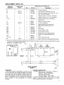
5. Connect the black and white driver leads and the
uninsulated red lamp lead to the crossover (see
Figure 4): black lead to the terminal with a black
lead on it (outside terminal); white lead to the terminal with the 9.4 F, capacitor soldered to its center
(other outside terminal); red lead to the center terminal (between the two outside terminals).
6. Reassemble in the cabinet as described in steps 6
and 7 of Diagnosing the Problem.
ACCESSORIES
The following optional accessories are available for
use with the 701 PRO MASTERTM Speaker System.
A701C Slip-On Protective Cover is a heavy vinyl cover
that provides protection for the speaker. Has cutouts for
the cabinet projections used as carrying handles.
Equipped with a snap-pocket for cable storage.
A112D Wall Mount Swivel Bracket permits 90" rotation
of the speaker about a horizontal axis, and 120" of
horizontal rotation when mounted on a vertical surface.
Heavy-duty steel construction.
A102A 70-Volt Transformer provides wattage taps of
50, 25, 12, and 6 watts for 70-volt distributed systems,
and impedance taps of 8 and 16 ohms. Mounts easily to
the back of a speaker or convenient surface.
REPLACEMENT PARTS LIST
Reference
Designation
Replacement Kit Consists Of:
Replacement
Kit No.*
Qty.
A1
-
-
90A2838
A2
RKC157
1
90A2636
High-Frequency Diaphragm and Coil
A3
RKC166
1
94A1483A
C1
-
50A71
Capacitor, Mylar, 4.7 pF, l o % , 250 WVdc**
C2
-
Overload Protection Kit (includes PL1, PL2
and mounting hardware)
Capacitor, Mylar, 9.4 pF, l o % , 250 WVdc**
-
-
50F71
J1, J2
90BA2600
Connector, Phone Jack, 2-Conductor,
Open Circuit
L1
-
-
95A647
Inductor, 0.5 mH, 0.4 ohms
LSI
RKCI 58
1
80B363
15-inch Loudspeaker
LS2
-
-
90A2650
MPI
-
-
High-Frequency Driver (See A2 for
Replacement Diaphragm and Coil)
90A2768
Grille
65A999A
Foot, Plastic
53A1656A
Corner Protector, Rear
-
53A1563B
Corner Protector, Front
65A1230A
-
-
Molded Horn, Top or Bottom Section
(Order 2 for Complete Molded Horn)
90B2767
Knob
-
95A932A
Lamp, Automotive 1156
RKC4
1
90C1373
Cable, 15.2m (50 ft), with Male Phone Plugs
MP2
MP3
MP4
MP5
MP6
PLI, PL2
W1
-
-
Part No.
Description
Crossover Network
* Parts listed as RKC Kits should be ordered by that kit number. Any orders received for piece parts where RKC Kit number
is shown will he s h.i .~ ~ eindRKC auantities.
*' Selected for low dissipation factor.
CROSSOVER NETWORK
JI
BLACK
RED
WHITE
PARALLEL
RED
INPUTS
-&Igq
n
J2
CIRCUIT DIAGRAM
FIGURE 4
GUARANTEE
This Shure product is guaranteed in normal use to be
free from electrical and mechanical defects for a period
of one year from date of purchase. Please retain proof
of purchase date. This guarantee includes all parts and
labor. This guarantee is in lieu of any and all other guarantees or warranties, express or implied, and there shall
be no recovery for any consequential or incidental
damages.
LS I
1404-1 1-2
SHIPPING INSTRUCTIONS
Carefully repack the unit and return it prepaid to:
Shure Brothers Incorporated
Attention: Service Department
1501 West Shure Drive
Arlington Heights, Illinois 60004
If outside the United States, return the unit to your
dealer or Authorized Shure Service Center for repair.
The unit will be returned to you prepaid.
5