1
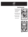
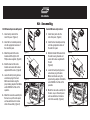
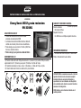
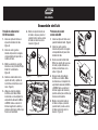
INSTALLATION INSTRUCTIONS FOR PART 99-3012G
APPLICATIONS
Chevy Sonic 2012-up
99-3012G
WIRING & ANTENNA CONNECTIONS (sold separately)
Wiring Harness:
• Interface included
Antenna Adapter:
• 40-EU55 multi-use antenna adapter
KIT FEATURES
• ISO DIN head unit provision with pocket
• DDIN head unit provisions
• Interface included retains factory OnStar, Bluetooth,
steering wheel controls, and all warning chimes
• Provides a 12-volt accessory power and VSS,
parking brake, and reverse signals
• Painted Gray to match factory finish
KIT COMPONENTS
• A) Radio trim panel • B) Radio brackets • C) Pocket • D) (4) #8 x 3/8” Phillips truss-head screws
• E) Panel clips • F) Interface • G) 16-pin harness • H) 4-pin to 4-pin resistor pad • I) Resistor
• J) 22-pin to 44-pin harness • K) Female 3.5mm connector w/ Brown and Brown/White Wires
A
B
G
C
D
H
I
E
J
TOOLS REQUIRED
• Panel removal tool • Phillips screwdriver
• Socket wrench
F
K
CAUTION: Metra recommends disconnecting the
negative battery terminal before beginning any
installation. All accessories, switches, and especially
air bag indicator lights must be plugged in
beforereconnecting the battery or cycling the ignition.
NOTE: Refer to the instructions included with the
aftermarket radio.
99-3012G
Dash Disassembly
1. Using a panel removal tool, unsnap
and remove the panel surrounding
the radio (vents above radio
included). (Figure A)
2. Unclip and remove the factory A/C
vents from the radio trim panel.
3. Remove four 7mm screws to
remove the radio. (Figure B)
Continue to kit assembly
(Figure A)
(Figure B)
99-3012G
Kit Assembly
ISO DIN head unit provision with pocket
Double DIN head unit provisions
1. Install factory vents into the
radio trim panel. (Figure A)
1. Install factory vents into the
radio trim panel. (Figure A)
2. Install the four included panel clips
onto the appropriate locations of
the radio trim panel.
2. Install the four included panel clips
onto the appropriate locations of
the radio trim panel.
3. Mount the pocket to the radio
brackets with the (4) #8 x 3/8”
Phillips screws supplied. (Figure B)
(Figure A)
4. Slide the head unit into radio
brackets and secure with screws
supplied with the radio. (Figure B)
5. Locate the factory wiring harness
and antenna plug in the dash.
Metra recommends using the
proper mating adapters from Metra
and/or AXXESS. Test the unit for
operation.
6. Mount the new radio assembly into
the dash, snap-in the radio panel,
and reassemble dash in reverse
order of disassembly. (Figure C)
(Figure B)
3. Slide the Double DIN head unit into
the radio housing brackets and
secure with screws supplied with
the unit.
(Figure B)
4. Locate the factory wiring harness
and antenna plug in the dash.
Metra recommends using the
proper mating adapters from Metra
and/or AXXESS. Test the unit for
operation.
(Figure A)
(Figure B)
5. Mount the new radio assembly into
the dash, snap-in the radio panel,
and reassemble dash in reverse
order of disassembly. (Figure C)
(Figure C)
(Figure C)
99-3012G
Axxess Interface
Installation
FEATURES
•
•
•
•
•
•
•
•
•
•
•
Provides accessory (12-volt 10-amp)
Retains R.A.P. (Retained Accessory Power)
Used in amplified or non-amplified systems
Retains all warning chimes
Provides NAV outputs (parking brake, reverse,
mute, and V.S.S.)
Built in ASWC (Steering Wheel Control Interface)
Retains OnStar/OE Bluetooth
Adjustable volume for chimes and OnStar
High level speaker input
Micro “B” USB updatable
Retains balance and fade
INTERFACE COMPONENTS
• 4-pin to 4-pin resistor pad harness • 16-pin with
stripped leads • 22-pin to 44-pin Camaro Harness
• 18-pin to 10-pin HVAC Harness • Female 3.5mm
connector with Brown and Brown/White wires • Resistor
TOOLS REQUIRED
• Cutting tool • Crimping tool • Tape • Connectors
(butt-connectors, bell caps, etc.)
Installing the Interface
From the 16-pin harness:
• Connect the Red wires to the ignition/accessory
wire of the aftermarket radio
• Connect the Orange/White wire to the
illumination wire of the aftermarket radio. If the
aftermarket radio has no illumination wire, tape off
the Orange/White wire.
• Connect the Blue/White wire to the amp turn on
wire of the aftermarket radio.
• Connect the Brown wire to the mute wire of the
aftermarket radio. If the aftermarket radio does not
have a Mute wire, tape up the Brown wire.
• Connect the White wire to the left front positive
speaker output of the aftermarket radio
• Connect the White/Black wire to the left front
negative speaker output of the aftermarket radio
• Connect the Gray wire to the right front positive
speaker output of the aftermarket radio
• Connect the Gray/Black wire to the right front
negative speaker output of the aftermarket radio
• The Violet wire is not used in the application
• The Violet/Black wire is not used in the application
• The Green wire is not used in the application
• The Green/Black wire is not used in this application.
The following wires are for the aftermarket radios that
have navigation built in:
• Connect the Light Green wire to the parking brake
wire of the aftermarket navigation radio.
• Connect the Blue/Pink wire to the VSS or speed
sense wire of the aftermarket navigation radio.
• Connect the Green/Purple wire to the reverse wire
of the aftermarket navigation radio.
From the 22-way harness:
• Connect the 3.5mm jack to your aftermarket radios
steering wheel control input (if equipped)
Note: If using an Eclipse, Kenwood, or select JVC
radios, use supplied female 3.5 adaptor.
For Kenwood and select JVC radios: Connect the
SWC wire (normally Blue/Yellow) to the Brown wire
of the ASWC. Isolate and tape the Brown/White wire,
it will not be used.
Some of the newer Kenwood radios will auto detect
as a JVC. If this is the case, you can use a 12k ohm
resistor (included) in line between the Blue/Yellow
and brown wire of the female 3.5mm jack during
programming only. Or you can manually set the
radio type which is in the radio programming section
of this manual.
For Eclipse: Connect the Eclipse SWC wires (normally
Axxess Interface Installation 99-3012G
Installing the Interface
Brown and Brown/Black) to the Brown and Brown/
White wires of the ASWC. Brown goes to Brown and
Brown/White goes to Brown/Black. Sometimes this is
reversed, so reverse the wires if needed.
For Metra OE radios: Connect the SWC Key 1
wire (Gray) to the Brown wire of the ASWC female
3.5mm adapter.
For all other radios, plug in the male 3.5mm
connector of the ASWC into the back of the
aftermarket radio, designated for an external SWC
control interface. Please refer to the aftermarket
radios manual if you are in doubt where the 3.5mm
connector of the ASWC goes.
The Black/Yellow wire will be discussed later on in
the instructions
From the 44-way harness:
• Connect the Black wire to the ground wire of the
aftermarket radio.
• Connect the RCA’s to the AUX in on the aftermarket
radio (if equipped).
Note: This will allow you to retain the 3.5 AUX JACK
in the console.
• Connect the Yellow wire to the 12-volt constant wire
of the aftermarket radio.
• If the vehicle is amplified disconnect the 4-pin
harness located between the 44-way and 22-way
connector and connect the supplied 4-pin to 4-pin
resistor pad.
Amplified vehicles:
• Connect the Violet wire to the right rear positive
wire of the aftermarket radio
• Connect the Violet/Black wire to the right rear
negative wire of the aftermarket radio
• Connect the Green wire to the left rear positive wire
of the aftermarket radio
• Connect the Green/Black wire to the left rear
negative wire of the aftermarket radio
Non-amplified vehicles:
• Cut the resistors from the Green, Green/black,
Purple, Purple/Black right below the heat shrink
• Connect the Violet wire to the right rear positive
wire of the aftermarket radio
• Connect the Violet/Black wire to the right rear
negative wire of the aftermarket radio
• Connect the Green wire to the left rear positive wire
of the aftermarket radio
• Connect the Green/Black wire to the left rear
negative wire of the aftermarket radio
The Pink wire is not used in this application.
Installing the Interface:
1. With all the connections completed, plug the 16 and
22 pin harnesses into the interface.
2. Plug the 44 pin GM harness into the vehicle side
harness, and plug the aftermarket radio harness into
the aftermarket radio.
3. Reconnect the negative battery terminal.
Programming:
• You must cycle the A/C fan speed all the way to high
and back to low when you first install the kit.
Note: Continue to the “Testing the Interface” section
if you do not have factory audio controls on the
steering wheel.
Programming the
Steering Wheel Controls
1. Turn on the ignition.
2. The SWC status LED on the interface will begin to
blink rapidly.
3. Tap volume up steering wheel control until the LED
stops blinking rapidly.
4. The LED will go off when it detects the car.
Axxess Interface Installation 99-3012G
Programming the Steering Wheel Controls
5. It will then will blink the LED the number
corresponding to the radio type.
6. After a few seconds, the LED will then blink the
number of times corresponding to the radio ID type.
Testing the Interface
With the vehicle battery re-connected, cycle the key
on and off once and back on. Turn the ignition on, and
then turn the aftermarket radio on. Push the OnStar
button, the radio should turn off (radio will mute if
mute wire is connected) and you should hear OnStar.
Push the OnStar cancel button and the radio should
come back on. Cycle the A/C fan speed all the way to
high and back to low when you first install the kit.
Chime Volume Adjustment
1) With car on, shut off car and leave keys in
ignition. Open the car door and leave it open.
Chimes will be heard.
2) Wait 10 seconds, then with a small screwdriver
adjust the potentiometer fully counterclockwise (all
the way left), then clockwise to raise chime level
and counterclockwise to lower the chime level.
3) When the volume is at the desired level, remove
the keys from the ignition. This will lock the chime
volume at its current level.
Audio Level Adjustment
1) Start your vehicle and turn on the radio having
audio playing.
2) Turn your aftermarket radio’s volume up ¾ of the way.
3) With a small screwdriver adjust the potentiometer
clockwise to raise the audio level and
counterclockwise to lower the audio level.
4) Once at desired level your audio adjustment
is complete.
OnStar Level Adjustment
1. To manually program the aftermarket radio, turn
on the ignition, press and hold the “Volume Down”
button on the steering wheel control until the LED
goes solid red, then release “Volume Down”.
2. Press the “Volume Up” the number of times
needed to program the radio type.
3. Here is the chart to show how many presses of the
“Volume Up” button is needed for which radio you
are trying to program:
1
2
3
4
5
6
Eclipse
Kenwood
Clarion “Type 1”
Sony/Dual
JVC
Pioneer/Jensen
7
8
9
10
11
Alpine
Visteon
Valor
Clarion “Type 2”
Metra OE
To adjust the OnStar volume level find the
Black/Yellow wire on the 16-pin harness. Push the
blue OnStar button, while the voice is speaking tap
the Black/Yellow wire to ground. Once the volume is
set it will stay at that volume until the Black/Yellow
wire is tapped to ground again. This can be set during
installation and then left alone. If user adjustment is
desired, the customer may also tap “Volume Up” or
down on the steering wheel (if equipped) to adjust the
OnStar level.
4. Press and hold the “Volume Down” button for 5
seconds to finish programming. The LED will then
go off.
To manually set the radio type:
If the LED flashes do not match the radio you have
connected, you must manually program the ASWC to
tell it what radio it is connected to.
5. After a few seconds, the LED will then blink the
number of times corresponding to the radio type.
This number should be the same number the user
has just pressed the “Volume Up” button.
Axxess Interface Installation 99-3012G
Remapping the SWC buttons
Let’s say you have the 99-3012G programmed to your
vehicle and your radio and you want to change the
button assignment for the steering wheel controls.
For instance you would like “Seek Up” to be “Mute”.
First a few notes:
• The 99-3012G must have detected the vehicle and
radio it is attached to before you can remap.
• You can only start the remapping of the steering
wheel controls process after 20-seconds of turning
the ignition key on. If you wait longer than the
30-seconds you will have to turn the ignition off
then back on again.
• Within the first 20-seconds if any button other then
“Volume Up” or “Volume Down” is pushed, the
remapping process will stop.
• If during the remapping process no button is pushed
for 30-seconds the remapping process is aborted
and the original settings are reset.
So let’s begin the remapping process:
1. Ideally having the 99-3012G visible is
recommended since you can see the LED
flashes to confirm button recognition.
2. Turning off the radio is recommended.
3. After 20-seconds of turning the ignition on,
press and hold down the “Volume Up” button for
at least 25-seconds.
4. The LED will light up solid red. Release “Volume
Up” and the LED will go out. “Volume Up” has now
been programmed.
5. Follow the list below in order however pushing
the steering wheel control button you want for the
function below. If you want to skip a command
press the “Volume Up” on the steering wheel, this
will tell the 99-3012G to skip the command and go
to the next one.
1
2.
3.
4
5
6
7
Volume Up
Volume Down
Seek Up/Next
Seek Down/Prev
Source/”Mode”
Mute
Preset Up
8
9
10
11
12
13
14
Preset Down
Power
Band
Play/Enter
PTT (Push To Talk)
On Hook
Off Hook
Note: Remember not all radios will have all these
commands. Please refer to the radios’ owners manual
for specific commands recognized by the radio. For
instance the next command to be mapped is the
“Volume Down” command. Let’s say you want the
“Mode” button on your steering wheel to be the
“Volume Down” command. Hold down the “Mode”
button till the LED lights up solid red, and then release
it. Now your “Mode” button on the steering wheel is
“Volume Down”.
6. After the last button is programmed on your
steering wheel (you do not have to go through the
whole list), hold down the “Volume Up” button for
at least 10 seconds then the LED will go out or
after the 18th button is programmed or skipped the
LED will go out and the remapping is completed.
If for any reason after remapping the steering
wheel controls you want to return to the original
steering wheel control settings, follow these steps:
Resetting or Forcing Auto Learn
1. Within the first 20-seconds of turning the
ignition on. Press and hold down the original
“Volume Up” button (not the “Volume Down”
button remapped) for at least 25-seconds.
2. The LED will blink rapidly.
3. Release the Volume Up button and wait until the
LED goes on solid.
4. After the LED goes off the original steering
wheel control settings will be restored.
INSTRUCCIONES DE INSTALACIÓN PARA LA PIEZA 99-3012G
APLICACIONES
Chevy Sonic 2012 y más recientes
99-3012G
CARACTERÍSTICAS DEL KIT
• Provisión de unidad central ISO DIN con cavidad
provisiones de unidad central DDIN
• La interfase incluida retiene OnStar de fábrica, Bluetooth,
controles en el volante y todos los tonos de advertencia
• Provee energía para accesorios de 12 voltios y VSS, freno
de mano y señales de reversa
• Pintura color gris para igualar el acabado de fábrica
COMPONENTES DEL KIT
• A) Panel de moldura del radio • B) Soportes del radio • C) Cavidad • D) (4) tornillos Phillips de cabeza
segmentada #8 x 3/8” • E) Ganchos para panel • F) Interfase • G) Arnés de 16 pins
• H) Cojinete de resistencia de 4 pins a 4 pins • I) Resistencia • J) Arnés de 22 pins a 44 pins
• K) Conector hembra de 3.5mm con cables marrón y marrón/blanco
A
B
G
C
H
D
E
F
I
J
K
CABLEADO Y CONEXIONES DE ANTENA
(se venden por separado)
Arnés de cableado:
• Se incluye interfase
Adaptador de antena:
• 40-EU55 de usos múltiples adaptador de antena
HERRAMIENTAS REquERIDAS
• Herramienta de remoción de panel • Destornillador
Phillips • Herramienta toma de corriente
PRECAUCIÓN: Metra recomienda desconectar el terminal
negativo de la batería antes de comenzar cualquier
instalación. Todos los accesorios, interruptores y,
especialmente, las luces indicadoras de airbag deben
estar enchufados antes de volver a conectar la batería o
comenzar el ciclo de ignición.
NOTA: Remítase a las instrucciones incluidas con el
radio de postventa.
99-3012G
Desmontaje del tablero
1. Utilizando una herramienta de
remoción de panel, suelte y retire
el panel que rodea el radio (se
incluyen las rejillas arriba del
radio). (Figura A)
2. Desenganche y quite las rejillas del
aire acondicionado de fábrica del
panel de moldura del radio.
3. Retire los cuatro tornillos de 7 mm
para retirar el chasís del radio.
(Figura B)
(Figura A)
Continuará al ensamble del kit
(Figura B)
99-3012G
Ensamble del kit
Provisión de unidad central
ISO DIN con bolsillo
1. Instale las rejillas de fábrica en
el panel de moldura del radio.
(Figura A)
6. Monte el conjunto del radio en
el tablero, coloque a presión el
panel del radio y vuelva a armar
el tablero al revés de como lo
desarmó. (Figura C)
2. Instale los cuatro ganchos
incluidos del panel en los lugares
correspondientes del panel de la
moldura del radio.
3. Monte la cavidad en los soportes
del radio con los (4) tornillos Phillips
#8 de 3/8” suministrados.
(Figura B)
4. Deslice la unidad central en los
soportes del radio y sujétela con
los tornillos suministrados con el
radio. (Figura B)
(Figura A)
5. Ubique el arnés del cableado
de fábrica en el tablero. Metra
recomienda usar el adaptador de
acoplamiento adecuado de Metra
o AXXESS. Vuelva a conectar el
terminal negativo de la batería y
pruebe la unidad para verificar que
funcione correctamente.
(Figura C)
(Figura B)
Provisiones de unidad
central doble DIN
1. Instale las rejillas de fábrica en el
panel de moldura del radio. (Figura A)
2. Instale los cuatro ganchos
incluidos del panel en los lugares
correspondientes del panel de la
moldura del radio.
3. Deslice la unidad central doble
DIN en los soportes de la carcasa
del radio y sujete utilizando los
tornillos suministrados con la
unidad. (Figura B)
4. Ubique el arnés del cableado
de fábrica en el tablero. Metra
recomienda usar el adaptador de
acoplamiento adecuado de Metra
o AXXESS. Vuelva a conectar el
terminal negativo de la batería y
pruebe la unidad para verificar que
funcione correctamente.
5. Monte el conjunto del radio en
el tablero, coloque a presión el
panel del radio y vuelva a armar
el tablero al revés de como lo
desarmó. (Figura C)
(Figura A)
(Figura B)
(Figura C)
99-3012G
Instalación de
la interfase Axxess
CARACTERÍSTICAS
• Proporciona accesorio (12 voltios 10 amperes)
• Retiene R.A.P. (Corriente de accesorio retenida)
• Se usa en sistemas amplificados o no amplificados
• Retiene todos los tonos de advertencia
• Proporciona salidas de NAV (freno de mano,
reversa, silencio y V.S.S.)
• ASWC integrado (interfase de control en volante)
• Retiene OnStar / Bluetooth de fabricante original
• Volumen ajustable para tonos y OnStar
• Entrada de bocina de alto nivel
• Actualizable a micro “B” USB
• Retiene el balance y la intensidad
COMPONENTES DE LA INTERfASE
• Arnés de cojinete de resistencia de 4 pins a 4 pins • 16
pins con conectores pelados • Arnés de 22 pins a 44 pins de
Camaro • Arnés de 18 pins a 10 pins • Conector hembra de
3.5mm con cables marrón y marrón/blanco • Resistor
HERRAMIENTAS REquERIDAS
• Cortador • Pelacables • Cinta • Conectores
(p. ej., conectores a tope, tapas acampanadas, etc.)
Instalación de la interfase
Desde el arnés de 16 pins:
• Conecte los cables Rojos al cable de ignición/accesorio del
radio de mercado secundario.
• Conecte el cable Anaranjado/Blanco al cable de
iluminación del radio de mercado secundario. Si el radio de
mercado secundario no tiene cable de iluminación, cubra
con cinta el cable Anaranjado/Blanco.
• Conecte el cable Azul/Blanco con el cable de encendido
del amplificador del radio de mercado secundario.
• Conecte el cable Marrón con el cable de silencio del radio
de mercado secundario. Si el radio de mercado secundario
no tiene un cable de silencio, encinte el cable Marrón.
• Conecte el cable Blanco con la salida de la bocina positiva
frontal izquierda del radio de mercado secundario.
• Conecte el cable Blanco/Negro con la salida de la bocina
negativa frontal izquierda del radio de mercado secundario.
• Conecte el cable Gris con la salida de la bocina positiva
frontal derecha del radio de mercado secundario.
• Conecte el cable Gris/Negro con la salida de la bocina
negativa frontal derecha del radio de mercado secundario.
• El cable Violeta no se utiliza en la aplicación.
• El cable Violeta/Negro no se utiliza en la aplicación.
• El cable Verde no se utiliza en la aplicación.
• El cable Verde/Negro no se utiliza en la aplicación.
Los siguientes cables son para radios de mercado secundario
que tienen navegación integrada:
• Conecte el cable verde claro con el cable del freno de
mano del radio de navegación de mercado secundario.
• Conecte el cable azul/rosa con el cable VSS o de
detección de velocidad del radio de navegación de
mercado secundario.
• Conecte el cable verde/morado al cable de reversa del
radio con navegación de mercado secundario.
Desde el arnés de 22 vías:
Conecte el conector de 3.5 mm a la entrada de control del
volante de su radio de mercado secundario (si cuenta con
dicho equipamiento).
Nota: Si usa un radio Eclipse, Kenwood o algunos radios
JVC, use el adaptador hembra de 3.5mm suministrado.
Para radios Kenwood y algunos JVC: Conecte el cable
SWC (normalmente Azul/Amarillo) al cable Marrón del
ASWC. Aísle y encinte el cable Marrón/Blanco, no se
utilizará.
Algunos de los radios Kenwood más nuevos se detectarán
automáticamente como JVC. Si este es el caso, puede
usar una resistencia de 12k ohmios (incluida) en línea
entre el cable azul/amarillo y marrón del conector hembra
de 3.5mm durante la programación únicamente. O puede
configurar manualmente el tipo de radio que está en la
sección de programación de este manual.
Para Eclipse: Conecte los cables SWC del Eclipse
Instalación de la interfase Axxess 99-3012G
Instalación de la interfase
(normalmente Marrón y Marrón/Negro) a los cables Marrón
y Marrón/Blanco del ASWC. Marrón va con Marrón y
Marrón/Blanco va con Marrón/Negro. En ocasiones esto es
al revés; invierta los cables si se necesita.
Para radios Metra OE: Conecte el cable
SWC Clave 1 (gris) al cable marrón del adaptador hembra
de 3.5mm de ASWC.
Para todos los demás radios, conecte el conector macho
de 3.5mm del ASWC en la parte posterior del radio de
mercado secundario, designada para una interfase de
control externo SWC. Consulte el manual del radio de
mercado secundario si tiene dudas acerca de dónde debe
ir el conector 3.5mm.
El cable Negro/Amarillo se explicará más adelante
en las instrucciones.
Desde el arnés de 44 vías:
• Conecte el cable Negro con el cable de conexión a tierra
del radio de mercado secundario.
• Conecte los conectores RCA a la entrada AUX del radio de
mercado secundario (si se incluye).
Nota: Esto le permitirá retener el conector AUX de 3.5mm
en la consola.
• Conecte el cable Amarillo al cable de corriente constante
de 12 voltios del radio de mercado secundario.
• Si el vehículo está amplificado, desconecte el arnés
de 4 pins localizado entre el conector de 44 vías y de 22
vías y conecte el cojinete suministrado de resistencia de 4
pins a 4 pins.
Vehículos amplificados:
• Conecte el cable Violeta al cable positivo posterior derecho
del radio de mercado secundario.
• Conecte el cable Violeta/negro al cable negativo posterior
derecho del radio de mercado secundario.
• Conecte el cable Verde al cable positivo posterior izquierdo
del radio de mercado secundario.
• Conecte el cable Verde/Negro al cable negativo posterior
izquierdo del radio de mercado secundario.
Vehículos no amplificados:
• Corte las resistencias de los cables Verde, Verde/
Negro, Morado, Morado/Negro justo debajo del
termoencogimiento.
• Conecte el cable Violeta al cable positivo posterior derecho
del radio de mercado secundario.
• Conecte el cable Violeta/Negro al cable negativo posterior
derecho del radio de mercado secundario.
• Conecte el cable Verde al cable positivo posterior izquierdo
del radio de mercado secundario.
• Conecte el cable Verde/Negro al cable negativo posterior
izquierdo del radio de mercado secundario.
El cable Rosa no se utiliza en esta aplicación.
Instalación de la interfase:
1. Cuando termine todas las conexiones, conecte los arneses
de 16 y 22 pins a la interfase.
2. Conecte el arnés GM de 44 pins en el arnés lateral
del vehículo y conecte el arnés del radio de mercado
secundario en el radio de mercado secundario.
3. Reconecte la terminal de la batería negativa.
Programación:
• Debe ciclar la velocidad del ventilador de aire
acondicionado totalmente hasta arriba y volver a bajarlo al
instalar el kit por primera vez.
Nota: Proceda a la sección de PRUEBAS DE INTERFASE si
no tiene controles de audio de fábrica en el volante.
Programación del
controles en volante
1. Encienda la ignición.
2. El foco LED de estado SWC de la interfase empezará a
parpadear rápidamente.
3. Toque el volumen del control en el volante hasta que el
foco LED deje de parpadear rápidamente.
4. El foco LED se apagará cuando detecte el automóvil.
5. Luego parpadeará el número de veces que corresponda
al tipo de radio.
Instalación de la interfase Axxess 99-3012G
Programación del controles en volante
6. Después de unos cuantos segundos, el foco LED
parpadeará la cantidad de veces correspondiente al
tipo de radio.
Ajuste del nivel de audio
Para probar la interfaz
Con la batería del vehículo reconectada, cicle la llave
encendiéndola y apagándola una vez y luego volviendo
a encenderla. Abra la llave y luego encienda el radio de
mercado secundario. Presione el botón OnStar, el radio
debe apagarse (el radio se quedará en silencio si el cable
de silencio está conectado) y usted debe escuchar a OnStar.
Presione el botón de cancelación de OnStar y el radio debe
volver a escucharse. Cicle la velocidad del ventilador de aire
acondicionado totalmente hasta arriba y volver a bajarlo al
instalar el kit por primera vez.
2) Aumente el volumen del radio de mercado secundario hasta
llegar a ¾ del máximo nivel.
Ajuste del volumen de los tonos
1) Con el vehículo encendido, apague el auto y deje las
llaves en la ignición. Abra la puerta del carro y déjela
abierta. Se escucharán tonos.
2) Espere 10 segundos, luego con un pequeño
destornillador, ajuste el potenciómetro por completo
hacia la izquierda (a la izquierda hasta topar), luego hacia
la derecha para subir el nivel de los tonos y hacia la
izquierda para bajar el nivel de los tonos.
3) Cuando el volumen esté en el nivel deseado, retire las
llaves de la ignición. Esto bloqueará el volumen de los
tonos en su nivel actual.
1) Arranque su vehículo y encienda el radio mientras
reproduce audio.
3) Con un pequeño destornillador, ajuste el potenciómetro
hacia la derecha para aumentar el nivel de audio y hacia
la izquierda para disminuir el nivel de audio.
4) Una vez que haya llegado al nivel deseado, su ajuste de
audio está completo.
Ajuste del nivel de OnStar
1. Para programar manualmente el radio de mercado
secundario, encienda la ignición, presione y mantenga
presionado el botón de bajar volumen en el control
del volante hasta que el foco LED se quede en rojo sin
parpadear, luego suelte el botón de aumentar volumen.
2. Presione el botón de aumentar volumen la cantidad de
veces necesarias para programar el tipo de radio.
3. Esta tabla muestra cuántas veces es necesario presionar
al botón de subir volumen para el radio que está tratando
de programar:
1
2
3
4
5
6
Eclipse
Kenwood
Clarion “Type 1”
Sony/Dual
JVC
Pioneer/Jensen
7
8
9
10
11
Alpine
Visteon
Valor
Clarion “Type 2”
Metra OE
Para ajustar el nivel del volumen de OnStar, busque el cable
negro/amarillo en el arnés de 16 pins. Presione el botón azul
de OnStar y mientras la voz esté hablando, toque el cable
negro/amarillo a tierra. Una vez configurado el volumen,
permanecerá a ese nivel hasta que el cable amarillo/negro
vuelva a tocarse a tierra. Esto puede ajustarse durante la
instalación y después ignorarse. Si se desea que el usuario
pueda hacer ajustes, el cliente también puede pulsar el
botón que sube o baja el volumen desde el volante (si está
equipado) para ajustar el nivel de OnStar.
4. Presione y mantenga presionado el botón de bajar
volumen durante 5 segundos para terminar la
programación. El foco LED se apagará.
Para configurar manualmente el tipo de radio:
Si el parpadeo del foco LED no corresponde al radio que
tiene conectado, debe programar manualmente el ASWC para
indicar a cuál radio está conectado.
5. Después de unos cuantos segundos, el foco LED parpadeará
la cantidad de veces correspondiente al tipo de radio.
Este número debe ser igual que el número de veces que
el usuario ha presionado el botón de aumentar volumen.
Instalación de la interfase Axxess 99-3012G
Reasignación de botones SWC
Digamos que tiene el 99-3010S programado
para su vehículo y su radio y ahora quiere cambiar la
asignación de los botones para los controles del volante.
Por ejemplo, le gustaría que el botón de buscar siguiente
funcionara como silencio.
Nota:
• El 99-3010S debe haber detectado el vehículo
y radio conectado antes de que se puedan remapear
los botones.
•
Solo podrá iniciar el proceso de remapeo de los controles
del volante 20 segundos después de abrir la llave de
la ignición. Si espera más de 30 segundos, tendrá que
apagar la ignición y volver a encenderla.
•
En los primeros 20 segundos, si se presiona cualquier
botón que no sea el de subir o bajar volumen, el proceso
de remapeo se detendrá.
•
Si durante el proceso de remapeo no se presiona ningún
botón durante 30 segundos, el proceso de remapeo se
aborta y se restablecen los ajustes originales.
Empecemos entonces el proceso de remapeo:
1. Idealmente se recomienda tener el 99-3010S visible,
puesto que se puede ver el parpadeo del foco LED para
confirmar el reconocimiento de los botones.
2. Se recomienda apagar el radio.
METRA ACCESSORIES
3. 20 segundos después de encender la ignición, presione y
mantenga presionado el botón de subir volumen durante
cuando menos 25 segundos.
4. El foco LED se iluminará en rojo sin parpadear. Suelte el
botón de aumentar volumen y el foco LED se apagará. Ya
quedó programado el botón que sube el volumen.
5. Siga la lista que aparece a continuación en orden pero
presionando el botón de control del volante que desee
para la función de abajo. Si quiere saltarse un comando,
presione el botón de aumentar volumen en el volante,
esto le dirá al 99-3010S que se salte el comando y pase
al siguiente.
1
2.
3.
4
5
6
7
Volume Up
Volume Down
Seek Up/Next
Seek Down/Prev
Source/”Mode”
Mute
Preset Up
8
9
10
11
12
13
14
Preset Down
Power
Band
Play/Enter
PTT (Push To Talk)
On Hook
Off Hook
Nota: Recuerde que no todos los radios tienen todos estos
comandos. Consulte el manual del propietario del radio
para los comandos específicos reconocidos por el radio. Por
ejemplo, el siguiente comando a mapear es el comando de
bajar volumen. Digamos que usted quiere que el botón Modo
de su volante sea el botón para bajar el volumen. Mantenga
presionado el botón Modo hasta que el foco LED se ilumine
en rojo sin parpadear, luego suéltelo. Ahora el botón de Modo
de su volante es el botón para bajar el volumen.
6. Después de programar el último botón en su volante (no
tiene que pasar por toda la lista), mantenga presionado
el botón de aumentar volumen durante al menos 10
segundos y el foco LED se apagará. Después de que
programe o se salte el botón número 18, el foco LED se
apagará y el remapeo habrá terminado.
Si por algún motivo después de remapear los controles
del volante quiere volver a los ajustes originales del
volante, siga estos pasos:
Cómo restablecer o forzar el aprendizaje
automático en el SWC
1. En los primeros 20 segundos después de encender
la ignición Presione y mantenga presionado el botón
original de aumento de volumen durante 25 segundos,
cuando menos.
2. El foco LED parpadeará rápidamente.
3. Suelte el botón de aumentar volumen y espere hasta
que el foco LED se encienda sin parpadear.
4. Después de que el foco LED se apague, los ajustes
originales del control del volante se restablecerán.
STEREO DASH KITS