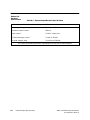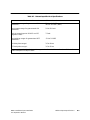
1
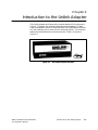
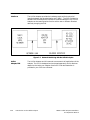
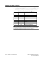
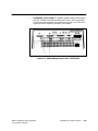
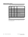
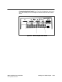
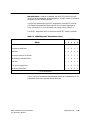
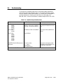
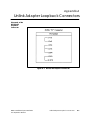
! "# $ % $&!'!' ""$( )* + Copyright 1994 by Siemens Industrial Automation, Inc. All Rights Reserved — Printed in USA Reproduction, transmission or use of this document or contents is not permitted without express consent of Siemens Industrial Automation, Inc. All rights, including rights created by patent grant or registration of a utility model or design, are reserved. Since Siemens Industrial Automation, Inc. does not possess full access to data concerning all of the uses and applications of customer’s products, we do not assume responsibility either for customer product design or for any infringements of patents or rights of others which may result from our assistance. Technical data is subject to change. We check the contents of every manual for accuracy at the time it is approved for printing; however, there may be undetected errors. Any errors found will be corrected in subsequent editions. Any suggestions for improvement are welcomed. MANUAL PUBLICATION HISTORY SIMATIC TIWAY 1 Unilink Adapter Installation and Operation Manual Order Manual Number: PPX:TIWAY–8106–2 Refer to this history in all correspondence and/or discussion about this manual. Event Date Description Original Issue Second Edition Errata 1 04/86 05/86 10/86 Third Edition Fourth Edition 02/87 04/94 Original Issue (2494092–0001) Second Edition (2494092–0002) Correct pages 4-17 – 4-20, 5-9 – 5-12, B-1 – B-2. (2599181–0001) Third Edition; incorporates Errata 1 (2494092–0003) Fourth Edition (2494092–0004) LIST OF EFFECTIVE PAGES Pages Cover/Copyright History/Effective Pages iii — v 1-1 — 1-2 2-1 — 2-2 3-1 — 3-6 4-1 — 4-28 5-1 — 5-17 A-1 — A-2 B-1 — B-3 Registration Description Fourth Edition Fourth Edition Fourth Edition Fourth Edition Fourth Edition Fourth Edition Fourth Edition Fourth Edition Fourth Edition Fourth Edition Fourth Edition Pages Description Contents Chapter 1 Manual Overview Organization . . . . . . . . . . . . . . . . . . . . . . . . . . . . . . . . . . . . . . . . . . . . . . . . . . . . . . . . . . . . . . . . . . . References . . . . . . . . . . . . . . . . . . . . . . . . . . . . . . . . . . . . . . . . . . . . . . . . . . . . . . . . . . . . . . . . . . . . . Technical Assistance . . . . . . . . . . . . . . . . . . . . . . . . . . . . . . . . . . . . . . . . . . . . . . . . . . . . . . . . . . . . Chapter 2 Introduction to the Unilink Adapter Interfaces . . . . . . . . . . . . . . . . . . . . . . . . . . . . . . . . . . . . . . . . . . . . . . . . . . . . . . . . . . . . . . . . . . . . . . Unilink Adapter/PIM . . . . . . . . . . . . . . . . . . . . . . . . . . . . . . . . . . . . . . . . . . . . . . . . . . . . . . . . . . . . . Chapter 3 Chapter 4 3-3 3-4 3-6 3-6 Installing Your Unilink Adapter Specifications and Certifications . . . . . . . . . . . . . . . . . . . . . . . . . . . . . . . . . . . . . . . . . . . . Installation Procedure . . . . . . . . . . . . . . . . . . . . . . . . . . . . . . . . . . . . . . . . . . . . . . . . . . . . . . Connector Wire Gauges – Summary . . . . . . . . . . . . . . . . . . . . . . . . . . . . . . . . . . . . . . . . Chapter 5 5.1 5.2 5.3 5.4 5.5 5.6 5.7 5.8 5.9 2-2 2-2 Hardware Description The Personality Interface Module . . . . . . . . . . . . . . . . . . . . . . . . . . . . . . . . . . . . . . . . . . . . . . . . Adapter Connectors . . . . . . . . . . . . . . . . . . . . . . . . . . . . . . . . . . . . . . . . . . . . . . . . . . . . . . . . . . . . External Loopback Connectors . . . . . . . . . . . . . . . . . . . . . . . . . . . . . . . . . . . . . . . . . . . . . . . . . . Mounting Brackets . . . . . . . . . . . . . . . . . . . . . . . . . . . . . . . . . . . . . . . . . . . . . . . . . . . . . . . . . . . . . . 4.1 4.2 4.3 1-1 1-2 1-2 4-2 4-3 4-28 Diagnostic Tests Status Display Indicators . . . . . . . . . . . . . . . . . . . . . . . . . . . . . . . . . . . . . . . . . . . . . . . . . . . . Diagnostic Tests: With or Without PIM . . . . . . . . . . . . . . . . . . . . . . . . . . . . . . . . . . . . . . . . Reset Switch . . . . . . . . . . . . . . . . . . . . . . . . . . . . . . . . . . . . . . . . . . . . . . . . . . . . . . . . . . . . . . . Dipswitches 1 and 2 . . . . . . . . . . . . . . . . . . . . . . . . . . . . . . . . . . . . . . . . . . . . . . . . . . . . . . . . Test Mode Selection . . . . . . . . . . . . . . . . . . . . . . . . . . . . . . . . . . . . . . . . . . . . . . . . . . . . . . . . LED Operation During Diagnostic Tests . . . . . . . . . . . . . . . . . . . . . . . . . . . . . . . . . . . . . . . User Diagnostic Tests . . . . . . . . . . . . . . . . . . . . . . . . . . . . . . . . . . . . . . . . . . . . . . . . . . . . . . . Reset Diagnostic Tests . . . . . . . . . . . . . . . . . . . . . . . . . . . . . . . . . . . . . . . . . . . . . . . . . . . . . . Troubleshooting . . . . . . . . . . . . . . . . . . . . . . . . . . . . . . . . . . . . . . . . . . . . . . . . . . . . . . . . . . . . 5-2 5-4 5-5 5-6 5-7 5-8 5-9 5-14 5-17 Appendix A Schematic of the RS-232/423 Loopback Connector . . . . . . . . . . . . . . . . . . . . . . . . . . . . . . . Schematic of the Mixed Media Loopback Connector . . . . . . . . . . . . . . . . . . . . . . . . . . . . Appendix B A-1 A-2 Unilink Adapter Specifications General Specifications and Certifications . . . . . . . . . . . . . . . . . . . . . . . . . . . . . . . . . . . . . . . . External I/O Electrical Specifications . . . . . . . . . . . . . . . . . . . . . . . . . . . . . . . . . . . . . . . . . . . . . Contents B-1 B-2 iii List of Figures Figure 2-1 The Unilink Adapter and PIM . . . . . . . . . . . . . . . . . . . . . . . . . . . . . . . . . . . . . . . . . . . . . . . . . Figure 2-2 Network Interfacing with the Unilink Adapter . . . . . . . . . . . . . . . . . . . . . . . . . . . . . . . . . 2-1 2-2 Figure 3-1 Figure 3-2 Figure 3-3 Figure 3-4 UNILINK Adapter and Hardware – PIM Installed . . . . . . . . . . . . . . . . . . . . . . . . . . . . . . . Unilink Adapter – Access Door Open . . . . . . . . . . . . . . . . . . . . . . . . . . . . . . . . . . . . . . . . . The PIM . . . . . . . . . . . . . . . . . . . . . . . . . . . . . . . . . . . . . . . . . . . . . . . . . . . . . . . . . . . . . . . . . . . . Unilink Adapter – Rear Panel . . . . . . . . . . . . . . . . . . . . . . . . . . . . . . . . . . . . . . . . . . . . . . . . 3-1 3-2 3-3 3-4 Figure 4-1 Figure 4-2 Figure 4-3 Figure 4-4 Figure 4-5 Figure 4-6 Figure 4-7 Figure 4-8 Figure 4-9 Figure 4-10 Figure 4-11 Figure 4-12 Figure 4-13 Figure 4-14 Unilink Adapter – Outside Dimensions . . . . . . . . . . . . . . . . . . . . . . . . . . . . . . . . . . . . . . . . Adapter Dimensions – Brackets Installed . . . . . . . . . . . . . . . . . . . . . . . . . . . . . . . . . . . . . Required Clearances for Proper Ventilation . . . . . . . . . . . . . . . . . . . . . . . . . . . . . . . . . . Rack-Mount Configuration . . . . . . . . . . . . . . . . . . . . . . . . . . . . . . . . . . . . . . . . . . . . . . . . . . Surface-Mount Configurations . . . . . . . . . . . . . . . . . . . . . . . . . . . . . . . . . . . . . . . . . . . . . . . Cable Installation . . . . . . . . . . . . . . . . . . . . . . . . . . . . . . . . . . . . . . . . . . . . . . . . . . . . . . . . . . . Unilink Adapter Ports 1 and 2 – Local Line . . . . . . . . . . . . . . . . . . . . . . . . . . . . . . . . . . . . Unilink Adapter Ports 1 and 2 – RS-232/423 . . . . . . . . . . . . . . . . . . . . . . . . . . . . . . . . . . . . Unilink Adapter Ports 3 and 4 . . . . . . . . . . . . . . . . . . . . . . . . . . . . . . . . . . . . . . . . . . . . . . . . Null Modem Cable . . . . . . . . . . . . . . . . . . . . . . . . . . . . . . . . . . . . . . . . . . . . . . . . . . . . . . . . External I/O Terminal . . . . . . . . . . . . . . . . . . . . . . . . . . . . . . . . . . . . . . . . . . . . . . . . . . . . . . . Connections to the External I/O Terminal . . . . . . . . . . . . . . . . . . . . . . . . . . . . . . . . . . . . Unilink Adapter Power Connector . . . . . . . . . . . . . . . . . . . . . . . . . . . . . . . . . . . . . . . . . . PIM Location . . . . . . . . . . . . . . . . . . . . . . . . . . . . . . . . . . . . . . . . . . . . . . . . . . . . . . . . . . . . . . 4-7 4-8 4-9 4-10 4-11 4-12 4-13 4-15 4-17 4-18 4-20 4-21 4-25 4-26 Figure 5-1 Figure 5-2 Figure 5-3 Figure 5-4 Figure 5-5 Figure 5-6 Adapter LEDs . . . . . . . . . . . . . . . . . . . . . . . . . . . . . . . . . . . . . . . . . . . . . . . . . . . . . . . . . . . . . . . ADAPTER GOOD LED . . . . . . . . . . . . . . . . . . . . . . . . . . . . . . . . . . . . . . . . . . . . . . . . . . . . . . . . LEDs 2 through 6 . . . . . . . . . . . . . . . . . . . . . . . . . . . . . . . . . . . . . . . . . . . . . . . . . . . . . . . . . . . . The RESET Switch . . . . . . . . . . . . . . . . . . . . . . . . . . . . . . . . . . . . . . . . . . . . . . . . . . . . . . . . . . . . Dipswitches 1 and 2 . . . . . . . . . . . . . . . . . . . . . . . . . . . . . . . . . . . . . . . . . . . . . . . . . . . . . . . . . Dipswitch 2, Position 10 . . . . . . . . . . . . . . . . . . . . . . . . . . . . . . . . . . . . . . . . . . . . . . . . . . . . . . 5-2 5-3 5-4 5-5 5-6 5-7 Figure A-1 RS–232/423 Loopback Connector . . . . . . . . . . . . . . . . . . . . . . . . . . . . . . . . . . . . . . . . . . . Figure A-2 Mixed Media Loopback Connector . . . . . . . . . . . . . . . . . . . . . . . . . . . . . . . . . . . . . . . . . A-1 A-2 iv Contents List of Tables Table 3-1 Factory-Supplied Loopback Connectors . . . . . . . . . . . . . . . . . . . . . . . . . . . . . . . . . . . . . . 3-6 Table 4-2 Table 4-3 Table 4-4 Table 4-5 Table 4-6 Table 4-7 RS-232-C D-Connector Pin Assignments/Ports 1 and 2 . . . . . . . . . . . . . . . . . . . . . . . . . . 9-Pin Connector Pin Assignments . . . . . . . . . . . . . . . . . . . . . . . . . . . . . . . . . . . . . . . . . . . . . External Output Electrical Specifications . . . . . . . . . . . . . . . . . . . . . . . . . . . . . . . . . . . . . . External Input Electrical Specifications . . . . . . . . . . . . . . . . . . . . . . . . . . . . . . . . . . . . . . . . Unilink Adapter Voltage Requirements . . . . . . . . . . . . . . . . . . . . . . . . . . . . . . . . . . . . . . . . Connector Wire Gauges . . . . . . . . . . . . . . . . . . . . . . . . . . . . . . . . . . . . . . . . . . . . . . . . . . . . . 4-16 4-19 4-22 4-23 4-24 4-28 Table 5-1 Table 5-2 Table 5-3 Table 5-4 Unilink Adapter Diagnostic Test Modes . . . . . . . . . . . . . . . . . . . . . . . . . . . . . . . . . . . . . . . . USER Diagnostic Tests and Error Codes . . . . . . . . . . . . . . . . . . . . . . . . . . . . . . . . . . . . . . . . RESET Diagnostic Tests and Error Codes . . . . . . . . . . . . . . . . . . . . . . . . . . . . . . . . . . . . . . . Possible Adapter Malfunctions . . . . . . . . . . . . . . . . . . . . . . . . . . . . . . . . . . . . . . . . . . . . . . . 5-7 5-12 5-15 5-17 Table B-1 External Output Electrical Specifications . . . . . . . . . . . . . . . . . . . . . . . . . . . . . . . . . . . . . . Table B-2 External Input Electrical Specifications . . . . . . . . . . . . . . . . . . . . . . . . . . . . . . . . . . . . . . . . B-2 B-3 Contents v Chapter 1 Manual Overview This manual contains the basic information you will need to install, test, and troubleshoot the Siemens Industrial Automation, Inc. Universal Network Adapter (called the SIMATIC “Unilink Adapter” or the “Adapter” throughout the remainder of this manual). Subjects covered include: Organization • Dimensions • Functions • Mounting configurations • Electrical specifications • Connector pin assignments • Built–in diagnostic tests • Troubleshooting This manual is organized as follows: • Chapter 2 – Introduction to the Unilink Adapter. This chapter contains an overview of the Adapter’s function as an interface to SIMATIC TIWAY I, the Siemens Industrial Automation, Inc. Local Area Network. The Adapter’s general capabilities are also listed. • Chapter 3 – Hardware Description. This chapter describes the Adapter hardware components, including the PIM, the Loop–back Connectors, Ports 1 through 4, the External I/O Terminal, and the AC Power Terminal. • Chapter 4 – Installing Your Unilink Adapter. This chapter describes the installation procedures for the Unilink Adapter, and also provides the information required to properly install cables, connectors,and terminals. • Chapter 5 – Diagnostic Tests. This chapter describes the diagnostic tests available to you, and lists test procedures and error codes as well. Also included is a table giving possible Adapter malfunctions and the corrective action recommended. TIWAY 1 Unilink Adapter Installation and Operation Manual Manual Overview 1-1 • Appendix A contains schematic diagrams of the Unilink Adapter Loopback Connectors. • Appendix B lists the Adapter Specifications. • Index References Additional information covering both the TIWAY I theory of operation and the capabilities of the Unilink Adapter for your specific application can be found in the SIMATIC TIWAY Systems Manual (PPX:TIWAY–8101–x) and the appropriate Personality Interface Module (PIM) User’s Manual. Technical Assistance If you have any questions regarding the installation and operation of this equipment, or if more information is desired, contact your Siemens Industrial Automation, Inc. distributor or sales agent. If you need assistance in contacting your distributor or sales office in the United States, call 800–964–4114. If additional technical assistance is needed, call Siemens Industrial Automation, Inc. Technical Services Group in Johnson City, Tennessee at 615–461–2522. 1-2 Manual Overview TIWAY 1 Unilink Adapter Installation and Operation Manual Chapter 2 Introduction to the Unilink Adapter The Unilink Adapter and Personality Interface Module (PIM) are shown in Figure 2-1. Together they provide a tailored interface between a TIWAY I Local Area Network and an RS-232/RS-422/RS-Unilink423 device (referred to in the remainder of this manual as the “attached device”). This interface enables the attached device to communicate over TIWAY I as shown in Figure 2-2. Figure 2-1 The Unilink Adapter and PIM TIWAY 1 Unilink Adapter Installation and Operation Manual Introduction to the Unilink Adapter 2-1 Interfaces The Unilink Adapter provides the hardware required for the physical interface between the attached device and TIWAY I. The PIM provides the software that customizes the interface to the attached device. Any Unilink Adapter can be reconfigured to function with a new or different attached device by changing the PIM. Figure 2-2 Network Interfacing with the Unilink Adapter Unilink Adapter/PIM 2-2 The Unilink Adapter and this manual are common to all applications of the Adapter. The PIM is developed and purchased separately, and its features depend on the tasks your Adapter must fulfill. PIM documentation is provided in your PIM User’s Manual. Introduction to the Unilink Adapter TIWAY 1 Unilink Adapter Installation and Operation Manual Chapter 3 Hardware Description The purpose of this chapter is to describe the following hardware components of the Unilink Adapter: 1. The metal case, door, brackets, and associated hardware. 2. The PIM. 3. The Adapter Connectors. 4. The Loopback Connectors. Figure 3-1 UNILINK Adapter and Hardware – PIM Installed TIWAY 1 Unilink Adapter Installation and Operation Manual Hardware Description 3-1 The Metal Case and Door The Unilink Adapter’s metal case provides bracket-attachment bolt holes for secure factory-floor installation. As shown in Figure 3-2, the Unilink Adapter’s hinged door provides access to six LEDs, the RESET Switch, the Dipswitches, and the Personality Interface Module (PIM). Both the PIM label and the ADAPTER GOOD LED are visible when the Adapter’s door is closed. The door and case are designed to ground you when you touch them, discharging static electricity before you handle any of the Adapter’s internal components. The door should be closed securely when not in use. Figure 3-2 Unilink Adapter – Access Door Open 3-2 Hardware Description TIWAY 1 Unilink Adapter Installation and Operation Manual The Personality Interface Module The Personality Interface Module (PIM) configures the Unilink Adapter to interface with the attached device, and is purchased separately. Figure 3-3 The PIM The PIM is easily removed and replaced when the Adapter’s door is open. The PIM’s label is visible at all times. TIWAY 1 Unilink Adapter Installation and Operation Manual Hardware Description 3-3 Adapter Connectors The following connectors are provided on the Adapter’s rear panel: 1. Four D-type connectors. 2. One External Input/Output (I/O) Connector. 3. One Power Connector. Figure 3-4 Unilink Adapter – Rear Panel 3-4 Hardware Description TIWAY 1 Unilink Adapter Installation and Operation Manual NOTE: Unilink Adapter PPX:500–7111 is shown in Figure 3-4. The rear panel on your Adapter may differ. Connector configurations by model number follow, and Chapter 4 has detailed information on all Adapter connectors. Ports 1 and 2. Adapter PPX:500–7111 and PPX:500–7113 are configured for use with the Siemens Industrial Automation, Inc. Local Line media on the TIWAY I LAN, and have two 9-pin D-type female connectors at Ports 1 and 2. Adapter PPX:500–7112 and PPX:500–7114 are configured for use with RS-232/423 network transmission media, and have two 25-pin D-type female connectors at Ports l and 2. Ports 3 and 4. Port 3 on all models has a 25-pin D-type female connector. Port 4 on all models has a 9-pin D-type female connector. External I/O Connector. This is a 5-terminal, low voltage, screw-type connector which can be used as an interface to an external signal or device. TIWAY 1 Unilink Adapter Installation and Operation Manual Hardware Description 3-5 AC Power Connector. This is a 3-terminal screw-type connector. ! WARNING External Loopback Connectors The AC power connector cover should always be replaced after field-wiring the Adapter AC power, and before power is energized. Loopback connectors are provided for use during the USER diagnostics described in Chapter 5. These connectors must be installed in order for your Adapter to successfully complete the diagnostic tests. Table 3-1 Factory-Supplied Loopback Connectors Loopback Connectors Provided Mounting Brackets 3-6 PPX# 9-Pin Connector (P/N 2494055-0001) 25-Pin Connector (P/N 2703834-0001) PPX:500-7111, PPX:500-7113 1 1 PPX:500-7112, PPX:500-7114 1 3 The L-shaped mounting brackets shown in Figure 3-1 are used to mount your Adapter in any one of several configurations described in Chapter 4. These brackets are attached to your Adapter using the screws which are supplied. Hardware Description TIWAY 1 Unilink Adapter Installation and Operation Manual Chapter 4 Installing Your Unilink Adapter This chapter provides the information necessary to properly install your Unilink Adapter. Included are the following: ! WARNING • the Adapter’s specifications and certifications. • hardware requirements. • hardware installation instructions. • Adapter dimensions. • required clearances for proper ventilation. • Adapter mounting configurations. • Local Line and RS-232-C cable installation guidelines. • suggested wire gauges. Do not apply AC power to the Unilink Adapter until you have completed all other installation procedures. TIWAY 1 Unilink Adapter Installation and Operation Manual Installing Your Unilink Adapter 4-1 4.1 Specifications and Certifications • Operating Temperature Range = 0 to 60° C (32 to 140° F) • Storage Temperature Range = –40 to 85° C (–40 to 185° F) • Humidity = 0 to 95% (non-condensing) • AC Line Voltage and Frequency (field-wired): PPX:111, PPX:7112: 88 – 132 VRMS, 47 to 63 Hz PPX:7113, PPX:7114: 140 – 264 VRMS, 47 to 63 Hz 4-2 • Power dissipation = 20 vA maximum • Agency approvals = UL Listed; FM Class I Div. 2 Approved • Vibration = NAVMAT T 9492 Installing Your Unilink Adapter TIWAY 1 Unilink Adapter Installation and Operation Manual 4.2 Installation Procedure The steps listed in this section should be followed when installing the Unilink Adapter. Some needed information is found in other chapters, which are referred to wherever necessary. NOTE: You should read this entire section before attempting to install your Unilink Adapter. The procedures given here assume that you have an operating TIWAY I Local Area Network. If you have questions regarding your TIWAY I network, please refer to your SIMATIC TIWAY Systems Manual (PPX:TIWAY–8101–x). TIWAY 1 Unilink Adapter Installation and Operation Manual Installing Your Unilink Adapter 4-3 Installation Procedure (continued) Adapter Installation – Overview. The steps listed in this paragraph summarize the Unilink Adapter installation procedures. Details of each step will be found in the paragraphs which follow this list. 1. Make certain you have all necessary Unilink Adapter hardware components for your Adapter model as listed in this section. 2. Install the Adapter in a secure place which is convenient to your TIWAY I network communications media and the attached device. 3. If you have not done so already, install any network cables and droplines necessary to connect Unilink Adapter Ports 1 through 4 to your equipment. 4. Wire in the connections to the External I/O Terminal, if this terminal is to be used in your application. 5. Install the PIM. 6. Field wire the AC power line in accordance with local electrical codes. 7. Replace the AC power terminal cover. 8. Apply AC power to the Adapter. 9. Execute USER Diagnostic Tests. 10. Execute RESET Diagnostic Tests. 11. Remove AC power from the Adapter. 12. Install the appropriate cables on Ports 1 through 4. ! 4-4 CAUTION Before re-applying power to the Adapter and its attached equipment, program the network computer(s) to operate the Unilink Adapter in accordance with the instructions in your PIM User Manual. Installing Your Unilink Adapter TIWAY 1 Unilink Adapter Installation and Operation Manual Procedures and references for each of the above steps are given in the paragraphs below. Hardware Components NOTE: If you are installing your own TIWAY I network cables, please refer to your SIMATIC TIWAY Systems Manual (PPX:TIWAY–8101–x) for additional information. The following hardware is required to properly install the Unilink Adapter: 1. The Unilink Adapter. 2. L-shaped mounting brackets and the 10-32 x .375 bracket screws (supplied with your Adapter). 3. Local Line or RS-232-C network cables with the appropriate “D”-type male connectors in place. Included with each Unilink Adapter PPX:500–7111 and PPX:500–7113 are two 9-pin D-type male connectors for use in constructing droplines from the TIWAY I Local Line. Local Line RS-232-C/423 PPX:500-7111* PPX:500-7112+ PPX:500-7113* PPX:500-7114+ *9-pin D-connectors included; +25-pin D-connectors not included 4. AC power connector cover (supplied with your Adapter). 5. Loopback connectors for USER Diagnostic Tests (supplied with your adapter). – Two loopback connectors are included with PPX:500–7111 and PPX:500–7113. – Four loopback connectors are included with PPX:500–7112 and PPX:500–7114. TIWAY 1 Unilink Adapter Installation and Operation Manual Installing Your Unilink Adapter 4-5 Installation Procedure (continued) 6. Two Siemens Industrial Automation, Inc. Tap Housings, Part No. 2702766–0001 (for Local Line installations only – supplied with your Adapter). 7. Mounting screws (user-supplied – .250 diameter). 8. RS-232-C cable for use with modems (both cable and modems are user-supplied). 9. AC power wiring up to 14 A.W.G. (user-supplied and field-wired). 10. Dust caps – installed on all Adapter connectors. ! CAUTION Dust caps should remain in place unless the connectors they cover are actually used. For example, if you do not have dual transmission media, the dust cover for the unused network port should NOT be removed. Mounting the Adapter. For maximum environmental protection, and to ensure extended trouble-free operation, Siemens Industrial Automation, Inc. recommends that you mount your Adapter in a standard NEMA enclosure. If this is not possible, the Adapter should be installed in a secure, stable, dry location free of corrosive elements, dirt, dust, ashes, and/or any other debris, particularly debris which may be a by-product of a manufacturing process. In general, a minimum distance of three feet should be maintained between the Unilink Adapter and any of the following: 4-6 1. Power lines carrying 440 volts or greater. 6. Induction furnaces and heaters. 2. Generators. 7. Rectifiers. 3. Electric motors. 8. All sources of microwave radiation. 4. Transformers. 9. Teletypes. 5. Electric welders. Installing Your Unilink Adapter TIWAY 1 Unilink Adapter Installation and Operation Manual • Adapter Dimensions Without Brackets. Adapter outside dimensions are given in Figure 4-1. Figure 4-1 Unilink Adapter – Outside Dimensions TIWAY 1 Unilink Adapter Installation and Operation Manual Installing Your Unilink Adapter 4-7 Installation Procedure (continued) • Adapter Dimensions – Brackets Installed. Center to center bolt hole dimensions (with mounting brackets installed) are given in Figure 4-2. Figure 4-2 Adapter Dimensions – Brackets Installed 4-8 Installing Your Unilink Adapter TIWAY 1 Unilink Adapter Installation and Operation Manual • Required Clearances. Figure 4-3 illustrates the clearances necessary for proper ventilation of the Adapter. Figure 4-3 Required Clearances for Proper Ventilation ! CAUTION Clearances shown will ensure proper ventilation only if all vents on your Adapter’s metal case are kept free of obstructions. TIWAY 1 Unilink Adapter Installation and Operation Manual Installing Your Unilink Adapter 4-9 Installation Procedure (continued) Mounting Configurations. Siemens Industrial Automation, Inc. recommends that you mount the Adapter in one of the configurations shown in Figure 4-4 or Figure 4-5 below. ! CAUTION There are several other ways to mount the Unilink Adapter; however, configurations other than those illustrated in this manual could adversely affect Adapter operation. Figure 4-4 Rack-Mount Configuration 4-10 Installing Your Unilink Adapter TIWAY 1 Unilink Adapter Installation and Operation Manual Figure 4-5 Surface-Mount Configurations TIWAY 1 Unilink Adapter Installation and Operation Manual Installing Your Unilink Adapter 4-11 Installation Procedure (continued) Cable Installation. Care should be taken when connecting cables to the Adapter ports to avoid bending pins or otherwise damaging the “D” connectors. After making certain all connectors are properly mated, secure them with their mounting screws (see Figure 4-6). Figure 4-6 Cable Installation 4-12 Installing Your Unilink Adapter TIWAY 1 Unilink Adapter Installation and Operation Manual Network Interface Ports 1 and 2. The Unilink Adapter Ports 1 and 2 (see Figure 4-7) are the TIWAY I network interface ports. They support either redundant Local Line transmission media (PPX:500-7111 and PPX:500–7113), or redundant RS-232/423 media (PPX:500–7112 and PPX:500–7114). Figure 4-7 Unilink Adapter Ports 1 and 2 – Local Line TIWAY 1 Unilink Adapter Installation and Operation Manual Installing Your Unilink Adapter 4-13 Installation Procedure (continued) • Local Line – Ports 1 and 2. The Local Line interface to TIWAY I is a female 9-pin “D” connector. Pin assignments are shown in Table 4-1. Table 4-1 Local Line Connector Pin Assignments Pin Name Description 1 Reserved 2 Reserved 3 Shield Cable shield and signal common 4 Reserved 5 Reserved 6 LLM+ Positive biased signal line 7 Reserved 8 Reserved 9 LLM– Negative biased signal line NOTE: The male ends of these two 9-pin connectors are included as part of the hardware supplied with the Adapter for use in constructing the Local Line drop cable. Suggested wire gauges are given in Table 4-7. 4-14 Installing Your Unilink Adapter TIWAY 1 Unilink Adapter Installation and Operation Manual • RS-232/423 – Ports 1 and 2. In Adapter models configured to support dual RS–232/423 transmission media, both Ports 1 and 2 have 25-pin D-type connectors installed. Figure 4-8 lists the Port 1 and 2 RS-232-C signals and their respective connector pin numbers. Figure 4-8 Unilink Adapter Ports 1 and 2 – RS-232/423 TIWAY 1 Unilink Adapter Installation and Operation Manual Installing Your Unilink Adapter 4-15 Installation Procedure (continued) Table 4-2 RS-232-C D-Connector Pin Assignments/Ports 1 and 2 Interchange Circuit Connector Pin No. C.C.I.T.T. AA 1 101 Protective ground AB 7 102 Signal Ground/Common Return BA 2 103 Transmitted Data BB 3 104 Receive Data CA 4 105 Request to Send CB 5 106 Clear to Send CC 6 107 Data Set Ready CD 20 108/2 CF 8 109 Receive Line Signal Detector DB 15 114 Transmitter Signal Element Timing DD 17 115 Receiver Signal Element Timing Description Data Terminal Ready NOTE: The male end of the 25-pin D-connector is not supplied with your Adapter. In the RS-232/423 configuration, the Unilink Adapter functions as Data Terminal Equipment (DTE). 4-16 Installing Your Unilink Adapter TIWAY 1 Unilink Adapter Installation and Operation Manual Communications Ports 3 and 4. Ports 3 and 4 are independent serial ports which are used by the Unilink Adapter to communicate with the attached device. Figure 4-9 Unilink Adapter Ports 3 and 4 TIWAY 1 Unilink Adapter Installation and Operation Manual Installing Your Unilink Adapter 4-17 Installation Procedure (continued) • Port 3. Port 3 is a general purpose serial port which implements a subset of RS-232-C control, data, and timing signals using RS-423 drivers and receivers. It utilizes a 25-pin D-connector. Port 3 signals and their respective connector pin numbers are given in Table 4-2. Port 3 is wired as Data Terminal Equipment (DTE). Some applications may require a port configured as Data Communications Equipment (DCE). Refer to your PIM User’s Manual to determine the appropriate configuration. For DCE configurations, use a null modem cable as shown in Figure 4-10. Figure 4-10 Null Modem Cable NOTE: The male end of the 25-pin D-connector is not supplied with the Adapter. In the DCE configuration, the Unilink Adapter will not provide synchronous timing signals at this port. 4-18 Installing Your Unilink Adapter TIWAY 1 Unilink Adapter Installation and Operation Manual • Port 4. Port 4 is an application-specific serial communications port which provides two media options in the same 9-pin connector. Please consult your PIM User’s Manual for your specific application. The transmission media options listed below are available at Port 4’s 9-pin connector. Connector pin assignments are listed in Table 4-3. 1. RS-422 Compatible 2. RS-423 Table 4-3 9-Pin Connector Pin Assignments Pin Signal Name Media 1 7 5 8 Transmit Data– Transmit Data+ Receive Data– Receive Data+ RS-422* RS-422* RS-422* RS-422* 2 3 9 6 4 Transmit Data Receive Data Request to Send Clear to Send Signal to Ground RS-423* RS-423* RS-423* RS-423* RS-423* * Since the Unilink Adapter will typically be operating in a noisy industrial environment line length not to exceed 50 feet is recommended. NOTE: The male end of the 9-pin D-connector for Port 4 is not supplied with your Adapter. TIWAY 1 Unilink Adapter Installation and Operation Manual Installing Your Unilink Adapter 4-19 Installation Procedure (continued) External Input/Output. Use of the External Input/Output (I/O) terminal will depend on your particular application. The PIM User Manual provides additional information concerning the use of the External Input/Output (1/O) terminal. The following paragraphs provide additional information concerning external 1/O connections. As an option, the Unilink Adapter provides through the 5-terminal External I/O Connector shown in Figure 4-11, one bit of input and one bit of output for external use. Please refer to your PIM User Manual for additional information. Figure 4-11 External I/O Terminal 4-20 Installing Your Unilink Adapter TIWAY 1 Unilink Adapter Installation and Operation Manual • External I/O Connector Pinout. The connections to the External I/O terminal should correspond to Figure 4-12. Suggested wire gauges are given in Table 4-7. NOTE: You must provide +20 to +30 VDC at pin 3 of the External I/O Terminal if you use the external output. You do not have to apply power if you use the input only. Figure 4-12 Connections to the External I/O Terminal TIWAY 1 Unilink Adapter Installation and Operation Manual Installing Your Unilink Adapter 4-21 Installation Procedure (continued) • The External Output. The Unilink Adapter optionally provides an output signal in the range of 0 to 30 volts, at a current range of 0 to 0.5 amps. Table 4-4 External Output Electrical Specifications All values are for worst-case conditions unless otherwise noted. User supply voltage range 20.0 to 30.0 VDC, Class 2 Maximum output current 500 mA Surge current 2.0 A for 1 ms OFF state leakage current 2.0 mA at 30 VDC ON state voltage drop 2.0 V Max. at 500 mA The output is internally protected against short circuits and reverse voltages. ! CAUTION 4-22 The I/O terminal snaps out of the Adapter’s rear panel, enabling you to connect wires without difficulty. Care should be taken when re-inserting the I/O terminal. Installing Your Unilink Adapter TIWAY 1 Unilink Adapter Installation and Operation Manual • ! CAUTION The External Input. The Unilink Adapter’s remote input terminal will accept incoming voltages as shown in Table 4-5. Voltages above those listed in Table 4-5 should not be applied to the External Input. Table 4-5 External Input Electrical Specifications All values are for worst-case conditions unless otherwise noted. Input voltage range for guaranteed ON conditions 20.0 to 40.0 VDC 20.0 to 36.0 VAC (RMS) Input current range for guaranteed ON conditions 5.0 to 15.0 mA 7.2 mA Typical current input at 24 VDC and 25 degrees Celsius –3.0 to 5.0 VDC ON delay time range* 3.5 to 10 ms OFF delay time range* 3.5 to 15 ms *Measured from the time the input changes to the time the information is available to the Unilink Adapter’s microprocessor. TIWAY 1 Unilink Adapter Installation and Operation Manual Installing Your Unilink Adapter 4-23 Installation Procedure (continued) Attaching the AC Power Cable. With power OFF, field wire the AC power cable to the Adapter. ! WARNING Always re-install the AC Power Connector Cover supplied with your Adapter. • Voltage requirements (by model number) are listed in Table 4-6. • An illustration of the AC power terminal is given in Figure 4-13. Table 4-6 Unilink Adapter Voltage Requirements 4-24 Model Number Network Port Input Voltage PPX:500-7111 PPX:500-7112 PPX:500-7113 PPX:500-7114 Dual Local Line Dual RS-232/423 Dual Local Line Dual RS-232/423 120 VAC 120 VAC 240 VAC 240 VAC Installing Your Unilink Adapter TIWAY 1 Unilink Adapter Installation and Operation Manual Figure 4-13 Unilink Adapter Power Connector NOTE: Suggested wire gauges are given in Table 4-7. PIM Handling Precautions. The PIM is a static-sensitive device, and should be handled with care to prevent the accidental destruction of its ROM by electrostatic discharge (ESD). 1. Handle the PIM as little as possible. 2. The PIM and persons handling the PIM should always be at the same ground potential. 3. The PIM should be stored and transported in its anti-static bag or in anti-static material. 4. Avoid touching the connectors which mate the PIM to the Unilink Adapter. Static discharge might damage the PIM’s internal components. TIWAY 1 Unilink Adapter Installation and Operation Manual Installing Your Unilink Adapter 4-25 Installation Procedure (continued) Installing/Removing the PIM ! WARNING AC Power to the Adapter should be disconnected any time a PIM is removed or replaced. The Adapter’s door should never be propped open; it should be held open with your free hand. Figure 4-14 PIM Location 4-26 • Installation. When installing the PIM, slide it onto the Adapter connector until it mates securely. Be careful to ensure correct vertical alignment of the connectors. The PIM shield should ensure proper horizontal alignment. • Removal. The PIM is removed by opening the Unilink Adapter’s hinged door with one hand, then grasping its plastic case firmly between thumb and forefinger of the other hand and pulling. Always secure the Adapter door when finished. Installing Your Unilink Adapter TIWAY 1 Unilink Adapter Installation and Operation Manual Initial Power-Up and Testing. Remove all cables attached to Ports 1 through 4 and proceed as follows: 1. Apply AC power. 2. Refer to Chapter 5 in this manual and execute USER diagnostics. NOTE: If the Adapter fails the USER diagnostics, refer to the Troubleshooting Section of Chapter 5 and proceed as suggested. 3. If the Adapter successfully completes USER Diagnostics, refer to Chapter 5 in this manual and execute RESET Diagnostics. NOTE: If your Adapter fails its RESET diagnostics, refer to the Troubleshooting Section of Chapter 5 in this manual, and proceed as suggested. 4. After successful completion of its diagnostic tests, your Unilink Adapter is ready for operation. Refer to your PIM User Manual for operational data relating to your specific application. TIWAY 1 Unilink Adapter Installation and Operation Manual Installing Your Unilink Adapter 4-27 4.3 Connector Wire Gauges – Summary The correct wire gauges for each connector and terminal on the Unilink Adapter are summarized in Table 4-7. Table 4-7 Connector Wire Gauges Connector/Terminal 25-Pin D-Type Connector 9-Pin D-Type Connector Screw-Terminal External I/O Screw-Terminal AC Power 4-28 Installing Your Unilink Adapter Wire Gauge 22 to 26 A.W.G. 22 to 26 A.W.G. Up to 14 A.W.G. Up to 14 A.W.G. TIWAY 1 Unilink Adapter Installation and Operation Manual Chapter 5 Diagnostic Tests The purpose of this chapter is to: • describe the functions of the Unilink Adapter’s switches and indicators. • provide complete diagnostic test procedures. The diagnostic tests described in this chapter verify the proper operation of: • the diagnostics Read Only Memory (ROM). • the Adapter’s microprocessor, including its Random Access Memory (RAM) and communications circuits. • the Adapter’s media boards, its power supply, watchdog timer, and external loopback circuits. • the ROM of the Personality Interface Module (PIM). A test failure generates an Error Code which defines the specific area in which the failure occurred. TIWAY 1 Unilink Adapter Installation and Operation Manual Diagnostic Tests 5-1 5.1 Status Display Indicators The SIMATIC Unilink Adapter has six status display indicators (LEDs). Only ADAPTER GOOD (LED number 1) is visible through the closed door. You must open the door to see the remaining five. Figure 5-1 Adapter LEDs During normal operation of the Unilink Adapter, the various functions of LEDs 2 through 6 are determined by the PIM. For a detailed discussion of these functions, please refer to your PIM User Manual. 5-2 Diagnostic Test TIWAY 1 Unilink Adapter Installation and Operation Manual When illuminated, the ADAPTER GOOD LED (see Figure 5-2) indicates that the Unilink Adapter is functioning normally. This LED is also used as an indicator during diagnostic testing and normal operation of your Adapter. For information regarding LEDs two through six during tests, please see Sections 5.7 and 5.8, which describe the LED functions during USER and RESET Diagnostic Tests. Figure 5-2 ADAPTER GOOD LED TIWAY 1 Unilink Adapter Installation and Operation Manual Diagnostic Tests 5-3 5.2 Diagnostic Tests: With or Without PIM Unilink Adapter diagnostic tests will execute with or without the PIM installed. However, when it is installed, the PIM executes tests in addition to those conducted by the Adapter alone. Please refer to your PIM User Manual for more information. If your PIM is not installed, the Unilink Adapter will test its own components. It will return Error Code 01000 indicating that the PIM is not installed, even if the Adapter passes all other tests. Errors are displayed on LEDs 2 through 6 (see Figure 5-3). For additional information, refer to Sections 5.7 and 5.8. Figure 5-3 LEDs 2 through 6 NOTE: One additional LED can be seen when the Unilink Adapter’s door is open. This LED (not shown in this manual) is located below and to the right of the RESET Switch. It is used only during Adapter manufacture and testing. 5-4 Diagnostic Test TIWAY 1 Unilink Adapter Installation and Operation Manual 5.3 Reset Switch The RESET Switch (see Figure 5-4) is accessible only when the Unilink Adapter’s door is open. ! WARNING Pressing this switch causes a hardware reset and stops all system operation. The Adapter enters a diagnostic test mode regardless of system activity in progress at the time. The test mode entered is either RESET Diagnostics or USER Diagnostics, depending on the configuration of Position 10 of Dipswitch 2. For additional information, please refer to Section 5.5 in this chapter, and to your PIM User Manual. Figure 5-4 The RESET Switch TIWAY 1 Unilink Adapter Installation and Operation Manual Diagnostic Tests 5-5 5.4 Dipswitches 1 and 2 Two ten-position dipswitches are accessible when the Unilink Adapter’s door is opened (see Figure 5-5). Figure 5-5 Dipswitches 1 and 2 The functions of each of the ten positions of Dipswitch 1, and the first nine positions of Dipswitch 2, are described in your PIM User Manual. Position 10 of Dipswitch 2 controls the diagnostic test mode entered at powerup of the Unilink Adapter, or upon entering RESET (pressing the RESET switch). The UP configuration of this switch places the Adapter in the USER diagnostic test mode at powerup or whenever the RESET Switch is pressed. When this switch is in the DOWN configuration, it places the Adapter in the RESET diagnostic test mode at powerup or whenever the RESET Switch is pressed. 5-6 Diagnostic Test TIWAY 1 Unilink Adapter Installation and Operation Manual 5.5 Test Mode Selection The two diagnostic test modes available to you are RESET and USER. The mode the Adapter will enter depends on the configuration of Dipswitch 2, Position 10 (see Table 5-1). Figure 5-6 Dipswitch 2, Position 10 Table 5-1 Unilink Adapter Diagnostic Test Modes Dipswitch 2 Position 10 Test Mode Entered at power-up/RESET PIM UP DOWN USER Test RESET Tests/Operations Mode Not Required* Not Required* *Adapter Diagnostics will run with or without the PIM installed. The Operations Mode is entered only when Position 10 of Dipswitch 2 is in the DOWN configuration. TIWAY 1 Unilink Adapter Installation and Operation Manual Diagnostic Tests 5-7 5.6 LED Operation During Diagnostic Tests In both test modes, the diagnostics software will switch ON LEDs 1 through 6 for visual inspection at the beginning of the tests. After 1 second, all LEDs will then be switched OFF until the diagnostics finish, or until an error is detected. If the Unilink Adapter passes all Unilink Adapter tests and your PIM is installed, the software in your PIM will run further tests. For a description of USER Diagnostics, see Section 5.7. For a description of RESET Diagnostics, see Section 5.8. 5-8 Diagnostic Test TIWAY 1 Unilink Adapter Installation and Operation Manual 5.7 User Diagnostic Tests Prior to initiating USER Diagnostics, you must physically disconnect all cables from Ports 1, 2, 3, and 4. Removing the cable from the External I/O Terminal is not required. NOTE: Failure to install loopback connectors, as discussed in the following paragraphs, will cause the Adapter to fail its diagnostics. The Unilink Adapter enters this test mode when 1. dipswitch 2, Position 10, is in the UP configuration, and 2. a RESET occurs. NOTE: A RESET occurs when you power up the Unilink Adapter, and each time you press the RESET Switch after power-up. RS-232 Loopback Connector. Siemens Industrial Automation, Inc. RS-232 25-pin Loopback Connecter (Part Number 2703834–0001) should be installed for external loopback tests of all RS-232/423 media ports. This includes Ports 1 and 2 on Unilink Adapter PPX:500–7112 and PPX:500–7114 and Port 3 on all models. These Loopback Connectors are provided with your Adapter and a connector schematic diagram is given in Appendix A. TIWAY 1 Unilink Adapter Installation and Operation Manual Diagnostic Tests 5-9 User Diagnostic Tests (continued) NOTE: Ports 1 and 2 of Unilink Adapter PPX:500–7111 and PPX:500–7113 (dual Local Line) do not require the installation of loopback connectors. Mixed Media Loopback Connector. Port 4 (the mixed media channel) must have a 9-pin Siemens Industrial Automation, Inc. Loopback Connector (Part Number 2494055–0001) installed for satisfactory completion of the USER diagnostic tests. This connector is provided with your Adapter and a connector schematic diagram is given in Appendix A. External I/O Terminal. You are not required to install a loopback connector on the External I/O terminal. NOTE: Executing the USER Diagnostics will turn OFF the External Output. To determine whether the external I/O circuits are tested for your application, please refer to your PIM User Manual. 5-10 Diagnostic Test TIWAY 1 Unilink Adapter Installation and Operation Manual Test Execution. During USER diagnostics, all tests listed in Table 5-2 are carried out, whether a PIM is installed or not (including external loopback tests on Ports 1 through 4). If your PIM is installed, it will conduct additional tests. Please refer to your PIM User’s Manual for details. The ADAPTER GOOD LED will flash two times each second upon completion of the USER Diagnostic Tests, regardless of whether an error was found. Diagnostics stop when the first error is encountered. No Errors. When the Unilink Adapter successfully completes USER Diagnostics, LEDs 2 through 6 will be extinguished, but the ADAPTER GOOD LED will flash two times each second. This indicates that the loopback connectors should now be removed and the cables re-installed on Ports 1 through 4. Error Indications. If an error is detected during USER diagnostics, the ADAPTER GOOD LED will flash, and the Error Code will be displayed on LEDs 2 through 6 inside the Adapter door. For a list of Error Codes, refer to Table 5-2. TIWAY 1 Unilink Adapter Installation and Operation Manual Diagnostic Tests 5-11 User Diagnostic Tests (continued) Table 5-2 USER Diagnostic Tests and Error Codes LED PATTERN ERROR L 2 3 4 5 6 No Errors 0 0 0 0 0 Diagnostics ROM Error 0 0 0 0 1 RAM Error 0 0 0 1 0 0 0 0 0 0 0 0 0 0 1 1 1 1 0 0 1 1 0 1 0 Communications Circuit Error 0 0 1 1 1 PIM Missing or PIM ROM Error 0 1 0 0 0 –5 V Power Supply Error 0 1 0 1 0 Watchdog Timer Error 0 1 0 1 1 External Loopback Errors Port 1 External Loopback Port 2 External Loopback Port 3 External Loopback Port 4 External Loopback X X X X L = Loopback Connector Required 1 = LED Illuminated If your PIM is not installed and the Adapter passes all its diagnostics, Error Code 01000 (PIM Not Installed) will be returned. Returning the Unilink Adapter to an Operational State. At the completion of USER Diagnostics, the Unilink Adapter will enter a non-functional state regardless of whether it has passed or failed. 5-12 Diagnostic Test TIWAY 1 Unilink Adapter Installation and Operation Manual To return the Adapter to an operating state, follow the procedure outlined below. 1. Remove all loopback connectors installed on Ports 1, 2, 3, and 4. 2. Install the cables you removed at the beginning of the USER diagnostic test procedure. 3. Reconfigure Position 10 of Dipswitch 2 by moving the switch lever to DOWN. NOTE: Install the PIM (if it is not already installed). 4. Press the RESET Switch. At this point, the Unilink Adapter will run the RESET diagnostic tests as outlined in Paragraph 5.8. If no failure occurs and your PIM is installed, the operation of your Adapter will be turned over to the software in your PIM’s Read Only Memory. NOTE: At the completion of the RESET diagnostics, the ADAPTER GOOD LED flashes only if a failure occurs (see Section 5.8). TIWAY 1 Unilink Adapter Installation and Operation Manual Diagnostic Tests 5-13 5.8 Reset Diagnostic Tests The Unilink Adapter enters this test mode when: 1. Dipswitch 2, Position 10, is in the DOWN configuration, and 2. a RESET occurs. NOTE: RESET diagnostics will execute with or without cables installed on Ports 1 through 4. A reset occurs when you power up the Unilink Adapter, and each time you press the RESET Switch after powerup. During RESET diagnostics, all tests listed in Table 5-3 are carried out. Your PIM does not have to be installed for the RESET diagnostics to run. However, if the PIM is installed, it will conduct tests in addition to those conducted by the Adapter itself. Please refer to your PIM User’s Manual for details. If an error is found, the PIM will instruct the Adapter to display the appropriate Error Code on LEDs 2 through 6. For a list of the RESET Diagnostic Error Codes, refer to Table 5-3. 5-14 Diagnostic Test TIWAY 1 Unilink Adapter Installation and Operation Manual Error Indications. If no error is detected, the ADAPTER GOOD LED will illuminate at the completion of the diagnostics, and will remain illuminated. All other LEDs will be extinguished. If a failure is detected during RESET diagnostics, the ADAPTER GOOD LED flashes two times each second, and an Error Code is displayed on LEDs 2 through 6. For a list of these Error Codes, refer to Table 5-3. The RESET diagnostics will run each time the RESET switch is pressed. Table 5-3 RESET Diagnostic Tests and Error Codes LED PATTERN ERROR 2 3 4 5 6 No Errors 0 0 0 0 0 Diagnostics ROM Error 0 0 0 0 1 RAM Error 0 0 0 1 0 Communications Circuit Error 0 0 1 1 1 PIM Missing or PIM ROM Error 0 1 0 0 0 CPU Error 0 1 0 0 1 –5 V Power Supply Error 0 1 0 1 0 Watchdog Timer Error 0 1 0 1 1 1 = LED Illuminated If your PIM is not installed and the Adapter passes all its diagnostics. Error Code 01000 (PIM Not Installed) will be returned. TIWAY 1 Unilink Adapter Installation and Operation Manual Diagnostic Tests 5-15 Reset Diagnostic Tests (continued) Returning the Unilink Adapter to an Operational State. If no errors are found during the RESET Diagnostics, the Unilink Adapter will, upon completion of all tests, automatically pass control of its operation to the PIM. NOTE: Position 10 of Dipswitch 2 must be in the DOWN configuration for normal Adapter operation, and the PIM must be installed. 5-16 Diagnostic Test TIWAY 1 Unilink Adapter Installation and Operation Manual 5.9 Troubleshooting In the event of an Adapter malfunction, the following data should be of value when performing diagnostic tests. If you require assistance, please call your Siemens Industrial Automation, Inc. distributor or sales agent. If you need assistance in locating your distributor or sales agent, call 800–964–4114. If technical assistance is needed, telephone 615–461–2522. Table 5-4 Possible Adapter Malfunctions Symptom Possible Cause Action Error Codes 00011 00100 00101 00110 Error Code 01000 Loopback Connector not installed; improperly installed; or wrong connector installed. Check all loopback connectors; adjust or repair as necessary. Error Codes 00001 00010 00111 01001 01010 01011 Board failure.* ADAPTER GOOD LED does not illuminate. No input power; or LED/Adapter CPU malfunction.* Unit failure or PIM not installed. Check your PIM; install if necessary. Verify that user input power falls within specifications and is properly connected. *Call Siemens Industrial Automation, Inc. for additional information. TIWAY 1 Unilink Adapter Installation and Operation Manual Diagnostic Tests 5-17 Appendix A Unilink Adapter Loopback Connectors Schematic of the RS-232/423 Loopback Connector Figure A-1 RS–232/423 Loopback Connector TIWAY 1 Unilink Adapter Installation and Operation Manual Unilink Adapter Loopback Connectors A-1 Schematic of the Mixed Media Loopback Connector Figure A-2 Mixed Media Loopback Connector A-2 Unilink Adapter Loopback Connectors TIWAY 1 Unilink Adapter Installation and Operation Manual Appendix B Unilink Adapter Specifications General Specifications and Certifications • Operating Temperature Range = 0 to 60 degrees C (32 to 140 degrees F) • Storage Temperature Range = –0 to 85 degrees C (–40 to 185 degrees F) • Humidity = 0 to 95% (non–condensing) • AC Line Voltage and Frequency (field–wired): 7111, 7112: 88 – 132 VRMS, 47 to 63 Hz 7113, 7114:140 – 264 VRMS, 47 to 63 Hz • Power dissipation = 20 VA maximum • Agency Approvals = UL Listed; FM Class I Div. 2 Approved • Vibration = NAVMAT T 9492 TIWAY 1 Unilink Adapter Installation and Operation Manual Unilink Adapter Specifications B-1 External I/O Electrical Specifications Table B-1 External Output Electrical Specifications All values are for worst-case conditions unless otherwise noted. User supply voltage range 20.0 to 30.0 VDC, Class 2 Maximum output current 500 mA Surge current 2.0 A for 1 msecond OFF state leakage current 2.0 mA at 30 VDC ON state voltage drop 2.0 V Max. at 500 mA The output is internally protected against short circuits and reverse voltages. B-2 Unilink Adapter Specifications TIWAY 1 Unilink Adapter Installation and Operation Manual Table B-2 External Input Electrical Specifications All values are for worst-case conditions unless otherwise noted. Input voltage range for guaranteed ON conditions 20.0 to 40.0 VDC 20.0 to 36.0 VAC (RMS) Input current range for guaranteed ON conditions 5.0 to 15.0 mA Typical current input at 24 VDC and 25 degrees Celsius 7.2 mA Input voltage range for guaranteed OFF conditions –3.0 to 5.0 VDC ON delay time range* 3.5 to 10 ms OFF delay time range* 3.5 to 15 ms *Measured from the time the input changes to the time the information is available to the Unilink Adapter’s microprocessor. TIWAY 1 Unilink Adapter Installation and Operation Manual Unilink Adapter Specifications B-3 Customer Registration We would like to know what you think about our user manuals so that we can serve you better. How would you rate the quality of our manuals? Excellent Good Fair Poor Accuracy Organization Clarity Completeness Overall design Size Index Would you be interested in giving us more detailed comments about our manuals? Yes! Please send me a questionnaire. No. Thanks anyway. Your Name: Title: Telephone Number: ( ) Company Name: Company Address: Manual Name: SIMATIC TIWAY 1 Unilink Adapter Installation and Operation Manual Assembly Number: 2587871–0024 Order Number: PPX: TIWAY–8106–2 Edition: Date: Fourth 04/94 FOLD NO POSTAGE NECESSARY IF MAILED IN THE UNITED STATES BUSINESS REPLY MAIL FIRST CLASS PERMIT NO.3 JOHNSON CITY, TN POSTAGE WILL BE PAID BY ADDRESSEE ATTN: Technical Communications M/S 3519 SIEMENS INDUSTRIAL AUTOMATION INC. 3000 BILL GARLAND RD P O BOX 1255 JOHNSON CITY TN 37605–1255 FOLD