1
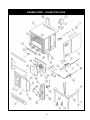
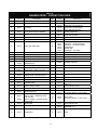
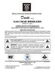
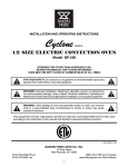
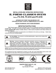
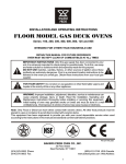
INSTALLATION AND OPERATION MAINTENANCE
CONVECTION OVEN
OWNER’S MANUAL
Models: BPCV-1, BPCV-1-1W, BPCV-1-2W, BPCV-2, BPCV-2-1W & BPCV-2-2W
All equipments manufactured by Bakers Pride Oven Co. Inc. for use with the type of gas specified on
the rating plate and for installation will be in accordance with National Fuel Gas Code ANSI Z223.1
(latest edition)
FOR YOUR SAFETY: Do not store or use gasoline or other flammable vapors or
liquids in the vicinity of this or any other appliance.
WARNING: Improper installation, adjustment, alteration, service or maintenance
can cause property damage, injury or death. Read the installation, operating and
maintenance instructions thoroughly before installing or servicing this equipment.
Instructions to be followed in the event the user smells gas must be posted in a prominent location in
the kitchen area. This information shall be obtained from the local gas supplier.
PLEASE RETAIN THIS MANUAL FOR FUTURE REFERENCES.
P/N 340410 05/11
BAKERS PRIDE OVEN CO. INC.,
2205 South Standard Avenue
Santa Ana, CA 92707
(714) 424-9380 Phone
(714) 424-9385 Fax
www.bakerspride.com Web address
1
TABLE OF CONTENTS
Installation Instructions .............................................................................................................................2
Operating Instructions...............................................................................................................................3
Cleaning and Maintenance ..................................................................................................................... 8
Exploded View ........................................................................................................................................10
Parts List .................................................................................................................................................11
Warranty ................................................................................................................................................13
IMPORTANT
Safe and satisfactory operation of your equipment depends to a great extent on its proper installation.
Installation must conform with local codes or in the absence of local codes, the National Fuel Gas
Code, ANSI 2223.1 (latest edition.). In Canada, installation should conform to installation codes for gas
burning appliances and equipment standard CAN1-B149.1 (Natural. gas) or CAN1-B149.2 (Propane
gas).
Electrical wiring from the Electric Meter, main control box or service outlet to appliance must be
electrically grounded in accordance with local codes or in the absence service of local codes with the
National Electrical Codes ANSI/NFPA 70 - current. In Canada, conform with Canadian Electrical
Code CSA-C22.1
INSTALLATION INSTRUCTIONS
• Installation of the equipment should be performed by qualified, certified, licensed and /or authorized
personnel who are familiar and experienced with local installation codes.
• Operation of the equipment should be performed by qualified or authorized personnel who have
read this manual and are familiar with the functions of the equipment.
• Service of the equipment should be performed by qualified personnel who are knowledgeable with
Bakers pride Cooking Equipments.
SHIPPING DAMAGE CLAIM PROCEDURE
The equipment is inspected and crated carefully by skilled personnel before leaving our factory. The
transportation company assumes full responsibility for safe delivery upon acceptance of this
equipment. If shipment arrives damaged:1. Visible loss or damage: Note on freight bill or express delivery and signed by person making
delivery.
2. File claim for damages immediately: Regardless of extent of damages.
3. Concealed loss or damage: If damage is noticed after unpacking, notify Transportation
Company immediately and file “Concealed Damage” claim with the transportation carrier. This
should be done within fifteen (15) days from the date delivery and receipt of goods. Retain
container for inspection.
2
GENERAL
1. A manual gas shut-off valve must be installed in the gas supply (service) line ahead of the appliance
and gas pressure regulator for safety and ease in servicing.
2. The gas pressure regulator supplied must be installed on the appliance prior to connecting the
equipment to the gas line. Failure to install a regulator could be potentially hazardous and will void
the appliance warranty.
3. The appliance and its individual shut off valve must be disconnected from the gas supply piping
system during any pressure testing of that system at test pressures in excess of ½ psi (3.45kpa).
4. The appliance must be Isolated from gas supply piping system, by closing its individual manual shut
off valve during any pressure testing of the gas supply piping system at test pressures equal to or
less than ½ psi (3.45kpa).
5. To perform maintenance and repairs of the appliance, please contact the factory, the factory
representative, or the nearest authorized local service company.
OPERATING INSTRUCTIONS
RATING PLATE
The rating plate is located in front of the range below the oven section. Information on this plate
includes the model, serial number, BTU / hour input of the burners, operating gas pressure in inches
WC, and whether the appliance is orificed for natural or propane gas. Pilot lighting instructions (ovens
only) are also located in the same area.
BAKERS PRIDE COOKING APPLIANCES MUST BE CONNECTED ONLY TO THE
TYPE OF GAS IDENTIFIED ON THE RATING PLATE
CLEARANCES
The appliance area must be kept free and clear of all combustibles. This unit is design-certified for the
following installations only:
The clearances from combustible and non combustible construction are as follows:
Back
Sides
Combustible
6"
6"
Non combustible
0
0
DO NOT MOUNT oven on a curb base. Use legs/casters provided. Adequate air space at the bottom
and rear of the unit must be provided for proper venting of blower motor.
ASSEMBLY
DO NOT USE door to lift or move oven!!! All ovens must be installed on leg assembly or casters
shipped with the unit
The leg/stand assembly parts or casters are shipped separately.
3
SINGLE OVEN
Assemble the leg/stand assembly as follows:
1. Remove legs from package.
2. Secure top frame parts to the legs with bolts provided (long angle - front & back. Short angle sides).
3. Place the oven on top of leg/stand assembly. Match holes on the frame with oven bottom base.
Fasten with bolts provided
If provided with optional bottom shelf and rack support: (Ref. Figure 1)
a. Screw the bottom shelf to the legs.
b. Screw rack guide support angles to bottom shelf & top leg frame.
DOUBLE OVEN
6" leg assembly is provided.
1. Match holes on the legs with oven bottom base and screw with bolts provided.
2. Set top oven on top of bottom oven.
3. Bolts down at rear and front as shown in Figure 2. Remove top kick plate to access screwing the
front bolts.
4. Assemble bottom flue extension as shown in Figure 2.
4
CASTER INSTALLATION
If caters are provided, match holes on the caster with holes on the oven bottom base and fasten with
bolts provided.
NOTE: Front casters are locking type.
LEVELLING
A carpenter’s spirit level should be used and placed on the oven’s center baking rack and or across the
range top and the unit leveled from front to back and side to side. If it is not level, cakes, casseroles and
any other liquid or semi liquid batter will not bake evenly, burner combustion may be erratic, and the
unit will not function efficiently.
If the floor is smooth and level, the appliance may be further leveled with adjustment in the foot of the
leg. Units with castors require adjustment with shims. A unit will probably not return to the same position
after being moved, requiring relevelling after each and every move.
AIR SUPPLY & VENTILATION
The area in front of, around and above the appliance must be kept clear to avoid any obstruction of the
flow of combustion and ventilation air. Adequate clearance must be maintained around the appliance for
servicing and proper operation.
5
Means must be provided for any commercial, heavy duty cooking appliance exhaust combustion waste
products to the outside of the building. Usual practice is to place the appliance under an exhaust hood.
Filters and drip troughs should be part of any industrial hood. But consult local codes before
constructing and installing a hood.
Strong exhaust fans in this hood or in the overall air conditioning system can produce a slight vacuum in
the room and / or cause air drafts, either of which can interfere with the pilot or burner performance and
could be difficult to diagnose. Air movement should be checked during installation; if pilot or burner
outage problems persist, make-up air openings or baffles may have to be provided in the room.
ELECTRICAL CONNECTION
Bakers Pride CONVECTION OVEN requires a 120 volt supply to operate the ignition system and
circulating fan. The supply cord provided along with the appliance is equipped with a three prong
(grounding) plug for protection against shock hazard. The electrical service in the building must be
equipped with a properly grounded three prong receptacle, in accordance with local codes, or in the
absence of local codes, with the national electrical code, ANSI/NFPA 70-1987, in Canada, conform with
Canadian electrical codes, CAS-C22.1.
Do not cut or remove the grounding prong from this plug. Wiring diagram is located on the
backside of the appliance. Disconnect power supply before cleaning or servicing.
NOTE: This appliance is not capable of being operated in the event of power failure. No attempt
should be made to operate this appliance during power failure.
GAS CONNECTION
•
•
Single Deck oven requires one gas connection.
Double Deck oven requires two gas connections.
NOTE: The gas supply (service) line must be the same size or greater than the inlet line of appliance.
Bakers Pride appliances use a 3/4" NPT inlet. Sealant on all pipe joints must be resistive to LP gas.
MANUAL SHUT-OFF VALVE
This installer-supplied valve must be installed in the gas service line ahead of the appliance and
regulator in the gas stream and in a position accessible in the event of an emergency.
Failure to install the pressure regulator will void the equipment warranty!
The regulators supplied along with Bakers Pride appliances, will have ¾" inlet/outlet openings and are
adjusted at the factory for 5" WC (natural gas) or 10" WC (propane gas) depending on customer's
ordering instructions.
Prior to connecting the regulator, check the incoming line pressure, as these regulators can only
withstand a maximum pressure of ½'' psi (14" WC). If the line pressure is beyond this limit, a step down
regulator will be required.
The arrow shown on the bottom of the regulator body shows the gas flow direction, it should point
downstream to the appliance. The red air vent cap on the top is part of the regulator and should not be
removed.
Any adjustments to the regulator should be made by qualified service personnel only with the proper
equipment.
6
CONNECTIONS
Please check installer supplied intake pipes visually and / or blow them out with compressed air to clear
any dirt particles, threading chips or any other foreign matter before installing a service line. When gas
pressure is applied, these particles could clog orifices.
All connections must be sealed with a joint compound suitable for LP gas, and all connections must be
tested with a soapy water solution before lighting any pilots.
FLEXIBLE COUPLINGS, CONNECTOR AND CASTERS
If the unit is to be installed with flexible couplings and /or quick-disconnect fittings, the installer must
use a heavy-duty, AGA design-certified commercial flexible connector of at least ¾" NPT (with suitable
strain relief). The flexible connector must comply with the standard for Connectors for Movable Gas
Appliances, ANSI 221.69 and addendum Z21.69a (or latest edition) and a quick-disconnect device that
complies with the standard for quick-disconnect devices for use with Gas Fuel should comply with ANSI
221.41 and addendum Z21.41a (or latest edition). If disconnection of the restraint is necessary, make
sure to reconnect restraint after the appliance has been returned to its originally installed position.
Domestic gas or water connectors are not suitable,
Restraining device may be attached to the back frame/panel of unit.
If the unit is to be installed with casters, a flexible connector must be used and the same ANSI
standards apply. Locking front casters are provided to limits the movement of the appliance without
depending on the connector or associated piping. A suitable strain relief must be installed with the
flexible connector.
All connections must be sealed with a joint compound suitable for LP gas and all connections must be
tested with a soapy water solution before lighting pilots.
INITIAL PILOT LIGHTING
CAUTION: When lighting pilots and checking for leaks, do not stand with your
face close to the combustion chamber.
All Bakers Pride appliances are adjusted and tested before leaving the factory, effectively matching them
to sea level conditions. Adjustments and calibrations to assure proper operation may be necessary on
installation to meet local conditions, low gas characteristics; correct possible problems caused by rough
handling or vibration during shipment and are to be performed only by qualified service personnel.
These adjustments are the responsibility of the customer and / or dealer and are not covered by our
warranty.
Check all gas connections for leaks with a soapy water solution before lighting any pilots. DO NOT USE
AN OPEN FLAME TO CHECK FOR LEAKS! Putting an open flame beside a new gas connection is
extremely dangerous.
a. Turn the thermostat dial to the "OFF" position. Place the power switch to the "OFF" position.
b. Wait five minutes.
c. Place power switch to the "ON” position. Turn the oven thermostat to the desired temperature.
d. For a complete shutdown, place the thermostat and power switch in the "OFF" position.
7
TO CHECK FOR GAS LEAKS
1. Remove the kick plate and right side front panel
2. Check pilot tubing and burner tubing for leaks at the connectors with a soapy water solution.
3. Light the pilot as described above.
4. Turn the thermostat to any setting and the burner should light.
5. Check the burner orifice elbow connection downstream of the valve with a soapy water solution.
6. Check the burner visually for blue flame. There should be no yellow tips or soot. If yellow tipping
occurs, call an authorized service person to adjust the burner air shutter.
TO CHECK FOR GAS LEAKS
On initial installation, turn the oven to 250 degrees and operate for about 1 hour, then reset then
thermostat to its maximum and operate for another hour. This will drive off solvents remaining in the
unit. At the end of this second hour, turn the thermostat OFF, open the door and allow the unit to cool.
Oven should then be thoroughly washed using hot, soapy water before being used.
MAINTENANCE INSTRUCTIONS
CLEANING AND MAINTENANCE
Any equipment works better and lasts longer when maintained properly. Cooking equipment is no
exception. Your Bakers Pride range and Oven must be kept clean on a daily basis.
CAUTION: Never use Ammonia in an oven that is warmer than room temperature
and always have direct ventilation!
DAILY CLEANING
OVENS
1. Remove the baking racks. Wash in hot soapy water, and replace after the oven is fully cleaned.
2. Scrape off any food particles with a nylon griddle scrapper. Be very careful about scratching the
porcelain finish on the oven liner panels.
3. Wash all the above with hot soapy water, then reassemble.
4. Baked on spills may be loosened and stubborn stains removed with ordinary household ammonia
and scrubbing with a nylon pad in a cold oven only.
5. Do not allow spray type oven cleaners to come into contact with the temperature probe in the oven.
6. After the cleaning the oven, rinse well with ¼ cup of vinegar to one quart of clean water solution to
neutralize any caustic residue of the cleaning compound. Wipe dry.
7. To increase the life of the motor, follow these instructions:
a. Never run oven with motor off.
b. After you finish cooking and the oven is not to be used for more then 1/2 hour. Place the switch
to the "COOL DOWN position and open the door. When oven temperature is equal to room
temperature turn unit off.
8
PERIODIC CLEANING
Check the ventilation system periodically to see that nothing has fallen down into the exhaust vents.
Lubricate the pivot pins of the oven door hinge. Use a multi-purpose lubricating oil sparingly so as to not
drip oil needlessly.
Your appliance should be checked for safe and efficient operation at least once a year by qualified
service personnel.
STAINLESS STEEL
All stainless steel body parts should be wiped regularly with hot soapy water during the day and with a
liquid cleaner designed for this material at the end of each day.
DO NOT USE steel wool, abrasive cloth, or powders to clean stainless surfaces. If it is necessary to
scrape stainless steel to remove encrusted materials, soak in hot water to loosen the material, and then
use a wood or nylon scraper.
DO NOT USE a metal knife, spatula, or any other metal tool to scrape stainless steel. Scratches are
almost impossible to remove.
Contact the factory, factory representative or a local service company to perform all Maintenance
and Service repairs.
9
BPCV
BAKERS PRIDE – CONVECTION OVEN
10
BPCV
BAKERS PRIDE – CONVECTION OVEN
Item
Part #
1
340115
2
Description
Item
Part #
MOTOR ½ HP 120V 50/60HZ
28
340289
DOOR SWITCH – PLUNGER STYLE
340136
MOTOR BRACKET
29
3
340135
LIGHT BOX
30
4
340283
LIGHT SOCKET PART OF ASSEMBLY
31
5
340283
LIGHT BULB PART OF ASSEMBLY
32
6
340283
LIGHT COVER PART OF ASSEMBLY
33
340162
390145
390148
340117
340116
390144
390177
340161
KICK PLATE
DOOR ASSY – R/H WITH GLASS
DOOR ASSY – R/H WITH SOLID
GLASS WINDOW ASSY ONLY
HANDLE-OVEN DOOR
DOOR ASSY – L/H WITH GLASS
DOOR ASSY-L/H SOLID
DOOR SEAL-SIDES
7
340341
POWER CORD 8 FEET
34
8
340156
RIGHT SIDE PANEL-REAR
35
9
10
340155
340281
RIGHT SIDE PANEL-FRONT
TERMINAL BLOCK (8 WAY)
36
37
340160
340315
340128
340253
340130
S3224A
340316
340157
340218
DOOR SEAL-TOP, BOTTOM
CHAIN, HT HD PRE STRETCHED
LINK ROD, ¼ x 3" W/EYE COUPLER
LINK ROD, ¼ x 20" W/EYE COUPLER
TURN BUCKLE
MASTER LINK
COUPLING ¼ - 20 EYE ROD
DOOR CHAIN SPROCKET HOLDER
CHANNEL SPROCKET SUPPORT
11
340134
IGNITION MODULE
38
340251
BUSHING, ½" DIA, BRONZE
39
340144
BLOWER BAFFLE
310354
310226
N5235Z
REGULATOR (NAT)
REGULATOR (LP)
PIPE EXTENSION ¾ NPT x 19" (GAS INLET)
40
340363
SNORKLE TUBE ASSY
41
310912
BLOWER WHEEL
340267
340361
SOLENOID, FJ GAS
PILOT VALVE – 1/8 NPT x 1/4 CC x 90
42
300186
BOLT, ¼ - 20 x 5", HEX HEAD
43
340327
SPACER TUBE 3/8" O.D. x 4-¼" S/S
ORIFICE HOOD – #31 (45,000 BTU NAT)
ORIFICE HOOD – #50 (45,000 BTU LP)
ADAPTER – 1/8 NPT Ex3/8 -27 STRAIGHT
44
340222
DIVERTER-BOTTOM
18
301034
301050
311028
45
340223
DIVERTER-SIDES
19
340362
MANIFOLD PIPE
46
340221
20
340617
CONTROL PANEL
47
340122
21
340273
DECAL (CONTROL PANEL)
48
340180
DIVERTER-TOP
LEG 6" S/STEEL – WITH ADJUSTABLE FOOT
(TSCV-2)
LEG PLATE ASSY (TSCV-2)
22
340285
INDICATOR LIGHT
23
340294
KNOB-THERMOSTAT
49
50
NAT
340364
340131
300227
BURNER
PILOT, 6S30-2
PILOT BELL ORIFICE – 3/6 CC #26 (NAT)
340284
340287
50
LP
340131
300226
PILOT, 6S30-2
PILOT BELL ORIFICE – 3/ 16 CC #16 (LP)
51
340170
340124
340123
FRONT BAFFLE-OVEN
RACKGUIDE –R/H
RACKGUIDE –L/H
340125
RACK
12
13
14
15
16
17
25
340262
SWITCH, FAN-2 SPEED
SWITCH, LIGHT – MOMENTARY OVEN
LIGHT SWITCH
SWITCH, POWER – 3 POSITION, ON OFF
COOL DOWN
KNOB-TIMER
26
340261
TIMER
52
27
340132
THERMOSTAT
53
24
340288
11
Description
BPCV
BAKERS PRIDE – CONVECTION OVEN
Item
Part #
Item
Part #
54
340151
390106
390178
TOP PANEL
STACKING KIT WITH FEET
STACKING KIT WITH CASTERS
64
390115
KIT,26.5” LEGS AND CASTERS
65
390166
KIT,26.5” LEGS,CASTERS AND SHELF
56
340321
LEG ASSY (SINGLE UNIT)
66
390167
57
390168
FOOT
68
390169
58
340178
BOTTOM LEG FRAME - SIDES
69
390170
59
340177
BOTTOM LEG FRAME – FRONT & REAR
70
390171
60
61
62
63
340263
340264
340360
340360
CASTER WITH BRAKE (FRONT)
CASTER WITH NO BRAKE (REAR)
WIRING DIAGRAM (NOT SHOWN)
WIRE HARDNESS (NOT SHOWN)
55
Description
12
Description
KIT,26.5” LEGS,CASTERS,SHELF AND RACK
GUIDES
KIT,26.5” LEGS AND ADJUSTABLE FEET
KIT, 26.5” LEGS,ADJUSTABLE FEET AND
SHELF
KIT, 26.5” LEGS, ADJUSTAB LE FEET, SHELF
AND RACK GUIDES
BAKERS PRIDE LIMITED WARRANTY
2205 S. Standard Avenue, Santa Ana, CA 92707
Phone: (714) 424-9380 w Fax:(714) 424-9385
WHAT IS COVERED
This warranty covers defects in material and workmanship under normal use, and applies only to the original purchaser
providing that:
•
•
•
The equipment has not been accidentally or intentionally damaged, altered or misused;
The equipment is properly installed, adjusted, operated and maintained in accordance with National and local codes
and in accordance with the installation instruction provided with the product;
The serial number rating plate affixed to the equipment has not been defaced or removed.
WHO IS COVERED
This warranty is extended to the original purchaser and applies only to equipment purchased for use in the U.S.A.
COVERAGE PERIOD
Cyclone Convection Ovens: BCO Models: One (1) Year limited parts and labor; (1) Year limited door warranty.
GDCO Models: Two (2) Year limited parts and labor; (2) Year limited door warranty.
CO11 Models: Two (2) Year limited parts and labor; (5) Year limited door warranty.
All Other Products: One (1) Year limited parts and labor. Warranty period begins the date of dealer invoice to customer or
ninety (90) days after shipment date from BAKERS PRIDE - whichever comes first.
WARRANTY
COVERAGE
This warranty covers on-site labor, parts and reasonable travel time and travel expenses of the authorized service
representative up to (100) miles, round trip, and (2) hours travel time. The purchaser, however, shall be responsible for all
expenses related to travel, including time, mileage and shipping expenses on smaller counter models that may be carried
into a Factory Authorized Service Center, including the following models: PX-14, PX-16, P18, P22S, P24S, PD-4, PDC,
WS Series and BK-18.
EXCEPTIONS
All removable parts in BAKERS PRIDE Char-broilers, including but not limited to: Burners, Grates, Radiants, Stones and
Valves, are covered for a period of SIX MONTHS. All Ceramic Baking Decks are covered for a period of THREE
MONTHS. The installation of these replacement decks is the responsibility of the purchaser. The extended Cyclone door
warranty years 3 through 5 is a parts only warranty and does not include labor, travel, mileage or any other charges.
EXCLUSIONS
• Negligence or acts of God,
• Thermostat calibrations after (30) days from equipment
installation date,
• Air and Gas adjustments,
• Light bulbs,
• Glass doors and door adjustments,
• Fuses,
• Char-broiler work decks and cutting boards,
• Tightening of conveyor chains,
• Adjustments to burner flames and cleaning of pilot burners,
• Tightening of screws or fasteners.
INSTALLATION
•
•
•
•
•
•
•
•
Failures caused by erratic voltages or gas supplies,
Unauthorized repair by anyone other than a BAKERS PRIDE
Factory Authorized Service Center,
Damage in shipment,
Alteration, misuse or improper installation,
Thermostats and safety valves with broken capillary tubes,
Accessories — spatulas, forks, steak turners, grate lifters, oven
brushes, scrapers, peels. etc.,
Freight — other than normal UPS charges,
Ordinary wear and tear.
Leveling and installation of decks as well as proper installation and check out of all new equipment —per
appropriate installation and use materials — is the responsibility of the dealer or installer, not the manufacturer.
REPLACEMENT PARTS
BAKERS PRIDE genuine Factory OEM parts receive a (90) day materials warranty effective from the date of
installation by a BAKERS PRIDE Factory Authorized Service Center.
This Warranty is in lieu of all other warranties, expressed or implied, and all other obligations or liabilities on the manufacturer’s part. BAKERS PRIDE
shall in no event be liable for any special, indirect or consequential damages, or in any event for damages in excess of the purchase price of the unit. The
repair or replacement of proven defective parts shall constitute a fulfillment of all obligations under the terms of this warranty.
13
Form #U4177A 1/07
BAKERS PRIDE OVEN CO. INC
2205 S. Standard Avenue
Santa Ana, CA 92707
(714) 424-9380 Phone
(714) 424-9385 Fax
www.bakerspride.com Web Address
14