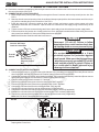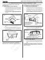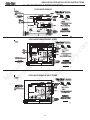
1
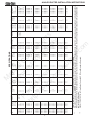
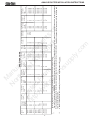
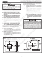
ANALOG DUCTED INSTALLATION INSTRUCTIONS
RECORD THIS UNIT INFORMATION FOR FUTURE REFERENCE:
Model Number
Serial Number
Date Purchased
M
N an
or ua
th l
Pr
w Co
e
i
st m
ht nte
tp d
R plim
V
:// F
en
w ro
S
w m
up ts
w
pl o
.n
y f
w
rv
su
pp
ly
.c
om
600 Series PENGUIN
579 Series BRISK AIR
590 Series QUICK COOL
591 Series HEAT PUMP
595 Series QUICK COOL
Roof Top Air Conditioner/Heat Pump
USED WITH
Part No. 3107541 and 3107546
Analog Relay Kit
WITH REMOTE ANALOG THERMOSTAT
USA
SERVICE OFFICE
The Dometic Corp.
509 So. Poplar St.
LaGrange, IN 46761
260-463-4858
CANADA
Dometic Dist.
866 Langs Dr.
Cambridge, Ontario
CANADA N3H 2N7
519-653-4390
For Service Center
Assistance Call:
800-544-4881
C
DUCTED
THIS UNIT IS DESIGNED FOR OEM INSTALLATION
ALL INITIAL INSTALLATIONS MUST BE APPROVED BY THE SALES DEPT.
! AVERTISSEMENT
! WARNING
This manual must be read and understood before installation, adjustment, service, or maintenance is performed. This unit must be installed
by a qualified service technician.
Modification of this product can be
extremely hazardous and could result in personal injury or property
damage.
MODELS
US
INSTALLATION
INSTRUCTIONS
REVISION
Form No. 3107163.101 6/03
(Replaces 3107163.093)
(French 3108062.071)
©2003 Dometic Corporation
LaGrange, IN 46761
Lire et comprendre ce manuel avant de
procéder à l'installation, à des réglages,
de l'entretien ou des réparations.
L'installation de cet appareil doit être
effectuée par un réparateur qualifié.
Toute modification de cet appareil peut
être extrêmement dangereuse et
entraîner des blessures ou dommages
matériels.
57908.321
57908.521
57912.321
57912.531
57912.621
57912.622
57912.631
57915.331
57915.336
57915.421
Important: These instructions
must stay with unit.
Owner read carefully.
1
57915.422
57915.426
57915.521
57915.522
57915.526
57915.531
57915.536
57915.621
57915.622
57915.626
57915.631
57915.731
59016.521
59016.621
59516.331
59516.336
59516.501
59516.531
59516.536
59516.601
59516.603
59516.606
59516.631
59528.601
59529.531
59529.601
59529.631
59530.531
59530.532
59530.536
59530.601
59530.631
59530.632
600312.321
600312.421
600315.321
600315.326
600315.421
ANALOG DUCTED INSTALLATION INSTRUCTIONS
1. GENERAL INFORMATION
SAFETY INSTRUCTIONS
A. Product features or specifications as described or illustrated are subject to change without notice.
B. This air conditioner is designed for:
1. Installation on a recreational vehicle during the time
the vehicle is manufactured.
2. Mounting on the roof of a recreational vehicle.
3. Connection to an air distribution system located in
the ceiling/roof cavity of the recreational vehicle.
4. Roof construction with rafters/joists on minimum of
16 inch centers.
5. Minimum of 2.00" and maximum of 5.50" distance
between roof to ceiling of recreational vehicle. Alternate installation methods will allow for roofs more
than 5.50" thick.
This manual has safety information and instructions to help users eliminate or reduce the risk of
accidents and injuries.
RECOGNIZE SAFETY INFORMATION
M
N an
or ua
th l
Pr
w Co
e
i
st m
ht nte
tp d
R plim
V
:// F
en
w ro
S
w m
up ts
w
pl o
.n
y f
w
rv
su
pp
ly
.c
om
!
C. The ability of the air conditioner to maintain the desired
inside temperature depends on the heat gain of the RV.
Some preventative measures taken by the occupants of
the RV can reduce the heat gain and improve the
performance of the air conditioner. During extremely high
outdoor temperatures, the heat gain of the vehicle may
be reduced by:
1. Parking the RV in a shaded area
2. Using window shades (blinds and/or curtains)
3. Keeping windows and doors shut or minimizing
usage
4. Avoiding the use of heat producing appliances.
This is the safety-alert symbol. When you see this
symbol in this manual, be alert to the potential for
personal injury.
Follow recommended precautions and safe operating instructions.
UNDERSTAND SIGNAL WORDS
A signal word , WARNING OR CAUTION is used
with the safety-alert symbol. They give the level of
risk for potential injury.
Operation on High Fan/Cooling mode will give optimum or
maximum efficiency in high humidity or high outside temperatures.
! WARNING indicates a potentially hazard-
Starting the air conditioner early in the morning and giving it
a "head start" on the expected high outdoor ambient will
greatly improve its ability to maintain the desired indoor
temperature.
ous situation which, if not avoided, could result in
death or serious injury.
For a more permanent solution to high heat gain, accessories like A&E outdoor patio and window awnings will reduce
heat gain by removing the direct sun. They also add a nice
area to enjoy company during the cool of the evening.
! CAUTION indicates a potentially hazard-
ous situation which, if not avoided may result in
minor or moderate injury.
D. Condensation
Note: The manufacturer of this air conditioner will not be
responsible for damage caused by condensed moisture on
ceilings or other surfaces. Air contains moisture and this
moisture tends to condense on cold surfaces. When air
enters the RV, condensed moisture may appear on the
ceiling, windows, metal parts, etc. The air conditioner removes this moisture from the air during normal operation.
Keeping doors and windows closed when this air conditioner
is in operation will minimize condensed moisture on cold
surfaces.
CAUTION
used without the safety alert
symbol indicates, a potentially hazardous situation which, if not avoided may result in property
damage.
Read and follow all safety information and instructions.
2
3
13,500
13,500
13,500
13,500
13,500
13,500
13,500
13,500
13,500
13,500
13,500
13,500
15,000
15,000
15,000
15,000
15,000
15,000
15,000
15,000
15,000
15,000
57915.422
57915.426
57915.521
57915.522
57915.526
57915.531
57915.536
57915.621
57915.622
57915.626
57915.631
57915.731
59016.521
59016.621
59516.331
59516.336
59516.501
59516.531
59516.536
59516.601
59516.603
59516.606
***
115VAC,
60 HZ., 1PH.
ELECTRICAL
RATING
12.3
12.9
11.5
11.5
12.9
12.7
11.5
12.9
12.9
11.5
11.0
11.3
11.0
11.0
11.0
12.1
12.1
11.5
11.5
12.1
12.1
12.1
8.5
8.5
11.4
12.1
11.5
6.9
6.6
9.5
8.0
8.5
AMPS
COMPRESSOR
RATED LOAD
77.0
71.0
50.0
50.0
77.0
60.0
50.0
71.0
77.0
50.0
54.4
56.0
54.4
54.4
54.4
59.0
59.0
50.0
50.0
59.0
59.0
59.0
48.3
48.3
58.0
59.0
50.0
36.0
34.0
53.0
53.0
48.3
ROTOR
AMPS
COMPRESSOR
LOCKED
2.0
2.0
2.5
2.5
2.5
2.0
2.5
2.5
2.5
2.5
2.5
2.5
2.5
2.5
2.5
2.5
2.5
2.5
2.5
2.5
2.5
2.5
2.5
2.5
2.5
2.5
2.5
2.5
2.5
2.5
2.5
2.5
AMPS
FAN MOTOR
RATED LOAD
5.6
6.0
5.8
5.8
6.0
5.6
5.8
6.0
6.0
5.8
5.8
5.8
5.8
5.8
5.8
5.8
5.8
5.8
5.8
5.8
5.8
5.8
5.8
5.8
5.8
5.8
5.8
5.8
5.8
5.8
5.8
5.8
ROTOR
AMPS
325 / 250
325 / 250
325 / 250
325 / 250
350 / 250
325 / 250
325 / 250
350 / 250
350 / 250
325 / 250
325 / 250
325 / 250
325 / 250
325 / 250
325 / 250
325 / 250
325 / 250
325 / 250
325 / 250
325 / 250
325 / 250
325 / 250
325 / 250
325 / 250
325 / 250
325 / 250
325 / 250
325 / 250
325 / 250
325 / 250
325 / 250
325 / 250
MAX/MIN
SCFM-HIGH
SPEED
SPECIFICATIONS
FAN MOTOR
LOCKED
0.40 / 1.10
0.40 / 1.10
0.40 / 1.10
0.40 / 1.10
0.40 / 1.10
0.40 / 1.10
0.40 / 1.10
0.40 /1.1 0
0.40 / 1.10
0.40 / 1.10
0.55 / 0.90
0.55 / 0.90
0.55 / 0.90
0.55 / 0.90
0.55 / 0.90
0.55 / 0.90
0.55 / 0.90
0.55 / 0.90
0.55 / 0.90
0.55 / 0.90
0.55 / 0.90
0.55 / 0.90
0.55 / 0.90
0.55 / 0.90
0.55 / 0.90
0.55 / 0.90
0.55 / 0.90
0.55 / 0.90
0.55 / 0.90
0.55 / 0.90
0.55 / 0.90
0.55 / 0.90
MAX/MIN
“ W. C.
TOTAL
STATIC
29.5
31.0
26.5
29
31.0
29.0
31.0
26.5
26.5
29.0
16.5
15.0
16.0
16.5
16.0
16.5
16.5
14.5
13.5
16.0
16.5
16.0
18.0
18.0
15.5
16.5
13.5
16.0
17.0
15.5
18.5
16.0
REFRIGERANT
R-22 (OZ)
12 AWG
Copper
up to 24’
MINIMUM
WIRE SIZE*
20 Amp
20 Amp
20 Amp
20 Amp
20 Amp
20 Amp
20 Amp
20 Amp
20 Amp
20 Amp
20 Amp
20 Amp
20 Amp
20 Amp
20 Amp
20 Amp
20 Amp
20 Amp
20 Amp
20 Amp
20 Amp
20 Amp
20 Amp
20 Amp
20 Amp
20 Amp
20 Amp
20 Amp
20 Amp
20 Amp
20 Amp
20 Amp
*** USER
SUPPLIED
AC CIRCUIT
PROTECTION
102
102
94
94
102
94
94
101
101
94
94
94
94
94
94
94
94
100
100
94
94
94
94
94
100
100
100
75
75
94
94
94
(POUNDS)
INSTALLED
WEIGHT
3.5 KW / 5.0 KW
3.5 KW / 5.0 KW
3.5 KW / 5.0 KW
3.5 KW / 5.0 KW
3.5 KW / 5.0 KW
3.5 KW / 5.0 KW
3.5 KW / 5.0 KW
3.5 KW / 5.0 KW
3.5 KW / 5.0 KW
3.5 KW / 5.0 KW
3.5 KW / 5.0 KW
3.5 KW / 5.0 KW
3.5 KW / 5.0 KW
3.5 KW / 5.0 KW
3.5 KW / 5.0 KW
3.5 KW / 5.0 KW
3.5 KW / 5.0 KW
3.5 KW / 5.0 KW
3.5 KW / 5.0 KW
3.5 KW / 5.0 KW
3.5 KW / 5.0 KW
3.5 KW / 5.0 KW
2.5 KW / 4.0 KW
2.5 KW / 4.0 KW
3.5 KW / 5.0 KW
3.5 KW / 5.0 KW
3.5 KW / 5.0 KW
2.5 KW / 4.0 KW
2.5 KW / 4.0 KW
2.5 KW / 4.0 KW
2.5 KW / 4.0 KW
2.5 KW / 4.0 KW
SIZE**
1 UNIT/ 2 UNITS
MINIMUM
GENERATOR
For wire lengths over 24 ft. consult the National Electric Code for proper sizing.
Dometic Corporation gives GENERAL guidelines for generator requirements. These guidelines come from experiences people have had in actual applications
When sizing the generator, the total power usage of your recreational vehicle must be considered. Keep in mind generators lose power at high altitudes and
from lack of maintenance.
CIRCUIT PROTECTION: Time Delay Fuse or HACR Circuit Breakers Required.
11,000
11,000
13,500
13,500
13,500
57912.622
57912.631
57915.331
57915.336
57915.421
*
**
7,180
7,100
11,000
11,000
11,000
(BTU/HR)
COOLING
NOMINAL
CAPACITY
57908.321
57908.521
57912.321
57912.531
57912.621
MODEL
NO.
M
N an
or ua
th l
Pr
w Co
e
i
st m
ht nte
tp d
R plim
V
:// F
en
w ro
S
w m
up ts
w
pl o
.n
y f
w
rv
su
pp
ly
.c
om
ANALOG DUCTED INSTALLATION INSTRUCTIONS
4
13,500
13,500
13,500
600315.321
600315.326
600315.421
***
115VAC,
60 HZ., 1PH.
ELECTRICAL
RATING
60.0
60.0
50.0
53.0
50.0
9.5
10.7
12.4
12.4
11.5
48.3
48.3
48.3
45.6
49.0
53.0
53.0
53.0
COMPRESSOR
LOCKED
ROTOR
AMPS
8.0
8.0
8.5
6.0
6.9
7.8
8.0
7.8
AMPS
COMPRESSOR
RATED LOAD
3.1
3.1
3.1
2.0
2.0
2.5
3.1
3.1
2.0
2.0
2.0
2.5
2.0
FAN MOTOR
RATED LOAD
AMPS
8.8
8.8
8.8
5.6
5.6
5.8
8.8
8.8
5.6
5.6
5.6
5.8
5.6
335 / 250
335 / 250
335 / 250
335/ 250
335 / 250
325 / 250
335 / 250
335 / 250
325 / 250
325 / 250
325 / 250
325 / 250
325 / 250
SCFM-HIGH
SPEED
MAX/MIN
SPECIFICATIONS
FAN MOTOR
LOCKED
ROTOR
AMPS
0.12 / 0.65
0.12 / 0.65
0.12 / 0.65
0.40 / 1.10
0.40 / 1.10
0.12 / 0.65
0.12 / 0.65
0.40 / 1.10
0.41 / 1.10
0.40 / 1.10
0.40 / 1.10
0.40 / 1.10
0.40 / 1.10
TOTAL
STATIC
MAX/MIN
“ W. C.
15.5
17.0
15.5
19.0
19.0
18.0
16.5
16.0
16.5
18.5
19.0
18.5
19.0
REFRIGERANT
R-22 (OZ)
12 AWG
Copper
up to 24’
MINIMUM
WIRE SIZE*
20 Amp
20 Amp
20 Amp
15 Amp
15 Amp
15 Amp
20 Amp
20 Amp
15 Amp
15 Amp
15 Amp
15 Amp
15 Amp
SUPPLIED
AC CIRCUIT
PROTECTION
*** USER
96
102
96
93
94
94
95
101
92
94
94
94
94
INSTALLED
WEIGHT
(POUNDS)
MINIMUM
3.5 KW / 5.0 KW
3.5 KW / 5.0 KW
3.5 KW / 5.0 KW
3.5 KW / 5.0 KW
3.5 KW / 5.0 KW
2.5 KW / 4.0 KW
2.5 KW / 4.0 KW
2.5 KW / 4.0 KW
3.5 KW / 5.0 KW
3.5 KW / 5.0 KW
3.5 KW / 5.0 KW
3.5 KW / 5.0 KW
3.5 KW / 5.0 KW
GENERATOR
SIZE**
1 UNIT/ 2 UNITS
For wire lenghts over 24 ft. consult the National Electric Code for proper sizing.
Dometic Corporation gives GENERAL guidelines for generator requirements. These guidelines come from experiences people have had in actual applications
When sizing the generator, the total power usage of your recreational vehicle must be considered. Keep in mind generators lose power at high altitudes and
from lack of maintenance.
CIRCUIT PROTECTION: Time Delay Fuse or HACR Circuit Breakers Required.
N/A
N/A
N/A
11,000
11,000
59530.601
59530.631
59530.632
600312.321
600312.421
*
**
N/A
N/A
N/A
N/A
N/A
(BTU/HR)
COOLING
CAPACITY
NOMINAL
59528.601
59529.531
59530.531
59530.532
59530.536
MODEL
NO.
M
N an
or ua
th l
Pr
w Co
e
i
st m
ht nte
tp d
R plim
V
:// F
en
w ro
S
w m
up ts
w
pl o
.n
y f
w
rv
su
pp
ly
.c
om
ANALOG DUCTED INSTALLATION INSTRUCTIONS
ANALOG DUCTED INSTALLATION INSTRUCTIONS
2. PRECAUTIONS
It is preferred that the air conditioner/heat pump be installed
on a relatively flat and level roof section measured with the
RV parked on a level surface; however,
1.
Up to an 8° slant to either side or front-to-back is
acceptable on 600 Series Air Conditioners/heat
pump.
2.
Up to a 15° slant to either side or front-to-back is
acceptable on 579, 590, 591 or 595 Series Air
conditioners/heat pump.
AFTER LOCATION HAS BEEN SELECTED:
a. Check for obstructions in the area where air
conditioner/heat pump will be installed. See
FIG. 1.
b. The roof must be designed to support 130
pounds when the RV is in motion. Normally 200
pound static load design will meet this requirement.
! WARNING
Improper installation may damage equipment, could endanger life, cause serious
injury and/or property damage.
M
N an
or ua
th l
Pr
w Co
e
i
st m
ht nte
tp d
R plim
V
:// F
en
w ro
S
w m
up ts
w
pl o
.n
y f
w
rv
su
pp
ly
.c
om
A. Read Installation and Operating instructions carefully
before attempting to start your air conditioner/heat
pump installation.
B. Dometic Corporation will not be liable for any damages or injury incurred due to failure in following these
instructions.
C. Installation must comply with the National Electrical
Code and any State or Local Codes or regulations.
D. DO NOT add any devices or accessories to this air
conditioner/heat pump except those specifically
authorized by Dometic.
E. This equipment must be serviced by qualified personnel and some states require these people to be
licensed.
CAUTION
It is the responsibility of the installer of this
air conditioner/heat pump system to ensure
structural integrity of the RV roof. Never create a low spot on the roof where water will
collect. Water standing around the air conditioner/heat pump may leak into the interior
causing damage to the product and the RV.
3. CHOOSING LOCATION FOR THE
AIR CONDITIONER/HEAT PUMP
This air conditioner/heat pump is specifically designed for
installation on the roof of a recreational vehicle (RV).
A. For One Unit Installation:
The air conditioner/heat pump should be mounted slightly
forward of center (front to back) and centered from side
to side.
B. For Two Unit Installations:
Install one air conditioner/heat pump one-third and one
air conditioner/heat pump two-thirds from front of RV and
centered from side to side.
FIG. 1 AIR CONDITIONER/HEAT PUMP DIMENSIONS (On Top of
Vehicle)
600 SERIES
579, 590, 591 & 595 SERIES
KEEP THIS AREA FREE OF OBSTRUCTIONS
7-5/8”
5-1/4”
14-7/8”
REAR
OF
UNIT
14-1/4" x 14-1/4”
(±1/8) OPENING
7-5/8”
18"
5
ANALOG DUCTED INSTALLATION INSTRUCTIONS
4. AIR DISTRIBUTION SYSTEM
SIZING & DESIGN
M
N an
or ua
th l
Pr
w Co
e
i
st m
ht nte
tp d
R plim
V
:// F
en
w ro
S
w m
up ts
w
pl o
.n
y f
w
rv
su
pp
ly
.c
om
The Installer of this air conditioner/heat pump system must design the air distribution system for their particular application. Several
requirements for this system MUST be met for the air conditioner/heat pump to operate properly. These requirements are as
follows:
A. The duct material must meet or exceed any agency or RVIA Standard that may be in existence at the time the RV is produced.
B. All discharge air ducts must be properly insulated to prevent condensation from forming on their surfaces or adjacent surfaces
during operation of the air conditioner/heat pump. This insulation must be R-7 minimum.
C. Ducts and their joints must be sealed to prevent condensation from forming on adjacent surfaces during operation of the air
conditioner/heat pump.
D. Return air openings must have 40 square inches minimum free area including the filter.
E. Return air to the air conditioner/heat pump must be filtered to prevent dirt accumulation on air conditioner/heat pump cooling
surface.
CAUTION
It is the responsibility of the installer to insure the ductwork will not collapse or bend
during and after the installation. Dometic
Corporation will not be liable for roof structural or ceiling damage due to improperly insulated, sealed or collapsed ductwork.
AIR DISTRIBUTION
DUCT SIZING & DESIGN CHART
Return Air Cover Model
3105007.XXX
3105935.XXX
3308120.XXX
Genesis Air Filtration System
2.0 In. Min. - 5-1/2 In. Max.
2.0 In. Min. - 5-1/2 In. Max.
21.0 Sq. In. Min.
32.0 Sq. In. Min.
1-1/2 In. Min. - 2-1/2 In. Max.
7.0 In. Min. - 10.0 In. Max.
15.0 Ft. Min. - 40.0 Ft. Max.
1/3 Total Duct Length
2.0 In. Min. - 2-1/2 In. Max.
8.0 In. Min. - 10.0 In. Max.
15.0 Ft. Min. - 40.0 Ft. Max.
1/3 Total Duct Length
4 Min.
14.0 Sq. In.
5.0 In. Min. - 8.0 In. Max.
15.0 In.
4 Min.
14.0 Sq. In.
5.0 In. Min. - 8.0 In. Max.
15.0 In.
Roof Cavity Depth
Duct Cross Sectional Area
Duct Size
Depth
Width
Total Duct Length
Duct Length (short run)
Register Requirements
Number Required Per Run
Register Free Air Area
Distance From Duct End
Distance From Elbow
Total System Static Air Pressure
Blower at High Speed,
Filter & Grill In Place
0.55 - 0.90 In. W.C. 579 Series
0.55 - 0.90 In. W.C. 579 Series
0.40 - 1.10 In. W.C. 590, 591, 595 Series 0.40 - 1.10 In. W.C. 590, 591, 595 Series
0.12 - 0.65 In. W.C. 600 Series
0.12 - 0.65 In. W.C. 600 Series
Note: Duct sizes listed are inside dimensions.
6
ANALOG DUCTED INSTALLATION INSTRUCTIONS
5. AIR DISTRIBUTION SYSTEM INSTALLATION
M
N an
or ua
th l
Pr
w Co
e
i
st m
ht nte
tp d
R plim
V
:// F
en
w ro
S
w m
up ts
w
pl o
.n
y f
w
rv
su
pp
ly
.c
om
A. The Dometic Corporation recommends the basic configuration shown on page 8, for installing this air conditioner/heat pump
system. We have found by testing , that this configuration works best in most applications of this air conditioner/heat pump
system. It is the responsibility of the Installer of this system to review each RV floor plan and determine the following:
1. Duct size
2. Duct layout
3 Register size
4. Register location
5. Thermostat location
These items must be determined in conjunction with the Air Distribution System and Sizing and Design Requirements listed
in the chart on page 6.
Important: Alternate configurations and methods may be used which still allow the air conditioner/heat pump
to operate properly; however, these alternate configurations and methods must be approved by the Dometic
Corporation in writing. The following instructions are based upon the use of Dometic Return Air Kits 3105007.XXX,
3105935.XXX, or Genesis Air Filtration System 3308120.XXX. The 3107541.XXX and 3107546.XXX has the mounting
bolts supplied for use with these kits.
B. ROOF AND CEILING OPENING PREPARATION
1. A 14-1/4" x 14-1/4" (±1/8") opening must be cut through the roof and ceiling of the RV. This opening must be located
between the roof reinforcing members.
! WARNING
There may be electrical wiring between the
roof and the ceiling. Disconnect 115 volt AC
power cord and the positive (+) 12 volt DC
terminal at the supply battery. Failure to follow this instruction may create a shock hazard causing death or severe personal injury.
2. Mark a 14-1/4" x 14-1/4" (±1/8") square on the roof and carefully cut the opening.
3. Using the roof opening as a guide, cut the matching hole in the ceiling.
4. The opening created must be framed to provide adequate support and prevent air from being drawn from the roof cavity.
Lumber 3/4" or more in thickness must be used. Remember to provide an entrance hole for power supply wiring and
thermostat cable.
5. The 14-1/4" x 14-1/4" (±1/8") opening is part of the return air system of the air conditioner/heat pump and must be finished
in accordance with NFPA Standard 501C Section 2.7.
6. Route a copper 12 AWG (max. length 24'), with ground, supply line from the fuse or circuit breaker box to the roof opening.
a. This supply line must be located in the front portion of the 14-1/4" x 14-1/4" (±1/8") opening.
b. The power supply MUST be on a separate Time Delay Fuse or HACR Circuit Breaker ( 20 amp for 579, 590, 591,59516
and 600 series and 15 amp for 59529 and 59530.
c. Make sure at least 15" of supply wire extends into the roof opening. This ensures easy connection at the junction
box.
d. Wiring must comply with all National, State and Local Wiring Codes.
e. Use a steel sleeve and a grommet or equivalent methods to protect the wire where it passes into the opening.
7. Route a DEDICATED 12V DC supply line (18–22 AWG) from the RV's converter or battery to the roof opening. See Section
6. Thermostat & Cable Installation, B. Cable Installation.
a.
This supply line must be located in the front portion of the 14-1/4" x 14-1/4" (±1/8") opening.
b.
Make sure that at least 15" of supply wire extends into the roof opening.
7
ANALOG DUCTED INSTALLATION INSTRUCTIONS
C. AIR DISTRIBUTION DUCT INSTALLATION
1. Install the Air Distribution Ducts in the RV Roof Cavity. The Distribution System must meet:
a. RV’s requirements
b. System requirements listed in Section 4 on page 6 of this Manual. Terminate the start of the Duct at the back edge
of the 14-1/4" x 14-1/4" (±1/8") opening previously cut. See FIG. 2, 3, & 4.
TOP VIEW
(BACK OF RV)
FIG. 2
FRAME
DUCT
14-1/4" (±1/8”)
OPENING
FRAME
DUCT
M
N an
or ua
th l
Pr
w Co
e
i
st m
ht nte
tp d
R plim
V
:// F
en
w ro
S
w m
up ts
w
pl o
.n
y f
w
rv
su
pp
ly
.c
om
AC POWER
SUPPLY WIRE
FRAME
LOW VOLTAGE WIRES:
12VDC
Furnace
Load Shed
Sensors
ROOF
CCC, CONTROL CABLE(S)
or 7-Wire Analog Cable
SIDE VIEW
(TOWARD BACK OF RV)
14-1/4" (±1/8”)
OPENING
INSULATION
DUCT
FIG. 3
DUCT
CEILING
INSULATION
Duct Size And Requirements For 3105007.XXX And 3105935.XXX Return Air Cover
Register Required
Register Required
Short Duct Run Minimum
1/3 Total Duct Length
Total Outlet Air Area
Minimum 21.0 Sq. In.
Ducts
Depth
Width
Total Length
Min.
1-1/2”
7.0”
15.0’
Registers
8 Min.-- 12 Max.
(Per Unit)
14 Sq. In Free Area
Per Register
Max.
2-1/2”
10.0”
40.0’
Register Required
Note: Duct Size is Inside Dimensions
Register Required
Roof
Rafters
14-1/4"x14-1/4" (±1/8")
Roof Opening
FIG. 4
Duct Size And Requirements For 33308120.XXX Genesis Air Filtration System
Register Required
Register Required
Short Duct Run Minimum
1/3 Total Duct Length
Total Outlet Air Area
Minimum 32.0 Sq. In.
Ducts
Depth
Width
Total Length
Min.
2.0”
8.0”
15.0’
Registers
8 Min.-- 12 Max.
(Per Unit)
14 Sq. In Free Area
Per Register
Max.
2-1/2”
10.0”
40.0’
Register Required
Note: Duct Size is Inside Dimensions
Roof
Rafters
Register Required
14-1/4"x14-1/4" (±1/8")
Roof Opening
8
ANALOG DUCTED INSTALLATION INSTRUCTIONS
6. THERMOSTAT & CABLE INSTALLATION
M
N an
or ua
th l
Pr
w Co
e
i
st m
ht nte
tp d
R plim
V
:// F
en
w ro
S
w m
up ts
w
pl o
.n
y f
w
rv
su
pp
ly
.c
om
A. LOCATION
The proper location of the thermostat is very important to ensure that it will provide a comfortable RV temperature. Observe
the following general rules when selecting a location.
1. Locate the thermostat 54" above the floor.
2. Install thermostat on a partition, NEVER on an outside wall.
3. NEVER expose it to direct heat from lamps, sun or other heat producing items.
4. Avoid locations close to doors that lead outside, windows or adjoining outside walls or directly under cabinets or overhangs
which limit air movement.
5. Avoid locations close to supply registers and the air from them.
6. NEVER locate thermostat in a room that is warmer or cooler than the rest of the coach - such as the kitchen.
7. The major living area is normally a good location.
B. CABLE INSTALLATION
1. A seven-conductor cable, 18 to 22 AWG is to be used for low voltage connections.
2. Choose the shortest, direct route from the 14-1/4" x 14-1/4" (±1/8") opening to the thermostat location selected.
3. Consider where screws, nails or staples might contact the cable.
4. Leave approximately 6" of cable extending through the wall for connection to the thermostat.
5. Leave approximately 15" of cable extending into the 14-1/4" x 14-1/4" (±1/8") opening for connection at unit.
6. If system is to control a gas furnace: Route two 18 gauge wires from the furnace to 14-1/4" x 14-1/4" (±1/8") opening at
this time. See Section 4. Air Distribution System Installation; A Roof and Ceiling Opening Preparation.
7. PLACING THE AIR CONDITIONER/HEAT PUMP ON THE ROOF
A. Remove the air conditioner/heat pump from the carton and discard carton. The unit mounting bolts are in separate plastic bag
with the control kit. Be sure to place this in the RV.
B. Place the air conditioner/heat pump on the roof.
FIG. 5
! CAUTION
Please Recycle
All Cardboard
This unit weighs approximately 100 pounds.
To prevent back injury, use a mechanical
hoist to place air Conditioner/heat pump on
roof.
C. Lift and place the unit over the prepared opening usingthe gasket on unit as a guide. The gasket end goes toward the front
of the RV. Sliding the unit on the roof will damage the roof gasket. See FIG. 6.
FIG. 6
CAUTION
Do not slide the unit. This may damage the
neoprene gasket attached to the bottom and
create a leaky installation.
Front
D.
Place 3107541 or 3107546 Relay Kit and 3105007.XXX, 3105935.XXX or 3308120.XXX Return Air Cover Kit, inside the RV.
These cartons contain mounting hardware for the air conditioner/heat pump and will be used inside the RV. This completes
the outside work. Minor adjustments can be done from the inside of the RV if required.
9
ANALOG DUCTED INSTALLATION INSTRUCTIONS
8. INSTALLATION OF COLD CONTROL
A. Remove parts package, control box and thermostat from the 3107541.XXX or 3107546.XXX Control Kit carton.
B. Freeze Control Installation 579, 590, 591, & 595 Series Brisk Air Models (See FIG. 7.)
1. Snap freeze control into place on return bend located at left side of evaporator coil as follows:
a. Locate “D” shaped notch in flange of evaporator coil.
b. Place the horseshoe end of the freeze control through this notch and snap onto the coil return bend. When positioned
correctly, control wires will be 900 to direction of coil fin surface.
c. Remove installation notice hang tag from freeze control.
Brisk Air Model Series
579, 590, 591, & 595
M
N an
or ua
th l
Pr
w Co
e
i
st m
ht nte
tp d
R plim
V
:// F
en
w ro
S
w m
up ts
w
pl o
.n
y f
w
rv
su
pp
ly
.c
om
FIG. 7
Coil
Return
Bend
Remove
Hang Tag
Freeze Control
With Wires To Left Side
C. Freeze Control installation on 600 Series Penguin Models (See FIG. 8.)
1. Snap freeze control into place on return bend located at right side of evaporator coil as follows:
a. Locate “D” shaped notch in flange of evaporator coil.
b. Place the horseshoe end of the freeze control through this notch and snap onto the coil return bend. When positioned
correctly, control wires will be 900 to direction of coil fin surface.
c. Remove installation notice hang tag from freeze control.
FIG. 8
Penguin Model Series 600
Coil
Return
Bend
Remove
Hang Tag
Freeze Control
With Wires To Right Side
10
ANALOG DUCTED INSTALLATION INSTRUCTIONS
9. WIRING OF CONTROL SYSTEM
M
N an
or ua
th l
Pr
w Co
e
i
st m
ht nte
tp d
R plim
V
:// F
en
w ro
S
w m
up ts
w
pl o
.n
y f
w
rv
su
pp
ly
.c
om
A. Position the control box (standing up) with the 6 pin connector to the curb side of the vehicle and the service access facing
the rear of the vehicle. See FIG. 9.
B. CONNECTION OF 115 VOLT AC SUPPLY
1. Route the previously run AC power supply line through the Romex Connector and into relay control junction box. See
FIG. 9.
2. Reach up into the return air opening of the air conditioner/heat pump and pull the wire harness down and fit the six pin
plug into the matching plug on the control box. See FIG. 9.
3. Inside the control box, connect the white to white; black to black; and green to green or bare copper wire using
appropriate sized twist wire connectors. Tape the twist wire connectors to the supply wiring to assure they do not
vibrate off.
4. Tighten screws on Romex connector being careful not to pinch and cut into the insulation on power supply leads.
5. Push excess wires into junction box. Install junction box cover, with model number/serial number facing out onto the
relay control box with #8 x 3/8” blunt point Phillips head screw provided.
Note: Model Number /Serial Number label must face out.
! WARNING
FIG. 9
Center Unit From Below
Connect AC Power
Leads in Control Box
Disconnect 115 volt AC. Failure to follow
these instructions could create a shock hazard causing death or severe personal injury.
Gasket
! WARNING
This product is equipped with a 3-wire
(grounded) system for protection against
shock hazard. Make sure that the appliance
is wired into a properly grounded 115 volt AC
circuit and the polarity is correct. Failure to
do so could result in death, personal injury
or damage to the equipment.
Front Of
Vehicle
Connect 6 Pin
Plug Into Control
Box.
B. CONNECTION OF LOW VOLTAGE WIRES
1. Connect the previously run +12VDC to the red wire labeled +12V protruding from the relay control box (Do not connect
wires if using the 3308120.XXX Genesis Air Filtration System Return Air Kit Return Air Kit).
2. Connect the previously run -12VDC to the black wire labeled - 12V protruding from the relay control box (Do not connect
wires if using the 3308120.XXX Genesis Air Filtration System Return Air Kit).
3. Connect red/white wire to the thermostat +7.5 terminal.
4. Connect the unit/control box green wire to the thermostat “GND” terminal.
5. Connect the unit/control box yellow wire to the thermostat “COOL” Terminal.
6. Connect the unit/control box tan wire to the thermostat “FAN” terminal.
7. Connect the unit/control box blue wire to the thermostat “HI FAN” terminal.
8. Connect the unit/control box orange wire to the thermostat “HS/HP” terminal (if applicable).
9. Connect the unit/control box unit white wire to the thermostat “FUR” terminal (if applicable).
10. Connect the unit/control box blue/white wires to the two furnace control wires (if applicable).
Note: See FIG. 9A for Thermostat connection points.
FIG. 9A
D. Plug unit electrical cord into the mating connector on the relay control box. These connectors are polarized and will easily
snap together. Do not force.
11
ANALOG DUCTED INSTALLATION INSTRUCTIONS
10. INSTALLATION OF AIR CONDITIONER/HEAT PUMP
Installing unit with 3105007.XXX or 3105935.XXX
Return Air Cover
A. INSTALLATION OF CEILING TEMPLATE
1. Check gasket alignment of the air conditioner/heat
pump over the roof opening and adjust if necessary.
Unit may be moved from below by slightly lifting
and sliding. See FIG. 11A.
2. Remove return air cover and ceiling template from
the 3105007.XXX or 3105935.XXX kit carton. See
FIG. 10A
Do Not Peel Tape Off
Adhesive
FIG. 10B
M
N an
or ua
th l
Pr
w Co
e
i
st m
ht nte
tp d
R plim
V
:// F
en
w ro
S
w m
up ts
w
pl o
.n
y f
w
rv
su
pp
ly
.c
om
FIG.
10A
Installing unit with 3308120.XXX Genesis Air Filtration System Return Air Kit Return Air Cover
A. INSTALLATION OF FOAM DIVIDER
1. Locate the foam divider and insert it corner to corner in the 14-1/4" x 14-1/4" (±1/8") opening with
the adhesive tape up (Do not remove paper to expose adhesive). The foam divider should be level
with the ceiling (±1/4"). Tear off the excess at the
pre-cut perforations in divider. See FIG. 10B.
Divider Plate
Base Pan
Ceiling
Template
Upside
Down
Foam
Divider
Return Air
Cover
Return Air
Grill
3.
4.
Ceiling
Place Foam Divider in
(14-1/4" x 14-1/4" (±1/8")
Ceiling Opening against
Base Pan Bottom
Locate 1/4 “ unit mounting bolts in the parts package.
Hold the ceiling template up to the 14-1/4" x 14-1/
4" (±1/8") opening. Be sure the large plate faces
the rear of the RV.
Foam Divider Ceiling
Level (±1/4") Tear Off
Excess
2. Peel the paper off of the foam divider and stick it in
place on the center of the rear edge of the return air
opening on the ceiling template See. FIG. 11B.
FIG. 11B
FIG. 11A
Center Unit From Below
Foam Divider
Adhesive
Peel Off Paper - Center Divider - Stick To
Rear Flange On Ceiling Template
B. INSTALL CEILING TEMPLATE
1. Place the ceiling template up into the return air opening in the ceiling and plug the unit's control cable
into the control box before installing the mounting
bolts.
Installing unit with 3308120.XXX Genesis Air Filtration
System Return Air Kit Return Air Cover - continued on
page 13, column B.
Roof
Gasket
Installing unit with 3105007.XXX or 3105935.XXX
Return Air Cover - continued on page 13, column A.
12
ANALOG DUCTED INSTALLATION INSTRUCTIONS
Installing unit with 3308120.XXX Genesis Air Filtration
System Return Air Kit Return Air Cover - continued from
page 12, column B.
2. Install relay box on ceiling template with blunt selftapping screws depending on the model see FIG.
12B for Brisk Air units and Fig.13B for Penguin units.
Installing unit with 3105007.XXX or 3105935.XXX Return Air Cover - Continued from page 10, column A.
5. Start each mounting bolt through the ceiling template and up into the unit base pan by hand. Install
wood screw in each end of the ceiling template.
This insures a tight fit of the return air cover to ceiling. Evenly tighten mounting bolts to compress
gasket to 1/2" this will be a torque of 40 - 50
inch pounds. See FIG. 12A.
Control Box
FIG. 12B
CAUTION
If bolts are left loose there may not be adequate roof seal or if over tightened, damage
may occur to the air conditioner/heat pump
base or ceiling template. Tighten to specifications listed in this manual.
M
N an
or ua
th l
Pr
w Co
e
i
st m
ht nte
tp d
R plim
V
:// F
en
w ro
S
w m
up ts
w
pl o
.n
y f
w
rv
su
pp
ly
.c
om
Brisk Air Models Mount
Control Box on Edge To
The Flange on Ceiling
Template
FIG. 12A
Vehicle
Front
To Front of RV
Screw
Finger
Tight
FIG. 13B
Tighten to
compress
gasket to 1/2"
Three
Screws
Control Box
Penguin Models Lay
Control Box Flat On Top
Of Ceiling Template
B. INSTALLATION OF DIVIDER PLATE
1. Measure the ceiling to roof thickness:
a. If distance is 2.0” - 3-3/4”, remove perforated tab
from divider plate.
b. If distance is 3-3/4” - 5-1/2”, remove no tabs.
2. Remove the backing paper from double sided tape
located on ceiling template. See FIG. 13A.
Two
Screws
Vehicle
Front
3. Start each mounting bolt through the ceiling template and up into the unit base pan by hand. Evenly
tighten mounting bolts to compress gasket to
1/2" this will be a torque of 40 - 50 inch pounds.
CAUTION
FIG. 13A
If bolts are left loose there may not be adequate roof seal or if over tightened, damage
may occur to the air conditioner/heat pump
base or ceiling template. Tighten to specifications listed in this manual.
Peel Backing Paper Off
Foam Insulation On Divider
Plate
Installing unit with 3308120.XXX Genesis Air Filtration
System Return Air Kit Return Air Cover - continued on
page 14, column B.
Installing unit with 3105007.XXX or 3105935.XXX
Return Air Cover - continued on page 14, column A.
13
ANALOG DUCTED INSTALLATION INSTRUCTIONS
Installing unit with 3308120.XXX Genesis Air Filtration
System Return Air Kit Return Air Cover - continued from
page 13, column B.
4. Use Aluminum foil tape (not supplied) to seal the
ends of the foam divider to the sides of the opening.
Make sure the area behind the flange on the ceiling
template is sealed. See FIG. 14B.
Installing unit with 3105007.XXX or 3105935.XXX Return Air Cover - Continued from page 13, column A.
3. Place divider plate up to bottom of air conditioner/
heat pump base pan firmly. The foam tape on the
divider plate must seal to bottom of base pan. See
FIG. 14A.
Note: The adhesive on the insulation is extremely
CAUTION
FIG. 14B Use Aluminum Foil Tape To Seal the
Foam Divider To The Sides of 14-1/4"
x 14-1/4" (±1/8") Ceiling Opening
Improper installation and sealing of divider
plate will cause the compressor to quick
cycle on the cold control. This may result in
fuse or circuit breaker opening and/or lack of
cooling.
M
N an
or ua
th l
Pr
w Co
e
i
st m
ht nte
tp d
R plim
V
:// F
en
w ro
S
w m
up ts
w
pl o
.n
y f
w
rv
su
pp
ly
.c
om
Route wires
through Slot
Catch Flange In Groove Of
Return Air Cover
FIG. 14A
sticky. Be sure the part is located where desired
before pressing into place.
4. With slight pressure then push the divider plate
against the double sided tape on the ceiling template.
5. Locate the 1/8” x 7” x 18” self -adhesive insulation
supplied with the return air kit. Remove the backing
paper from the insulation and carefully stick onto
the ceiling template divider panel. See FIG. 15A.
a. Excess width is intended to seal the divider plate
to the sides of the 14-1/4" x 14-1/4" (±1/8")
opening. This is to help prevent cold air discharge
from circulating into the air conditioner/heat
pump return air opening.
b. If the insulation is too high, stick excess height
of insulation to the air conditioner/heat pump
base pan. Do not cover up unit rating plate.
FIG. 15A
14
Make Sure To Seal
Behind Flange
ANALOG DUCTED INSTALLATION INSTRUCTIONS
11. INSTALLATION OF INSIDE DECORATIVE COVER.
Installing unit with 3308120.XXX Genesis Air Filtration System Return Air Kit Return Air Cover
A. Install the slider in the return air cover and raise it to
Installing unit with 3105007.XXX or 3105935.XXX
Return Air Cover
A. Locate the relay control box on the ceiling template
with the white 6 connector plug on the right (curb side)
side of RV.
B. Drive two #10 x 3/8” blunt point Phillips head screws
through the ceiling template into holes in control box to
hold it in place.
C. Remove the return air grill from the return air cover.
D. Place the return air cover up to the ceiling template.
E. Install cover to template with #8 x 3/8” pointed Phillips
head screws provided (6 required).
F. Reinstall filter return air grill into return air cover. Align
tabs with mating notches and snap into place
G. Install two hole plugs into screw holes in back of return
air cover. See FIG. 16A.
M
N an
or ua
th l
Pr
w Co
e
i
st m
ht nte
tp d
R plim
V
:// F
en
w ro
S
w m
up ts
w
pl o
.n
y f
w
rv
su
pp
ly
.c
om
the ceiling template. Route the wires from the return air
cover through the template slot leaving about 3” between, and position wire where they can be reached
after plastic cover is installed. See FIG. 15B. Place the
front of the return air cover against the ceiling and slide
towards the rear. The flange on the ceiling template will
catch in the groove on the return cover. Adjust the position (right to left) and install the front two screws. Install the remaining screws.
Note: Number 10 cabinet screw can be used to replace the two front screws to hold the plastic cover
flush to the ceiling.
1. Connect together the DC wires (3) black negative
and (3) red positive from the supply, control box and
filter indicator.
B. Insert the filter from the right side (looking toward the
RV front) over the wires. Make sure the wires are se-
FIG. 16A
Return Air
Cover
Hole
Plugs
cured above the filter and will stay out of its way.
C. Place grill on return air cover and snap in place. Decal
is on end over circuit board.
D. Place slide handle through slots in grill into the slide
posts. Handle will fit in either direction.
Return
Air Grill
FIG. 15B
This completes the installation of the air conditioner/
heat pump. We recommend that power be supplied to
the air conditioner/heat pump and check for proper operation. Refer to Operating Manual or Users Guide for a
description of the air conditioner/heat pump operation.
Foam
Divider
Ceiling
Template
Slider
Filter
Return Air
Cover
Grill
Handle
Micro-Therm Filter System
FILTER
RESET
CLEAN
FILTER
This completes the installation of the air conditioner/
heat pump. We recommend that power be supplied to
the air conditioner/heat pump and check for proper operation. Refer to Operating Manual or Users Guide for a
description of the air conditioner/heat pump operation.
15
ANALOG DUCTED INSTALLATION INSTRUCTIONS
12. RELAY KIT FIELD WIRING DIAGRAM
COOLING/FURNACE
3107750.014
R
115 VAC 60 Hz 1 O
USE COPPER CONDUCTORS
ONLY
509 S. POPLAR ST.
LAGRANGE, IN 46761
FURNACE
115VAC, 60Hz, 1PH
BLUE/WHITE
3 AMP FUSE
FIELD WIRING
FACTORY WIRING
LINE SPLICE
SOLAR/FILTER
INDICATOR
IF USED
BLUE/WHITE
BLACK
RED
T3 T4
FREEZE
CONTROL (N.O.)
E155095
- 12 VDC
+ POWER
SUPPLY
PART No. 3107541.009
SERIAL No.
TAN
BLUE
579, 590, 595, 600
YELLOW
RELAY BOARD
T-STAT
WHITE
RED/WHT
GREEN
N.O.
BLUE
BLACK
N/C
RED
WHITE
GRY/YEL
HI FAN
WITHOUT HEATSTRIP OPTION
PASSED
DIELECTRIC
M
N an
or ua
th l
Pr
w Co
e
i
st m
ht nte
tp d
R plim
V
:// F
en
w ro
S
w m
up ts
w
pl o
.n
y f
w
rv
su
pp
ly
.c
om
K4
FOR USE WITH AIR CONDITIONER:
COM
LO FAN
BLACK
WHITE
GRN/YEL
1
2
3
4
5
6
ELECTRIC
CONNECTION
FROM A/C
COOLING/FURNACE/HEAT STRIP
3107759.015
R
GRAY
1
N/C 2
WHITE 3
3 AMP FUSE
HS
BLUE/WHITE
FURNACE
BLUE/WHITE
SOLAR/FILTER
INDICATOR
IF USED
- 12 VDC
+ POWER
SUPPLY
T4
T3
FREEZE
CONTROL (N.O.)
509 S. POPLAR ST.
LAGRANGE, IN 46761
115VAC, 60Hz, 1PH
BLACK
RED
ORANGE
E155095
PART No. 3107541.017
SERIAL No.
TAN
BLUE
RELAY BOARD
FOR USE WITH AIR CONDITIONER:
T-STAT
YELLOW WHITE
RED/WHT
579, 590, 595, 600
FOR A/C WITH OPTIONAL HEATSTRIP
GREEN
115 VAC 60 Hz 1 O
USE COPPER CONDUCTORS ONLY
N.O.
K5
FIELD WIRING
FACTORY WIRING
LINE SPLICE
COM
N.O.
K4
HI FAN
COM
LO FAN
BLACK
WHITE
GRN/YEL
BLUE
BLACK
N/C
RED
WHITE
GRY/YEL
1
2
3
4
5
6
ELECTRICAL
CONNECTION
FROM A/C
PASSED
DIELECTRIC
COOLING/FURNACE/ HEAT PUMP
3107543.021
R
3 AMP FUSE
BLUE/WHITE
SOLAR/FILTER
INDICATOR
IF USED
BLUE/WHITE
FIELD WIRING
FACTORY WIRING
LINE SPLICE
T3
509 S. POPLAR ST.
LAGRANGE, IN 46761
115VAC, 60Hz, 1PH
FURNACE
BLACK
RED
VIOLET
ORANGE
BLUE
YELLOW
WHITE
T4
115 VAC 60 Hz 1 O
USE COPPER CONDUCTORS
ONLY
- 12 VDC
+ POWER
SUPPLY
E155095
PART No. 3107546.008
SERIAL No.
T-STAT
RELAY BOARD
FOR USE WITH AIR CONDITIONER:
59146
FOR A/C WITH HEATPUMP
RED
BLACK
N.O.
K5
COM
N.O.
K4
BLUE
BLACK
YELLOW
RED
WHITE
GRY/YEL
HI FAN
COM
LO FAN
BLACK
WHITE
GRN/YEL
16
1
2
3
4
5
6
ELECTRICAL
CONNECTION
FROM A/C
PASSED
DIELECTRIC
ANALOG DUCTED INSTALLATION INSTRUCTIONS
UNIT FIELD WIRING DIAGRAM
MOTOR
C COMPRESSOR
S
R
GRN/YEL
*
O.L.
PASSED
DIELECTRIC
6 PIN CONN
WHT
BRN
BLU
1
2
BLK
WHT
YEL
3
M
N an
or ua
th l
Pr
w Co
e
i
st m
ht nte
tp d
R plim
V
:// F
en
w ro
S
w m
up ts
w
pl o
.n
y f
w
rv
su
pp
ly
.c
om
FAN
RED
4
C
WHT
HERM
5
RED
WHT
RUN CAP
RED
6
COMP STARTER
START
CAP
GRN/YEL
PTCR
*
*
NOT USED ON
SOME MODELS
3105052.025
17
M
N an
or ua
th l
Pr
w Co
e
i
st m
ht nte
tp d
R plim
V
:// F
en
w ro
S
w m
up ts
w
pl o
.n
y f
w
rv
su
pp
ly
.c
om
This Manual is Compliments of
Northwest RV Supply
86325 College View Road
Eugene, OR 97405
Local: 541-746-9092
Toll-Free: 866-678-7467
Fax: 541-736-5573
http://www.nwrvsupply.com
[email protected]
Northwest RV Supply carries a large spectrum of surplus, used, and new
RV parts and components. Please feel free to visit our website for
additional information.