1
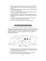
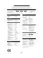
PROSTAR
P H O T O V O LTA I C S Y S T E M C O N T R O L L E R S
OPERATOR’S MANUAL
MODEL RATINGS
PROSTAR-12 PROSTAR-20 PROSTAR-30
Rated PV current
12A
20A
30A
Rated Load current
8A
16A
30A
System voltage:
12 and 24 volts, auto selected
ProStar models
• Standard
included in this
• With LCD meter
manual:
CONTENTS
1.0
2.0
3.0
4.0
5.0
6.0
GENERAL INFORMATION.................................................... 2
QUICK START INSTRUCTIONS ............................................ 3
INDICATORS ...................................................................... 4
3.1 LED Indicators .................................................. 4
3.2 Digital Meter & Disconnect .............................. 5
INSTALLATION INSTRUCTIONS ............................................ 6
4.1 Polarity Protection ............................................ 6
4.2 Installation Procedure ...................................... 7
OPERATION........................................................................ 10
5.1 Controller Operation ........................................ 10
5.2 Controller Functions ........................................ 10
5.3 Inspection and Maintenance ............................ 11
5.4 Troubleshooting................................................ 12
SPECIFICATIONS ................................................................ 15
1.0 GENERAL INFORMATION
Thank you for selecting the ProStar PV controller. The
ProStar is a highly sophisticated controller using advanced
technology and microprocessor control. The battery charging process has been optimized for longer battery life and
improved system performance.
Many functions of the ProStar are unique. Although the
ProStar is very simple to use, please take the time to read
this operator’s manual and become familiar with the controller. This will help you to make full use of the many
advantages the ProStar can provide to your PV system.
PRECAUTIONS “Always Put Safety First”
• Always be very careful when working with batteries. Batteries
can produce explosive hydrogen gas. A short-circuit can pull
thousands of amps from the battery.
2
• Even though the system is only 12 or 24 volts, both the PV
array and battery can contain lethal amounts of electrical
power.
• Do not splash water on the controller, do not allow water to
enter the ventilation slots.
• Do not touch the heatsink. Under certain operating conditions, the heatsink can become hot.
• Always install the controller in a vertical position. Ensure
adequate space for ventilation, and never block the ventilation slots.
• Do not short-circuit the PV array while connected to the
controller. This will damage the controller.
• Do not exceed the current ratings of the controller.
2.0 QUICK START INSTRUCTIONS
This section provides a brief overview of how to get started
using the ProStar controller. However, please review the
entire manual to ensure best performance and years of
trouble-free service.
1. Mount the ProStar to a vertical surface. Allow space above
and below the controller for air flow. The heatsink MUST be
in a vertical (up & down) position.
2. Make sure the PV and load currents will not exceed the
ratings of the ProStar model being installed.
3
3. Connect the BATTERY first. Observe that all LED’s flash in
sequence one time.
4. Connect battery SENSE leads (if utilized). This is recommended if the controller is placed more than 2 to 3 meters
from the battery.
5. Connect the PV (solar array). With sunlight, the green
CHARGING LED will light in 2 minutes.
6. Connect the LOAD. If the LED indicators begin to flash, the
load is shorted. Refer to the detailed installation instructions.
7. The BATTERY TYPE at start-up is sealed (LED on). If the PV
system battery is a flooded type, use a piece of wire to touch
the SELECT PIN to the battery minus terminal to change to
flooded (LED goes off). This must be reset every time the
battery is disconnected.
8. The ProStar will automatically select for a 12 or 24 volt system. If this is a 24 volt system, first check to confirm that the
battery is above 17 volts, and boost-charge the battery if
under 17 volts.
9. Observe the LED indicators. After a few minutes to clear
delays and resets, the LED’s should operate per system conditions as described in the following chart (section 3.1).
10. For effective surge protection, it is recommended that the
negative system conductor be properly grounded.
3.0 INDICATORS
3.1 LED INDICATORS
The ProStar utilizes 5 LED (light emitting diode) indicators
to provide controller and system status information. These
are described in the following table.
INDICATOR
COLOR DESCRIPTION
BATTERY TYPE
Green
ON: Sealed battery type
OFF: Flooded battery type
STATUS
Green
ON: PV array power available
and charging battery
OFF: PV array power is off
4
BATTERY CHARGE Green
ON: Battery near full charge
BATTERY CHARGE Yellow
ON: Battery at middle capacity
(about 35% to 80% SOC)
NOTE: does not indicate
a problem
BATTERY CHARGE
FLASH: Battery at low charge,
warning
ON: Load has been disconnected
All LED’s
Red
SEQUENTIAL FLASH:
Load is short-circuited
High temperature shutdown
High voltage disconnect
Initial battery connection (startup)
(flashes one cycle only)
3.2 DIGITAL METER & MANUAL DISCONNECT
If your model is supplied with the LCD meter, the controller
will include a precision 3-digit meter that displays battery
voltage, PV array current and load current. The meter will
automatically sequence between these 3 parameters. The
3 small green status LED’s will indicate which parameter is
being displayed.
The LCD meter will operate from -30°C to +85°C. The
values displayed are accurate to within a few percent.
However, please note that if the BATTERY SENSE is not
connected, the voltage displayed will be reduced by the
voltage drops in the battery wires.
The red DISCONNECT button will provide an immediate
disconnect of both the PV array and load when pushed
(the button’s red LED turns on). To return the controller to
normal operation, push the button a second time. Note
that restarting the controller with the button will cause the
controller to go through the start-up sequence with the
normal delays and LED indications.
5
4.0 INSTALLATION INSTRUCTIONS
4.1
POLARITY PROTECTION (AND LED INDICATIONS)
CAUTION: Although the ProStar is fully protected from
reversed polarity, the system operator and other
equipment may be at risk when polarities are
reversed. Carefully check each connection and
observe the LED’s to make sure polarity is correct.
CONNECTION POLARITY
RESULT AND LED INDICATION
Battery
Correct
All 5 LED’s will sequence one time.
BATTERY TYPE indicator will remain on
(default is sealed). The green BATTERY
CHARGE indicator will light within 15 seconds, and will then cycle to the correct state.
Battery
Reversed
No LED’s will light. No damage will occur.
Sense
Correct
No additional indications.
Sense
Reversed
If the battery has been connected correctly, there will be sparking at the terminals. If the negative sense lead is connected first, no damage will occur (small
possibility of damage if positive connected first). There will be no indications.
PV Array
Correct
LED’s will light only if the battery has
been connected. During daytime with
battery present, the CHARGING indicator will light after a 2 minute delay.
PV Array
Reversed
No damage will occur. The CHARGING
indicator will not light after the 2 minute
delay.
Load
N/A
If a load short-circuit exists, load will
instantly disconnect to protect the
controller. LED’s will then sequence
to indicate a short.
6
4.2
INSTALLATION PROCEDURE
GENERAL INSTALLATION NOTES:
• The ProStar prevents reverse current leakage at night, so
a blocking diode is not required in the system.
• The ProStar is designed to regulate ONLY PV power. Do
NOT connect to any other type of power generator.
• The ProStar automatically selects 12 or 24 volt setpoints at
battery connection. Do not connect a battery larger than 24
vdc (12 cells) or the controller will be damaged.
• The connector terminals will accept a maximum wire size
of AWG #6 (solid/multistrand) or AWG #8 (fine strand) or a
maximum wire diameter of 5.0 mm. Use a flathead insulated
screwdriver (up to 5 mm).
NOTE: Carefully observe the LED indications at each connection. Per the chart above, the LED’s will indicate
proper polarity and a good connection.
NOTE: Connections may be made in any order. However,
the BATTERY must be connected first for the LED
indicators to operate. The SENSE input will not
power the LED’s.
INSTALLATION STEPS:
1. Inspect the controller for shipping damage. Mount the
ProStar to a vertical surface (4 stainless steel #8 self-tapping
screws are included). Do not install directly over an easily
combustible surface since the heatsink may get hot under
certain operating conditions.
NOTE: Heatsink must be in a vertical (up and down) position.
Allow a minimum of 15 cm (6 inches) space above and below
the controller for air flow. Install in an area protected from
direct rain and extreme temperatures.
If the controller is installed in an enclosure, some ventilation
is recommended. If installed in a sealed enclosure, under
extreme conditions the ProStar may, at times, reach 70ºC
and disconnect the PV array briefly.
2. Confirm that the PV array and loads will not exceed the current ratings of the ProStar model being installed (see chart
on front cover).
7
Multiple ProStar units can be paralleled at the system battery,
but be careful that no PV sub-array exceeds a controller’s
individual current rating.
3. BATTERY (+ and -) Before connecting the battery, check the
open-circuit voltage of the system battery. It must be at least
8 volts for the controller to operate. If your PV system is 24
volts, the battery MUST be over 17 volts, or the controller
will regulate at the 12 volt setpoints. Any battery starting at
less than 11 (or 22) volts should be fully charged before connection to a PV system, or battery life will be significantly
reduced.
NOTE: The battery should be connected first. This will
activate the controller self-protection features,
and will power the LED’s to guide installation
and start-up.
Connect the battery and observe that all 5 LED’s flash in sequence one time. If the LED indicators do not sequence or
the BATTERY TYPE LED does not light, check the battery
polarity.
The green, yellow or red BATTERY CHARGE LED will light
depending on the battery charge state.
4. SENSE (+ and -) Battery sense leads are recommended if the
controller is located more than 2 or 3 meters from the battery. This will avoid voltage drops and improve the control
accuracy. However, if the sense leads are not connected, the
controller will default to BATTERY connections for control.
A smaller wire size can be used for sense (draws less than 1
mA current). Note that the wire entry slots into the case for
SENSE are smaller than the other system power terminals to
prevent mixing the BATTERY and SENSE connections.
5. PV (+ and -) Use these terminals to connect the solar array.
First confirm that the PV modules are wired for the same
voltage as the battery (either 12 or 24 volts).
Use caution, since the PV array will generate power whenever
in sunlight. Also, be careful not to short-circuit the PV array
while connected to the controller, since this will damage the
controller.
There is a 2 minute delay after connection of the PV array
before the controller begins charging. Check that the
8
CHARGING indicator comes on after 2 minutes to confirm
that the PV array has been properly connected.
6. LOAD (+ and -) Turn the load off. Connect the load to
LOAD terminals, and then turn the load on. If the battery is
below the load disconnect voltage, the load will be disconnected (normal LVD). There may be a short delay.
If the load is short-circuited, the controller will instantly
disconnect the load and flash the LED’s in sequence. If this
occurs, remove the load and repair the short. It will then be
necessary to disconnect the BATTERY + wire and reconnect
the battery to reset the ProStar for normal operation (or press
the red DISCONNECT button twice if the LCD meter option
is supplied).
7. The BATTERY TYPE defaults to sealed, and the green LED
should be on. If your battery is a flooded type, use a piece of
wire to touch the SELECT PIN to the BATTERY - (negative)
terminal or to the negative battery post. This will change the
battery charging setpoints from a sealed to a flooded battery.
When the change has been made, the green BATTERY TYPE
LED will turn off.
Check the LED to confirm the change. This SELECT PIN can
be used repeatedly. No damage can occur from touching the
pin to other terminals or parts of the controller. The BATTERY TYPE can be changed between sealed and flooded
any number of times.
NOTE: Remember that flooded batteries must be selected
every time the battery is disconnected, because the
controller will default to sealed at start-up.
Confirm that the proper battery type has been selected by
checking the green LED. No other control setpoints can be
adjusted since they have been factory set for optimum performance.
8. After about 5 minutes, observe all the LED’s. Use the LED
indicator chart in section 3.1 to make sure the controller is
operating normally for system conditions.
9. For safety and effective lightning protection, the negative
conductor of the PV system should be properly grounded.
The ProStar connects the PV-negative, Battery-negative and
Load-negative internally per UL recommendations. No
switching is done in the negative current path.
9
5.0 OPERATION
5.1 CONTROLLER OPERATION
The ProStar is a fully automatic PV system controller that
includes many electronic functions to protect both the controller and the PV system. Battery charging is managed by a
constant-voltage, PWM algorithm that has been optimized
for PV systems.
The only manual tasks performed by the operator are:
a.
b.
c.
d.
e.
Installation (see section 4.0)
Battery type selection (see section 4.2-7)
Disconnect button (with LCD meter, see section 3.2)
Reset if load short-circuits (see section 4.2-6)
Maintenance (see sections 5.3 and 5.4)
5.2 CONTROLLER FUNCTIONS
The PV system operator should become familiar with
the following functions of the ProStar controller. Refer to
Technical Specifications (6.0) for actual setpoints and other
parameter values.
LVD - Low Voltage
Load Disconnect
Automatic load disconnect to protect battery
from deep discharge. Auto reconnect.
Current compensated for high load currents.
Low Voltage Alarm
Red LED flashes at low battery capacity to
warn of possible LVD if discharging continues.
Over Voltage
Protection
If battery voltage rises above the constant
voltage regulation setpoint, the PV array is
disconnected. Auto reconnect.
HVD - High Voltage
Disconnect
Both PV array and load are disconnected
when battery rises to dangerous voltage.
The LED’s flash in sequence. Auto reconnect
as voltage falls.
10
Automatic Safety
Disconnects
• Load Short-Circuit: Instant load
disconnect. The LED’s flash in sequence.
Battery must be disconnected to clear
and reset (see section 4.2-6)
• High Temperature: At very high temperatures, PV array first disconnected, then
the load. The LED’s flash in sequence.
Auto reconnect as temperature falls.
• Emergency: If battery is disconnected,
the PV and load are instantly disconnected for safety and to protect the load.
Temperature
Compensation
Battery charging, equalization, and high
voltage functions are corrected for ambient
temperature variations.
Equalization
Battery charging is automatically boosted
based on low state-of-charge or elapsed
time.
NOTE: Actual charging setpoints of the ProStar controller
are adjusted for temperature, equalizations, and battery type. In addition, many delays are built into the
controller. Remember to consider these factors when
working with the controller.
5.3 INSPECTION AND MAINTENANCE
At least 2 times per year the following inspections and
maintenance are recommended for best controller performance.
1. Confirm that the desired BATTERY TYPE has been selected
(check green LED).
2. Confirm that the current levels of the PV array and load do
not exceed the ProStar ratings.
3. Tighten all the terminals. Inspect for loose, broken, or burnt
wire connections. Be certain no loose stands of wire are
touching other terminals.
4. Check that the controller is securely mounted in a clean,
protected environment.
5. Be certain the ventilation holes are not blocked.
11
6. Inspect for dirt, insects, nests, and corrosion.
7. Check that the controller functions and LED indicators are
correct for the system conditions at that time.
5.4 TROUBLESHOOTING
If something seems wrong with the PV system (for example,
the load is not working or the battery is not charging), then
it may be necessary to troubleshoot the controller. Some
basic troubleshooting procedures are listed below.
•
•
•
•
CAUTIONS:
Troubleshooting should be attempted by qualified
personnel only.
Remember that a battery can cause serious damage if
shorted.
Do not disassemble the ProStar from its case. There are
no user serviceable parts inside the ProStar.
Observe all normal precautions when working with
energized circuitry.
NOTE: There are no internal fuses or circuit-breakers in the
ProStar case. There is nothing inside the case that
can be adjusted, and there are no consummable
parts to replace.
1. BATTERY IS NOT CHARGING
a. Check for proper LED indications on the ProStar. The green
CHARGING LED should be on if it is daytime. One of the
BATTERY CHARGE LED’s should be on. If the ProStar
includes the meter option, check for proper battery voltage
and array current.
b. Check that the proper BATTERY TYPE has been selected.
c. Check that all wire connections in the system are correct and
tight.
d. Measure the PV array output voltage and confirm it is within
normal limits. If the voltage is low or zero, check the connections at the PV array itself. Disconnect the PV from the controller when working on the PV array.
e. Check that the load is not too large.
f. If the BATTERY SENSE terminals are not being used, there
may be excessive voltage drops between the controller and
12
g.
h.
i.
j.
the battery. This will cause undercharging of the battery.
See section 4.2-4.
Check the condition of the battery. Determine if the battery
voltage declines at night with no load. If unable to maintain
its voltage, the battery may be failing.
If all the ProStar LED’s are flashing in sequence, see item
number 4 below.
Check that the controller is operating at the correct system
voltage (12 or 24 vdc), and that the battery has enough voltage (over 8 volts) to operate the controller. If there is any
question, reset the controller by removing the BATTERY +
wire from the terminal and reconnecting it to the controller.
If the battery, PV array and wire connections seem to be satisfactory, and if the ProStar LED indications are not normal
(refer to section 3.1 “LED Indicators”), then the ProStar may
be defective.
NOTE: The controller’s microprocessor should be reset
(restarted) if any of the following conditions seem
to exist:
• The microprocessor latches (locks-up)
• The controller seems to be operating at the wrong
system voltage (12 or 24 volts)
• The battery voltage fell below 8 volts and the
controller cannot automatically restart
• A load short-circuit caused the controller to shutdown
To reset the processor, simply remove the BATTERY +
wire and reconnect it to the controller. With the LCD
meter option, just press the red DISCONNECT button twice. The controller will sequence through it’s
entire start-up routine (See section 4.2).
2. BATTERY VOLTAGE IS TOO HIGH
a. Check the operating conditions to confirm that the voltage
is higher than specifications. Consider the temperature
compensation and automatic equalizations. For example,
a 12 volt flooded battery at 0°C in equalization will be
regulated at about 15.4 volts.
b. Check that the proper BATTERY TYPE has been selected.
c. Check that all wire connections in the system are correct and
tight.
13
d. If there is a problem with high voltage, the controller should
go into the High Voltage Disconnect mode (see section 5.2).
3. LOAD NOT OPERATING PROPERLY
a. Check that the load is turned on. Check that no system fuses
are defective. Check that no system circuit breakers are
tripped. Recall that there are no fuses or circuit breakers
inside the ProStar.
b. Check connections to the load, and other controller and
battery connections.
c. Check for proper LED indications on the ProStar. If the red
BATTERY CHARGE LED is on, the load has been disconnected due to low battery voltage. This is generally a normal
state when the load exceeds the PV array output due to
weather and sunlight conditions.
d. If all LED indicators are flashing in sequence, the load may
be shorted. Determine the cause of the short, repair the
short circuit, and reset the controller (see section 4.2-6).
e. If the ProStar internal temperature is above 80°C, the load
will be disconnected. All LED’s will be flashing in sequence.
Check to ensure for clear airflow around the ProStar and that
nothing is obstructing the vents at the top of the case.
4. LED INDICATORS ARE FLASHING IN SEQUENCE
a. The load may have a short-circuit. Refer to section 4.2-6.
b. The controller may have shutdown due to excessive
temperatures. Refer to 3.e above and section 5.2.
c. The controller may have shutdown due to a High Voltage
Disconnect. See section 5.2 and 2.d above.
5. BATTERY CHARGE RED LED INDICATOR FLASHING
a. This indicates the battery voltage is very low, and the load
may be disconnected soon. Turn off or reduce loads on the
system to allow the battery to recharge. When the battery
capacity increases, the yellow LED indicator will turn on,
followed by the green LED that indicates nearly full charge.
b. If the red LED flashes frequently, the most likely cause is a
load that is too large for the PV array. Another cause is a
defective battery that cannot hold a charge.
14
6.0 TECHNICAL SPECIFICATIONS
MODEL RATINGS
PV current (amps)
Load current (amps)
ProStar-12
ProStar-20
ProStar-30
12
8
20
16
30
30
• All models both 12V
and 24V (automatic
selection)
Note: Current ratings can be exceeded by 25% for up to 5 minutes.
RELIABILITY
MECHANICAL
5-year failure rates at a 90% confidence level
• ProStar-12 .................................... < 0.1%
• ProStar-20 .................................... < 0.1%
• ProStar-30 .................................... 0.4%
• Dimensions: (inches) ........... 6.01 (W) x 4.14 (H) x 2.17 (D)
(mm) ............... 153 (W) x 105 (H) x 55 (D)
• Weight:
(oz) ................. 12
(kg) ................. 0.34
• Wire terminals ..................... Euro-style
Max wire size:
(solid) .............. #6 AWG/16 mm2
(multistrand) ... #6 AWG/10 mm2
(fine strand) .... #8 AWG/10 mm2
Terminal diameter ........... 0.2 inch/5 mm
• Mounting orientation ......... vertical
• Case:
Material ........................ VALOX #310 SEO
Fungicidal resistance ....... ASTM G21-70
Moisture absorption ........ < 0.4%
UL Thermal Index ............ 120°C/140°C
ENVIRONMENTAL
• Operating temperature ................ -40 to +85°C
• Max ambient temperature ........... +60°C
• Storage temperature .................... -55 to +100°C
• Humidity ....................................... 100% (NC)
PERFORMANCE / ELECTRICAL
• Accuracy
12V ........................... +/- 22 mV
24V ........................... +/- 38 mV
• Maximum array voltage ................ 50 V
• Min voltage to operate ................ 8.0 V
• Ground
................................. negative
• Parallel capability ......................... yes
• Self-consumption (tare):
Night
................................. 11 mA
Charging ................................. 12 mA
Load disconnected ................... 10 mA
• Voltage drops:
Maximum: PV/Batt ..................... 0.7 V
Batt/Load ................. 0.4 V
Typical: PV/Batt ..................... 0.5 V
Batt/Load ................. 0.1 V
• Operating life ............................... 15 years
• Noise:
µP protection ........................... all inputs
Output noise pulses ................. < 400 mV
Noise pulse width .................... < 500 nanosec
Radiated noise ......................... < 100 picowatts/Khz
• FET’s:
Rds (on resistance) ................... 0.018 ohm
Pulse rating .............................. 120 A
Junction temp rating ................ 175°C
Operating junction temp ......... 110°C
• µP memory ................................. 2k ROM
• µP clock speed ............................. 2 Mhz
• Transient surge suppressors:
Pulse power rating ................... 1500 watts
Response ................................. < 5 nanosec
• LED’s:
Pulse rate ................................. 300 Hz
Current consumption ............... < 1 mA/LED
ELECTRONIC FUSE / SYSTEM SAFETY
• Load short-circuit ................ Short-circuit is > 10X load
rating for > 5 msec
........................ Load disconnected < 50
microsec
• Emergency disconnect ....... If voltage < 2.4 V, PV/load
disconnected < 0.1 sec
• Reverse polarity .................. All 4 system inputs fully
protected
• High temp shutdown .......... 70°C disconnect PV input
80°C disconnect load
60°C reconnect load
50°C reconnect PV
CONTROL SETPOINTS
12 Volt
Sealed Flooded
• Low volt load disconnect
11.4
11.5
• LVD reconnect
12.5
12.6
• Constant-voltage regulation 14.1
14.3
• Equalization
14.35
14.6
• HVD
15.5
15.5
(24V setpoints are twice 12V values)
CONTROL PARAMETERS
• Charge algorithm ............... constant-voltage
PWM pulse charging
series configuration
• Temp comp coefficient ...... - 5.0 mV/°C/cell (25°C ref)
• LVD current coefficient ....... - 20 mV/amp load
• Auto equalize:
Sealed
........................ 16 days or 11.9/23.8 V
Flooded ........................ 11 days or 12.0/24.0 V
• Temp comp setpoints ........ Regulation, Equalize, HVD
• Software delays .................. LVD = 55 sec; HVD = 7 sec
• Software filtering ................ average 2 inputs/50 µsec
• Measurement rate .............. 37.5 samples/sec
METER DISPLAY
• Type ............................................. LCD
• Display .......................................... 3-digit x .5 inch
• Temp rating .................................. -30 to +85°C
• Voltage accuracy .......................... 0.5%
• Current accuracy .......................... 2.5%
• Status LED’s ................................. 3
• Self-consumption (tare) ................ 8.5 mA
• Manual disconnect ....................... < 100 microsec
Specifications subject to change without notice.
Manufactured in the U.S.A.
15
P.O. BOX 958
OLNEY, MARYLAND 20830 USA
R1- APRIL 1996