1
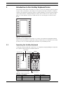
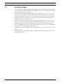
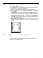
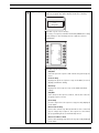
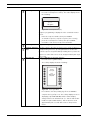
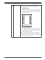
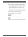
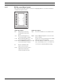
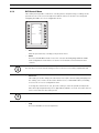
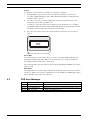
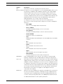
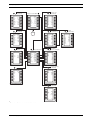
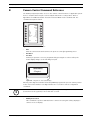
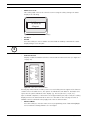
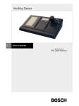
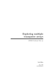
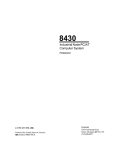
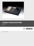
IntuiKey Keyboard
Keyboard
Version 1.93
en
User Manual
IntuiKey Keyboard
Table of Contents | en
iii
Table of Contents
1
Introduction to the IntuiKey Keyboard Series
1
1.1
Operating the IntuiKey Keyboard
1
1.2
The Status Display
2
1.3
The Keypad
3
1.4
The Softkeys and the Softkey Display
3
1.5
The Joystick
4
1.6
Navigating the System with the IntuiKey Keyboard
4
1.6.1
General Guidelines for Navigating the IntuiKey Menus
4
1.6.2
The Product Selection Menu
4
1.6.3
Selecting a Device for Control
5
1.6.4
Easy Switching between Devices
5
1.6.5
Using the Keypad for Numeric Entry (Camera Control)
5
1.6.6
Using the Quick Selection Softscreen Feature
5
1.7
Alarm/Alert/Action Indication
6
2
Controlling Allegiant Series Video Switchers
7
2.1
The Allegiant Main Control Menu
8
2.2
Programming and Controlling Allegiant Functions
8
2.3
Allegiant User Function Menus
15
2.4
Allegiant Error Messages
17
3
Controlling Divar Series Digital Video Recorders
19
3.1
Accessing the Divar Main Control Menu
20
3.2
Programming/Controlling DVR Functions
21
3.2.1
The DVR Main Control Menu
21
3.2.2
DVR On-screen Menu Controls
24
3.2.3
DVR Control Menu
25
3.3
DVR Error Messages
26
4
Controlling System4 Video Multiplexers
27
4.1
Accessing the MUX Main Control Menu
27
4.2
Programming/Controlling MUX Functions
28
4.2.1
Password Entry
28
4.2.2
MUX Main Control Menu Command Descriptions
28
4.3
MUX Error Messages
32
A
IntuiKey Menu Reference
33
B
Camera Control Command Reference
37
C
Keyboard Camera Commands
41
Bosch Security Systems, Inc.
User Manual
F.01U.127.291 | 1.93 | 2009.03
iv
en | Table of Contents
F.01U.127.291 | 1.93 | 2009.03
IntuiKey Keyboard
User Manual
Bosch Security Systems, Inc.
IntuiKey Keyboard
1
Introduction to the IntuiKey Keyboard Series | en
1
Introduction to the IntuiKey Keyboard Series
This manual contains all the information necessary to operate the IntuiKey Keyboard. Step-bystep procedures, illustrations, and sample menus guide you through each phase of IntuiKey
operation. Throughout the manual, you will see sample drawings of each menu as they appear
on the keyboard. These drawings display the softkey text in relation to the Softkey. For the
purposes of this manual, each key is numbered from 1 to 14, using the convention found
below.
Figure 1.1
Softkey Numbering Guide
Following the menu diagram, the function of each key is described in a paragraph indicated
with an icon that identifies the particular softkey. Be aware that some instructions are modelspecific; be sure to read the appropriate information for your IntuiKey model.
1.1
Operating the IntuiKey Keyboard
Learning the IntuiKey Keyboard components is accomplished easily by dividing the keyboard
into separate functional areas as illustrated below:
SoftKey Display
SoftKey Descriptor
Numeric
Entry Cell
Status Display
Monitor Camera
1
Exit
^ Up
1
MUX/DVR
Prod
Zoom
Mon
Shot
Clr
< Left
Right >
v Down
1
2
3
4
5
6
7
8
9
0
Numeric Keypad
SoftKeys
Figure 1.2
Reference
1
2
3
Bosch Security System, Inc.
IntuiKey Components
Description
Softkey Descriptor
Softkeys
Softkey Display
User Manual
Reference
4
5
6
Description
Status Display
Numeric Keypad
Numeric Entry Cell
F.01U.127.291 | 1.93 | 2009.03
2
1.2
en | Introduction to the IntuiKey Keyboard Series
IntuiKey Keyboard
The Status Display
The Status Display changes dynamically to display pertinent information about the keyboard’s
present mode of operation. Typically, its information conveys one of two keyboard operating
modes: Normal Mode or Error Code.
In Normal Mode, the status display provides data pertaining to the present device under
control (e.g. monitor number, camera number, device under control status, etc.). Common
elements in the display for all devices are a product indicator centered on the bottom line of
the display and one or more numeric entry cells. Each numeric entry cell has a title that
describes what the number represents.
When a user operation results in an error, the status display changes to Error Code (see
Section 2.4 Allegiant Error Messages, Page 17, for Allegiant Error Messages, Section 3.3 DVR
Error Messages, Page 26, for Divar Error Messages, and Section 4.3 MUX Error Messages,
Page 32, for MUX Error Messages). The display shows the error number, a short description of
the error, and the present device under control.
The display reverts to Normal Mode either automatically in two seconds (on its own) or when
CLR is pressed.
In Terminal Mode, the third-party software application determines the displayed text via the
IntuiKey display screen.
F.01U.127.291 | 1.93 | 2009.03
User Manual
Bosch Security System, Inc.
IntuiKey Keyboard
1.3
Introduction to the IntuiKey Keyboard Series | en
3
The Keypad
The Keypad includes the five function buttons (located directly below the status display), as
well as the numeric keypad.
PROD displays the keyboard’s Product Selection menu. This function key (in conjunction with
the Softkeys/Softkey Display) selects the device under the control of the keyboard. The
Product Selection menu also provides access to the Keyboard Control menu.
MON functioning depends on the IntuiKey Model and device under control. For KBD-Universal
keyboards, MON allows entry of a Monitor Number when controlling an Allegiant Switcher.
When controlling a DVR or multiplexer, MON toggles between monitors A and B.
CLR clears any numeric entry and the display reverts to Normal Mode.
provides acknowledgement of an external alarm/ alert/action condition. When this condition
is detected, an audible alarm is enabled, and the key flashes red. The key then functions
differently depending on the device presently under keyboard control.
Note: Refer to Section 1.4 The Softkeys and the Softkey Display, Page 3, for additional
information on alarm/alert/action indication and acknowledgement.
SHOT allows selection of camera pre-positions and is also used to assign softkey display
screen numbers. Pressing SHOT twice enters the preposition programming entry mode. If
SHOT is pressed twice inadvertently, press SHOT again to return to the pre-position selection
mode.
i
NOTICE! To avoid inadvertent mode changes, you must hold the SHOT button down for 2
seconds in order to change it to the SET mode.
The Numeric Keypad allows numeric entry (shown in the status display) as required by the
present function. Note that the default state of the Keypad is camera entry (i.e. pressing a
numeric key places that number in the status display under the camera title).
In Terminal Mode, the third-party software application will determine the IntuiKey’s behavior.
1.4
The Softkeys and the Softkey Display
The Softkeys and Softkey Display allow easy and flexible control and programming of system
devices under keyboard control.
The Softkey Buttons are located on either side of the softkey display. Each softkey may have a
special descriptor associated with it that consists of up to three lines of ten characters.
Pressing a softkey initiates the action described by the associated text. The actual on-screen
display may vary depending on the model being controlled.
The Softkey Display associates commands with the softkey buttons. The commands shown in
the display changes depending on the operational mode of the keyboard and previous softkey
selections. Note that the softkey display initially shows a default menu tailored to the device
under control. This initial menu contains softkey functions that represent commonly used
commands, as well as keys that represent links to other command menus.
In Terminal Mode, the third-party software application determines the displayed text via the
IntuiKey display screen.
Bosch Security System, Inc.
User Manual
F.01U.127.291 | 1.93 | 2009.03
4
en | Introduction to the IntuiKey Keyboard Series
1.5
IntuiKey Keyboard
The Joystick
The IntuiKey Joystick provides three levels of system functionality: control of pan/tilt/zoom
for an external camera, navigating the on-screen programming menus of the Allegiant Video
Switchers, AutoDome® Series Cameras and other devices, and playback control when
operating DVR devices. Use of the joystick to control playback of DVR devices is covered later
in this manual.
Moving the joystick in one of eight directions provides pan/tilt control of appropriately
equipped cameras. Rotating the knob in either a clockwise or counterclockwise direction
provides lens zoom control.
Focus and Iris Control, located above and to the right of the joystick, are rocker-style buttons
that provide keyboard control of camera lens focus (near/far) and camera iris function (open/
close).
In Terminal Mode, operating of the Joystick will send an event to the 3rd party software
application which will determine the action.
i
1.6
NOTICE! If power is temporarily interupted to the keyboard while operating the joystick, you
will need to release the joystick and power off/on the keyboard to re-calibrate the joystick
position.
Navigating the System with the IntuiKey Keyboard
Learning basic navigation techniques with the IntuiKey ensures readiness for control of the
system devices. The following procedures are general in nature and may be applied to the
control of various system devices/operating modes.
1.6.1
General Guidelines for Navigating the IntuiKey Menus
The following keys are important for entering and exiting the IntuiKey programming/control
menus:
–
EXIT. This softkey command is located in the upper left corner of each softkey menu. Use
this key to move back one level in the menu structure (complete menu diagrams are
provided in APPENDIX A at the back of this manual).
1.6.2
–
PROD. Press PROD at any time to return directly to the Main Product Selection menu.
–
CLR. Press CLR to clear any numeric entry and revert the display to Normal Mode.
The Product Selection Menu
The Product Selection menu lists the devices that are in communication with the IntuiKey.
When using Divar XF, Divar MR, and Divar Easy up to two (2) devices will be displayed. If using
Divar Series 1 or 2, up to 12 devices can be shown on a single screen. When more than 12
devices are connected, the arrow softkeys at the bottom of the screen can be used to scroll
through the additional menu(s).
The softkey to enter the Keyboard Control menu can always be found at the very end of the
device listings.
Allegiant
ADIM
DVR 1
Unit A
1
DVR 2
Unit B
17
DVR 3
Unit C
33
DVR 4
Unit D
49
Figure 1.3
F.01U.127.291 | 1.93 | 2009.03
DVR 5
Unit E
65
DVR 7
Unit F
97
DVR 8
Unit G
113
DVR 9
Unit H
129
DVR 10
Unit J
145
DVR 11
Unit K
161
Main Product Selection Menu
User Manual
Bosch Security System, Inc.
IntuiKey Keyboard
Introduction to the IntuiKey Keyboard Series | en
5
NOTICE! When the IntuiKey is first connected up to a device, or whenever a new video device
i
is added to an existing system, enter the Product Selection menu and press the PROD key.
The keyboard will initiate a scan of the communication lines and update the list of devices
connected to it.
If communication is ever lost with an existing device, the product name display will indicate
an Off_Line condition. After communication with the device is restored, this message will
disappear.
For multiplexers, the device address number will be shown. For DVRs, the DVR address
number, its name, and the starting camera offset number will be displayed.
1.6.3
Selecting a Device for Control
1.
Press the PROD button to put the keyboard in the Product Selection Mode. The softkey
display shows the Product Selection menu (refer to Figure 1.3).
2.
Press the desired softkey button adjacent to the desired product name in the display.
Upon selection of a system device to be controlled, the keyboard indicates what product
it is controlling by displaying its name (up to 10 characters maximum) at the bottom of
the status display. The softkey display menu also changes to the top level menu
associated with the selected device.
1.6.4
Easy Switching between Devices
Pressing and holding the PROD key for longer than 1 second while using a DVR Series 1 and 2
or multiplexer enters the device address selection mode. Entering the address of a device will
cause the keyboard to switch to that device’s main menu. If the device address does not exist,
an error message will result, and no change will occur.
1.6.5
Using the Keypad for Numeric Entry (Camera Control)
1.
Press a desired numeric key to place the number in the status display under the camera
title.
i
1.6.6
NOTICE! The additional key entries add digits to the RIGHT side of the camera number. If
more than the maximum number of digits allowed for the specific entry is entered, the
leftmost digit is lost, and all other digits promoted.
2.
Leading zeros may be entered but are not required.
3.
Press ENTER to complete numeric entry.
Using the Quick Selection Softscreen Feature
The IntuiKey softkey display screens can be assigned a reference number which can then be
recalled to quickly return to the desired screen.
1.
To assign a number to a softkey display screen, first navigate to the desired screen.
Simultaneously press the digit 0 and ENTER to enter the softkey screen programming
mode. Press SHOT followed by the single digit (0 to 9) that you want to assign to this
screen.
2.
To quickly jump to a previously programmed softkey display screen, simultaneously press
the digit 0 and ENTER. Press the desired softkey display screen number.
NOTICE! Ten (10) softkey numbers are available within a single product category. Softkey
i
screen numbers can only jump between screens within the same product category. If an
existing softkey screen number is assigned to a new softkey screen, the old one is no longer
valid. Assignments remain even if power is lost.
Bosch Security System, Inc.
User Manual
F.01U.127.291 | 1.93 | 2009.03
6
en | Introduction to the IntuiKey Keyboard Series
1.7
IntuiKey Keyboard
Alarm/Alert/Action Indication
When the IntuiKey detects that an alarm/alert/action condition has occurred on the presently
controlled device, the
key flashes red and an audible tone is heard. During alarm
responses, Divar DVRs and System4 multiplexers will also show special icons to represent the
different types of alarm conditions. Contact type alarm conditions will be represented by a
icon, and action alarm conditions will be represented by a
icon. To silence an alarm,
press the Alarm/Alert/Action key.
If the alert occurs on a device that is not presently under control, the product indicator (in the
status display) alternates between the present product designator and the alarmed product,
with the text ALERT added. The present product is displayed for two seconds, while the
alarmed product is displayed for 0.5 seconds.
i
NOTICE! This functionality is not supported when the IntuiKey is operating in Terminal Mode.
F.01U.127.291 | 1.93 | 2009.03
User Manual
Bosch Security System, Inc.
IntuiKey Keyboard
2
Controlling Allegiant Series Video Switchers | en
7
Controlling Allegiant Series Video Switchers
Before you can take control of an Allegiant Video Switcher, you may have to perform a log-on
procedure to gain access to the Allegiant Main Control menu to control the switcher.
Note: This chapter applies to the KBD-Universal Model only.
–
The keyboard generates a short, audible “beep” when first entering the Allegiant log-in
screen. This beep notifies operators that the keyboard is ready to accept user number
and password data. The keyboard may not correctly accept data entered before this
beep.
–
If log-on information is required, the status display requests a USER NUMBER. Enter the
number using the keypad and press ENTER.
–
The status display requests a PASSWORD. Enter the password using the keypad and
press ENTER.
–
If an invalid user number or password is entered, the status display requests the log-on
again.
–
Following a successful log-on, the softkey display shows the Allegiant Main Control menu,
–
If user log-on is not required, the softkey display shows USER LOGGED ON briefly, then
as illustrated in
displays the Allegiant Main Control menu. The menu displayed depends on the camera
display mode, either four-digit or six-digit.
Monitor
Camera
123
Allegiant
1234
Figure 2.1 Status Display in Four-digit Allegiant Mode
Monitor
123
Camera
99 1234
Allegiant
Figure 2.2
Bosch Security System, Inc.
Status Display in Six-digit Allegiant Mode
User Manual
F.01U.127.291 | 1.93 | 2009.03
8
2.1
en | Controlling Allegiant Series Video Switchers
IntuiKey Keyboard
The Allegiant Main Control Menu
To access the Allegiant Main Control menu:
1.
Press PROD to put the keyboard in Product Selection Mode. The keyboard displays the
the Product Selection menu in the softkey display.
2.
3.
Press the Allegiant softkey button. The status display shows the Allegiant mode.
To select a camera, enter a valid 1 to 4 digit camera number using the numeric keypad
and press ENTER.
If the Allegiant is configured to operate in "6-digit Camera ID" mode, up to 6 digits can be
entered. If the new camera is at the same "site" as the current camera, simply enter 1 to
4 camera number digits.
If the desired camera is at a different "site", 5 or 6 digits must be entered. The first and
second digits are the site number and the remaining 4 digits, including any leading zeros
are the camera number at that site.
4.
While in Allegiant mode, keyboard operators can use a convenient “Go Back” feature. To
go back to the previously selected camera, press and hold the CLR key for more than 1
second.
Exit
Device
Lockout
Program
Sequence
Alarm
Control
Camera
Control
User
Functions
Load
Sequence
ADIM
Controls
Hold
Sequence
Start
Sequence
<Previous
<Sequence
<Step
Next >
Sequence>
Step>
Figure 2.3
2.2
User
Log Off
Command
Script
Allegiant Main Control Menu
Programming and Controlling Allegiant Functions
The Allegiant Main Control menu, displayed on the softkey display, uses the softkey buttons to
execute commands or to gain access to other submenus for additional programming/
configuration. Detailed command descriptions follow. Refer to the Allegiant Switcher
Instruction Book for additional information.
F.01U.127.291 | 1.93 | 2009.03
User Manual
Bosch Security System, Inc.
IntuiKey Keyboard
Controlling Allegiant Series Video Switchers | en
Exit
Exits one menu and reverts to the main menu for the particular
Device Lockout
function being programmed/controlled.
Accesses a softkey menu, allowing the locking/unlocking of
9
specified cameras and monitors.
Exit
Monitor
Lock
Monitor
Unlock
Remote
Lock
Remote
Unlock
Figure 2.4 Device Lockout Menu
–
Monitor Lock/Unlock
–
If the monitor to be locked/unlocked is not the present
monitor, press MON on the keypad. Then enter the
monitor number, followed by ENTER.
–
Press the monitor Lock/Unlock softkey.
–
If the monitor is locked, the display shows an ML on the
monitor’s on-screen status display, indicating that the
monitor is locked. If the monitor is unlocked, ML is
removed.
–
Remote Lock/Unlock
–
If the Camera to be locked/unlocked is not the present
camera, enter the camera number followed by ENTER.
–
Press the Remote Lock/Unlock softkey.
–
If the camera is locked, the display shows an RL in the
monitor’s on-screen status display, indicating that the
remote device is locked. If the camera is unlocked, RL is
removed.
To exit the Device Lockout menu press EXIT.
Bosch Security System, Inc.
User Manual
F.01U.127.291 | 1.93 | 2009.03
10
en | Controlling Allegiant Series Video Switchers
Alarm Control
IntuiKey Keyboard
Alarm commands control the system’s automatic video switching
capabilities in response to alarm signals activated in the Allegiant
system. The camera activated by an alarm is normally the same as
the alarm number, but this relationship can be changed using the
optional LTC 8059/00 Master Control Software for Windows® or
the optional LTC 8850/00 Graphical User Interface software
package. These optional software packages even permit up to
four (4) cameras to be alarmed by a single alarm input.
Exit
Arm
Alarm
Arm
All
Alarms
Disarm
All
Alarms
Arm
Monitor
Disarm
Monitor
Figure 2.5 Alarm Control Menu
–
Arm/Disarm Alarm
To arm/disarm an individual alarm on the monitor currently
controlled by the keyboard:
a.
Press the Arm/Disarm Alarm softkey. The status display
changes to the following:
b.
Enter the alarm number to be armed/disarmed, using
c.
Press ENTER.
the numeric keypad.
–
Arm/Disarm All Alarms
To arm/disarm all alarms on the currently controlled monitor,
simply press the Arm/Disarm All Alarms softkey.
–
Arm Monitor
Press the Arm Monitor softkey to arm the monitor currently
controlled by the keyboard, permitting cameras for armed
alarms to automatically display when an alarm occurs.
NOTE: Alarm video appears on a given monitor only if the monitor
is armed and the alarm is armed for that monitor. The on-screen
monitor status display shows MA (Monitor Armed).
–
Disarm Monitor
Pressing the Disarm Monitor softkey disarms the monitor
currently controlled by the keyboard, thus prohibiting the
monitor from responding to alarms.
F.01U.127.291 | 1.93 | 2009.03
User Manual
Bosch Security System, Inc.
IntuiKey Keyboard
Controlling Allegiant Series Video Switchers | en
11
Program Sequence Changes the softkey display and requests entry of a sequence
number to program. The status display shows the following:
---
Alarm#
Allegiant
Figure 2.6 Program Sequence Display
Upon entry of a sequence number followed by ENTER, the softkey
display changes to the following menu to support sequence
programming:
Exit/
Save
Exit/
Run
Previous
Step
Next
Step
Insert
Step
Delete
Current
Step
Delete
from Here
to End
Figure 2.7 Program Sequence Menu
–
Exit/Save
Saves the present sequence and exits the Program Sequence
menu.
–
Previous Step
Displays the previous sequence step on the OSD (on-screen
display) and allows editing.
–
Next Step
Displays the next sequence step on the OSD and allows
editing.
–
Exit/Run
Saves the present sequence, loads it, runs it, then exits the
Program Sequence menu.
–
Insert Step
Inserts a step before the sequence step presently displayed
on the OSD.
–
Delete Current Step
Deletes the current step. Note that if this is done on the first
step of a single-step sequence, the sequence is erased and
the programming mode is automatically exited.
–
Delete from Here to End
Deletes all remaining steps after the step presently displayed
on the OSD.
Bosch Security System, Inc.
User Manual
F.01U.127.291 | 1.93 | 2009.03
12
en | Controlling Allegiant Series Video Switchers
Load Sequence
IntuiKey Keyboard
Enables the loading of a previously programmed sequence.
–
Press the Load Sequence softkey. The status display shows
the following:
---
Sequence?
Allegiant
Figure 2.8 Load Sequence Display
Sequence programming is displayed on the controlled monitor
screen.
–
Enter the sequence number, then press ENTER.
–
To unload a sequence, stop the sequence (if necessary),
press the Load Sequence softkey, then press ENTER.
Hold Sequence
–
Use CLR to clear an incorrectly entered number.
Stops a running sequence.
Previous Sequence Sets the sequence direction to run in reverse. If the sequence is
Step
already running in reverse, pressing this button executes the
previous sequence step immediately. Holding the key causes the
sequence to run in fast reverse mode, at approximately two steps
User Log-off
per second.
Used to LOG OFF the Allegiant Switcher.
–
Press the User Log OFF softkey.
–
The softkey display shows the following:
Allegiant
User Log OFF
Press:
[Enter] to log off
[Clr] to Exit
Figure 2.9 User Log-off Menu
–
Press CLR to clear the pending log-off. Press ENTER to
complete the log-off process. The softkey display reverts to
displaying only USER LOG ON, and the status display
changes back to the default mode (i.e. camera and monitor
numbers replaced with dashes). This mode times out in
approximately two seconds and reverts to the previous
menu.
F.01U.127.291 | 1.93 | 2009.03
User Manual
Bosch Security System, Inc.
IntuiKey Keyboard
Controlling Allegiant Series Video Switchers | en
Command Script
13
Accesses a series of menus, allowing execution of Allegiant script
commands. Refer to the Allegiant Instruction Manual for
additional information.
–
Run Command Script
This function allows the user to execute *STAR commands
from the keyboard. The Allegiant supports over 150,000
commands. Press the Command Script softkey to display the
following softkey menu:
Exit
Run
Script
*Star
Figure 2.10 Command Script Menu
–
Executing Command Scripts
Run a Command Script in one of two ways. Either press the
Run Script softkey (and enter the script number on the
keypad) OR press the * key for the STAR only command (i.e.
Allegiant command script, 0000).
NOTE: The Command Script menu can be customized with
specific scripts and submenus using the optional IntuiKey PC
software package. Refer to the documentation included with the
software for more specific instructions.
Bosch Security System, Inc.
User Manual
F.01U.127.291 | 1.93 | 2009.03
14
en | Controlling Allegiant Series Video Switchers
Camera Control
IntuiKey Keyboard
Displays the camera control softkey menu, allowing the entry of
various camera control commands. Refer to Appendix B at the
back of this manual for details on the camera commands. Access
to certain AutoDome menus and commands may be prohibited by
security features within the camera. Refer to Appendix C for more
User Functions
information.
Accesses a series of five menus allowing single-key selection of all
available Allegiant user functions. Each of the five menus contain
the following common softkeys:
–
Exit (upper left):
Completes any pending user function and exits to the
Allegiant Main Control menu.
–
Previous Menu (lower left):
Displays the previous menu in this series of five. If the
current display is the first menu, Previous Menu displays the
last menu.
–
Enter User Command (upper right):
This function alleviates scrolling through menus. When
pressed, this key prompts for the two-digit Allegiant User
Command number. Familiarity with Allegiant User
Commands and the two-digit command number is required.
Refer to Figure 2.11 on Page 15 for a cross-reference of all
Allegiant User Commands and their respective two (2) digit
function numbers. These function numbers can also be found
in your Allegiant User Manual or on the Allegiant Quick
Reference card.
–
Next Menu (lower right):
Displays the next menu in this series of five. If the current
display is the last menu, Next Menu displays the first menu.
Figure 2.11 on Page 15 shows the menu location and the
associated 2 digit cross reference. For details on the
functionality of these user functions, refer to the Allegiant
Matrix Switcher User Manual.
NOTE: Some User Functions are applicable only to specific
Allegiant models or to newer versions of Allegiant CPU operating
firmware. If an attempt to use a User Function results in an error
message, please consult your Allegiant system manual to
determine if the function is supported in your particular model.
F.01U.127.291 | 1.93 | 2009.03
User Manual
Bosch Security System, Inc.
IntuiKey Keyboard
2.3
Controlling Allegiant Series Video Switchers | en
15
Allegiant User Function Menus
The following illustrations depict the five Allegiant User Function menus:
Enter
User
Command
Exit
Display
User #/
Priority
Change
User
Password
Exit
Select
Time/Date
Format
Default
Monitor
Overlays
Select
Alarm
Response
Set
Alarm
Type
Time Event
Enable/
Disable
<Previous
<Menu
<
Show
Keyboard
Port #
Allegiant
Audio
Display
Battery
Status
CPU Temp
4-6 Digit
Camera ID
<Previous
<Menu
<
Next>
Menu>
>
20
Exit
Adjust
Display
Position
Brightness
Status
Selection
Display
Option
Set
Time
Set
Date
<Previous
<Menu
<
User
Function
Index
Next>
Menu>
>
23
Enter
User
Command
All
Display
Position
All
Display
Brightness
All
Display
Option
Select
Keyboard
Log Off
2-3 Line
Titles
Exit
Next>
Menu>
>
21
Enter
User
Command
Select
Keyboard
Login
Select
Console
Login
Print
Config.
Tables
Print
Sequence
Enter
User
Command
Select
Control
Code FMT
Select
Printer
Verbosity
Printer
Port
Mode
Select
Crosspnt.
Data
DIU
Interface
Camera
Indicator
Set
Controllable
Cameras
R/D
Address
Mode
Cache
Remote
Cameras
Auto
Phase
Adjustment
<Previous
<Menu
<
Next>
Menu>
>
24
Enter
User
Command
Exit
Set
Camera
ID
Set
Monitor
ID
Display
CPU
Version
Reset
System
Vertical
Sync
Adjust
<Previous
<Menu
<
Default
RS232
Console
RS232
Printer
RS232
Alarm
RS232
User
Function
Index
Next>
Menu>
>
22
Figure 2.11
Allegiant User Function Menus
Menu Softkey Function Description
Menu 20
Display User #/Priority
Menu 20
Change User Password
Menu 20
Menu 20
Menu 20
Bosch Security System, Inc.
Show Keyboard Port #
Keyboard Audio
Display Battery Status
User Manual
Allegiant User Function # Access Level
33
Any
10
Any2
2
Any
3
Any
43
Any
F.01U.127.291 | 1.93 | 2009.03
16
en | Controlling Allegiant Series Video Switchers
IntuiKey Keyboard
Menu Softkey Function Description
Menu 20
CPU Temp
Menu 20
4-6 Digit Camera ID
Menu 21
Adjust Display Position
Allegiant User Function # Access Level
45
Any
47
12
4
1-71
Menu 21
Brightness/Status Selection
5
1-71
Menu 21
Display Options
6
1-71
Menu 21
Set Time
7
1-71
Menu 21
Set Date
8
1-71
Menu 21
All Display Position
24
1-71
Menu 21
All Display Brightness/Status
25
1-71
Menu 21
All Display Option
26
1-71
Menu 21
Select Keyboard Logoff
42
12
Menu 21
2-3 Line Titles
46
Menu 22
Menu 22
Menu 22
Menu 22
Set Camera ID Title
Set Monitor ID Title
Display CPU Version
Reset System
9
17
23
15
12
1
1
Any
Menu 22
Vertical Sync Adjust
40
12
Menu 22
Default RS-232
29
12
Menu 22
Console RS-232
30
12
Menu 22
(select controller RS-232–8900)
Printer RS-232
31
12
Menu 22
(select controller RS-232–8900)
Alarm RS-232
32
Menu 22
Menu 23
Menu 23
Menu 23
User Function Index
Select Time/Date Format
Default Monitor Overlays
Select Alarm Response
99
11
12
19
12
Any
1
1
Menu 23
Set Alarm Monitor Type
21
Menu 23
Menu 23
Time Event Enable/Disable
Select Keyboard Login
16
27
Menu 23
Select Console Login
28
Menu 23
Menu 23
Menu 23
Menu 24
Print Configuration Tables
Print Sequence Tables
User Function Index
Select Control Code Format
13
18
99
22
Menu 24
Select Printer Verbosity
20
12
Menu 24
Printer Port Mode
38
Menu 24
Menu 24
Select Crosspoint Data
DIU Interface
36
39
12
1
Menu 24
Menu 24
Menu 24
Camera Indicator
Set Controllable Cameras
R/D Address Mode
34
35
37
Menu 24
Cache Remote Cameras
41
12
Menu 24
Auto Phase Adjustment
44
12
12
12
12
1
12
12
1
1
Any
12
12
1
1
12
Notes:
1.
When using LTC 8900 systems, the access levels required are 1 to 63.
2.
Password is required to change this setting.
F.01U.127.291 | 1.93 | 2009.03
User Manual
Bosch Security System, Inc.
IntuiKey Keyboard
2.4
Error
Error 01
Controlling Allegiant Series Video Switchers | en
17
Allegiant Error Messages
Name
Invalid Camera Request
Description
The camera number entered from the keyboard does not exist. If
using the optional LTC 8059/00 Master Control Software or the LTC
8850/00 Graphical User Interface Software, ensure that the number
exists in the Camera Identification table. Download the table to be
Error 02
Error 03
Invalid Monitor Request
Remote Device Locked by User#
sure.
The monitor number entered from the keyboard does not exist.
The remote device requested cannot be controlled, because it is
locked by a user with equal or higher priority. Check with the other
users or request that a higher priority user unlock the remote
Error 04
Monitor Locked by User#
device.
The monitor requested cannot be accessed, because it is locked by
a user with equal or higher priority. Check with the other users or
Error 05
Error 06
Error 10
Remote Device Access Restricted
Monitor Access Restricted
Access Denied
request that a higher priority user unlock the monitor.
Remote locked out by Remote Lock Out table.
Monitor locked out by Monitor Lock Out table.
A function was requested for which the user priority is too low. Only
a Priority 2 user or a supervisor with Priority 1 may access this
Error 11
Access Denied
function.
A function was requested for which the user priority is too low. Only
Error 15
Invalid User Function
a supervisor with Priority 1 may access this function.
The function number requested from the keyboard is invalid. Refer
to the User Function table for a listing of valid user function
Error 20
Acknowledge Denied
numbers.
The ACKNOWLEDGE button was pressed by a user without the
Error 21
Incorrect Acknowledge
authority to acknowledge alarms.
In order to properly acknowledge an alarm event, the keyboard
Error 22
Acknowledge Disabled
must be switched to a monitor that is displaying the alarms.
Alarms on this monitor cannot be acknowledged, because that
Error 23
Camera not in Alarm
capability has been disabled by the system programmer.
The camera displayed on the monitor is not an alarm video; only
Error 24
Keyboard Not Enabled for
alarm-generated video can be acknowledged.
This keyboard may not acknowledge alarm video on this monitor; it
Error 25
Acknowledge
Alarm Switcher Running
has been disabled by the system programmer.
Alarm video may only be acknowledged if the alarm switcher is not
Error 50
Sequence Not Available
running; press HOLD to stop the switcher.
The user attempted to load a switcher sequence that does not exist.
This is a good way to determine, from the keyboard, which
sequence numbers are unused when desiring to add one. A request
was made to load an ABSOLUTE type sequence, without the
keyboard being on one of the monitors in that sequence. Because
inadvertent loading of monitors should be avoided, the user is
required to switch his keyboard to one of the monitors used by the
sequence. The PROGRAM mode may be used to review which
Error 52
Sequence Request
monitors are used in the sequence.
A request was made to load a RELATIVE type sequence on a monitor
number that is too high; the monitors used by the sequence would
extend past the highest monitor. Try switching to a lower monitor
number before loading the sequence.
Bosch Security System, Inc.
User Manual
F.01U.127.291 | 1.93 | 2009.03
18
en | Controlling Allegiant Series Video Switchers
IntuiKey Keyboard
Error
Error 53
Name
Switcher Empty
Description
The user has attempted to control a sequence using the NEXT,
Error 55
SEQUENCE Priority
PREV, RUN, or HOLD keys, without there being a sequence loaded.
The switcher sequence being requested or cleared requires
monitors that are in use by a user of equal or higher priority.
Contact a user with higher priority or have the system administrator
Error 56
SEQUENCE Request
clear the monitors in question.
The user has attempted to load a sequence that is being edited in
the PROGRAM mode. Once editing is complete, the sequence may
Error 58
SEQUENCE Request
be loaded.
The sequence being requested is a relative sequence, and the user
Error 60
PROGRAM Request
is only permitted access to absolute sequences.
The user has attempted to program a sequence that is currently
running. The sequence must first be stopped before any editing can
Error 62
PROGRAM Request
be performed.
The user has attempted to program a new sequence when the
sequence memory space has been depleted. Delete unused
Error 63
Error 70
PROGRAM Request
Monitor No Allocated to Group
sequences, then program the new sequence.
Another user is already programming a sequence on this monitor.
This monitor cannot be used for alarm operations; it has not been
Error 71
Step Monitor Required
designated as alarm-capable by the system programmer.
A group of alarm monitors may not have an armed Review (display)
Error 78
Must Enter Alarm Number
monitor without having armed Step (sequence) monitors.
A specific alarm number must be entered when arming or disarming
Error 80
Trunk Not Available
an alarm.
An attempt was made to access a remote camera connected to a
Error 81
Satellite Trunk Seized
satellite system, but no unused trunk lines are currently available.
The camera currently viewed has changed because an operator with
a higher priority has selected a different camera that seized the
Error 89
Internal Stack Error
trunk line from the satellite.
A stack overflow within the system has occurred. Report this to the
Error 90
Keyboard Entry Undefined
manufacturer.
The keyboard entry is not defined. Check the appropriate section of
Error 92
Keyboard Entry Out of Range
the instruction manual for the desired operation and try again.
The data entered for a valid command was not in the permissible
range. Check the appropriate section of the instruction manual for
Error 94
Keyboard Entry Invalid
acceptable ranges for the command in question and try again.
An invalid character was received from the keyboard. Usually this
indicates a communications error. Verify that the keyboard-to-
Error 95
Keyboard Entry Incomplete
system cable is not producing an intermittent connection.
The control sequence sent from the keyboard was incomplete.
Usually this indicates a communications error. Verify that the
keyboard-to-system cable is not producing an intermittent
Error 96
* (STAR) Undefined
Error 128 No Communications
F.01U.127.291 | 1.93 | 2009.03
connection.
The * key has been pressed, but there is no definition for this
button.
The keyboard cannot communicate with the Allegiant.
User Manual
Bosch Security System, Inc.
IntuiKey Keyboard
3
Controlling Divar Series Digital Video Recorders | en
19
Controlling Divar Series Digital Video Recorders
This section applies to the KBD-Universal and KBD-Digital models.
NOTE: Depending on the model of the Divar, some features described below may not be
supported. See the table below for supported software features by Divar model.
Supported Software Features
Software Features
Divar
Divar Easy
Divar MR
Divar XF
Full Screen
Y
Y
Y
Y
Quad Screen
Y
Y
Y
Y
Multi Screen
Y
Y
Y
Y
Select Cameo Segment
Y
Y
Y
Y
Sequence
Y
Y
Y
Y
Zoom
Y
Y
Y (Full Screen)
Y
Search
Y
Y
Y
Y
–
Up
Y
Y
Y
Y
–
Left
Y
Y
Y
Y
–
Down
Y
Y
Y
Y
–
F1
Y
Y
Y (Zoom)
N
–
Escape
Y
Y
Y
Y
–
Help
Y
Y
N
N
–
Right
Y
Y
Y
Y
–
Down
Y
Y
Y
Y
–
F2
Y
Y
Y (Play)
N
–
Select
Y
Y
Y
Y
Play
Y
Y
Y
Y
Fast Forward
Y
Y
Y
Y
Reverse Play
Y
Y
Y
Y
Live
Y
Y
Y
Y
Freeze
Y
Y
N
Y
Instant Play
Y
Y
Y
Y
Camera Control
Y
Y
Y
Y
–
Set Shot
Y
Y
Y
Y
–
Modify Preset Tour
Y
Y
Y
Y
–
Add Scene to Tour
Y
Y
Y
Y
–
Aux On
Y
Y
Y
Y
–
Camera Functions
Y
Y
Y
Y
–
Advanced Menu
Y
Y
Y
Y
–
Show Shot
Y
Y
Y
Y
–
Preset Scene Control
Y
Y
Y
Y
–
Remove Scene from Tour
Y
Y
Y
Y
–
Aux Off
Y
Y
Y
Y
DVR Control
Y
Y
Y
Y
–
Y
Y
Y
Y
Bosch Security System, Inc.
Menu
User Manual
F.01U.127.291 | 1.93 | 2009.03
20
en | Controlling Divar Series Digital Video Recorders
IntuiKey Keyboard
Software Features
3.1
Divar
Divar Easy
Divar MR
Divar XF
–
Up
Y
Y
Y
Y
–
Left
Y
Y
Y
Y
–
Down
Y
Y
Y
Y
–
F1
Y
Y
N
N
–
Escape
Y
Y
Y
Y
–
Help
Y
Y
N
Y
–
Right
Y
Y
Y
Y
–
Down
Y
Y
Y
Y
–
F2
Y
Y
N
N
–
Select
Y
Y
Y
Y
User Level
Y
Y
Y
Y
Help
Y
Y
N
Y
Protect
Y
N
N
N
Select DVR
Y
N
N
Y
DVR (Keyboard) Audio
Y
Y
Y
Y
Accessing the Divar Main Control Menu
1.
Press PROD to put the keyboard in the Product Selection Mode. The softkey display
shows the Product Selection Menu. Depending on the number of DVRs that are
connected to the IntuiKey, the list may show a single device name or up to 32 device
names spanning three (3) menu screens when using Divar Series 1 and 2.
2.
Press the softkey button adjacent to the desired DVR device name in the display. The
softkey display menu will change to the top level menu associated with the device.
The status display changes to display the following:
NOTICE! If you are already in a product sub-menu, and multiple products are connected to the
i
IntuiKey, the keyboard provides a means for easy switching between the devices. Press and
hold the PROD key for longer than one (1) second to enter the device address selection mode.
Enter the address of the desired device to make the keyboard immediately switch to that
device’s main menu.
3.
The status display shows the DVR mode display.
Rec
Play
Seq
MONA Zoom
ALM 13
Figure 3.1
Camera
12
DVR#01
Status Display in Divar Mode
The DVR mode is shown on the keyboard status display and provides the following indicators:
–
SEQ – Indicates that the DVR is running a sequence.
–
MON A/B – Indicates which DVR monitor is currently under control. It toggles between
MON A and MON B for each press of the MON key.
F.01U.127.291 | 1.93 | 2009.03
User Manual
Bosch Security System, Inc.
IntuiKey Keyboard
i
Controlling Divar Series Digital Video Recorders | en
21
NOTICE! Keyboard access to MONB must be enabled within the Divar menus. See the Divar
manual for details.
–
Indicates that the DVR is in an ACTION alarm mode.
–
Indicates that the DVR is in a contact activated alarm mode.
–
REC – Indicates that the DVR is currently recording.
–
PLAY – Indicates that the DVR is in a replay mode.
–
ZOOM – Indicates that the DVR is displaying a zoomed image.
–
ALM xx – Indicates that a device connected to the IntuiKey with address number xx is
currently in alarm. The IntuiKey’s alarm button will light and the keyboard will begin to
beep.
NOTICE! While in DVR Control Code, the product title continuously displays the programmed
i
device name. The numeric entry field is used to enter numeric values needed to control the
DVR (i.e. camera number, DVR number, shot number, etc.). Above the numeric entry field is a
title displaying the DVR’s current mode (i.e. cameo, camera entry, menu mode, or numeric
entry).
4.
The softkey display shows the DVR Main Control menu.
Exit
Search
Full
Screen
Play
Quad
Screen
Live
Multi
Screen
Select
Cameo
Segment
Freeze
Instant
Play
Sequence
Camera
Control
Zoom
DVR
Control
Figure 3.2 Divar DVR Main Control Menu
3.2
Programming/Controlling DVR Functions
3.2.1
The DVR Main Control Menu
The DVR Main Control menu uses softkey buttons to execute commands or to gain access to
other submenus for additional programming/configuration.
Detailed command descriptions follow. Refer to the Divar Instruction Book for additional
information.
–
Exit
Exits one menu and returns to the main menu for the particular function being
programmed.
–
Full
Select Full Screen Camera Mode by pressing the Full Screen softkey. The camera
currently selected by the keyboard will be displayed in full screen on the monitor.
NOTE: For the Divar MR, PTZ control is only available when in full screen mode.
Bosch Security System, Inc.
User Manual
F.01U.127.291 | 1.93 | 2009.03
22
en | Controlling Divar Series Digital Video Recorders
–
IntuiKey Keyboard
Quad Screen
Divides the screen into four separate areas. Enable Quad Screen Mode by pressing the
Quad Screen key once. Pressing the key additional times cycles through available viewing
configurations.
–
Multi Screen
Enables multiscreen displays. The capabilities and user setup of the DVR model under
control determine the available configurations.
NOTE:
1) Pressing the Multiscreen softkey multiple times will cycle through the possible menu
selections.
2) For the Divar MR, the joystick only controls cameo segment selection in this mode.
–
Select Cameo Segment
When in Multi or Quad Mode, the screen area where a camera is displayed is called a
cameo. Press the Cameo softkey to enter the cameo selection mode. In this mode, the
joystick is used to select which cameo window will be under control of the keyboard.
Entering a number into the keyboard while in this mode will cause the camera to appear
in the currently selected cameo window. Cameras may be assigned to any selected
cameo, and may be changed as often as required. The IntuiKey’s numeric entry field title
will change to cameo while the DVR is in this mode. Press the cameo softkey again to exit
the mode.
–
Sequence
Runs a previously programmed camera sequence.
–
Zoom
Press the Zoom softkey to enlarge the active camera display. The keyboard will change to
the following submenu for control of the zoom functions:
NOTE:
1) Different levels of the zoom function (e.g. X2, X4, normal) are available by repeatedly
pressing the Zoom softkey.
2) If Zoom softkey is pressed while in multi-screen mode, the currently selected camera
will be changed to full screen view.
Exit
^ Up
Zoom
< Left
Right >
v Down
Figure 3.3
–
Zoom Menu
Search
Places the DVR into the on-screen search mode and accesses a DVR softscreen menu
allowing selection of various search criteria. Refer to Section 5.2.2 for details on menu
functions and controls.
F.01U.127.291 | 1.93 | 2009.03
User Manual
Bosch Security System, Inc.
IntuiKey Keyboard
Controlling Divar Series Digital Video Recorders | en
–
23
Play
Activates DVR playback mode and displays the PLAY indicator in the IntuiKey status
display. Press the softkey again to cancel the playback mode. While in the Playback
mode, the joystick functions as follows:
a.
Move joystick forward or rotate the joystick knob in the clockwise direction to put
the DVR into forward playback mode. The further the joystick is moved or rotated,
the faster the playback will occur.
b.
c.
Move joystick backwards (towards operator) to place DVR in freeze mode.
If paused, move the joystick to the right or rotate the joystick knob in the clockwise
direction to frame advance the image. Move the joystick to the left or rotate the
joystick in the counterclockwise direction to frame reverse the image. The further
the joystick is rotated or moved to the right or left, the faster the image will change.
–
Live
Pressing the Live Softkey places the DVR into the live viewing mode.
–
Freeze
Freezes the currently selected camera image. Press FREEZE again to release the freeze
mode. Changing the display screen mode releases the freeze mode.
–
Instant Play
Activates the DVR playback of the last minute recording for the selected camera.
–
Camera Control
Displays the Camera Control softkey menu, allowing entry of various camera control
commands. Refer to Appendix B at the back of this manual for details of the Camera
Commands.
–
DVR Control
Accesses the DVR Control menu allowing selection of DVR devices and controls for
navigation of device on-screen menus. Refer to Section 3.2.3 DVR Control Menu, Page 25,
for details on menu functions.
Bosch Security System, Inc.
User Manual
F.01U.127.291 | 1.93 | 2009.03
24
en | Controlling Divar Series Digital Video Recorders
3.2.2
IntuiKey Keyboard
DVR On-screen Menu Controls
This softkey menu provides various controls for navigating DVR on-screen menus. Detailed
command descriptions follow.
Exit
Help
^ Up
^ Up
< Left
Right >
v Down
v Down
F1
F2
Escape
Figure 3.4
Select
Divar DVR Menu Control
Softkey Description
Exit
Exits the present menu,
Softkey Description
Help
Accesses the DVR’s on-screen HELP menu.
reverting to the previous
^ Up
menu.
Moves UP through the on-
< Left
screen menu items or values.
Moves LEFT through the on- F2
Right >
Moves RIGHT through the on-screen menu
items or values.
Used to select a specific function associated
screen menu items or values.
with an on-screen menu option.
v Down Moves DOWN through the on- Escape Press this button to return to the previous
screen menu items or values.
level, exit the Help screen, or to exit the onscreen menu completely without saving.
F1
Restores defaults in the
Select
active on-screen menu.
Selects an on-screen menu or
submenu item and saves
selections made in menus.
F.01U.127.291 | 1.93 | 2009.03
User Manual
Bosch Security System, Inc.
IntuiKey Keyboard
3.2.3
Controlling Divar Series Digital Video Recorders | en
25
DVR Control Menu
This softkey menu provides controls for selecting devices and protecting recordings. It also
provides access to the on-screen Help menu and the softscreen menu for accessing and
navigating the DVR’s on-screen configuration menu.
Exit
Menu
Help
Protect
Select
DVR
User Level
Figure 3.5
–
Divar
Audio
Divar DVR Control Menu
Exit
Exits the present menu, reverting to the previous menu.
–
Menu
Accesses the DVR Menu Control screen for selection and navigating within the DVR’s
main configuration menu. Refer to Section 5.2.2 for details on menu functions and
controls.
i
NOTICE! Access to this menu is available only when the User Level is set to FULL ACCESS. If
the current access level must be changed, refer to the User Level softkey explained below.
–
User Level
This softkey is used to change the current User Level. (The current setting is displayed on
the softkey.) User Levels can be used to limit access to certain DVR features, including
access to the on-screen configuration menu.
To change the current User Level, press the softkey to enter the password entry mode.
Enter the keyboard password (refer to Appendix C) within 2 seconds. Select the desired
User Level as listed on the softkey menu.
i
NOTICE! The selected User Level applies to all DVR devices connected to the IntuiKey.
–
Help
Accesses the DVR’s on-screen Help menu.
Bosch Security System, Inc.
User Manual
F.01U.127.291 | 1.93 | 2009.03
26
en | Controlling Divar Series Digital Video Recorders
–
IntuiKey Keyboard
Protect
It is possible to mark a video recording so it cannot be overwritten.
a.
During playback, press the Protect key to mark the beginning of a protected
recording. Playback will pause and a dialog window will appear, showing the time
and date of this selection.
b.
Press the Select key to continue playing the video that you wish to protect. The
c.
To mark the end of the protected recording, press the Product key a second time.
Escape key cancels and exits this mode.
The playback will pause and a dialog window will appear showing the time and date
of both the start and end times of the protected recording.
d.
Press the Select key to protect the marked video from deletion. Press Escape to
cancel.
Address
-DVR
Figure 3.6 DVR Address Status Display
–
Select DVR
Press this button to select another device to control. The status display will change to
display the following: Enter the address of the desired device to make the keyboard
immediately switch to that device’s main menu.
This softkey provides the same function as pressing and holding the PROD key for longer
than 1 second.
–
Divar Audio
This toggle button is used to enable or disable the keyboard audio beeper that sounds in
response to DVR error messages or alarm/action events. Enabling or disabling this option
affects all DVRs connected to the keyboard.
3.3
DVR Error Messages
Error
Error 1
Error 2
Error 3
Error 4
F.01U.127.291 | 1.93 | 2009.03
Name
No Communication
Invalid Keyboard Entry
Invalid DVR Number
DVR Not Found
Description
The keyboard cannot communicate with the DVR.
An invalid number has been entered on the keyboard.
A DVR number less than 1 or greater than 30 was entered.
No DVRs found during search.
User Manual
Bosch Security System, Inc.
IntuiKey Keyboard
4
Controlling System4 Video Multiplexers | en
27
Controlling System4 Video Multiplexers
This section applies to KBD-Universal and KBD-Digital Models.
4.1
Accessing the MUX Main Control Menu
1.
Press PROD to put the keyboard in the Product Selection Mode. The softkey display
shows the Product Selection menu. Depending on the number of devices that are
connected to the IntuiKey, the list may show up to 32 total devices spanning 3 menu
screens.
2.
Press the softkey button adjacent to the desired multiplexer in the display. The softkey
display menu will change to the top level menu associated with the device.
NOTICE! If you are already in a product sub-menu, and multiple products are connected to the
i
IntuiKey, the keyboard provides a means for easy switching between the devices. Press and
hold the PROD key for longer than 1 second to enter the device address selection mode. Enter
the address of the desired device to make the keyboard immediately switch to that device’s
main menu.
3.
The status display shows the MUX mode display.
Rec
VCR
Play
Seq
MONA Zoom
ALM 13
Camera
12
MUX#01
Figure 4.1 System4 Mode Status Display
Display Description
VCR
Indicates that the multiplexer is in a VCR test mode (routing the VCR video being
recorded to the monitor).
SEQ
Indicates that the multiplexer is running a sequence.
MONA/B Indicates which multiplexer monitor is currently under control. It toggles between
MONA and MONB for each press of the MON key.
Indicates that the multiplexer is in an action alarm mode.
Indicates that the multiplexer is in a contact activated alarm mode.
REC
PLAY
ZOOM
ALM xx
Indicates that the VCR is currently recording.
Indicates that the multiplexer is displaying a videotape replay.
Indicates that the multiplexer is displaying a zoomed image.
Indicates that a device connected to the IntuiKey, with address number xx is in
alarm. The IntuiKey’s ALARM button light and the keyboard begins to beep.
NOTICE! While in multiplexer control mode, the product title continuously displays MUX #—
i
(where the dash represents the multiplexer number). The numeric entry cell is used to enter
numeric values needed to control the multiplexer (i.e. camera number, allplex number, shot
number, etc.). Above the numeric entry cell is a title displaying the multiplexer’s current mode
(i.e. cameo, camera entry, or menu mode).
4.
Bosch Security System, Inc.
The softkey display show the MUX Main Control menu.
User Manual
F.01U.127.291 | 1.93 | 2009.03
28
en | Controlling System4 Video Multiplexers
IntuiKey Keyboard
4.2
Programming/Controlling MUX Functions
4.2.1
Password Entry
If a password is required by the multiplexer on-screen display, you must press ENTER after
each number entered for the password (e.g. if the password is 1-2-3-4, you then press 1, then
ENTER, 2, then ENTER, etc.).
Exit
Play
Quad
Screen
ZOOM
Multi
Screen
Select
Cameo
Segment
Freeze
Recorder
Controls
Sequence
Camera
Control
Toggle
VCR
Text Mode
MUX
Control
Figure 4.2
4.2.2
Record
Full
Screen
System4 MUX Main Control Menu
MUX Main Control Menu Command Descriptions
The MUX Main Control menu, displayed on the softkey display, uses the softkey buttons to
execute commands or to gain access to other submenus for additional programming/
configuration. Detailed command descriptions follow. Refer to the Multiplexer Instruction Book
for additional information.
Exit
Exits one menu and returns to the main menu for the particular function being programmed.
Full Screen
Select Full Screen Camera Mode by pressing the Full Screen softkey. The camera currently
selected by the keyboard will be displayed in full screen on the monitor.
Quad Screen
Divides the screen into four separate areas. Enable Quad Screen Mode by pressing the Quad
Screen key once. Pressing the key additional times cycles through different viewing
configurations.
Multi Screen
Enables multiscreen displays. The capabilities of the multiplexer model under control
determine the available configurations.
i
–
6-channel: 5+1
–
9-channel: 4+3, 3x3
–
16-channel: 4+3, 8+2, 12+1, 3x3, and 4x4
NOTICE! Pressing the multiscreen softkey multiple times cycles through the possible
selections.
F.01U.127.291 | 1.93 | 2009.03
User Manual
Bosch Security System, Inc.
IntuiKey Keyboard
Controlling System4 Video Multiplexers | en
29
Select Cameo Segment
When in Multi or Quad Mode, the screen area where a camera is displayed is called a cameo.
Press the Cameo softkey to enter the cameo selection mode. In this mode, joystick is used to
select which cameo window will be under control of the keyboard. Entering a number into the
keyboard while in this mode will cause the camera to appear in the currently selected cameo
window. Cameras may be assigned to any selected cameo, and may be changed as often as
required. The Intuikey’s numeric entry field title will change to Cameo while the DVR is in this
Mode. Press the Cameo softkey again to exit the mode.
i
NOTICE! The multiplexer function of Assigning All Cameras is provided by an additional
softkey on the MUX Main Control menu. Press this key to activate this function.
Sequence
Runs a previously programmed camera sequence.
Toggle VCR Test Mode
Enables/disables the multiplexer’s VCR test mode. When in VCR test mode, the IntuiKey
status display shows the VCR icon.
Record
Activates VCR record mode and displays the REC indicator in the IntuiKey status display.
Press the softkey again to disable the record mode.
Play
Activates VCR play mode and displays the PLAY indicator in the IntuiKey status display. Press
the softkey again to disable the play mode.
Zoom
Enlarges the active camera display. Selection of any other camera displays that camera in full
screen enlarged mode. Press the Zoom softkey to show the following submenu for control of
the zoom function.
Exit
^ Up
Zoom
< Left
Right >
v Down
Figure 4.3
MUX Zoom Menu
Different levels of the zoom function (e.g. x2, x4) may be available depending on the
multiplexer model.
Freeze
Holds the selected camera picture on either full screen or cameo. The currently selected
camera image freezes, and FREEZE is displayed on the monitor screen. Press FREEZE again to
release the freeze mode. Freeze a different camera image by selecting another camera with
the camera keys and pressing FREEZE again. Changing the display screen mode releases the
freeze mode from all cameos.
Bosch Security System, Inc.
User Manual
F.01U.127.291 | 1.93 | 2009.03
30
en | Controlling System4 Video Multiplexers
IntuiKey Keyboard
Recorder Controls
Accesses the DVR1/VCR Control softkey menu, allowing selections for control of either a
DVR1 Series digital recorder or a conventional VCR. Additional menus are displayed for
control of the selected device.
DVR1
Controls
Exit
VCR
Controls
Figure 4.4
Recorder Control Menu
Camera Control
Displays the Camera Control softkey menu, allowing
entry of various camera control
commands. Refer to Appendix B at the back of this manual for details on the Camera
Commands.
MUX Control
Accesses a menu allowing control of additional multiplexer functions.
Exit
On-screen
Menu
Quick
Keys
Find
MUXes
Select
MUX
User Level
MUX
Audio
Figure 4.5
F.01U.127.291 | 1.93 | 2009.03
MUX Control Submenu
User Manual
Bosch Security System, Inc.
IntuiKey Keyboard
Controlling System4 Video Multiplexers | en
31
Softkey
Description
Exit
Exits the present menu, reverting to the previous menu.
On-screen Menu Provides access to the multiplexer’s on-screen display (OSD), if the access
level has been enabled to FULL ACCESS (otherwise, the softkey display
indicates that the present user level is not high enough for this level of
access). If the current user level does not allow the operation, a warning
message is displayed, and control reverts to the MUX Control submenu. The
warning message clears and reverts to the MUX main control menu in
approximately two (2) seconds or after pressing CLR.
To change the access level, refer to the User Level softkey below.
The on-screen control menu provides softkey access for these multiplexer
functions:
–
Exit: ZOOM
Exits to one level higher when in menu mode.
–
Choose: SELECT
Used when the OSD prompts to choose a selection.
–
Save: SELECT
Used when the OSD prompts to save the current selections.
–
Default: FREEZE
Changes an entry to its default state.
–
Help
Displays the MUX’s internal help file associated with the present OSD
selection.
–
Up ^
Moves the OSD cursor up one line.
–
Down v
Moves the OSD cursor down one line.
–
< Left
Moves the OSD cursor to the left one position.
–
Right >
Moves the OSD cursor to the right one position.
–
Enable/Disable
Find MUXes
Used in Set Action Zones in the Action Setup menu.
Polls each MUX address for a response. If a response is found, an ON
User Level
indicator is displayed next to the MUX address. Exit by pressing any key.
This softkey is used to change the current User Level. (The current setting is
displayed on the softkey.) User Levels can be used to limit access to certain
multiplexer features, including access to the on-screen configuration menu.
To change the current User Level, press the softkey to enter the password
entry mode. Enter the keyboard password (refer to Appendix C) within two
(2) seconds. Select the desired User Level, as listed on the softkey menu.
Note that the selected User Level applies to all multiplexer devices
Quick Keys
connected to the IntuiKey.
Allows access to the multiplexer’s quick key commands. If the current user
level does not allow the operation, a warning message is displayed, then
clears and reverts to the MUX main control menu (approximately two (2)
seconds or after pressing CLR). Refer to the Multiplexer Instruction Book
for additional information on the quick key functions.
Bosch Security System, Inc.
User Manual
F.01U.127.291 | 1.93 | 2009.03
32
en | Controlling System4 Video Multiplexers
Softkey
Select MUX
IntuiKey Keyboard
Description
Pressing this softkey displays a short message on the softkey display
indicating that entry of a multiplexer address is required. The IntuiKey
status display changes to the Address Multiplexer screen.
Upon entering an Allplex number, press ENTER. The keyboard determines
whether the selected multiplexer is present. If it is not, an error is
displayed, and the keyboard reverts to the last known acceptable Allplex
MUX Audio
number.
This toggle button is used to enable or disable the keyboard audio beeper
that sounds in response to MUX error messages or alarm/action events.
Enabling or disabling this option affects all MUX’s connected to the
keyboard.
4.3
MUX Error Messages
Error
Error 1
Error 2
Error 3
Name
No Communication
Invalid Keyboard Entry
Invalid Multiplexer Number
Error 4 Multiplexer Not Found
F.01U.127.291 | 1.93 | 2009.03
Description
The keyboard cannot communicate with the multiplexer
An invalid button has been pressed on the keyboard.
A multiplexer number less than 1 or greater than 30 was
entered.
No multiplexers were found during search.
User Manual
Bosch Security System, Inc.
IntuiKey Keyboard
| en
A
33
IntuiKey Menu Reference
Product Table 1
ALLEGIANT
MAIN
Allegiant
DVR
MUX
Keyboard Diagnostics 8
MUX Main 2
Terminal Mode
Terminal
Keyboard
Control
Exi t
Factory
Reset
Exit
Firmware
Upgrade
(User
Protocol
RS-485
Language
Select
Allegiant
Baud
9600
Keyboard
Test
Contrast
Adjust
LCD
Test
Defined
Text)
Play
Quad
Screen
ZOOM
Multi
Screen
Freeze
Select
Cameo
Segment
Key Click
On/Off
Joystick
Auto Cal.
Record
Ful l
Screen
Recorder
Controls
Camera
Control
Sequence
Display
I nverse
Toggle
VCR
Text Mode
MUX
Control
CAMERA
CONTROL
CAMERA
CONTROL
50
DVR Main
Exit
Search
Ful l
Screen
Play
Quad
Screen
Live
Multi
Screen
Freeze
Select
Cameo
Segment
Instant
Play
Sequence
Camera
Control
Zoom
DVR
Control
52
Exit
Menu
DVR Control
Help
Protect
Select
DVR
User
Level
Divar
Audio
5
MUX Advanced
DVR Menu Control
Exit
^ Up
^ Up
< Left
Right >
v Down
Down v
F1
Escape
Figure A.1
Help
F2
Recorder Controls
Exit
Exi t
On-screen
Menu
Quick
Keys
3
MUX Zoom
DVR 1
Controls
Exit
VCR
Controls
Find
Muxes
Select
MUX
^ Up
Zoom
User Level
MUX
Audio
< Left
Right >
v Down
MUX Setup 6
Exit
Alarm
List
Action
List
Videoloss
List
VCR2
Record List
MUX Screen Control 7
Exit:
ZOOM
4
Help:
ALT
10
VCR Control
Exit
Sequence List
MonB Full
Select
Playback
Format
Record Sequence lis t
List
MonB Quad
Sequence
Record
List
List
MonA Full
MonB
Sequence
List
MonA Quad
51
9
Record
Pause
Record
2 VCRs
Exit
Search
Play
Playback
Controls
Stop
^ Up
< Left
Playback
Mons A & B
Decrease
Speed
– ––
Increase
Speed
+ ++
Rewind
<<
Fast
Forward
>>
Right >
Menu
11
Ente r
DVR1 Playback Controls
Exit
Frame
Advance
^ Up
Full
Screen
Frame
Reverse
< Left
Right >
Quad
Screen
Fast
Forward
v Down
Enable/
Disable
Save:
SELECT
Search
v Down
Default:
FREEZE
Choose:
SELECT
DVR1 Controls
Multi
Screen
Reverse
Pause
Increase
Speed
+++
Play
Forward
Decrease
Speed
–––
Play
Reverse
Select
Keyboard Menu Structure
Bosch Security System, Inc.
User Manual
F.01U.127.291 | 1.93 | 2009.03
34
en |
IntuiKey Keyboard
PRODUCT
TABLE
Allegiant Main 15
Exit
Device
Lockout
Program
Sequence
Alarm
Control
User
Log Off
Main Scripts 80
Command
Script
Camera
Control
Exit
User
Functions
Run
Script
Load
Sequence
Hold
Sequence
<Previous
<Sequence
<Step
16 Allegiant Locks
19
USER
FUNCTIONS
18
Allegiant Alarms
Monitor
Lock
Remote
Lock
CAMERA
CONTROL
Disarm
Alarms
Monitor
Unlock
Arm
Alarm
Remote
Unlock
Arm
All
Alarms
Disarm
All
Alarms
Arm
Monitor
Disarm
Monitor
Exit/
Run
Insert
Step
Previous
Step
Delete
Current
Step
Next
Step
Delete
from Here
to End
Allegiant User Function 1 20 Allegiant User Function 2 21 Allegiant User Function 3 22
Exit
Display
User #/
Priority
Change
User
Password
Enter
User
Command
Exit
Show
Keyboard
Port #
Allegiant
Audio
Display
Battery
Status
CPU Temp
Adjust
Display
Position
Brightness
Status
Selection
Display
Option
Set
Time
4-6 Digit
Camera ID
<Previous
<Menu
<
Next>
Menu>
>
88
89
90
91
92
93
94
Allegiant Sequences
Exit/
Save
Exit
Exit
83
84
85
86
87
Start
Sequence
Next >
Sequence>
Step>
*Star
Set
Date
<Previous
<Menu
<
Enter
User
Command
All
Display
Position
All
Display
Brightness
All
Display
Option
Select
Keyboard
Log Off
2-3 Line
Titles
Next>
Menu>
>
Exit
Enter
User
Command
Set
Camera ID
Set
Monitor ID
Display
CPU
Version
Reset
System
Vertical
Sync
Adjust
<Previous
<Menu
<
Default
RS232
Console
RS232
Printer
RS232
Alarm
RS232
User
Function
Index
Next>
Menu>
>
Allegiant User Function 4 23
Exit
Select
Time/Date
Format
Default
Monitor
Overlays
Select
Alarm
Response
Set
Alarm
Type
Time Event
Enable/
Disable
<Previous
<Menu
<
Enter
User
Command
Select
Keyboard
Login
Select
Console
Login
Print
Config.
Tables
Print
Sequence
User
Function
Index
Next>
Menu>
>
Allegiant User Function 5 24
Exit
Select
Control
Code FMT
Select
Printer
Verbosity
Printer
Port
Mode
Select
Crosspnt.
Data
DIU
Interface
A
<Previous
<Menu
<
Enter
User
Command
Camera
Indicator
Set
Controllable
Cameras
R/D
Address
Mode
Cache
Remote
Cameras
Auto
Phase
Adjustment
Next>
Menu>
>
Figure A.2 Keyboard Menu Structure, continued
F.01U.127.291 | 1.93 | 2009.03
User Manual
Bosch Security System, Inc.
IntuiKey Keyboard
32
Camera Pan/Tilt
Commands
Exit
| en
Camera Control Main 30
Exit
Scan
Auto-Pan
Auto-pan
Left
Limit
Auto-pan
Right
Limit
Set
Auto-pan
Speed
Pan
Autospeed
AutoPivot
Enable
Pivot
Call-up
Zone
Masking
Inactive
Home
Return
Set
Shot
Modify
Pre-set
Tour
Add Scene
to Tour
Aux On
33
Camera
Functions
Advanced
Menu
Show
Shot
Pre-set
Scene
Control
Remove
Scene from
Tour
36
Exit
Iris
Control
Auto Iris
ALC
Adjust
Auto Iris
Level
Adjust
Auto
Iris
Enable
Iris
Polarity
35
Camera Lens
Commands
Focus
Control
Auto
Focus
Enable
Spot
Focus
Digital
Zoom Lock
Focus
Polarity
Zoom
Polarity
Aux Off
Camera Tour
Commands
37
Camera
Commands 1
Camera
Commands 2
38
CAMERA
CONTROL
Exit
Start
Recording
A
Playback
A
Cont.
Start
Recording
B
Playback
B
Cont.
Play
PrePos
Tour
Stop
Recording
A
Playback
A
Single
Stop
Recording
B
Playback
B
Single
Set PrePos
Tour
Period
Camera Factory
34 Defaults
Backlight
Comp.
Line Lock
Phase
Delay
Sync
Mode
31
Camera Functions
IR
Filter
Menu
IR
Filter
In/Out
Digital
Stability
More>
39
High
Light
Shutter
Adjust
Shutter
Enable
Auto
Shutter
Enable
Field
of View
Optimize
Red
Adjust
Blue
Adjust
Red
Yellow
Hue Adj.
Blue
Yellow
Hue Adj.
AutoDome
On-screen Display
Exit
Pan/Tilt
Commands
AutoDome
Lens
Commands
OSD
Enable
Camera
Default
Tour
Commands
AutoDome
Camera
Commands
OSD
Display
Rehome
Motors
Factory
Default
AutoDome
OSD
Commands
AutoDome
General
Commands
AutoDome
Misc
Commands
R/D
Specific
Commands
35
PrePos
Title
Set
Zone
Title
Set
Zone
Title
Enable
40
Exit
Auto/
Random
Pan
Exit
Auto
White
Balance
Fixed
White
Balance
AGC
Enable
Sharpness
Exit
Exit
Factory
Default
Exit
General Camera
Commands
Exit
Random/
Auto
Pan
Display
Software
Version
Advanved
Menu
41
Misc. Camera
Commands
Aux 2
View
Factory
Settings
Aux 3
Aux 4
Dither
Aux 6
Conventional Receiver/Driver
Commands
Exit
Fast
Address
Display
Aux On
Figure A.3
Fast
Address
All
Fast
Address
Unassigned
Aux Off
Keyboard Menu Structure, continued
Bosch Security System, Inc.
User Manual
F.01U.127.291 | 1.93 | 2009.03
36
en |
F.01U.127.291 | 1.93 | 2009.03
IntuiKey Keyboard
User Manual
Bosch Security System, Inc.
IntuiKey Keyboard
B
| en
37
Camera Control Command Reference
The IntuiKey Keyboard provides access to the camera control functions for applicable system
devices. Certain features may be restricted by the AutoDome security feature. Refer to
Appendix D for additional details. The Camera Control Main menu is shown below. The
command descriptions follow.
Camera
Functions
Exit
Advanced
Menu
Set
Shot
Show
Shot
Modify
Pre-set
Tour
Add Scene
to Tour
Aux On
Figure B.1
–
Pre-set
Scene
Control
Remove
Scene from
Tour
Aux Off
Camera Control Main Menu
Exit
Exits the camera menu and returns to the previous control/programming menu.
–
Not Used
–
Set Shot
Camera pre-position scenes are programmed by pressing the Set Shot softkey. The
status display changes to the following for input:
---Set Shot
Allegiant
Figure B.2
Allegiant Set Shot Status Display
Entering a two digit shot number followed by ENTER, programs the present camera position
as the entered shot number. Four digit numbers are reserved for camera configuration
commands.
i
NOTICE! This function is also accomplished by pressing and holding the SHOT button
(located next to the joystick) for more than two seconds.
–
Modify Preset Tour
This command is specific to G3 AutoDome® cameras. Pressing this softkey displays a
camera on-screen display.
Bosch Security System, Inc.
User Manual
F.01U.127.291 | 1.93 | 2009.03
38
en |
IntuiKey Keyboard
–
Add Scene to Tour
This softkey adds a shot to the camera’s tour. Pressing the softkey changes the status
display to the following.
----
Add Scene
Allegiant
Figure B.3
–
Not Used
–
Aux On
Allegiant Add Scene Status Display
Press this softkey to enter a number associated with an auxiliary command. The status
display changes to an entry box.
i
NOTICE! If ENTER is held down, the Aux command auto-repeats until the key is released.
–
Camera Functions
Displays a submenu with direct links to various Camera Functions menus (see Figure A.2
on page 34).
Exit
Pan/Tilt
Commands
Tour
Commands
Factory
Default
R/D
Add Scene
to Tour
Figure B.4
AutoDome
Lens
Commands
AutoDome
Camera
Commands
AutoDome
OSD
Commands
AutoDome
General
Commands
AutoDome
Misc
Commands
Main Camera Functions Menu
Pressing any camera function softkey causes a second softkey menu to appear. If the function
contains a user-selectable choice, the options are indicated as two buttons. The button text
represents the options indicated on the display (e.g. increase/decrease, on/off, etc.).
Upon command completion, or after a time-out of approximately ten (10) seconds, the softkey
display reverts to the Camera Functions menu. See the table on the next page for a list of
available camera commands as they apply to the various camera models.
–
Advanced Menu
Press this softkey to enter the main on-screen programming menu of G3 and Day/Night
Series AutoDomes having firmware of 2.0 or higher.
F.01U.127.291 | 1.93 | 2009.03
User Manual
Bosch Security System, Inc.
IntuiKey Keyboard
| en
–
39
Show Shot
Press Keypad Shot, and the status display changes for input as shown in Figure B.5.
----
Show Shot
Allegiant
Figure B.5
Allegiant Show Shot Status Display
Entering a two digit shot number followed by ENTER selects a previously programmed camera
position for the currently controlled camera.
i
NOTICE! This function is also accomplished by pressing the SHOT button (located next to the
joystick) and holding it down for more than 1 second.
--
Remove Scene
Allegiant
Figure B.6
–
Allegiant Remove Scene Status Display
Preset Scene Control
This command is specific to G3 AutoDome cameras; pressing this key displays a camera
on-screen display.
–
Remove Scene from Tour
Press Clear Shot, and the status display changes to the display shown in Figure B-6.
–
Not Used
–
Aux Off
Press this softkey to enter a number associated with an auxiliary command. The status
display changes to an entry box. See the individual device control section for details of
the Camera Functions menu.
i
NOTICE! If ENTER is held down, the Aux command auto-repeats until the key is released.
Bosch Security System, Inc.
User Manual
F.01U.127.291 | 1.93 | 2009.03
40
en |
F.01U.127.291 | 1.93 | 2009.03
IntuiKey Keyboard
User Manual
Bosch Security System, Inc.
IntuiKey Keyboard
C
| en
41
Keyboard Camera Commands
Function
Auxiliary
Number
Preposition
G3 Series
Number
G3 Series
Allegiant
G4 200
G4 300
G4 500
AutoDome Day/Night Receiver/
Series
Series
Series
Driver
AutoDome AutoDome AutoDome
Camera Control
Set Shot, 1 to 64
Show Shot, 1 to 64
Set Shot, 1 to 99
Show Shot, 1 to 99
Global enable/disable preposition
Preset Scene Control
Edit Tour 2, Custom
Edit Tour 1, Standard
Add Scene to Tour, 1 to 64
Remove Scene from Tour, 1 to 64
Add Scene to Tour, 1 to 99
Remove Scene from Tour, 1 to 99
-
set 1 to 64
show 1 to 64
set 1 to 99
show 1 to 99
set/show 900
set/show 100
set 900
show 900
set 901 to 964
show 901 to 964
set 901 to 999
show 901 to 999
Y
Y
Y
Y
Y
Y
Y
Y
Y
Y
Y
Y
Y
Y
Y
Y
Y
Y
Y
Y
Y
Y
Y
Y
-
Y
Y
Y
Y
Y
Y
Y
Y
Y
Y
Y
Y
Y
Y
Y
Y
Y
Y
Y
Y
Y
Y
Y
Y
Y
Y
Y
Y
Y
Y
Y
Y
Y
Y
-
Y
Y
Y
Y
Y
Y
Y
Y
-
Y
Y
Y
Y
Y
Y
Y
Y
Y
-
Y
Y
Y
Y
Y
Y
Y
Y
Y
Y
Y
Y
Y
Y
Y
Y
Y
Y
Y
Y
Y
Y
Y
Y
Y
Y
Y
Y
Y
Y
Y
Y
Y
Y
Y
Y
Y
Y
Y
Y
Y
Y
Pan/Tilt Commands
Scan
on/off 1
AutoPan
on/off 2
-
-
set 101
AutoPan Right Limit
Set AutoPan Speed
on/off 14
AutoPan Left Limit
set 102
Inactivity Mode
on/off 9
Pan AutoSpeed
on/off 16
AutoPivot Enable
on/off 18
-
-
show 111/180
Note 2
Zone Masking/Sector Blanking
on/off 86
on/off 78
-
Note 1
AutoTrack
-
Y
Y
Pivot Call-up
Note 2
Y
Y
Tour Commands
Playback A, Continuos
on/off 50
Playback A, Single
on/off 51
Playback A, Resume
on 52
Playback B, Continuous
on/off 52
Playback B, Single
on/off 53
Start Record A
on 100
Stop Record A
off 100
Start Record, B
on 101
Stop Record, B
off 101
Play Pre-position Tour 1,
on 8
Note 2
Note 1
Note 1
Y
Y
Note 1
Note 1
Standard
on/off 15
-
Y
Y
Y
Y
Y
Y
Y
Y
Y
Y
Y
Y
Factory Default
-
set 899
Camera Default
on 40
-
Y
Y
Y
-
Y
-
Y
Y
Y
Y
Y
Y
Y
Y
Y
Y
Y
Y
-
Y
Y
Y
Y
Y
Y
-
-
-
Play Pre-position Tour 2, Custom
Set Pre-position Tour Period
on 7
Factory Defaults
-
set/show 110
on 72
-
Y
Y
Y
-
Auto/Random Pan
on/off 1
Random/Auto Pan
on/off 7
Aux 2
on/off 2
Aux 3
on/off 3
Aux 4
on/off 4
Dither
on/off 5
-
-
Factory Home Position
Re-initialize Camera Functions
R/D Specific Commands
Bosch Security System, Inc.
User Manual
F.01U.127.291 | 1.93 | 2009.03
42
en |
Function
IntuiKey Keyboard
Auxiliary
Preposition
G3 Series
G3 Series Allegiant
G4 200
G4 300
G4 500
AutoDome Day/Night Receiver/
Series
Series
Series
Number
Number
on/off 6
-
-
-
Y
-
-
-
on/off 3
Y
Y
Y
Y
Y
Y
Y
Y
Y
Y
Y
Y
-
Y
Y
Y
Y
Y
Y
Y
Y
Y
Y
Y
Y
Y
Y
Y
Y
Y
Y
Y
Y
Y
Y
Y
Y
Y
-
Y
Y
Y
Y
Y
Y
Y
Y
Y
Y
Y
-
-
Y
Y
Y
Y
Y
Y
Y
Y
Y
Y
-
Y
Y
Y
Y
Y
Y
Y
Y
Y
Y
Y
Y
Y
Y
Y
Y
Y
Y
Y
Y
Y
Y
Y
Y
-
Y
Y
Y
Y
Y
Y
Y
Y
-
Y
Y
Y
Y
Y
Y
Y
Y
Y
Y
Y
Y
-
Y
Note 1
Y
Y
Y
-
Y
Y
Y
Y
Y
Y
Y
Y
Y
Y
Y
Y
Y
Y
Y
Y
-
-
Y
Y
Y
Y
Y
Y
Y
Y
Y
Y
Y
Y
Y
Y
Y
Y
Y
Y
Y
Y
Y
Driver
Aux 6
AutoDome AutoDome AutoDome
AutoDome Lens Commands
AutoIris ALC Adjust
on/off 10
AutoIris Level Adjust
on/off 11
AutoIris Enable
on/off 13
-
Focus Control
on/off 4
-
Y
AutoFocus Enable
on/off 12
Note 2
Spot Focus
on/off 17
Zoom Range Limit
on/off 19
Digital Zoom Lock
on/off 80
Zoom Polarity
on/off 91
Focus Polarity
on/off 92
Iris Polarity
on/off 93
-
Y
-
Iris Control
Note 2
Note 2
Note 1
Note 3
Note 3
Note 3
AutoDome Camera Commands
Backlight Compensation
on/off 20
High Light
on/off 21
Shutter Adjust
on/off 22
Shutter Enable
on/off 23
Stabilization
on/off 24
Night Mode/IR Filter Menu
on 56
Night Mode/IR Filter In/Out
on/off 57
Auto White Balance
on/off 30
Red Adjust
on/off 31
Blue Adjust
on/off 32
Red-yellow Hue Adjustment
on/off 33
Blue-yellow Hue Adjustment
on/off 34
Fixed White Balance Menu
on/off 35
Line Lock Phase Delay
on/off 41
Sync Mode
on/off 42
AGC Enable
on/off 43
Sharpness
on/off 44
Day/Night Level
on 58
Camera Height
on 79
Digital Zoom Lock
on/off 80
Note 1
Y
Note 1
AutoDome OSD Commands
OSD Enable
on/off 60
OSD Display Adjust
on/off 61
Pre-position Title Set
on/off 62
Zone Title Menu
on/off 63
AutoDome General Commands
Display Software Version
on 66
Advanced Menu
on 46
View Factory Settings
on/off 47
Note 1
AutoDome Misc Commands
-
set 103
Command Lock/Unlock
on/off 90
Command Lock/Unlock
on/off 55
-
Command Lock On
Command Unlock
Fast Address Display
on 997
Fast Address All
on 998
Fast Address Unassigned
on 999
Alarm Status
F.01U.127.291 | 1.93 | 2009.03
on 64
set 104
Y
Y
Note 1
Note 3
Note 3
Note 3
Note 3
-
User Manual
Y
Y
-
Bosch Security System, Inc.
IntuiKey Keyboard
| en
Function
Auxiliary
Preposition
G3 Series
Allegiant
G4 200
G4 300
G4 500
AutoDome Day/Night Receiver/
Series
Series
Series
Number
Number
Alarm Acknowledge
on/off 65
-
Note 3
Physical Output 1
on/off 81
-
Physical Output 2
on/off 82
Physical Output 3
on/off 83
Physical Output 4
on/off 84
-
-
G3 Series
43
Driver
-
-
AutoDome AutoDome AutoDome
-
Y
Y
Y
Y
Y
Y
Y
Y
Y
Y
Notes:
1.
Feature applicable only to G3 cameras having firmware equal to or greater than version
2.00
2.
Feature applicable only to G3 cameras having firmware less than version 2.00.
3.
Feature applicable only to G3 cameras having firmware greater than version 2.00.
Bosch Security System, Inc.
User Manual
F.01U.127.291 | 1.93 | 2009.03
44
en |
F.01U.127.291 | 1.93 | 2009.03
IntuiKey Keyboard
User Manual
Bosch Security System, Inc.
Americas
Bosch Security Systems, Inc.
850 Greenfield Road
Lancaster, Pennsylvania 17601
USA
Telephone +1 888-289-0096
Fax
+1 585-223-9180
Email: [email protected]
www.boschsecurity.us
Europe, Middle East, Africa:
Bosch Security Systems B.V.
P.O. Box 80002
5600 JB Eindhoven, The Netherlands
Phone: + 31 40 2577 284
Fax: +31 40 2577 330
[email protected]
www.boschsecurity.com
Asia-Pacific:
Bosch Security Systems Pte Ltd
38C Jalan Pemimpin
Singapore 577180
Phone: +65 6319 3450
Fax: +65 6319 3499
[email protected]
www.boschsecurity.com
© Bosch Security Systems, Inc. 2009; F.01U.127.291 | 1.93 | 2009.03; Data subject to change without notice.