1
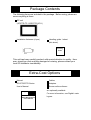
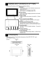
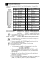
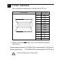
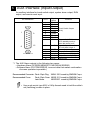
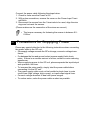
WARNING • When connecting power cable terminals to the GP unit, be sure the cable has been unplugged from the power outlet, to prevent an electric shock. • When replacing the backlight, be sure to turn the GP power OFF and wear gloves to avoid burns or electric shock. • High voltage runs through the GP unit, so if the unit is disassembled there is a danger of an electric shock. Do NOT take the unit apart. • Do not use power beyond the specified voltage range. If you do, it may cause a fire or an electric shock. • Do not modify the GP unit. It may cause a fire or an electric shock. • Do not use the GP in an environment with flammable gas in the surrounding atmosphere. It may cause explosion. • The GP uses a lithium battery for backing up its internal clock data. If the battery is incorrectly replaced, the battery may explode. To avoid the danger, do not replace the battery yourself. When the battery needs a replacement, please consult with your local GP distributor. • Do not use touch panel switches in life-related or important disaster prevention situations. For safety related switches, such as an emergency switch. use a separate mechanical switch. • Please design your system so that the machine will not malfunction by a communication fault between the GP and its host controller. If not, there could be a danger of personal injury or equipment damage. To Prevent Damage: • Do not hit the touch panel with a hard or heavy object, or press the touch panel with too much force, for it may cause irreparable damage. • Do not use GP in an environment where the surrounding temperature exceeds the specification range, for it may damage the unit. • Please ensure that liquids or metal do not enter the GP unit, for it may cause malfunction or a short. • Please avoid using the unit in areas where sudden, large changes in temperature may occur. These changes can cause condensation to form inside the unit, possibly causing an accident. • To prevent heat building up inside the GP, please do not install GP where its ventilation holes may be blocked, or where heat cannot escape. Also, please avoid using or storing the GP in an extremely hot place. • Do not operate the GP in areas with temperatures and humidity in express of those levels specified to prevent the GP’s touch panel from becoming warped or bent. • Please avoid using or storing the GP under direct sunlight or in a dusty environment. • The GP is a high accuracy electronic device, so please avoid using or storing it where it can receive strong impact or vibration. • Avoid either using or storing GP where vaporized chemicals or chemicals are present in the atmosphere. • Do NOT use paint thinner or organic solvents to clean the GP unit or display. • Be sure to back up all GP screen data regularly. • After turning this unit OFF, be sure to wait a few seconds before turning ON again. If the unit is started within a few seconds, it may not start up correctly. Package Contents The following items are included in the package. Before using, please ensure everything is there. GP unit (GP577R-TC11/GP577R-SC11) Installation fasteners (4 pcs) Handling guide 1 sheet (this sheet) Handling Guide This unit has been carefully packed, with special attention to quality. However, should you find anything damaged or missing, please contact your local GP distributor immediately. Extra-Cost Options Manual Cables GP477R/577R Series Adapters User’s Manual Screen editor software Digital are optionally available. For more information, see Digital's cata- GP477R/577R Series User's Manual logues. 1 Names and Functions of GP Parts Names and Functions of GP Parts are explained below. A:Display The monitor screen that indicates screens and data of the host. GP577R-TC11 TFT-type color LCD GP577R-SC11 STN-type color LCD B:Touch Panel Runs any screen change operations and sends data to the PLC. C:Power Lamp Lights up when the power is turned On. (Green LED) C A,B D:Power Input Terminal Block The input and ground terminals for AC power cable. E:Auxiliary Input/Output (AUX) Operates the Touch Switch, System Alarm, Buzzer, Run outputs, and Remote Reset inputs. F: Serial Interface RS-232C, RS-422 (Serial) interface. Connect to the Host. G:Printer Interface Connect the printer here. D E F G H H:Tool Connector Connect the Downloading Cable, or a Bar Code Reader here. 2 Dimensions The drawings below illustrate the dimensions of the GP577R-TC11 and GP577R-SC11 unit. Top View 301 Front View Side View 85 77.5 7.5 243 158.4 317 211.2 227 unit:mm 3 Serial Interface This is GP’s serial port for RS-232C and RS-422 interface. Connect GP’s host here. 1 14 Pin # Signal Name 1 FG 2 SD 3 RD 4 RS 5 CS 6 NC 7 GND 8 9 13 25 10 11 Condition Pin # Signal Name Frame ground 14 VCC 15 SDB 16 RDB 17 NC 18 CSB No connection 19 ERB Signal ground 20 ER 21 CSA 22 ERA 23 RESERVED 24 NC 25 RESERVED Send data (RS-232C) Receive data (RS-232C) Request send (RS-232C) Clear send (RS-232C) Carrier detect (RS-232C) Termination TRMX (RS-422) Receive data A RDA (RS-422) Send data A SDA (RS-422) CD 12 NC No connection 13 NC No connection Condition 5V±5% output 0.25A Send data B (RS-422) Receive data B (RS-422) No connection Clear send B (RS-422) Enable receive B (RS-422) Enable receive (RS-232C) Clear send A (RS-422) Enable receive A (RS-422) Reserved for future use No connection Reserved for future use RecommendedConnector: Dsub 25 pin plug XM2A-2501 <made by OMRON Corp.> RecommendedCover: Dsub 25 pin Cover XM2S-2511 <made by OMRON Corp.> Jack Screw XM2Z-0071 <made by OMRON Corp.> • Use rough metric type M2.6 x 0.45p threads used to hold the cable’s set (fastening) screws in place. RecommendedCable: CO-MA-VV-SB5P x 28AWG <madebyHITACHICableLtd.> • Since Pin#14(VCC)is unprotected, be sure to keep the output current in the rated range. • Be sure to connect this unit's SG/GND (Signal Ground) terminal to the other unit's Signal Ground terminal. When making a cable, please be aware of the following: <For RS-422 Connection> • The following pairs of pin #’s must be connected to each other ...#18 (CSB) <-> #19 (ERB) ...#21 (CSA) <-> #22 (ERA) • When connecting the RS-422 cable and the #9 (TRMX) and #10 (RDA) points, a termination resistance of 100Ω is added between RDA and RDB. • When the GP is set as a Memory Link type and the cable type is RS-422, a 4-line system must be setup. <For RS-232C connection> • Do not connect #9 (TRMX), #10 (RDA), #11 (SDA), #15 (SDB), #16 (RDB), #18 (CSB), #19 (ERB), #21 (CSA), and #22 (ERA). 4 Printer Interface This is the printer interface port in the rear side of GP unit. Pin Connection 1 7 14 8 Pin # Signal Name 1 PSTB 2 PDB0 3 PDB1 4 PDB2 5 PDB3 6 PDB4 7 PDB5 8 PDB6 9 PDB7 *1 10 INIT 11 BUSY 12 NC 13 NC 14 GND *1 When not using the INIT signal, the 10 pin connection becomes unnecessary. Recommended Connector:FCN-787P014-G/R <manufactured by FUJITSU, Inc.> Recommended Cover: FCN-780C014-D/E <manufactured by FUJITSU, Inc.> • Do not connect to pin #12 and #13. 5 AUX Interface (Input/Output) An auxiliary interface for touch switch output, system alarm output, RUN output, and remote reset input. Pin Connection 1 9 15 8 1 2 3 4 5 6 7 8 9 Signal Name TSW0 TSW1 TSW2 TSW3 TSW4 TSW5 TSW6 TSW7 RUN 10 ALARM 11 12 13 14 15 BUZZ DC24V AIN-C AOUT-C RESET Pin # Contents Touch Switch Output (8 bit) Output: On in RUN mode; Off in standby mode or when the power is off. Alarm Output: When On, GP unit alarm origin *1 Buzzer Output Output-Common (DC24V) Input-Common (DC24V) Output-Common (GND) Reset Input *1 The AUX Alarm outputs in the following two cases: • Hardware Alarm (SCREEN MEMORY CHECKSUM ERROR) • Software Alarm (SYSTEM ERROR, incorrect data that makes continuation of screen operation impossible.) Recommended Connector: Dsub 15 pin Plug XM2A-1501 <made by OMRON Corp.> Recommended Cover: Dsub 15 pin Cover XM2S-1511 <made by OMRON Corp.> Jack Screw XM2Z-0071 <made by OMRON Corp.> • Use rough metric type M2.6 x 0.45p threads used to hold the cable’s set (fastening) screws in place. 6 Installation Confirm the Installation Gasket’s Seating It is strongly recommended that you use the gasket. Place the GP on a level surface with the display panel facing downward. Check that the GP’s installation gasket is seated securely into the gasket’s groove, which runs around the perimeter of the panel’s frame. Installation Gasket Rear face Before installing the GP into a cabinet or panel, check that the Installation gasket is securely attached to the unit. Cut a hole, and mount the GP to the panel from the front. under 4-R2 Unit: mm 228 ± 0.5 302 ± 0.5 1.6mm to 10mm Panel thickness Attach the Installation Fasteners from behind. Fasten the screw of the installation fasteners with a screwdriver. Panel GP unit • Tightening the screws with too much force can cause a damage. • The fastening torque necessary for waterproofing is 0.5-0.6N•m. 7 Wiring WARNING • To avoid electric shock, be sure the Power Cable is unplugged from the power outlet when connecting the cable to the GP unit. • GP577R-TC11 and GP577R-SC11 can only take AC100V input. If you supply power other than AC100V, you will damage its power supply and the GP unit. • There is no power switch on the GP unit, so please use a breaker switch. • When the FG terminal is connected, be sure the wire is grounded. Not grounding the GP unit will result in excess noise and vibrations. • Wherever you can, use thick wires (max. 2 mm2) for power terminals, and provide an extra twist to the wire during connection. • Please use Ring Terminals with the size described below. • To avoid a short among the ring terminals when the screws get Over φ 3.2mm Under 6.0mm loosen, please use ring terminals with a sleeve. Rear side L N FG L N FG Ring Terminals*1 Power Input Terminal Block *1 AC100V L=AC Input Terminal ..................... live line AC100V N=AC Input Terminal ..................... neutral line FG=Ground Terminal connected to the GP chassis *1 Ring Terminal to use: V2-MS3 (made by JST) Connect the power cable following the steps below. 1. Check to make sure the Power is Off. 2. With a plus screwdriver, remove the cover on the Power Input Terminal Block. 3. Disconnect the screws from the 3 terminals to be used, align the wire rings and re-insert the screws. (Please make sure the connection of the wires are correct.) • The torque necessary for fastening the screws is between 0.50.6N•m. 8 Precautions for Supplying Power Please pay special attention to the following instructions when connecting the power cable to the GP unit. • If the supply voltage exceeds the GP unit range, connect a voltage transformer. • For between the line and ground, select a power supply that is low in noise. If there is an excess amount of noise, connect a noise reducing transformer. • When supplying power to the GP unit, please separate the input/output and operation unit lines. • To increase the noise quality, simply twist the power cable before connecting it to the GP unit. • The power supply cable must not be bundled or kept close to main circuit lines (high voltage, high current), or input/output signal lines. • Connect a surge absorber to deal with power surges. • To reduce noise, make the power cable as short as possible. 9 Precaution for Grounding • From the FG terminal at the rear side of GP unit, please take grounding exclusively [within ground resistance of 100 Ω]. 10 Precautions for Input/Output Signal Lines • Input and Output signal lines must be separated from the power control cables for operational circuits. • if this is not possible, use a shielded cable and the shield should be grounded. 11 Replacing the Backlight • The backlight on this unit can be replaced. For an explanation of how to replace it, please refer to the G-477R/ 577R Series User’s Manual (sold separately) or the instruction manual which comes with replacement backlights (sold separately). Applicable backlight models GP unit Backlight model GP577R-TC11 GP577RT-BL00-MS GP577R-SC11 GP577RS-BL00-MS • Using any backlight other than the applicable models shown above may cause an accident or breakdown.