1
AlphaServer 1000
Service Guide
Order Number: EK–DTLSV–SV. B01
Digital Equipment Corporation
Maynard, Massachusetts
First Printing, February 1995
Second Printing, July 1995
Digital Equipment Corporation makes no representations that the use of its products in the
manner described in this publication will not infringe on existing or future patent rights, nor do
the descriptions contained in this publication imply the granting of licenses to make, use, or sell
equipment or software in accordance with the description.
Possession, use, or copying of the software described in this publication is authorized only pursuant
to a valid written license from Digital or an authorized sublicensor.
Copyright © Digital Equipment Corporation, 1995. All Rights Reserved.
The following are trademarks of Digital Equipment Corporation: AXP, DEC, DECchip, DEC VET,
Digital, OpenVMS, StorageWorks, VAX DOCUMENT, the AXP logo, and the DIGITAL logo.
Digital UNIX is a registered trademark in the United States and other countries licensed
exclusively through X/Open Company Ltd. Windows NT is a trademark of Microsoft Corp.
All other trademarks and registered trademarks are the property of their respective holders.
FCC NOTICE: The equipment described in this manual generates, uses, and may emit radio
frequency energy. The equipment has been type tested and found to comply with the limits for
a Class B computing device pursuant to Subpart J of Part 15 of FCC Rules, which are designed
to provide reasonable protection against such radio frequency interference when operated in a
commercial environment. Operation of this equipment in a residential area may cause interference,
in which case the user at his own expense may be required to take measures to correct the
interference.
S2920
This document was prepared using VAX DOCUMENT Version 2.1.
Contents
Preface . . . . . . . . . . . . . . . . . . . . . . . . . . . . . . . . . . . . . . . . . . . . . . . .
xi
1 Troubleshooting Strategy
1.1
1.1.1
1.2
1.3
Troubleshooting the System
Problem Categories . . .
Service Tools and Utilities .
Information Services . . . . .
.
.
.
.
.
.
.
.
.
.
.
.
.
.
.
.
.
.
.
.
.
.
.
.
.
.
.
.
.
.
.
.
.
.
.
.
.
.
.
.
.
.
.
.
.
.
.
.
.
.
.
.
.
.
.
.
.
.
.
.
.
.
.
.
.
.
.
.
.
.
.
.
.
.
.
.
.
.
.
.
.
.
.
.
.
.
.
.
.
.
.
.
.
.
.
.
1–1
1–2
1–7
1–9
Interpreting Error Beep Codes . . . . . . . . . . . . .
SROM Memory Power-Up Tests . . . . . . . . .
Power-Up Screen . . . . . . . . . . . . . . . . . . . . . . .
Console Event Log . . . . . . . . . . . . . . . . . . .
Mass Storage Problems Indicated at Power-Up
Storage Device LEDs . . . . . . . . . . . . . . . . . . . .
EISA Bus Problems Indicated at Power-Up . . .
Additional EISA Troubleshooting Tips . . . .
PCI Bus Problems Indicated at Power-Up . . . .
Fail-Safe Loader . . . . . . . . . . . . . . . . . . . . . . . .
Fail-Safe Loader Functions . . . . . . . . . . . .
Activating the Fail-Safe Loader . . . . . . . . .
Power-Up Sequence . . . . . . . . . . . . . . . . . . . . .
AC Power-Up Sequence . . . . . . . . . . . . . . .
DC Power-Up Sequence . . . . . . . . . . . . . . .
Firmware Power-Up Diagnostics . . . . . . . . . . .
Serial ROM Diagnostics . . . . . . . . . . . . . . .
Console Firmware-Based Diagnostics . . . . .
.
.
.
.
.
.
.
.
.
.
.
.
.
.
.
.
.
.
.
.
.
.
.
.
.
.
.
.
.
.
.
.
.
.
.
.
.
.
.
.
.
.
.
.
.
.
.
.
.
.
.
.
.
.
.
.
.
.
.
.
.
.
.
.
.
.
.
.
.
.
.
.
.
.
.
.
.
.
.
.
.
.
.
.
.
.
.
.
.
.
.
.
.
.
.
.
.
.
.
.
.
.
.
.
.
.
.
.
.
.
.
.
.
.
.
.
.
.
.
.
.
.
.
.
.
.
.
.
.
.
.
.
.
.
.
.
.
.
.
.
.
.
.
.
.
.
.
.
.
.
.
.
.
.
.
.
.
.
.
.
.
.
2–2
2–3
2–7
2–8
2–9
2–11
2–14
2–15
2–16
2–17
2–17
2–17
2–19
2–19
2–20
2–20
2–20
2–21
2 Power-Up Diagnostics and Display
2.1
2.1.1
2.2
2.2.1
2.3
2.4
2.5
2.5.1
2.6
2.7
2.7.1
2.7.2
2.8
2.8.1
2.8.2
2.9
2.9.1
2.9.2
iii
3 Running System Diagnostics
3.1
3.2
3.3
3.3.1
3.3.2
3.3.3
3.3.4
3.3.5
3.3.6
3.3.7
3.3.8
3.3.9
3.4
3.5
Running ROM-Based Diagnostics . . .
Command Summary . . . . . . . . . . . . .
Command Reference . . . . . . . . . . . . .
test . . . . . . . . . . . . . . . . . . . . . . . .
cat el and more el . . . . . . . . . . . .
memory . . . . . . . . . . . . . . . . . . . .
netew . . . . . . . . . . . . . . . . . . . . . .
network . . . . . . . . . . . . . . . . . . . .
net -s . . . . . . . . . . . . . . . . . . . . . .
net -ic . . . . . . . . . . . . . . . . . . . . . .
kill and kill_diags . . . . . . . . . . . .
show_status . . . . . . . . . . . . . . . . .
Acceptance Testing and Initialization .
DEC VET . . . . . . . . . . . . . . . . . . . . . .
.
.
.
.
.
.
.
.
.
.
.
.
.
.
.
.
.
.
.
.
.
.
.
.
.
.
.
.
.
.
.
.
.
.
.
.
.
.
.
.
.
.
.
.
.
.
.
.
.
.
.
.
.
.
.
.
.
.
.
.
.
.
.
.
.
.
.
.
.
.
.
.
.
.
.
.
.
.
.
.
.
.
.
.
.
.
.
.
.
.
.
.
.
.
.
.
.
.
.
.
.
.
.
.
.
.
.
.
.
.
.
.
.
.
.
.
.
.
.
.
.
.
.
.
.
.
.
.
.
.
.
.
.
.
.
.
.
.
.
.
.
.
.
.
.
.
.
.
.
.
.
.
.
.
.
.
.
.
.
.
.
.
.
.
.
.
.
.
.
.
.
.
.
.
.
.
.
.
.
.
.
.
.
.
.
.
.
.
.
.
.
.
.
.
.
.
.
.
.
.
.
.
.
.
.
.
.
.
.
.
.
.
.
.
.
.
.
.
.
.
.
.
.
.
3–1
3–2
3–3
3–4
3–7
3–8
3–10
3–12
3–14
3–15
3–16
3–17
3–18
3–18
Fault Detection and Reporting . . . . . . . . . . . . .
Machine Check/Interrupts . . . . . . . . . . . . .
Error Logging and Event Log Entry Format . .
Event Record Translation . . . . . . . . . . . . . . . . .
OpenVMS Translation Using DECevent . .
Digital UNIX Translation Using DECevent
.
.
.
.
.
.
.
.
.
.
.
.
.
.
.
.
.
.
.
.
.
.
.
.
.
.
.
.
.
.
.
.
.
.
.
.
.
.
.
.
.
.
.
.
.
.
.
.
.
.
.
.
.
.
4–1
4–2
4–4
4–5
4–5
4–6
Verifying System Configuration . . . . . . . . . . . . . . . . . . . . .
System Firmware . . . . . . . . . . . . . . . . . . . . . . . . . . . . .
Switching Between Interfaces . . . . . . . . . . . . . . . . . . .
Verifying Configuration: ARC Menu Options for
Windows NT . . . . . . . . . . . . . . . . . . . . . . . . . . . . . . . .
Display Hardware Configuration . . . . . . . . . . . . . .
Set Default Variables . . . . . . . . . . . . . . . . . . . . . . .
Verifying Configuration: SRM Console Commands for
DEC OSF/1 and OpenVMS . . . . . . . . . . . . . . . . . . . . .
show config . . . . . . . . . . . . . . . . . . . . . . . . . . . . . . .
show device . . . . . . . . . . . . . . . . . . . . . . . . . . . . . .
show memory . . . . . . . . . . . . . . . . . . . . . . . . . . . . .
Setting and Showing Environment Variables . . . . .
System Bus Options . . . . . . . . . . . . . . . . . . . . . . . . . . . . . .
CPU Daughter Board . . . . . . . . . . . . . . . . . . . . . . . . . .
5–2
5–2
5–4
4 Error Log Analysis
4.1
4.1.1
4.2
4.3
4.3.1
4.3.2
5 System Configuration and Setup
5.1
5.1.1
5.1.2
5.1.3
5.1.3.1
5.1.3.2
5.1.4
5.1.4.1
5.1.4.2
5.1.4.3
5.1.4.4
5.2
5.2.1
iv
5–4
5–5
5–7
5–9
5–9
5–11
5–12
5–12
5–17
5–19
5.2.2
5.3
5.4
5.5
5.5.1
5.6
5.6.1
5.6.2
5.6.3
5.6.4
5.7
5.8
5.8.1
5.8.2
5.9
5.10
Memory Modules . . . . . . . . . . . . . . . . . . . . . . . . . . . . .
Motherboard . . . . . . . . . . . . . . . . . . . . . . . . . . . . . . . . . . .
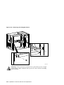
EISA Bus Options . . . . . . . . . . . . . . . . . . . . . . . . . . . . . . .
ISA Bus Options . . . . . . . . . . . . . . . . . . . . . . . . . . . . . . . .
Identifying ISA and EISA options . . . . . . . . . . . . . . . .
EISA Configuration Utility . . . . . . . . . . . . . . . . . . . . . . . .
Before You Run the ECU . . . . . . . . . . . . . . . . . . . . . . .
How to Start the ECU . . . . . . . . . . . . . . . . . . . . . . . . .
Configuring EISA Options . . . . . . . . . . . . . . . . . . . . . .
Configuring ISA Options . . . . . . . . . . . . . . . . . . . . . . .
PCI Bus Options . . . . . . . . . . . . . . . . . . . . . . . . . . . . . . . .
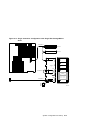
SCSI Buses . . . . . . . . . . . . . . . . . . . . . . . . . . . . . . . . . . . .
Single Controller (On-Board) Configurations . . . . . . . .
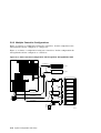
Multiple Controller Configurations . . . . . . . . . . . . . . .
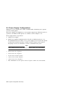
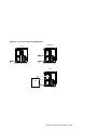
Power Supply Configurations . . . . . . . . . . . . . . . . . . . . . . .
Console Port Configurations . . . . . . . . . . . . . . . . . . . . . . . .
5–19
5–20
5–21
5–21
5–22
5–22
5–23
5–24
5–25
5–26
5–28
5–28
5–29
5–32
5–34
5–37
6 AlphaServer 1000 FRU Removal and Replacement
6.1
6.2
6.2.1
6.2.2
6.2.3
6.2.4
6.2.5
6.2.6
6.2.7
6.2.8
6.2.9
6.2.10
6.2.11
6.2.12
6.2.13
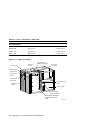
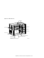
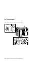
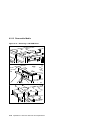
AlphaServer 1000 FRUs . . . . . . . . . . . . . . . . . . . . . . . .
Removal and Replacement . . . . . . . . . . . . . . . . . . . . . .
Cables . . . . . . . . . . . . . . . . . . . . . . . . . . . . . . . . . .
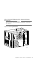
CPU Daughter Board . . . . . . . . . . . . . . . . . . . . . . .
Fans . . . . . . . . . . . . . . . . . . . . . . . . . . . . . . . . . . . .
StorageWorks Drive . . . . . . . . . . . . . . . . . . . . . . . .
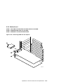
Internal StorageWorks Backplane . . . . . . . . . . . . .
Memory Modules . . . . . . . . . . . . . . . . . . . . . . . . . .
Interlock Switch . . . . . . . . . . . . . . . . . . . . . . . . . . .
Motherboard . . . . . . . . . . . . . . . . . . . . . . . . . . . . .
NVRAM Chip (E14) and NVRAM TOY Clock Chip
(E78) . . . . . . . . . . . . . . . . . . . . . . . . . . . . . . . . . . .
OCP Module . . . . . . . . . . . . . . . . . . . . . . . . . . . . . .
Power Supply . . . . . . . . . . . . . . . . . . . . . . . . . . . . .
Speaker . . . . . . . . . . . . . . . . . . . . . . . . . . . . . . . . .
Removable Media . . . . . . . . . . . . . . . . . . . . . . . . . .
.
.
.
.
.
.
.
.
.
.
.
.
.
.
.
.
.
.
.
.
.
.
.
.
.
.
.
.
.
.
6–1
6–6
6–8
6–22
6–23
6–25
6–26
6–28
6–32
6–33
.
.
.
.
.
.
.
.
.
.
.
.
.
.
.
6–37
6–37
6–40
6–41
6–42
v
A Default Jumper Settings
A.1
A.2
A.3
Motherboard Jumpers . . . . . . . . . . . . . . . . . . . . . . . . . . . .
CPU Daughter Board (J3 and J4) Supported Settings . . . .
CPU Daughter Board (J1 Jumper) . . . . . . . . . . . . . . . . . . .
A–2
A–4
A–6
Sample Hardware Configuration Display . . . . . . . . . . .
5–6
Glossary
Index
Examples
5–1
Figures
2–1
2–2
2–3
2–4
2–5
2–6
5–1
5–2
5–3
5–4
5–5
5–6
5–7
5–8
5–9
5–10
5–11
5–12
vi
Jumper J1 on the CPU Daughter Board . . . . . .
AlphaServer 1000 Memory Layout . . . . . . . . . . .
StorageWorks Disk Drive LEDs (SCSI) . . . . . . .
Floppy Drive Activity LED . . . . . . . . . . . . . . . . .
CD–ROM Drive Activity LED . . . . . . . . . . . . . .
Jumper J1 on the CPU Daughter Board . . . . . .
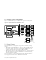
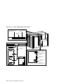
System Architecture: AlphaServer 1000 . . . . . .
Device Name Convention . . . . . . . . . . . . . . . . . .
Card Cages and Bus Locations . . . . . . . . . . . . . .
Memory Layout on the Motherboard . . . . . . . . .
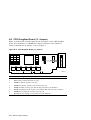
ISA and ISA Boards . . . . . . . . . . . . . . . . . . . . . .
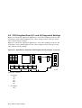
PCI Board . . . . . . . . . . . . . . . . . . . . . . . . . . . . .
Single Controller Configuration with Dual Bus
StorageWorks Shelf . . . . . . . . . . . . . . . . . . . . . .
Single Controller Configuration with Single Bus
StorageWorks Shelf . . . . . . . . . . . . . . . . . . . . . .
Dual Controller Configuration with Single Bus
StorageWorks Shelf . . . . . . . . . . . . . . . . . . . . . .
Dual Controller Configuration with Dual Bus
StorageWorks Shelf . . . . . . . . . . . . . . . . . . . . . .
Power Supply Configurations . . . . . . . . . . . . . . .
Power Supply Cable Connections . . . . . . . . . . . .
.
.
.
.
.
.
.
.
.
.
.
.
.
.
.
.
.
.
.
.
.
.
.
.
.
.
.
.
.
.
.
.
.
.
.
.
.
.
.
.
.
.
.
.
.
.
.
.
.
.
.
.
.
.
.
.
.
.
.
.
2–6
2–7
2–12
2–12
2–13
2–18
5–2
5–11
5–18
5–20
5–22
5–28
.....
5–30
.....
5–31
.....
5–32
.....
.....
.....
5–33
5–35
5–36
6–1
6–2
6–3
6–4
6–5
6–6
6–7
6–8
6–9
6–10
6–11
6–12
6–13
6–14
6–15
6–16
6–17
6–18
6–19
6–20
6–21
6–22
6–23
6–24
6–25
6–26
6–27
6–28
6–29
6–30
6–31
6–32
6–33
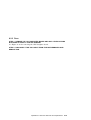
FRUs, Front Right . . . . . . . . . . . . . . . . . . . . . . . . . . . .
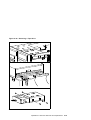
FRUs, Rear Left . . . . . . . . . . . . . . . . . . . . . . . . . . . . . .
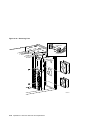
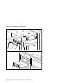
Opening Front Door . . . . . . . . . . . . . . . . . . . . . . . . . . .
Removing Top Cover and Side Panels . . . . . . . . . . . . .
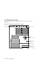
Floppy Drive Cable (34-Pin) . . . . . . . . . . . . . . . . . . . . .
OCP Module Cable (10-Pin) . . . . . . . . . . . . . . . . . . . . .
Power Cord . . . . . . . . . . . . . . . . . . . . . . . . . . . . . . . . .
Power Supply Current Sharing Cable (3-Pin) . . . . . . .
Power Supply DC Cable Assembly . . . . . . . . . . . . . . . .
Power Supply Storage Harness (12-Pin) . . . . . . . . . . . .
Interlock/Server Management Cable (2-pin) . . . . . . . . .
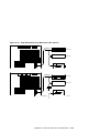
Internal StorageWorks Jumper Cable (50-Pin) . . . . . . .
SCSI (J15 StorageWorks Shelf to Bulkhead Connector
or Bulkhead to Multinode) Cable (50-Pin) . . . . . . . . . .
SCSI (J15 StorageWorks Shelf to Bulkhead Connector
or Bulkhead to Multinode) Cable (50-Pin) . . . . . . . . . .
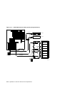
SCSI (J1 or J14 StorageWorks Shelf to Bulkhead
Connector) Cable (50-Pin) . . . . . . . . . . . . . . . . . . . . . .
SCSI (Embedded 8-bit) Multinode Cable (50-Pin) . . . .
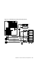
SCSI RAID Internal Cable (50-Pin)
(Single-Channel) . . . . . . . . . . . . . . . . . . . . . . . . . . . . .
SCSI RAID Internal Cable (50-Pin) (Dual-Channel) . .
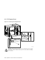
Removing CPU Daughter Board . . . . . . . . . . . . . . . . .
Removing Fans . . . . . . . . . . . . . . . . . . . . . . . . . . . . . .
Removing StorageWorks Drive . . . . . . . . . . . . . . . . . . .
Removing Power Supply . . . . . . . . . . . . . . . . . . . . . . .
Removing Internal StorageWorks Backplane . . . . . . . .
Memory Layout on Motherboard . . . . . . . . . . . . . . . . .
Removing SIMMs from Motherboard . . . . . . . . . . . . . .
Installing SIMMs on Motherboard . . . . . . . . . . . . . . . .
Removing the Interlock Safety Switch . . . . . . . . . . . . .
Removing EISA and PCI Options . . . . . . . . . . . . . . . . .
Removing CPU Daughter Board . . . . . . . . . . . . . . . . .
Removing Motherboard . . . . . . . . . . . . . . . . . . . . . . . .
Motherboard Layout . . . . . . . . . . . . . . . . . . . . . . . . . .
Removing Front Door . . . . . . . . . . . . . . . . . . . . . . . . . .
Removing Front Panel . . . . . . . . . . . . . . . . . . . . . . . . .
6–4
6–5
6–6
6–7
6–8
6–9
6–10
6–11
6–12
6–13
6–14
6–15
6–16
6–17
6–18
6–19
6–20
6–21
6–22
6–24
6–25
6–26
6–27
6–28
6–29
6–30
6–32
6–33
6–34
6–35
6–36
6–37
6–38
vii
6–34
6–35
6–36
6–37
6–38
6–39
A–1
A–2
A–3
A–4
Removing the OCP Module . . . . . . . . . . . . . . .
Removing Power Supply . . . . . . . . . . . . . . . . .
Removing Speaker . . . . . . . . . . . . . . . . . . . . . .
Removing a CD–ROM Drive . . . . . . . . . . . . . .
Removing a Tape Drive . . . . . . . . . . . . . . . . . .
Removing a Floppy Drive . . . . . . . . . . . . . . . . .
Motherboard Jumpers (Default Settings) . . . . .
AlphaServer 1000 4/200 CPU Daughter Board
(Jumpers J3 and J4) . . . . . . . . . . . . . . . . . . . .
AlphaServer 1000 4/233 CPU Daughter Board
(Jumpers J3 and J4) . . . . . . . . . . . . . . . . . . . .
CPU Daughter Board (J1 Jumper) . . . . . . . . . .
.
.
.
.
.
.
.
.
.
.
.
.
.
.
.
.
.
.
.
.
.
.
.
.
.
.
.
.
.
.
.
.
.
.
.
.
.
.
.
.
.
.
6–39
6–40
6–41
6–42
6–43
6–44
A–2
......
A–4
......
......
A–5
A–6
Diagnostic Flow for Power Problems . . . . . . . . . . . . . .
Diagnostic Flow for Problems Getting to Console
Mode . . . . . . . . . . . . . . . . . . . . . . . . . . . . . . . . . . . . . .
Diagnostic Flow for Problems Reported by the Console
Program . . . . . . . . . . . . . . . . . . . . . . . . . . . . . . . . . . . .
Diagnostic Flow for Boot Problems . . . . . . . . . . . . . . .
Diagnostic Flow for Errors Reported by the Operating
System . . . . . . . . . . . . . . . . . . . . . . . . . . . . . . . . . . . . .
Interpreting Error Beep Codes . . . . . . . . . . . . . . . . . . .
SROM Memory Tests, CPU Jumper J1 . . . . . . . . . . . .
Mass Storage Problems . . . . . . . . . . . . . . . . . . . . . . . .
Troubleshooting Problems with SWXCR-xx RAID
Controller . . . . . . . . . . . . . . . . . . . . . . . . . . . . . . . . . . .
EISA Troubleshooting . . . . . . . . . . . . . . . . . . . . . . . . .
PCI Troubleshooting . . . . . . . . . . . . . . . . . . . . . . . . . . .
Summary of Diagnostic and Related Commands . . . . .
AlphaServer 1000 Fault Detection and Correction . . . .
Listing the ARC Firmware Device Names . . . . . . . . . .
ARC Firmware Device Names . . . . . . . . . . . . . . . . . . .
ARC Firmware Environment Variables . . . . . . . . . . . .
Environment Variables Set During System
Configuration . . . . . . . . . . . . . . . . . . . . . . . . . . . . . . . .
Operating System Memory Requirements . . . . . . . . . .
1–3
Tables
1–1
1–2
1–3
1–4
1–5
2–1
2–2
2–3
2–4
2–5
2–6
3–1
4–1
5–1
5–2
5–3
5–4
5–5
viii
1–4
1–5
1–6
1–7
2–2
2–4
2–9
2–11
2–14
2–16
3–2
4–2
5–5
5–5
5–8
5–13
5–20
5–6
5–7
6–1
6–2
Summary of Procedure for Configuring EISA Bus
(EISA Options Only) . . . . . . . . . . . . . . . . . . . . . . . . . .
Summary of Procedure for Configuring EISA Bus with
ISA Options . . . . . . . . . . . . . . . . . . . . . . . . . . . . . . . .
AlphaServer 1000 FRUs . . . . . . . . . . . . . . . . . . . . . . . .
Power Cord Order Numbers . . . . . . . . . . . . . . . . . . . . .
5–26
5–27
6–2
6–10
ix
Preface
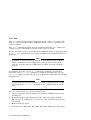
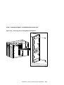
This guide describes the procedures and tests used to service AlphaServer 1000
systems. AlphaServer 1000 systems use a deskside ‘‘wide-tower’’ enclosure.
Intended Audience
This guide is intended for use by Digital Equipment Corporation service personnel
and qualified self-maintenance customers.
Conventions
The following conventions are used in this guide:
xi
Convention
Meaning
Return
A key name enclosed in a box indicates that you press that key.
Ctrl/x
Ctrl/x indicates that you hold down the Ctrl key while you
press another key, indicated here by x. In examples, this key
combination is enclosed in a box, for example, Ctrl/C .
Warning
Warnings contain information to prevent personal injury.
Caution
Cautions provide information to prevent damage to equipment
or software.
Note
A note calls the reader’s attention to any information that may
be of special importance.
boot
Console and operating system commands are shown in
monospace type.
[]
In command format descriptions, brackets indicate optional
elements.
show config
Console command abbreviations must be entered exactly as
shown. Commands shown in lowercase can be entered in
either uppercase or lowercase.
italic type
In console command sections, italic type indicates a variable.
<>
In console mode online help, angle brackets enclose a
placeholder for which you must specify a value.
{}
In command descriptions, braces containing items separated by
commas imply mutually exclusive items.
Circled numbers provide a link between examples and text.
Related Documentation
•
AlphaServer 1000 Owner’s Guide, EK-DTLSV-OG
•
DEC Verifier and Exerciser Tool User’s Guide, AA-PTTMA-TE
•
Guide to Kernel Debugging, AA-PS2TA-TE
•
OpenVMS AXP Alpha System Dump Analyzer Utility Manual, AA-PV6UB-TE
•
DECevent Translation and Reporting Utility for OpenVMS User and Reference
Guide
•
DECevent Translation and Reporting Utility for Digital UNIX User and
Reference Guide
•
StorageWorks RAID Array 200 Subsystem Family Software User’s Guide for
OpenVMS Alpha, AA-Q6WVA-TE
xii
1
Troubleshooting Strategy
This chapter describes the troubleshooting strategy for AlphaServer 1000
systems.
•
Section 1.1 provides questions to consider before you begin troubleshooting an
AlphaServer 1000 system.
•
Tables 1–1 through 1–5 provide a diagnostic flow for each category of system
problem.
•
Section 1.2 lists the product tools and utilities.
•
Section 1.3 lists available information services.
1.1 Troubleshooting the System
Before troubleshooting any system problem, check the site maintenance log for
the system’s service history. Be sure to ask the system manager the following
questions:
•
Has the system been used before and did it work correctly?
•
Have changes to hardware or updates to firmware or software been made to
the system recently?
•
What is the state of the system—is the operating system running?
If the operating system is down and you are not able to bring it up, use
the console environment diagnostic tools, such as the power-up display and
ROM-based diagnostics (RBDs).
If the operating system is running, use the operating system environment
diagnostic tools, such as error logs, crash dumps, and exercisers (DEC VET).
Troubleshooting Strategy 1–1
1.1.1 Problem Categories
System problems can be classified into the following five categories. Using these
categories, you can quickly determine a starting point for diagnosis and eliminate
the unlikely sources of the problem.
1. Power problems (Table 1–1)
2. No access to console mode (Table 1–2)
3. Console-reported failures (Table 1–3)
4. Boot failures (Table 1–4)
5. Operating system-reported failures (Table 1–5)
1–2 Troubleshooting Strategy
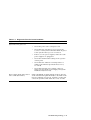
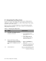
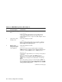
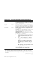
Table 1–1 Diagnostic Flow for Power Problems
Symptom
Action
System does not power on.
Power supply shuts down after a
few seconds (fan failure).
•
Check the power source and power cord.
•
Check that the system’s top cover is properly
secured. A safety interlock switch shuts off power
to the system if the top cover is removed.
•
If there are two power supplies, make sure both
power supplies are plugged in.
•
Check the On/Off switch setting on the operator
control panel.
•
Check that the ambient room temperature is
within environmental specifications (10–40°C,
50–104°F).
•
Check that internal power supply cables are
plugged in at both the power supply and system
motherboard (Section 5.9).
Using a flashlight, look through the front (to the left
of the internal StorageWorks shelf) to determine if the
fans are spinning at power-up. A failure of either fan
causes the system to shut down after a few seconds.
Troubleshooting Strategy 1–3
Table 1–2 Diagnostic Flow for Problems Getting to Console Mode
Symptom
Action
Power-up screen is not displayed.
Interpret the error beep codes at power-up (Section 2.1)
for a failure detected during self-tests.
Check that the keyboard and monitor are properly
connected and turned on.
If the power-up screen is not displayed, yet the system
enters console mode when you press Return , check that
the console environment variable is set correctly. If
you are using a VGA console terminal, the console
variable should be set to ‘‘graphics.’’ If you are using a
serial console terminal, the console variable should be
set to ‘‘serial.’’
If a VGA controller other than the standard on-board
VGA controller is being used, refer to Section 5.10 for
more information.
If console is set to serial, the power-up screen is
routed to the COM1 serial communication port
(Section 5.10) and cannot be viewed from the VGA
monitor.
Try connecting a console terminal to the COM1 serial
communication port (Section 5.10). If necessary use
an MMJ-to-9-pin adapter (H8571-J). Check the baud
rate setting for the console terminal and the system.
The system baud rate setting is 9600. When using the
COM1 port, you must set the console environment
variable to ‘‘serial.’’
For certain situations, power up using the fail-safe
loader (Section 2.7) to load new console firmware from
a diskette.
1–4 Troubleshooting Strategy
Table 1–3 Diagnostic Flow for Problems Reported by the Console Program
Symptom
Action
Power-up tests do not complete.
Interpret the error beep codes at power-up (Section 2.1)
and check the power-up screen (Section 2.2) for a
failure detected during self-tests.
If the power-up display stops on e6, an EISA or PCI
board is causing the system to hang.
Console program reports error:
•
Error beep codes report an
error at power-up.
•
Power-up screen includes
error messages.
Use the error beep codes (Section 2.1) and/or console
terminal (Section 2.2) to determine the error.
Examine the console event log (enter the cat el
command) (Section 2.2.1) or the power-up screen
(Section 2.2) to check for embedded error messages
recorded during power-up.
If the power-up screen or console event log indicates
problems with mass storage devices, or if storage
devices are missing from the show config display, use
the troubleshooting tables (Section 2.3) to determine
the problem.
If the power-up screen or console event log indicates
problems with EISA devices, or if EISA devices are
missing from the show config display, use the
troubleshooting table (Section 2.5) to determine the
problem.
If the power-up screen or console event log indicates
problems with PCI devices, or if PCI devices are
missing from the show config display, use the
troubleshooting table (Section 2.6) to determine the
problem.
Run the ROM-based diagnostic (RBD) tests
(Section 3.1) to verify the problem.
Troubleshooting Strategy 1–5
Table 1–4 Diagnostic Flow for Boot Problems
Symptom
Action
System cannot find boot device.
Check the system configuration for the correct device
parameters (node ID, device name, and so on).
•
For DEC OSF/1 and OpenVMS, use the
show config and show device commands
(Section 5.1).
•
For Windows NT, use the Display Hardware
Configuration display and the Set Default
Environment Variables display (Section 5.1).
Check the system configuration for the correct
environment variable settings.
•
For DEC OSF/1 and OpenVMS, examine the
auto_action, bootdef_dev, boot_osflags, and os_type
environment variables (Section 5.1.4.4).
For problems booting over a network, check the
ew*0_protocols or er*0_protocols environment
variable settings: Systems booting from a DEC
OSF/1 server should be set to bootp; systems
booting from an OpenVMS server should be set to
mop (Section 5.1.4.4).
•
Device does not boot.
For Windows NT, examine the FWSEARCHPATH,
AUTOLOAD, and COUNTDOWN environment
variables (Section 5.1.4.4).
For problems booting over a network, check the ew*0_
protocols or er*0_protocols environment variable
settings: Systems booting from a DEC OSF/1
server should be set to bootp; systems booting
from an OpenVMS server should be set to mop
(Section 5.1.4.4).
Run the device tests (Section 3.1) to check that the
boot device is operating.
1–6 Troubleshooting Strategy
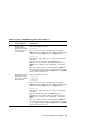
Table 1–5 Diagnostic Flow for Errors Reported by the Operating System
Symptom
System is hung or has crashed.
Action
Examine the crash dump file.
Refer to OpenVMS AXP Alpha System Dump Analyzer
Utility Manual for information on how to interpret
OpenVMS crash dump files.
Refer to the Guide to Kernel Debugging (AA–PS2TA–
TE) for information on using the DEC OSF/1 Krash
Utility.
Errors have been logged and the
operating system is up.
Examine the operating system error log files to isolate
the problem.
If the problem occurs intermittently, run an operating
system exerciser, such as DEC VET, to stress the
system.
Refer to the DEC Verifier and Exerciser Tool User’s
Guide (AA–PTTMA–TE) for instructions on running
DEC VET.
1.2 Service Tools and Utilities
This section lists the array of service tools and utilities available for acceptance
testing, diagnosis, and serviceability and provides recommendations for their use.
Error Handling/Logging
DEC OSF/1, OpenVMS, and Microsoft Windows NT operating systems provide
recovery from errors, fault handling, and event logging. The DECevent
Translation and Reporting Utility for OpenVMS and Error Report Formatter
(ERF) provides bit-to-text translation of event logs for interpretation. DEC
OSF/1 uses uerf to present the same kinds of information.
RECOMMENDED USE: Analysis of error logs is the primary method of
diagnosis and fault isolation. If the system is up, or you are able to bring it
up, look at this information first.
ROM-Based Diagnostics (RBDs)
Many ROM-based diagnostics and exercisers are embedded in AlphaServer
1000 systems. ROM-based diagnostics execute automatically at power-up and
can be invoked in console mode using console commands.
Troubleshooting Strategy 1–7
RECOMMENDED USE: ROM-based diagnostics are the primary means
of testing the console environment and diagnosing the CPU, memory,
Ethernet, I/O buses, and SCSI subsystems. Use ROM-based diagnostics
in the acceptance test procedures when you install a system, add a memory
module, or replace the following: CPU module, memory module, motherboard,
I/O bus device, or storage device. Refer to Chapter 3 for information on
running ROM-based diagnostics.
Loopback Tests
Internal and external loopback tests are used to isolate a failure by testing
segments of a particular control or data path. The loopback tests are a subset
of the ROM-based diagnostics.
RECOMMENDED USE: Use loopback tests to isolate problems with the
COM2 serial port, the parallel port, and Ethernet controllers. Refer to
Chapter 3 for instructions on performing loopback tests.
Firmware Console Commands
Console commands are used to set and examine environment variables
and device parameters, as well as to invoke ROM-based diagnostics and
exercisers. For example, the show memory, show configuration, and show
device commands are used to examine the configuration; the set (bootdef_
dev, auto_action, and boot_osflags) commands are used to set environment
variables; and the cdp command is used to configure DSSI parameters.
RECOMMENDED USE: Use console commands to set and examine
environment variables and device parameters and to run RBDs. Refer to
Section 5.1 for information on configuration-related firmware commands and
Chapter 3 for information on running RBDs.
Operating System Exercisers (DEC VET)
The Digital Verifier and Exerciser Tool (DEC VET) is supported by the DEC
OSF/1, OpenVMS, and Windows NT operating systems. DEC VET performs
exerciser-oriented maintenance testing of both hardware and operating
system.
RECOMMENDED USE: Use DEC VET as part of acceptance testing to
ensure that the CPU, memory, disk, tape, file system, and network are
interacting properly. Also use DEC VET to stress test the user’s environment
and configuration by simulating system operation under heavy loads to
diagnose intermittent system failures.
1–8 Troubleshooting Strategy
Crash Dumps
For fatal errors, such as fatal bugchecks, DEC OSF/1 and OpenVMS operating
systems will save the contents of memory to a crash dump file.
RECOMMENDED USE: Crash dump files can be used to determine why the
system crashed. To save a crash dump file for analysis, you need to know
the proper system settings. Refer to the OpenVMS AXP Alpha System Dump
Analyzer Utility Manual (AA-PV6UB-TE) or the Guide to Kernel Debugging
(AA–PS2TA–TE) for DEC OSF/1.
1.3 Information Services
Several information resources are available, including online information
for servicers and customers, computer-based training, and maintenance
documentation database services. A brief description of some of these resources
follows.
Training
The following Computer Based Training (CBT) and lecture lab courses are
available from the Digital training center:
•
Alpha Concepts
•
ISA and EISA Bus Concepts: EY-I113E-P0
•
RAID Concepts: EY-N935E
•
SCSI Concepts and Troubleshooting: EY-P841E, EY-N838E
Digital Assisted Services
Digital Assisted Services (DAS) offers products, services, and programs to
customers who participate in the maintenance of Digital computer equipment.
Components of Digital assisted services include:
•
Spare parts and kits
•
Diagnostics and service information/documentation
•
Tools and test equipment
•
Parts repair services, including Field Change Orders
Troubleshooting Strategy 1–9
2
Power-Up Diagnostics and Display
This chapter provides information on how to interpret error beep codes and
the power-up display on the console screen. In addition, a description of the
power-up and firmware power-up diagnostics is provided as a resource to aid in
troubleshooting.
•
Section 2.1 describes how to interpret error beep codes at power-up.
•
Section 2.1.1 describes SROM memory tests that can be run at power-up to
isolate failing SIMM memory.
•
Section 2.2 describes how to interpret the power-up screen display.
•
Section 2.3 describes how to troubleshoot mass-storage problems indicated at
power-up or storage devices missing from the show config display.
•
Section 2.4 shows the location of storage device LEDs.
•
Section 2.5 describes how to troubleshoot EISA bus problems indicated at
power-up or EISA devices missing from the show config display.
•
Section 2.6 describes how to troubleshoot PCI bus problems indicated at
power-up or PCI devices missing from the show config display.
•
Section 2.7 describes the use of the fail-safe loader.
•
Section 2.8 describes the power-up sequence.
•
Section 2.9 describes power-on self-tests.
Power-Up Diagnostics and Display 2–1
2.1 Interpreting Error Beep Codes
If errors are detected at power-up, audible beep codes are emitted from the
system. For example, if the SROM code could not find any good memory, you
would hear a 1-3-3 beep code (one beep, a pause, a burst of three beeps, a pause,
and another burst of three beeps).
The beep codes are the primary diagnostic tool for troubleshooting problems
when console mode cannot be accessed. Refer to Table 2–1 for information on
interpreting error beep codes.
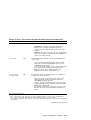
Table 2–1 Interpreting Error Beep Codes
Beep
Code
1-1-4
Problem
Corrective Action
The SROM code is unable to load the
console code: Flash ROM header area or
checksum error detected.
1. Use the Fail-Safe Loader to
load new ARC/SRM console code
(Section 2.7).
2. If successfully loading new
console firmware does not
solve the problem, replace the
motherboard (Chapter 6).
3-3-1
Generic system failure. Possible
problem sources include the following
motherboard components: native SCSI
controller (NCR 53C810), remote I/O chip
(Intel 87312), or NVRAM chip (position
E14).
1. Replace the NVRAM chip
(E14) on system motherboard
(Chapter 6.)
2. If replacing the NVRAM chip did
not solve the problem, replace
the motherboard (Chapter 6).
1-2-1
TOY NVRAM failure.
Replace the TOY NVRAM chip (E78)
on system motherboard (Chapter 6).
(continued on next page)
2–2 Power-Up Diagnostics and Display
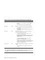
Table 2–1 (Cont.) Interpreting Error Beep Codes
Beep
Code
Problem
1-3-3
No usable memory detected.
Corrective Action
1. Verify that the memory modules
are properly seated and try
powering up again.
2. Swap bank 0 memory with
known good memory and run
SROM memory tests at powerup (Section 2.1.1).
3. If populating bank 0 with known
good memory does not solve
the problem, replace the CPU
daughter board (Chapter 6).
4. If replacing the CPU daughter
board does not solve the problem, replace the motherboard
(Chapter 6).
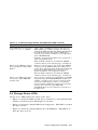
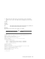
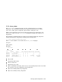
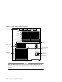
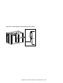
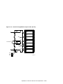
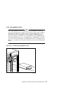
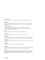
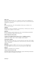
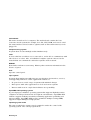
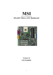
2.1.1 SROM Memory Power-Up Tests
To test SIMM memory and report the position of a failing SIMM, set SROM
power-up tests by using jumper J1 (Figure 2–1) on the CPU daughter board.
The progress and results of these tests are reported on the LCD display on the
operator control panel (OCP).
To thoroughly test memory and data paths, complete the SROM tests in the order
presented in Table 2–2. If a SIMM is reported bad, replace the SIMM (Chapter 6)
and resume testing at bank 4 (Memory Test).
Power-Up Diagnostics and Display 2–3
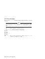
Table 2–2 SROM Memory Tests, CPU Jumper J1
Bank
#
6
Test Description
Test Results
Backup Cache Tag
Test
Test status displays on OCP:
1.2.3.done.
If the tests take longer than a few seconds between
each number displayed in the test count, there is a
problem with the cache—replace the CPU daughter board
(Chapter 6).
2
Cache Test: Tests
backup cache.
Test status displays on OCP:
....done.
If the test takes longer than a few seconds to complete,
there is a problem with the backup cache—replace the
CPU daughter board (Chapter 6).
4
Memory Test:
Tests memory with
backup and data
cache disabled.
Test status displays on OCP:
12345.done.
If an error is detected, the bank number and failing
SIMM position are displayed. The following OCP message
indicates a failing SIMM at bank 0, SIMM position 2.
FAIL B:0 S:2
Test duration: Approximately 10 seconds per 8 megabytes
of memory.
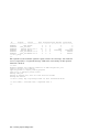
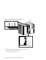
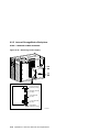
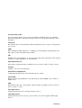
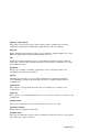
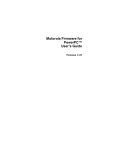
Figure 2–2 shows the bank and SIMM layout for
AlphaServer 1000 systems. After determining the bad
SIMM, refer to Chapter 6 for instructions on replacing
FRUs.
Note: The memory tests do not test the ECC SIMMs. If
the operating system logs five or more single-bit correctible
errors, swap the suspected ECC SIMMs with good SIMMs
and repeat the memory test.
(continued on next page)
2–4 Power-Up Diagnostics and Display
Table 2–2 (Cont.) SROM Memory Tests, CPU Jumper J1
Bank
#
5
Test Description
Test Results
Memory Test,
Cache Enabled:
Tests memory with
backup and data
cache enabled.
Test status displays on OCP:
12345.done.
If an error is detected, the bank number and failing
SIMM position are displayed. The following OCP message
indicates a failing SIMM at bank 0, SIMM position 2.
FAIL B:0 S:2
Test duration: Approximately 2 seconds per 8 megabytes
of memory.
Figure 2–2 shows the bank and SIMM layout for
AlphaServer 1000 systems. After determining the bad
SIMM, refer to Chapter 6 for instructions on replacing
FRUs.
Note: The memory tests do not test the ECC SIMMs. If
the operating system logs five or more single-bit correctible
errors, swap the suspected ECC SIMMs with good SIMMs
and repeat the memory test.
3
Backup Cache Test:
Tests backup cache
alternatively with
data cache enabled
then disabled.
Test status displays on OCP:
d
D
D
d
12345.done.
12345.done.
12345.done.
12345.done.
If an error is detected, the bank number and failing
SIMM position are displayed. The following OCP message
indicates a failing SIMM at bank 0, SIMM position 2.
FAIL B:0 S:2
Test duration: Approximately 2 seconds per 8 megabytes
of memory.
Figure 2–2 shows the bank and SIMM layout for
AlphaServer 1000 systems. After determining the bad
SIMM, refer to Chapter 6 for instructions on replacing
FRUs.
Note: The memory tests do not test the ECC SIMMs. If
the operating system logs five or more single-bit correctible
errors, swap the suspected ECC SIMMs with good SIMMs
and repeat the memory test.
Power-Up Diagnostics and Display 2–5
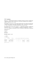
Figure 2–1 Jumper J1 on the CPU Daughter Board
J1
0
1
2
3
4
5
6
7
MA00328
Bank
Jumper Setting
0
Standard boot setting (default)
1
Mini-console setting: Internal use only
2
SROM CacheTest: backup cache test
3
SROM BCacheTest: backup cache and memory test
4
SROM memTest: memory test with backup and data cache disabled
5
SROM memTestCacheOn: memory test with backup and data cache enabled
6
SROM BCache Tag Test: backup cache tag test
7
Fail-Safe Loader setting: selects fail-safe loader firmware
2–6 Power-Up Diagnostics and Display
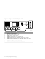
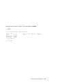
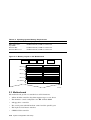
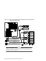
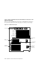
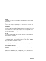
Figure 2–2 AlphaServer 1000 Memory Layout
Bank 3
Bank 2
Bank 1
Bank 0
ECC Banks
SIMM 1
SIMM 3
SIMM 0
SIMM 2
SIMM 1
SIMM 3
SIMM 0
SIMM 2
SIMM 1
SIMM 3
SIMM 0
SIMM 2
SIMM 1
SIMM 3
SIMM 0
SIMM 2
ECC SIMM for Bank 2
ECC SIMM for Bank 3
ECC SIMM for Bank 0
ECC SIMM for Bank 1
MA00327
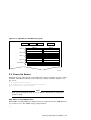
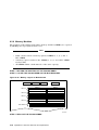
2.2 Power-Up Screen
During power-up self-tests, the test status and result are displayed on the console
terminal. Information similar to the following example should be displayed on
the screen.
ff.fe.fd.fc.fb.fa.f9.f8.f7.f6.f5.
ef.df.ee.f4.ed.ec.eb.....ea.e9.e8.e7.e6.e5.e4.e3.e2.e1.e0.
V1.1-1, built on Nov 4 1994 at 16:44:07
>>>
Note
If the power-up display stops on e6, an EISA or PCI board is causing the
system to hang.
DEC OSF/1 or OpenVMS Systems
DEC OSF/1 and OpenVMS operating systems are supported by the SRM firmware
(see Section 5.1.1). The SRM console prompt follows:
>>>
Power-Up Diagnostics and Display 2–7
Windows NT Systems
The Windows NT operating system is supported by the ARC firmware (see
Section 5.1.1). Systems using Windows NT power up to the ARC boot menu as
follows:
ARC Multiboot Alpha AXP Version n.nn
Copyright (c) 1994 Microsoft Corporation
Copyright (c) 1994 Digital Equipment Corporation
Boot menu:
Boot Windows NT
Boot an alternate operating system
Run a program
Supplementary menu...
Use the arrow keys to select, then press Enter.
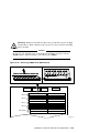
2.2.1 Console Event Log
AlphaServer 1000 systems maintain a console event log consisting of status
messages received during power-on self-tests. If problems occur during power-up,
standard error messages indicated by asterisks (***) may be embedded in the
console event log. To display a console event log, use the cat el command.
Note
To stop the screen display from scrolling, press
press Ctrl/Q .
Ctrl/S .
To resume scrolling,
You can also use the command, more el, to display the console event log
one screen at a time.
The following example shows a console event log that contains a standard error
message:
The keyboard is not plugged in or is not working.
>>> cat el
*** keyboard not plugged in...
ff.fe.fd.fc.fb.fa.f9.f8.f7.f6.f5.
ef.df.ee.f4.ed.ec.eb.ea.e9.e8.e7.e6.port pka0.7.0.6.0 initialized,
scripts are at 4f7faa0
resetting the SCSI bus on pka0.7.0.6.0
port pkb0.7.0.12.0 initialized, scripts are at 4f82be0
resetting the SCSI bus on pkb0.7.0.12.0
e5.e4.e3.e2.e1.e0.
V1.1-1, built on Nov 4 1994 at 16:44:07
device dka400.4.0.6.0 (RRD43) found on pka0.4.0.6.0
>>>
2–8 Power-Up Diagnostics and Display
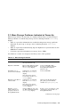
2.3 Mass Storage Problems Indicated at Power-Up
Mass storage failures at power-up are usually indicated by read fail messages.
Other problems are indicated by storage devices missing from the show config
display.
•
Table 2–3 provides information for troubleshooting mass storage problems
indicated at power-up or storage devices missing from the show config
display.
•
Table 2–4 provides troubleshooting tips for AlphaServer systems that use the
SWXCR-xx controller.
•
Section 2.4 provides information on storage device LEDs.
Use Tables 2–3 and 2–4 to diagnose the likely cause of the problem.
Table 2–3 Mass Storage Problems
Problem
Symptom
Corrective Action
Drive failure
Fault LED for drive is on
(steady) (Section 2.4).
Replace drive.
Duplicate SCSI IDs
Drives with duplicate SCSI
IDs are missing from the
show config display.
Correct SCSI IDs. May
need to reconfigure internal
StorageWorks backplane
(Section 5.8).
SCSI ID set to 7
(reserved for host ID)
Valid drives are missing
from the show config
display.
Correct SCSI IDs.
One drive may appear
seven times on the show
config display.
Duplicate host IDs on
a shared bus
Valid drives are missing
from the show config
display.
Change host ID through the
pk*0_host_id environment
variable (set pk*0_host_id).
One drive may appear
seven times on the show
config display.
Missing or loose
cables. Drives not
properly seated on
StorageWorks shelf
Activity LEDs do not come
on. Drive missing from the
show config display.
Remove device and inspect cable
connections. Reseat drive on
StorageWorks shelf.
(continued on next page)
Power-Up Diagnostics and Display 2–9
Table 2–3 (Cont.) Mass Storage Problems
Problem
Symptom
Corrective Action
SCSI bus length
exceeded
Drives may disappear
intermittently from the
show config and show
device displays.
A SCSI bus extended to the
internal StorageWorks shelf with
the backplane configured as a
single bus, cannot be extended
outside of the enclosure.
A SCSI bus extended to the
internal StorageWorks shelf with
the backplane configured as a
dual bus, can be extended 1
meter outside of the enclosure.
The entire SCSI bus length, from
terminator to terminator, must
not exceed 5 meters for singleended SCSI-2 at 5 MB/sec, or 3
meters for single-ended SCSI-2 at
10 MB/sec.
Terminator missing or
wrong terminator used
Read/write errors in the
console event log; storage
adapter port may fail.
Attach appropriate terminators
as needed (external SCSI
terminator for use with the
SWXCR-xx RAID controller,
12-41667-02; external SCSI
terminator for native controller,
12-37004-04 or 12-41667-02).
Note: The SCSI terminator
jumper (J49) on the system
motherboard should be set to
‘‘on’’ to enable the onboard SCSI
termination.
Extra terminator
Devices produce errors or
device IDs are dropped.
Check that bus is terminated only
at beginning and end. Remove
unnecessary terminators.
Note: The SCSI terminator
jumper (J49) on the system
motherboard should be set to
‘‘on’’ to enable the onboard SCSI
termination.
SCSI storage controller
failure
Problems persist after
eliminating the problem
sources.
2–10 Power-Up Diagnostics and Display
Replace failing EISA or PCI
storage adapter module (or
motherboard for the native SCSI
controller).
Table 2–4 Troubleshooting Problems with SWXCR-xx RAID Controller
Symptom
Action
Some RAID drives do not appear
on the show device d display.
Valid configured RAID logical drives will appear as
DRA0–DRAn, not as DKn. Configure the drives by
running the RAID Configuration Utility (RCU). Follow
the instructions in the StorageWorks RAID Array
200 Subsystem Family Installation and Configuration
Guide, EK-SWRA2-IG.
Reminder: Several physical disks can be grouped as a
single logical DRAn device.
External SCSI terminators used with the SWXCR
controller must be of the following type: 12-41667-02.
Drives on the SWXCR controller
power up with the amber Fault
light on.
Whenever you move drives onto or off of the SWXCR
controller, run the RAID Configuration Utility to set
up the drives and logical units. Follow the instructions
in the StorageWorks RAID Array 200 Subsystem
Family Installation and Configuration Guide.
External SCSI terminators used with the SWXCR
controller must be of the following type: 12-41667-02.
Image copy of DRA logical drive
does not boot (OpenVMS AXP
systems only).
If you copy the contents of a system disk to your RAID
subsystem using the BACKUP/IMAGE command, for
example, you will need to repeat several steps in the
data device installation procedure, as described in
the StorageWorks RAID Array 200 Subsystem Family
Software User’s Guide for OpenVMS AXP,
AA-Q6WVA-TE, in order to make the second device a
bootable device.
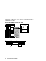
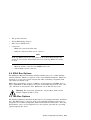
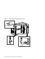
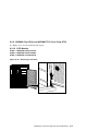
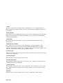
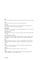
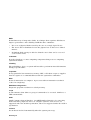
2.4 Storage Device LEDs
Storage device LEDs indicate the status of the device.
•
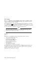
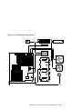
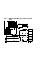
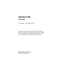
Figure 2–3 shows the LEDs for disk drives contained in a StorageWorks shelf.
A failure is indicated by the Fault light on each drive.
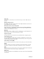
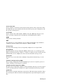
•
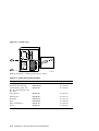
Figure 2–4 shows the Activity LED for the floppy drive. This LED is on when
the drive is in use.
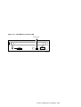
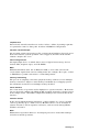
•
Figure 2–5 shows the Activity LED for the CD–ROM drive. This LED is on
when the drive is in use.
Power-Up Diagnostics and Display 2–11
For information on other storage devices, refer to the documentation provided by
the manufacturer or vendor.
Figure 2–3 StorageWorks Disk Drive LEDs (SCSI)
Activity
Fault
MA00329
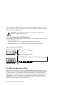
Figure 2–4 Floppy Drive Activity LED
Activity LED
2–12 Power-Up Diagnostics and Display
MA00330
Figure 2–5 CD–ROM Drive Activity LED
Activity LED
MA00333
Power-Up Diagnostics and Display 2–13
2.5 EISA Bus Problems Indicated at Power-Up
EISA bus failures at power-up are usually indicated by the following messages
displayed during power-up:
EISA Configuration Error. Run the EISA Configuration Utility.
Run the EISA Configuration Utility (ECU) (Section 5.4) when this message is
displayed. Other problems are indicated by EISA devices missing from the show
config display.
Table 2–5 provides steps for troubleshooting EISA bus problems that persist after
you run the ECU.
Table 2–5 EISA Troubleshooting
Step
Action
1
Confirm that the EISA module and any cabling are properly seated.
2
Run the ECU to:
•
Confirm that the system has been configured with the most recently installed
controller.
•
See what the hardware jumper and switch setting should be for each ISA
controller.
•
See what the software setting should be for each ISA and EISA controller.
•
See if the ECU deactivated (<>) any controllers to prevent conflict.
•
See if any controllers are locked (!), which limits the ECU’s ability to change
resource assignments.
3
Confirm that the hardware jumpers and switches on ISA controllers reflect the
settings indicated by the ECU. Start with the last ISA module installed.
4
Run ROM-based diagnostics for the type of option:
•
Storage adapter—Run test to exercise the storage devices off the EISA
controller option (Section 3.3.1).
•
Ethernet adapter—Run netew or
(Section 3.3.4, Section 3.3.5).
network to exercise an Ethernet adapter
5
Check for a bad slot by moving the last installed controller to a different slot.
6
Call the option manufacturer or support for help.
2–14 Power-Up Diagnostics and Display
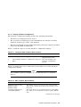
2.5.1 Additional EISA Troubleshooting Tips
The following tips can aid in isolating EISA bus problems.
•
Peripheral device controllers need to be seated (inserted) carefully, but firmly,
into their slot to make all necessary contacts. Improper seating is a common
source of problems for EISA modules.
•
Be sure you run the correct version of ECU for the operating system. For
windows NT, use ECU diskette DECpc AXP (AK-PYCJ*-CA); for DEC OSF/1
and OpenVMS, use ECU diskette DECpc AXP (AK-Q2CR*-CA).
•
The CFG files supplied with the option you want to install may not work on
AlphaServer 1000 systems. Some CFG files call overlay files that are not
required on this system or may reference inappropriate system resources, for
example, BIOS addresses. Contact the option vendor to obtain the proper
CFG file.
•
Peripherals cannot share direct memory access (DMA) channels. Assignment
of more than one peripheral to the same DMA channel can cause
unpredictable results or even loss of function of the EISA module.
•
Systems running Windows NT can assign shared interrupt lines (IRQs). DEC
OSF/1 and OpenVMS do not allow shared interrupts.
•
Not all EISA products work together. EISA is an open standard, and not
every EISA product or combination of products can be tested. Violations of
specifications may matter in some configurations, but not in others.
Manufacturers of EISA options often test the most common combinations and
may have a list of ISA and EISA options that do not function in combination
with particular systems. Be sure to check the documentation or contact the
option vendor for the most up-to-date information.
•
EISA systems will not function unless they are first configured using the
ECU.
•
The ECU will not notify you if the configuration program diskette is writeprotected when it attempts to write the system configuration file (system.sci)
to the diskette.
Power-Up Diagnostics and Display 2–15
2.6 PCI Bus Problems Indicated at Power-Up
PCI bus failures at power-up are usually indicated by the inability of the system
to see the device. Table 2–6 provides steps for troubleshooting PCI bus problems.
Use the table to diagnose the likely cause of the problem.
Note
Some PCI devices do not implement PCI parity, and some have a paritygenerating scheme in which parity is sometimes incorrect or is not
compliant with the PCI Specification. In such cases, the device functions
properly as long as parity is not checked. The pci_parity environment
variable for the SRM console, or the DISABLEPCIPARITY CHECKING
for the ARC console, allow you to turn off parity checking so that false
PCI parity errors do not result in machine check errors.
When you disable PCI parity, no parity checking is implemented for any
PCI device, even those devices that produce correct, compliant parity.
Table 2–6 PCI Troubleshooting
Step
Action
1
Confirm that the PCI module and any cabling are properly seated.
2
Run ROM-based diagnostics for the type of option:
•
Storage adapter—Run test to exercise the storage devices off the PCI
controller option (Section 3.3.1).
•
Ethernet adapter—Run netew or
(Section 3.3.4, Section 3.3.5).
network to exercise an Ethernet adapter
3
Check for a bad slot by moving the last installed controller to a different slot.
4
Call the option manufacturer or support for help.
2–16 Power-Up Diagnostics and Display
2.7 Fail-Safe Loader
The fail-safe loader (FSL) allows you to attempt to recover when one of the
following is the cause of a problem getting to the console program under normal
power-up:
•
A power failure or accidental power down during a firmware upgrade
•
A checksum failure or flash ROM header error while the SROM code is trying
to load the SRM/ARC console firmware
Note
The fail-safe loader should be used only when a failure at power-up
prohibits you from getting to the console program. You cannot boot an
operating system from the fail-safe loader.
If a checksum error is detected when the SRM/ARC console is loading at
power-up (error beep code 1-1-4), you need to activate the fail-safe loader
and reinstall the firmware.
2.7.1 Fail-Safe Loader Functions
From the FSL program, you can update or load new console firmware.
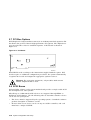
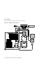
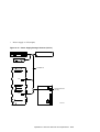
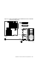
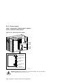
2.7.2 Activating the Fail-Safe Loader
To activate the FSL:
1. Install the jumper at bank 7 of the J1 jumper on the CPU daughter board
(Figure 2–6). The jumper is normally installed in the standard boot setting
(bank 0).
2. Install the console firmware floppy diskette and turn on the system.
3. Reinstall the console firmware from a firmware diskette.
4. When you have finished, power down and return the J1 jumper to the
standard boot setting (bank 0).
Power-Up Diagnostics and Display 2–17
Figure 2–6 Jumper J1 on the CPU Daughter Board
J1
0
1
2
3
4
5
6
7
MA00328
Bank
Jumper Setting
0
Standard boot setting (default)
1
Mini-console setting: Internal use only
2
SROM CacheTest: backup cache test
3
SROM BCacheTest: backup cache and memory test
4
SROM memTest: memory test with backup and data cache disabled
5
SROM memTestCacheOn: memory test with backup and data cache enabled
6
SROM BCache Tag Test: backup cache tag test
7
Fail-Safe Loader setting: selects fail-safe loader firmware
2–18 Power-Up Diagnostics and Display
2.8 Power-Up Sequence
During the AlphaServer 1000 power-up sequence, the power supplies are
stabilized and the system is initialized and tested through the firmware power-on
self-tests.
The power-up sequence includes the following:
•
•
Power supply power-up:
–
AC power-up
–
DC power-up
Two sets of power-on diagnostics:
–
Serial ROM diagnostics
–
Console firmware-based diagnostics
Caution
The AlphaServer 1000 enclosure will not power up if the top cover is not
securely attached. Removing the top cover will cause the system to shut
down.
2.8.1 AC Power-Up Sequence
The following power-up sequence occurs when AC power is applied to the system
(system is plugged in) or when electricity is restored after a power outage:
1. The front end of the power supply begins operation and energizes.
2. The power supply then waits for the DC power to be enabled.
Note
The top cover and side panels must be securely installed. A safety
interlock prevents the system from being powered on with the cover and
panels removed.
Power-Up Diagnostics and Display 2–19
2.8.2 DC Power-Up Sequence
DC power is applied to the system with the DC On/Off button on the operator
control panel.
A summary of the DC power-up sequence follows:
1. When the DC On/Off button is pressed, the power supply checks for a POK_H
condition.
2. 12V, 5V, 3.3V, and -12V outputs are energized and stabilized. If the outputs
do not come into regulation, the power-up is aborted and the power supply
enters the latching-shutdown mode.
2.9 Firmware Power-Up Diagnostics
After successful completion of AC and DC power-up sequences, the processor
performs its power-up diagnostics. These tests verify system operation, load
the system console, and test the core system (CPU, memory, and motherboard),
including all boot path devices. These tests are performed as two distinct sets of
diagnostics:
1. Serial ROM diagnostics—These tests are loaded from the serial ROM located
on the CPU daughter board into the CPU’s instruction cache (I-cache). The
tests check the basic functionality of the system and load the console code
from the FEPROM on the motherboard into system memory.
Failures during these tests are indicated by audible error beep codes. Failures
of customized SROM tests, set using the J1 jumper on the CPU daughter
board, are displayed on the operator control panel.
2. Console firmware-based diagnostics—These tests are executed by the console
code. They test the core system, including all boot path devices.
Failures during these tests are reported to the console terminal through the
power-up screen or console event log.
2.9.1 Serial ROM Diagnostics
The serial ROM diagnostics are loaded into the CPU’s instruction cache from the
serial ROM on the CPU daughter board. The diagnostics test the system in the
following order:
1. Test the CPU and backup cache located on the CPU daughter board.
2. Test the CPU module’s system bus interface.
3. Test the system bus to PCI bus bridge and system bus to EISA bus bridge. If
the PCI bridge fails or EISA bridge fails, an audible error beep code sounds.
The power-up tests continue despite these errors.
2–20 Power-Up Diagnostics and Display
4. Configure the memory in the system and test only the first 4 MB of memory.
If there is more than one memory module of the same size, the lowest
numbered memory module (one closest to the CPU) is tested first.
If the memory test fails, the failing bank is mapped out and memory is
reconfigured and re-tested. Testing continues until good memory is found. If
good memory is not found, an error beep code (1-3-3) is generated and the
power-up tests are terminated.
5. Check the data path to the FEPROMs on the motherboard.
6. The console program is loaded into memory from the FEPROM on the
motherboard. A checksum test is executed for the console image. If the
checksum test fails, an error beep code (1-1-4) is generated and the power-up
tests are terminated.
If the checksum test passes, control is passed to the console code, and the
console firmware-based diagnostics are run.
2.9.2 Console Firmware-Based Diagnostics
Console firmware-based tests are executed once control is passed to the console
code in memory. They check the system in the following order:
1. Perform a complete check of system memory.
Steps 2–5 may be completed in parallel.
2. Start the I/O drivers for mass storage devices and tapes. At this time a
complete functional check of the machine is made. After the I/O drivers
are started, the console program continuously polls the bus for devices
(approximately every 20 or 30 seconds).
3. Check that EISA configuration information is present in NVRAM for each
EISA module detected and that no information is present for modules that
have been removed.
4. Run exercisers on the drives currently seen by the system.
Note
This step does not ensure that all disks in the system will be tested or
that any device drivers will be completely tested. Spin-up time varies
for different drives, so not all disks may be on line at this point in the
power-up sequence. To ensure complete testing of disk devices, use the
test command (Section 3.3.1).
Power-Up Diagnostics and Display 2–21
5. Enter console mode or boot the operating system. This action is determined
by the auto_action environment variable.
If the os_type environment variable is set to NT, the ARC console is loaded
into memory, and control is passed to the ARC console.
2–22 Power-Up Diagnostics and Display
3
Running System Diagnostics
This chapter provides information on how to run system diagnostics.
•
Section 3.1 describes how to run ROM-based diagnostics, including error
reporting utilities and loopback tests.
•
Section 3.4 describes acceptance testing and initialization procedures.
•
Section 3.5 describes the DEC VET operating system exerciser.
3.1 Running ROM-Based Diagnostics
ROM-based diagnostics (RBDs), which are part of the console firmware that
is loaded from the FEPROM on the system motherboard, offer many powerful
diagnostic utilities, including the ability to examine error logs from the console
environment and run system- or device-specific exercisers.
AlphaServer 1000 RBDs rely on exerciser modules, rather than functional tests,
to isolate errors. The exercisers are designed to run concurrently, providing a
maximum bus interaction between the console drivers and the target devices.
The multitasking ability of the console firmware allows you to run diagnostics in
the background (using the background operator ‘‘&’’ at the end of the command).
You run RBDs by using console commands.
Note
ROM-based diagnostics, including the test command, are run from the
SRM console (firmware used by OpenVMS and DEC OSF/1 systems). If
you are running a Windows NT system, refer to Section 5.1.2 for the steps
used to switch between consoles.
RBDs report errors to the console terminal and/or the console event log.
Running System Diagnostics 3–1
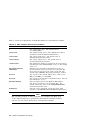
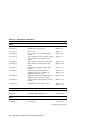
3.2 Command Summary
Table 3–1 provides a summary of the diagnostic and related commands.
Table 3–1 Summary of Diagnostic and Related Commands
Command
Function
Reference
Acceptance Testing
test
Quickly tests the core system. The test command
is the primary diagnostic for acceptance testing and
console environment diagnosis.
Section 3.3.1
cat el
Displays the console event log.
Section 3.3.2
more el
Displays the console event log one screen at a time.
Section 3.3.2
Error Reporting
Extended Testing/Troubleshooting
memory
Runs memory exercises each time the command is
entered. These exercises run concurrently in the
background.
Section 3.3.3
net -ic
Initializes the MOP counters for the specified
Ethernet port.
Section 3.3.7
net -s
Displays the MOP counters for the specified
Ethernet port.
Section 3.3.6
netew
Runs external mop loopback tests for specified EISAor PCI-based ew* (DECchip 21040, TULIP) Ethernet
ports.
Section 3.3.4
network
Runs external mop loopback tests for specified EISAor PCI-based er* (DEC 4220, LANCE) Ethernet
ports.
Section 3.3.5
(continued on next page)
3–2 Running System Diagnostics
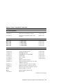
Table 3–1 (Cont.) Summary of Diagnostic and Related Commands
Command
Function
Reference
test lb
Conducts loopback tests for COM2 and the parallel
port in addition to quick core system tests.
Section 3.3.1
netew
Runs external mop loopback tests for specified EISAor PCI-based ew* (DECchip 21040, TULIP) Ethernet
ports.
Section 3.3.4
network
Runs external mop loopback tests for specified EISAor PCI-based er* (DEC 4220, LANCE) Ethernet
ports.
Section 3.3.5
Loopback Testing
Diagnostic-Related Commands
kill
Terminates a specified process.
Section 3.3.8
kill_diags
Terminates all currently executing diagnostics.
Section 3.3.8
show_status
Reports the status of currently executing test
/exercisers.
Section 3.3.9
3.3 Command Reference
This section provides detailed information on the diagnostic commands and
related commands.
Running System Diagnostics 3–3
3.3.1 test
The test command runs firmware diagnostics for the entire core system. The
tests are run concurrently in the background. Fatal errors are reported to the
console terminal.
The cat el command should be used in conjunction with the test command to
examine test/error information reported to the console event log.
Because the tests are run concurrently and indefinitely (until you stop them with
the kill_diags command), they are useful in flushing out intermittent hardware
problems.
Note
By default, no write tests are performed on disk and tape drives. Media
must be installed to test the floppy drive and tape drives. A loopback
connector is required for the COM2 (9-pin loopback connector, 12-2735101) port.
To terminate the tests, use the kill command to terminate an individual
diagnostic or the kill_diags command to terminate all diagnostics. Use the
show_status display to determine the process ID when terminating an individual
diagnostic test.
Note
A serial loopback connector (12-27351-01) must be installed on the COM2
serial port for the kill_diags command to successfully terminate system
tests.
The test script tests devices in the following order:
1. Console loopback tests if lb argument is specified: COM2 serial port and
parallel port.
2. Network external loopback tests for E*A0. This test requires that the
Ethernet port be terminated or connected to a live network; otherwise, the
test will fail.
3. Memory tests (one pass).
4. Read-only tests: DK* disks, DR* disks, DU* disks, MK* tapes, DV* floppy.
3–4 Running System Diagnostics
5. VGA console tests. These tests are run only if the console environment
variable is set to ‘‘serial.’’ The VGA console test displays rows of the letter
‘‘H’’.
Synopsis:
test [lb]
Argument:
[lb]
The loopback option includes console loopback tests for the COM2 serial
port and the parallel port during the test sequence.
Examples:
The system is tested and the tests complete successfully.
Note
Examine the console event log after running tests.
>>> test
Requires diskette and loopback connectors on COM2 and parallel port
type kill_diags to halt testing
type show_status to display testing progress
type cat el to redisplay recent errors
Testing COM2 port
Setting up network test, this will take about 20 seconds
Testing the network
48 Meg of System Memory
Bank 0 = 16 Mbytes(4 MB Per Simm) Starting at 0x00000000
Bank 1 = 16 Mbytes(4 MB Per Simm) Starting at 0x01000000
Bank 2 = 16 Mbytes(4 MB Per Simm) Starting at 0x02000000
Bank 3 = No Memory Detected
Testing the memory
Testing parallel port
Testing the SCSI Disks
Non-destructive Test of the Floppy starteddka400.4.0.6.0 has no media
present or is disabled via the RUN/STOP switch
file open failed for dka400.4.0.6.0
Testing the VGA(Alphanumeric Mode only)
Printer offline
file open failed for para
>>> show_status
Running System Diagnostics 3–5
ID
Program
-------- -----------00000001
idle
0000002d
exer_kid
0000003d
nettest
00000045
memtest
00000052
exer_kid
00000053
exer_kid
>>> kill_diags
>>>
Device
Pass Hard/Soft Bytes Written Bytes Read
------------ ------ --------- ------------- ------------system
0
0
0
0
0
tta1
0
0
0
1
0
era0.0.0.2.1
43
0
0
1376
1376
memory
7
0
0
424673280
424673280
dka100.1.0.6
0
0
0
0
2688512
dka200.2.0.6
0
0
0
0
922624
The system is tested and the system reports a fatal error message. No network
server responded to a loopback message. Ethernet connectivity on this system
should be checked.
>>> test
Requires diskette and loopback connectors on COM2 and parallel port
type kill_diags to halt testing
type show_status to display testing progress
type cat el to redisplay recent errors
Testing COM2 port
Setting up network test, this will take about 20 seconds
Testing the network
*** Error (era0), Mop loop message timed out from: 08-00-2b-3b-42-fd
*** List index: 7 received count: 0 expected count 2
>>>
3–6 Running System Diagnostics
3.3.2 cat el and more el
The cat el and more el commands display the current contents of the console
event log. Status and error messages (if problems occur) are logged to the console
event log at power-up, during normal system operation, and while running system
tests.
Standard error messages are indicated by asterisks (***).
When cat el is used, the contents of the console event log scroll by. You can use
the Ctrl/S combination to stop the screen from scrolling, Ctrl/Q to resume scrolling.
The more el command allows you to view the console event log one screen at a
time.
Synopsis:
cat el
or
more el
Examples:
The following examples show abbreviated console event logs that contain
standard error messages:
The first error message indicates the keyboard is not plugged in or is not
working.
>>> cat el
*** keyboard not plugged in...
ff.fe.fd.fc.fb.fa.f9.f8.f7.f6.f5.
ef.df.ee.f4.ed.ec.eb.ea.e9.e8.e7.e6.port pka0.7.0.6.0 initialized,
scripts are at 4f7faa0
resetting the SCSI bus on pka0.7.0.6.0
port pkb0.7.0.12.0 initialized, scripts are at 4f82be0
resetting the SCSI bus on pkb0.7.0.12.0
e5.e4.e3.e2.e1.e0.
V1.1-1, built on Nov 4 1994 at 16:44:07
device dka400.4.0.6.0 (RRD43) found on pka0.4.0.6.0
>>>
Running System Diagnostics 3–7
3.3.3 memory
The memory command tests memory by running a memory exerciser each time the
command is entered. The exercisers are run in the background and nothing is
displayed unless an error occurs.
The number of exercisers, as well as the length of time for testing, depends on the
context of the testing. Generally, running three to five exercisers for 15 minutes
to 1 hour is sufficient for troubleshooting most memory problems.
To terminate the memory tests, use the kill command to terminate an individual
diagnostic or the kill_diags command to terminate all diagnostics. Use the
show_status display to determine the process ID when terminating an individual
diagnostic test.
Synopsis:
memory
Examples:
Example with no errors.
>>>
>>>
>>>
>>>
memory
memory
memory
show_status
ID
Program
-------- -----------00000001
idle
0000006b
memtest
00000071
memtest
00000077
memtest
>>> kill_diags
>>>
Device
Pass Hard/Soft Bytes Written Bytes Read
------------ ------ --------- ------------- ------------system
0
0
0
0
0
memory
1
0
0
53477376
53477376
memory
1
0
0
31457280
31457280
memory
1
0
0
24117248
24117248
3–8 Running System Diagnostics
Example with a memory compare error indicating bad SIMMs.
>>> memory
>>> memory
>>> memory
*** Hard Error - Error #44 - Memory compare error
Diagnostic Name
memtest
Expected value:
Received value:
Failing addr:
ID
000000c8
00000004
80000001
800001c
Device Pass Test Hard/Soft
brd0
1
1
1
0
1-JAN-2066
12:00:01
*** End of Error ***
>>> kill_diags
>>>
Running System Diagnostics 3–9
3.3.4 netew
The netew command is used to run MOP loopback tests for any EISA- or PCIbased ew* (DECchip 21040, TULIP) Ethernet ports. The command can also be
used to test a port on a ‘‘live’’ network.
The loopback tests are set to run continuously (-p pass_count set to 0). Use the
kill command (or Ctrl/C ) to terminate an individual diagnostic or the kill_diags
command to terminate all diagnostics. Use the show_status display to determine
the process ID when terminating an individual diagnostic test.
Note
While some results of network tests are reported directly to the console,
you should examine the console event log (using the cat el or more el
commands) for complete test results.
Synopsis:
netew
When the netew command is entered, the following script is executed:
net -sa ew*0>ndbr/lp_nodes_ew*0
set ew*0_loop_count 2 2>nl
set ew*0_loop_inc 1 2>nl
set ew*0_loop_patt ffffffff 2>nl
set ew*0_loop_size 10 2>nl
set ew*0_lp_msg_node 1 2>nl
net -cm ex ew*0
echo "Testing the network"
nettest ew*0 -sv 3 -mode nc -p 0 -w 1 &
The script builds a list of nodes for which to send MOP loopback packets, sets
certain test environment variables, and tests the Ethernet port by using the
following variation of the nettest exerciser:
nettest ew*0 -sv 3 -mode nc -p 0 -w 1 &
3–10 Running System Diagnostics
Testing an Ethernet Port:
>>> netew
>>> show_status
ID
Program
-------- -----------00000001
idle
000000d5
nettest
>>> kill_diags
>>>
Device
Pass Hard/Soft Bytes Written Bytes Read
------------ ------ --------- ------------- ------------system
0
0
0
0
0
ewa0.0.0.0.0
13
0
0
308672
308672
Running System Diagnostics 3–11
3.3.5 network
The network command is used to run MOP loopback tests for any EISA- or PCIbased er* (DEC 4220, LANCE) Ethernet ports. The command can also be used to
test a port on a ‘‘live’’ network.
The loopback tests are set to run continuously (-p pass_count set to 0). Use the
Ctrl/C ) to terminate an individual diagnostic or the kill_diags
command to terminate all diagnostics. Use the show_status display to determine
the process ID when terminating an individual diagnostic test.
kill command (or
Note
While some results of network tests are reported directly to the console,
you should examine the console event log (using the cat el or more el
commands) for complete test results.
Synopsis:
network
When the network command is entered, the following script is executed:
echo "setting up the network test, this will take about 20 seconds"
net -stop er*0
net -sa er*0>ndbr/lp_nodes_er*0
net ic er*0
set er*0_loop_count 2 2>nl
set er*0_loop_inc 1 2>nl
set er*0_loop_patt ffffffff 2>nl
set er*0_loop_size 10 2>nl
set er*0_lp_msg_node 1 2>nl
set er*0_mode 44 2>nl
net -start er*0
echo "Testing the network"
nettest er*0 -sv 3 -mode nc -p 0 -w 1 &
The script builds a list of nodes for which to send MOP loopback packets, sets
certain test environment variables, and tests the Ethernet port by using the
following variation of the nettest exerciser:
nettest er*0 -sv 3 -mode nc -p 0 -w 1 &
3–12 Running System Diagnostics
Testing an Ethernet Port:
>>> network
>>> show_status
ID
Program
-------- -----------00000001
idle
000000d5
nettest
>>> kill_diags
>>>
Device
Pass Hard/Soft Bytes Written Bytes Read
------------ ------ --------- ------------- ------------system
0
0
0
0
0
era0.0.0.0.0
13
0
0
308672
308672
Running System Diagnostics 3–13
3.3.6 net -s
The net -s command displays the MOP counters for the specified Ethernet port.
Synopsis:
net -s ewa0
Example:
>>> net -s ewa0
Status
ti: 72
rps: 0
tto: 1
counts:
tps: 0 tu: 47 tjt: 0 unf: 0 ri: 70 ru: 0
rwt: 0 at: 0 fd: 0 lnf: 0 se: 0 tbf: 0
lkf: 1 ato: 1 nc: 71 oc: 0
MOP BLOCK:
Network list size: 0
MOP COUNTERS:
Time since zeroed (Secs): 42
TX:
Bytes: 0 Frames: 0
Deferred: 1 One collision: 0 Multi collisions: 0
TX Failures:
Excessive collisions: 0 Carrier check: 0 Short circuit: 71
Open circuit: 0 Long frame: 0 Remote defer: 0
Collision detect: 71
RX:
Bytes: 49972 Frames: 70
Multicast bytes: 0 Multicast frames: 0
RX Failures:
Block check: 0 Framing error: 0 Long frame: 0
Unknown destination: 0 Data overrun: 0 No system buffer: 0
No user buffers: 0
>>>
3–14 Running System Diagnostics
3.3.7 net -ic
The net -ic command initializes the MOP counters for the specified Ethernet
port.
Synopsis:
net -ic ewa0
Example:
>>> net -ic ewa0
>>> net -s ewa0
Status counts:
ti: 72 tps: 0 tu: 47 tjt: 0 unf: 0 ri: 70 ru: 0
rps: 0 rwt: 0 at: 0 fd: 0 lnf: 0 se: 0 tbf: 0
tto: 1 lkf: 1 ato: 1 nc: 71 oc: 0
MOP BLOCK:
Network list size: 0
MOP COUNTERS:
Time since zeroed (Secs): 3
TX:
Bytes: 0 Frames: 0
Deferred: 0 One collision: 0 Multi collisions: 0
TX Failures:
Excessive collisions: 0 Carrier check: 0 Short circuit: 0
Open circuit: 0 Long frame: 0 Remote defer: 0
Collision detect: 0
RX:
Bytes: 0 Frames: 0
Multicast bytes: 0 Multicast frames: 0
RX Failures:
Block check: 0 Framing error: 0 Long frame: 0
Unknown destination: 0 Data overrun: 0 No system buffer: 0
No user buffers: 0
>>>
Running System Diagnostics 3–15
3.3.8 kill and kill_diags
The kill and kill_diags commands terminate diagnostics that are currently
executing .
Note
A serial loopback connector (12-27351-01) must be installed on the COM2
serial port for the kill_diags command to successfully terminate system
tests.
•
The kill command terminates a specified process.
•
The kill_diags command terminates all diagnostics.
Synopsis:
kill_diags
kill [PID . . . ]
Argument:
[PID . . . ]
The process ID of the diagnostic to terminate. Use the
command to determine the process ID.
3–16 Running System Diagnostics
show_status
3.3.9 show_status
The show_status command reports one line of information per executing
diagnostic. The information includes ID, diagnostic program, device under
test, error counts, passes completed, bytes written, and bytes read.
Many of the diagnostics run in the background and provide information only
if an error occurs. Use the show_status command to display the progress of
diagnostics.
The following command string is useful for periodically displaying diagnostic
status information for diagnostics running in the background:
>>> while true;show_status;sleep n;done
Where n is the number of seconds between show_status displays.
Synopsis:
show_status
Example:
>>> show_status
>>>show_status
ID
Program
-------- -----------00000001
idle
0000002d
exer_kid
0000003d
nettest
00000045
memtest
00000052
exer_kid
>>>
Device
Pass Hard/Soft Bytes Written Bytes Read
------------ ------ --------- ------------- ------------system
0
0
0
0
0
tta1
0
0
0
1
0
era0.0.0.2.1
43
0
0
1376
1376
memory
7
0
0
424673280
424673280
dka100.1.0.6
0
0
0
0
2688512
Process ID
Program module name
Device under test
Diagnostic pass count
Error count (hard and soft): Soft errors are not usually fatal; hard errors halt
the system or prevent completion of the diagnostics.
Bytes successfully written by diagnostic
Bytes successfully read by diagnostic
Running System Diagnostics 3–17
3.4 Acceptance Testing and Initialization
Perform the acceptance testing procedure listed below after installing a system or
whenever adding or replacing the following:
Memory modules
Motherboard
CPU daughter board
Storage devices
EISA or PCI options
1. Run the RBD acceptance tests using the test command.
2. If you have added, moved, or removed an EISA or ISA option, run the EISA
Configuration Utility (ECU).
3. Bring up the operating system.
4. Run DEC VET to test that the operating system is correctly installed. Refer
to Section 3.5 for information on DEC VET.
3.5 DEC VET
Digital’s DEC Verifier and Exerciser Tool (DEC VET) software is a multipurpose
system maintenance tool that performs exerciser-oriented maintenance testing.
DEC VET runs on OpenVMS AXP, DEC OSF/1, and Windows NT operating
systems. DEC VET consists of a manager and exercisers. The DEC VET
manager controls the exercisers. The exercisers test system hardware and the
operating system.
DEC VET supports various exerciser configurations, ranging from a single device
exerciser to full system loading, that is, simultaneous exercising of multiple
devices.
Refer to the DEC Verifier and Exerciser Tool User’s Guide (AA–PTTMA–TE) for
instructions on running DEC VET.
3–18 Running System Diagnostics
4
Error Log Analysis
This chapter provides information on how to interpret error logs reported by the
operating system.
•
Section 4.1 describes machine check/interrupts and how these errors are
detected and reported.
•
Section 4.2 describes the entry format used by the error formatters.
•
Section 4.3 describes how to generate a formatted error log using the
DECevent Translation and Reporting Utility available with OpenVMS and
Digital UNIX.
4.1 Fault Detection and Reporting
Table 4–1 provides a summary of the fault detection and correction components of
AlphaServer 1000 systems.
Generally, PALcode handles exceptions as follows:
•
The PALcode determines the cause of the exception.
•
If possible, it corrects the problem and passes control to the operating system
for reporting before returning the system to normal operation.
•
If error/event logging is required, control is passed through the system control
block (SCB) to the appropriate exception handler.
Error Log Analysis 4–1
Table 4–1 AlphaServer 1000 Fault Detection and Correction
Component
Fault Detection/Correction Capability
KN22A Processor Module
DECchip 21064 and 21064A
microprocessors
Contains error detection and correction (EDC) logic for
data cycles. There are check bits associated with all data
entering and exiting the 21064(A) microprocessor. A singlebit error on any of the four longwords being read can be
corrected (per cycle). A double-bit error on any of the four
longwords being read can be detected (per cycle).
Backup cache (B-cache)
EDC check bits on the data store, and parity on the tag
address store and tag control store.
Memory Subsystem
Memory SIMMs
EDC logic protects data by detecting and correcting data
cycle errors. A single-bit on any of the four longwords can
be corrected (per cycle). A double-bit error on any of the
four longwords being read can be detected (per cycle).
System Motherboard
SCSI Controller
SCSI data parity is generated.
EISA-to-PCI bridge chip
PCI data parity is generated.
4.1.1 Machine Check/Interrupts
The exceptions that result from hardware system errors are called machine
check/interrupts. They occur when a system error is detected during the
processing of a data request. There are four types of machine check/interrupts
related to system events:
1. Processor machine check (SCB 670)
2. System machine check (SCB 660)
3. Processor-corrected machine check (SCB 630)
4. System-corrected machine check (SCB 620)
During the error handling process, errors are first handled by the appropriate
PALcode error routine and then by the associated operating system error handler.
The causes of each of the machine check/interrupts are as follows. The system
control block (SCB) vector through which PALcode transfers control to the
operating system is shown in parentheses.
4–2 Error Log Analysis
Processor Machine Check (SCB: 670)
Processor machine check errors are fatal system errors that result in a system
crash. The error handling code for these errors are common across all platforms
using the DECchip 21064 and 21064A microprocessors.
•
The DECchip 21064 or 21064A microprocessor detected one or more of the
following uncorrectable data errors:
–
Uncorrectable B-cache data error
–
Uncorrectable memory data error
•
A B-cache tag or tag control parity error occurred
•
Hard error was asserted in response to:
–
Double-bit Istream ECC error
–
Double-bit Dstream ECC error
–
System transaction terminated with CACK_HERR
–
I-cache parity errors
–
D-cache parity errors
System Machine Check (SCB: 660)
A system machine check is a system-detected error, external to the DECchip
21064 microprocessor and possibly not related to the activities of the CPU. These
errors are specific to AlphaServer 1000 systems.
Fatal errors:
•
System overtemperature failure
•
System complete power supply failure
•
System fan failure
•
I/O read/write retry timeout
•
DMA data parity error
•
I/O data parity error
•
Slave abort PCI transaction
•
DEVSEL not asserted
•
Uncorrectable read error
•
Invalid page table lookup (scatter gather)
•
Memory cycle error
Error Log Analysis 4–3
•
B-cache tag address parity error
•
B-cache tag control parity error
•
Non-existent memory error
•
ESC NMI: IOCHK
Processor-Corrected Machine Check (SCB: 630)
Processor-corrected machine checks are caused by B-cache errors that are
detected and corrected by the DECchip 21064 or 21064A microprocessor. These
are nonfatal errors that result in an error log entry. The error handling code
for these errors are common across all platforms using the DECchip 21064 and
21064A microprocessors.
•
Single-bit Istream ECC error
•
Single-bit Dstream ECC error
•
System transaction terminated with CACK_SERR
System Machine Check (SCB: 620)
These errors (non-fatal) are AlphaServer 1000-specific correctable errors. These
errors result in the generation of the correctable machine check logout frame:
•
Correctable read errors
•
Single power supply failure when operating with redundant power supplies.
•
System overtemperature warning
4.2 Error Logging and Event Log Entry Format
The Digital UNIX and OpenVMS error handlers can generate several entry types.
All error entries, with the exception of correctable memory errors, are logged
immediately. Entries can be of variable length based on the number of registers
within the entry.
Each entry consists of an operating system header, several device frames, and an
end frame. Most entries have a PAL-generated logout frame, and may contain
frames for CPU, memory, and I/O.
4–4 Error Log Analysis
4.3 Event Record Translation
Systems running Digital UNIX and OpenVMS operating systems use the
DECevent management utility to translate events into ASCII reports derived
from system event entries (bit-to-text translations).
The DECevent utility has the following features relating to the translation of
events:
•
Translating event log entries into readable reports
•
Selecting input and output sources
•
Filtering input events
•
Selecting alternate reports
•
Translating events as they occur
•
Maintaining and customizing the user environment with the interactive shell
commands
Note
Microsoft Windows NT does not currently provide bit-to-text translation
of system errors.
•
Section 4.3.1 summarizes the command used to translate the error log
information for the OpenVMS operating system using DECevent.
•
Section 4.3.2 summarizes the command used to translate the error log
information for the Digital UNIX operating system using DECevent.
4.3.1 OpenVMS Translation Using DECevent
The kernel error log entries are translated from binary to ASCII using the
DIAGNOSE command. To invoke the DECevent utility, enter the DCL command
DIAGNOSE.
Format:
DIAGNOSE/TRANSLATE [qualifier] [, . . . ] [infile[, . . . ]]
Example:
$ DIAGNOSE/TRANSLATE/SINCE=14-JUN-1995
For more information on generating error log reports using DECevent, refer to
DECevent Translation and Reporting Utility for OpenVMS User and Reference
Guide.
Error Log Analysis 4–5
4.3.2 Digital UNIX Translation Using DECevent
The kernel error log entries are translated from binary to ASCII using the dia
command. To invoke the DECevent utility, enter dia command.
Format:
dia [-a -f infile[ . . . ]]
Example:
% dia -t s:14-jun-1995:10:00
For more information on generating error log reports using DECevent, refer to
DECevent Translation and Reporting Utility for Digital UNIX User and Reference
Guide.
4–6 Error Log Analysis
5
System Configuration and Setup
This chapter provides configuration and setup information for AlphaServer 1000
systems and system options.
•
Section 5.1 describes how to examine the system configuration using the
console firmware.
–
Section 5.1.1 describes the function of the two firmware interfaces used
with AlphaServer 1000 systems.
–
Section 5.1.2 describes how to switch between firmware interfaces.
–
Sections 5.1.3 and 5.1.4 describe the commands used to examine system
configuration for each firmware interface.
•
Section 5.2 describes the system bus configuration.
•
Section 5.3 describes the motherboard.
•
Section 5.4 describes the EISA bus.
•
Section 5.5 describes how ISA options are compatible on the EISA bus.
•
Section 5.6 describes the EISA configuration utility (ECU).
•
Section 5.7 describes the PCI bus.
•
Section 5.8 describes SCSI buses and configurations.
•
Section 5.9 describes power supply configurations.
•
Section 5.10 describes the console port configurations.
System Configuration and Setup 5–1
5.1 Verifying System Configuration
Figure 5–1 illustrates the system architecture for AlphaServer 1000 systems.
Figure 5–1 System Architecture: AlphaServer 1000
CPU Card
SROM
21064
Bcache
2MB
PCI-EISA
Bridge
Buffers
Flash
ROM
EISA Slots
EISA Slots
OCP
PCI Slots
EISA Slots
PCI Slots
EISA Slots
Real
Time
Clock
PCI Slots
EISA Slots
NCR
810
EISA Slots
EISA
Config
RAM
Epic
Comanche
Decade
8242
Keybd &
Mouse
EISA Slots
EISA Slots
SCSI Bus
Memory
(16MB-1GB)
X-Bus
PCI Bus
Keyboard
Mouse
SVGA
Cirrus
5422
NS
312
Serial Ports
Floppy Port
Parallel Port
EISA Bus
MA00340
5.1.1 System Firmware
The system firmware currently provides support for the following operating
systems:
•
DEC OSF/1 and OpenVMS Alpha are supported under the SRM command
line interface, which can be serial or graphical. The SRM firmware is in
compliance with the Alpha System Reference Manual (SRM).
•
Windows NT is supported under the ARC menu interface, which is graphical.
The ARC firmware is in compliance with the Advanced RISC Computing
Standard Specification (ARC).
The console firmware provides the data structures and callbacks available to
booted programs defined in both the SRM and ARC standards.
5–2 System Configuration and Setup
SRM Command Line Interface
Systems running DEC OSF/1 or OpenVMS access the SRM firmware through a
command line interface (CLI). The CLI is a UNIX style shell that provides a set
of commands and operators, as well as a scripting facility. The CLI allows you
to configure and test the system, examine and alter system state, and boot the
operating system.
The SRM console prompt is >>>.
Several system management tasks can be performed only from the SRM console
command line interface:
•
All console test and reporting commands are run from the SRM console.
•
Certain environment variables are changed using the SRM set command.
For example:
er*0_protocols
ew*0_mode
ew*0_protocols
ocp_text
pk*0_fast
pk*0_host_id
To run the ECU, you must enter the ecu command. This command will boot the
ARC firmware and the ECU software.
ARC Menu Interface
Systems running Windows NT access the ARC console firmware through menus
that are used to configure and boot the system, run the EISA Configuration
Utility (ECU), run the RAID Configuration Utility (RCU), or set environment
variables.
•
You must run the EISA Configuration Utility (ECU) whenever you add,
remove, or move an EISA or ISA option in your AlphaServer system. The
ECU is run from diskette. Two diskettes are supplied with your system
shipment, one for DEC OSF/1 and OpenVMS and one for Windows NT. For
more information about running the ECU, refer to Section 5.6.
•
If you purchased a StorageWorks RAID Array 200 Subsystem for your server,
you must run the RAID Configuration Utility (RCU) to set up the disk drives
and logical units. Refer to StorageWorks RAID Array 200 Subsystem Family
Installation and Configuration Guide, included in your RAID kit.
System Configuration and Setup 5–3
5.1.2 Switching Between Interfaces
For a few procedures it is necessary to switch from one console interface to the
other.
•
The test command is run from the SRM interface.
•
The EISA Configuration Utility (ECU) and the RAID Configuration Utility
(RCU) are run from the ARC interface.
Switching from SRM to ARC
Two SRM console commands are used to switch to the ARC console:
•
The arc command loads the ARC firmware and switches to the ARC menu
interface.
•
The ecu command loads the ARC firmware and then boots the ECU diskette.
Switching from ARC to SRM
Switch from the ARC console to the SRM console as follows:
1. From the Boot menu, select the Supplementary menu.
2. From the Supplementary menu, select ‘‘Set up the system.’’
3. From the Setup menu, select ‘‘Switch to OpenVMS or OSF console.’’
4. Select your operating system, then press enter on ‘‘Setup menu.’’
5. When the ‘‘Power-cycle the system to implement the change’’ message is
displayed, press the Reset button. Once the console firmware is loaded and
the system is initialized, the SRM console prompt, >>>, is displayed.
5.1.3 Verifying Configuration: ARC Menu Options for Windows
NT
The following ARC menu options are used for verifying system configuration on
Windows NT systems:
•
Display hardware configuration (Section 5.1.3.1)—Lists the ARC device
names for devices installed in the system.
•
Set default environment variables (Section 5.1.3.2)—Allows you to select
values for Windows NT firmware environment variables.
5–4 System Configuration and Setup
5.1.3.1 Display Hardware Configuration
The hardware configuration display provides the following information:
•
The first screen displays the boot devices.
•
The second screen displays processor information, the amount of memory
installed, and the type of video card installed.
•
The third and fourth screens display information about the adapters installed
in the system’s EISA and PCI slots.
Table 5–1 lists the steps to view the hardware configuration display.
Table 5–1 Listing the ARC Firmware Device Names
Step
Action
Result
1
If necessary, access the Supplementary menu.
The system displays the
Supplementary menu.
2
Choose Display hardware configuration and press
Enter.
The system displays the
hardware configuration
screens.
Table 5–2 explains the device names listed on the first screen of the hardware
configuration display.
Note
The available boot devices display does not list tape drives or network
devices.
Table 5–2 ARC Firmware Device Names
Name
Description
multi(0)key(0)keyboard(0)
multi(0)serial(0)
multi(0)serial(1)
The multi( ) devices are located on the system module.
These devices include the keyboard port and the serial
line ports.
eisa(0)video(0)monitor(0)
eisa(0)disk(0)fdisk(0)
The eisa( ) devices are provided by devices on the EISA
bus. These devices include the monitor and the diskette
drive.
(continued on next page)
System Configuration and Setup 5–5
Table 5–2 (Cont.) ARC Firmware Device Names
Name
Description
scsi(0)disk(0)rdisk(0)
scsi(0)cdrom(5)fdisk(0)
The scsi( ) devices are SCSI disk or CD–ROM devices.
These examples represent installed SCSI devices. The
disk drives are set to SCSI ID 0, and the CD–ROM drive
is set to SCSI ID 5. The devices have logical unit numbers
of 0.
Example 5–1 Sample Hardware Configuration Display
Wednesday, 8-31-1994 10:51:32 AM
Devices detected and supported by the firmware:
eisa(0)video(0)monitor(0)
multi(0)key(0)keyboard(0)
eisa(0)disk(0)fdisk(0)
multi(0)serial(0)
multi(0)serial(1)
scsi(0)disk(0)rdisk(0)
scsi(0)cdrom(5)fdisk(0)
(Removable)
(1 Partition)
(Removable)
DEC RZ26L (C)DEC440C
DEC RRD43 (C)DEC 0064
Press any key to continue...
Wednesday, 8-31-1994 10:51:32 AM
Alpha AXP Processor and System Information:
Processor ID
Processor Revision
System Revision
Processor Speed
Physical Memory
Backup Cache Size
21064
3
0
200 Mhz
48 MB
2 MB
Video Option detected:
BIOS controlled video card
Press any key to continue...
Wednesday, 8-31-1994 10:51:32 AM
EISA slot information:
(continued on next page)
5–6 System Configuration and Setup
Example 5–1 (Cont.) Sample Hardware Configuration Display
Slot
0
1
2
5
6
7
0
Device
Other
Disk
Network
Network
Network
Display
Disk
Identifier
DEC2A01
ADP0001
DEC4220
DEC3002
DEC4250
CPQ3011
FLOPPY
Press any key to continue...
Wednesday, 8-31-1994 10:51:32 AM
PCI slot information:
Bus Virtual Slot Function Vendor Device Revision Device type
0
6
0
1000
1
1
SCSI
0
7
0
8086
482
3
EISA bridge
0
7
0
1011
2
23
Ethernet
Press any key to continue...
Extended Firmware Information:
Version: 4.1-19950117.1606
NVRAM Environment Usage: 32%
(330 of 1024 bytes)
Press any key to continue...
Device—Indicates the type of device, for example, EISA or SCSI.
Configuration—Indicates how the device is configured, the number of
partitions, and whether the device is a removable device.
Identifier string—Indicates the device manufacturer, model number, and other
identification.
5.1.3.2 Set Default Variables
The Set default environment variables option of the Setup menu sets and displays
the default Windows NT firmware environment variables.
Caution
Do not edit or delete the default firmware Windows NT environment
variables. This can result in corrupted data or make the system
inoperable. To modify the values of the environment variables, use the
menu options on the ‘‘Set up the system’’ menu.
System Configuration and Setup 5–7
Table 5–3 lists and explains the default ARC firmware environment variables.
Table 5–3 ARC Firmware Environment Variables
Variable
Description
A:
The default floppy drive. The default value is
eisa( )disk( )fdisk( ).
AUTOLOAD
The default startup action, either YES (boot) or NO or
undefined (remain in Windows NT firmware).
CONSOLEIN
The console input device. The default value is
multi( )key( )keyboard( )console( ).
CONSOLEOUT
The console output device. The default value is
eisa( )video( )monitor( )console( ).
COUNTDOWN
The default time limit in seconds before the system boots
automatically when AUTOLOAD is set to yes. The default
value is 10.
DISABLEPCIPARITYCHECKING
Disables parity checking on the PCI bus in order to
prevent machine check errors that can occur if the PCI
device has not properly set the parity on the bus. The
default value is FALSE—PCI parity checking is enabled.
FLOPPY
The capacity of the default diskette drive, either 1 (1.2
MB), 2 (1.44 MB), or 3 (2.88 MB).
FLOPPY2
The capacity of an optional second diskette drive, either N
(not installed), 1, 2, or 3.
FWSEARCHPATH
The search path used by the Windows NT firmware
and other programs to locate particular files. The
default value is the same as the SYSTEMPARTITION
environment variable value.
TIMEZONE
The time zone in which the system is located. This
variable accepts ISO/IEC9945-1 (POSIX) standard values.
Note
The operating system or other programs, for example, the ECU, may
create either temporary or permanent environment variables for their
own use. Do not edit or delete these environment variables.
5–8 System Configuration and Setup
5.1.4 Verifying Configuration: SRM Console Commands for DEC
OSF/1 and OpenVMS
The following SRM console commands are used to verify system configuration on
DEC OSF/1 and OpenVMS systems:
•
•
show config (Section 5.1.4.1)—Displays the buses on the system and the
devices found on those buses.
show device (Section 5.1.4.2)—Displays the devices and controllers in the
system.
•
show memory (Section 5.1.4.3)—Displays main memory configuration.
•
set and show (Section 5.1.4.4)—Set and display environment variable settings.
5.1.4.1 show config
The show config command displays all devices found on the system bus, PCI
bus, and EISA bus. You can use the information in the display to identify target
devices for commands such as boot and test, as well as to verify that the system
sees all the devices that are installed.
The configuration display includes the following:
•
Firmware:
The version numbers for the firmware code, PALcode, SROM chip, and
CPU are displayed.
•
Memory:
The memory size and configuration for each bank of memory is displayed.
•
•
PCI Bus:
–
Slot 6 = SCSI controller on motherboard, along with storage drives on the
bus.
–
Slot 7 = EISA to PCI bridge chip
–
Slots 11–13 = Correspond to PCI card cage slots: PCI0, PCI1, and PCI2.
For storage controllers, the devices off the controller are also displayed.
EISA Bus:
Slot numbers correspond to EISA card cage slots (1–8). For storage
controllers, the devices off the controller are also displayed.
For more information on device names, refer to Figure 5–2.
System Configuration and Setup 5–9
Synopsis:
show config
Example:
>>> show config
Firmware
SRM Console:
ARC Console:
PALcode:
Serial Rom:
V1.1-1
3.5-14
VMS PALcode X5.55, OSF PALcode X1.35-53
1.1
Processor
DECchip (tm) 21064-2
MEMORY
48 Meg
Bank 0
Bank 1
Bank 2
Bank 3
of System Memory
= 16 Mbytes(4 MB Per Simm) Starting at 0x00000000
= 16 Mbytes(4 MB Per Simm) Starting at 0x01000000
= 16 Mbytes(4 MB Per Simm) Starting at 0x02000000
= No Memory Detected
PCI Bus
Bus 00 Slot 06: NCR
Bus 00 Slot 07: Intel
810 Scsi Controller
pka0.7.0.6.0
dka400.4.0.6.0
SCSI Bus ID 7
RRD43
8275EB PCI to Eisa Bridge
Bus 00 Slot 13: Compaq 1280/P
EISA Bus
Slot 2 DEC4220
>>>
era0.0.0.2.1
5–10 System Configuration and Setup
08-00-2B-BC-93-7A
5.1.4.2 show device
The show device command displays the devices and controllers in the system.
The device name convention is shown in Figure 5–2.
Figure 5–2 Device Name Convention
dka0.0.0.0.0
Hose Number: 0 PCI_0 (32-bit PCI); 1 EISA; 2 PCI_1
Slot Number:
For EISA options---Correspond to EISA card cage slot numbers (1--*)
For PCI options---Slot 0 = Ethernet adapter (EWA0) or
reserved on AlphaServer 2000 systems.
Slot 1 = SCSI controller on standard I/O or I/O backplane
Slot 2 = EISA to PCI bridge chip
Slots 3--5 = Reserved
Slots 6--8 = Correspond to PCI card cage slots: PCI0, PCI1, and PCI2
Channel Number: Used for multi-channel devices.
Bus Node Number: Bus Node ID
Device Unit Number: Unique device unit number
SCSI unit numbers are forced to 100 x Node ID
Adapter ID: One-letter adapter designator (A,B,C...)
Driver ID:
Two-letter port or class driver designator:
DR--RAID-set device
DV--Floppy drive
ER--Ethernet port (LANCE chip, DEC 4220)
EW--Ethernet port (TULIP chip, DECchip 21040)
PK--SCSI port, DK--SCSI disk, MK--SCSI tape
PU--DSSI port, DU--DSSI disk, MU--DSSI tape
MA00369
Synopsis:
show device [device_name]
Argument:
[device_name]
The device name or device abbreviation. When abbreviations or
wildcards are used, all devices that match the type are displayed.
System Configuration and Setup 5–11
Example:
>>> show device
dka400.4.0.6.0
dva0.0.0.0.1
era0.0.0.2.1
pka0.7.0.6.0
>>>
DKA400
DVA0
ERA0
PKA0
RRD43 2893
08-00-2B-BC-93-7A
SCSI Bus ID 7
Console device name
Node name (alphanumeric, up to 6 characters)
Device type
Firmware version (if known)
5.1.4.3 show memory
The show memory command displays information for each bank of memory in the
system.
Synopsis:
show memory
Example:
>>> show memory
48 Meg of System Memory
Bank 0 = 16 Mbytes(4 MB Per Simm) Starting at 0x00000000
Bank 1 = 16 Mbytes(4 MB Per Simm) Starting at 0x01000000
Bank 2 = 16 Mbytes(4 MB Per Simm) Starting at 0x02000000
Bank 3 = No Memory Detected
>>>
5.1.4.4 Setting and Showing Environment Variables
The environment variables described in Table 5–4 are typically set when you are
configuring a system.
Synopsis:
set [-default] [-integer] -[string] envar value
Note
Whenever you use the set command to reset an environment variable,
you must initialize the system to put the new setting into effect. You
initialize the system by entering the init command or pressing the Reset
button.
5–12 System Configuration and Setup
show envar
Arguments:
envar
The name of the environment variable to be modified.
value
The value that is assigned to the environment variable. This may be an
ASCII string.
Options:
-default
Restores variable to its default value.
-integer
Creates variable as an integer.
-string
Creates variable as a string (default).
Examples:
>>> set bootdef_dev eza0
>>> show bootdef_dev
eza0
>>> show auto_action
boot
>>> set boot_osflags 0,1
>>>
Table 5–4 Environment Variables Set During System Configuration
Variable
Attributes
Function
auto_action
NV,W
The action the console should take following an error
halt or power failure. Defined values are:
BOOT—Attempt bootstrap.
HALT—Halt, enter console I/O mode.
RESTART—Attempt restart. If restart fails, try
boot.
No other values are accepted. Other values result in
an error message, and the variable remains unchanged.
Key to variable attributes:
NV —- Nonvolatile. The last value saved by system software or set by console commands is
preserved across system initializations, cold bootstraps, and long power outages.
W —- Warm nonvolatile. The last value set by system software is preserved across warm bootstraps
and restarts.
(continued on next page)
System Configuration and Setup 5–13
Table 5–4 (Cont.) Environment Variables Set During System Configuration
Variable
Attributes
Function
bootdef_dev
NV
The device or device list from which booting is to be
attempted, when no path is specified on the command
line. Set at factory to disk with Factory Installed
Software; otherwise NULL.
boot_file
NV,W
The default file name used for the primary bootstrap
when no file name is specified by the boot command.
The default value when the system is shipped is NULL.
boot_osflags
NV,W
Default additional parameters to be passed to system
software during booting if none are specified by the
boot command.
OpenVMS: On the OpenVMS Alpha operating system,
these additional parameters are the root number
and boot flags. The default value when the system
is shipped is NULL.
DEC OSF/1: The following parameters are used with
the DEC OSF/1 operating system:
a
Autoboot. Boots /vmunix from bootdef_dev, goes
to multiuser mode. Use this for a system that
should come up automatically after a power
failure.
s
Stop in single-user mode. Boots /vmunix to
single-user mode and stops at the # (root)
prompt.
i
Interactive boot. Requests the name of the
image to boot from the specified boot device.
Other flags, such as -kdebug (to enable the
kernel debugger), may be entered using this
option.
D
Full dump; implies ‘‘s’’ as well. By default, if
DEC OSF/1 V3.x crashes, it completes a partial
memory dump. Specifying ‘‘D’’ forces a full
dump at system crash.
Common settings are a, autoboot; and Da, autoboot
and create full dumps if the system crashes.
Key to variable attributes:
NV —- Nonvolatile. The last value saved by system software or set by console commands is
preserved across system initializations, cold bootstraps, and long power outages.
W —- Warm nonvolatile. The last value set by system software is preserved across warm bootstraps
and restarts.
(continued on next page)
5–14 System Configuration and Setup
Table 5–4 (Cont.) Environment Variables Set During System Configuration
Variable
Attributes
Function
console
NV
Sets the device on which power-up output is displayed.
GRAPHICS—Sets the power-up output to be
displayed at a graphics terminal or device
connected to the VGA module at the rear of the
system.
SERIAL—Sets the power-up output to be displayed
on the device that is connected to the COM1 port
at the rear of the system.
ew*0_mode
NV
Sets the Ethernet controller to the default Ethernet
device type.
‘‘aui’’—Sets the default Ethernet device to AUI.
‘‘twisted’’—Sets the default Ethernet device to
10BASE-T (twisted-pair).
‘‘auto’’—Reads the device connected to the Ethernet
port and sets the default to the appropriate
Ethernet device type. (This option is not
implemented at product introduction.)
er*0_protocols,
ew*0_protocols
NV
Determines which network protocols are enabled for
booting and other functions.
‘‘mop’’—Sets the network protocol to mop: the
setting typically used for systems using the
OpenVMS operating system.
‘‘bootp’’—Sets the network protocol to bootp: the
setting typically used for systems using the DEC
OSF/1 operating system.
‘‘bootp,mop’’—When the settings are used in a list,
the mop protocol is attempted first, followed by
bootp.
Key to variable attributes:
NV —- Nonvolatile. The last value saved by system software or set by console commands is
preserved across system initializations, cold bootstraps, and long power outages.
W —- Warm nonvolatile. The last value set by system software is preserved across warm bootstraps
and restarts.
(continued on next page)
System Configuration and Setup 5–15
Table 5–4 (Cont.) Environment Variables Set During System Configuration
Variable
Attributes
Function
os_type
NV
Sets the default operating system.
‘‘vms’’ or ‘‘osf’’—Sets system to boot the SRM
firmware.
‘‘nt’’—Sets system to boot the ARC firmware.
pci_parity
NV
Disables or enables parity checking on the PCI bus.
‘‘on’’—Enables parity checking for all devices on
the PCI bus.
‘‘off’’—Disables parity checking for all devices on
the PCI bus.
pk*0_fast
NV
Enables Fast SCSI devices on a SCSI controller to
perform in standard or fast mode.
0—Sets the default speed for devices on the
controller to standard SCSI.
If a controller is set to standard SCSI mode, both
standard and Fast SCSI devices will perform in
standard mode.
1—Sets the default speed for devices on the
controller to Fast SCSI mode.
Devices on a controller that connect to both
standard and Fast SCSI devices will automatically
perform at the appropriate rate for the device,
either fast or standard mode.
pk*0_host_id
NV
Sets the controller host bus node ID to a value between
0 and 7.
0 to 7—Assigns bus node ID for specified host
adapter.
Key to variable attributes:
NV —- Nonvolatile. The last value saved by system software or set by console commands is
preserved across system initializations, cold bootstraps, and long power outages.
W —- Warm nonvolatile. The last value set by system software is preserved across warm bootstraps
and restarts.
5–16 System Configuration and Setup
Note
Whenever you use the set command to reset an environment variable,
you must initialize the system to put the new setting into effect. Initialize
the system by entering the init command or pressing the Reset button.
5.2 System Bus Options
The system bus interconnects the CPU and memory modules. Figure 5–3 shows
the card cage and bus locations.
System Configuration and Setup 5–17
Figure 5–3 Card Cages and Bus Locations
VGA Jumper
J27
Bank 3
Bank 2
Bank 1
Bank 0
ECC Banks
CPU Daughter
Board
PCI
Option Slots
PCI or EISA/ISA
Option Slots
E14 E78
EISA/ISA
Option Slots
NVRAM TOY
Clock Chip
NVRAM Chip
MA00334
Note
If the top EISA connector is used (slot 8), the bottom PCI slot (slot 11)
cannot be used. If the bottom PCI slot is used, the top EISA slot cannot
be used.
5–18 System Configuration and Setup
5.2.1 CPU Daughter Board
AlphaServer 1000 systems use a CPU daughter board. The daughter board
provides:
•
The DECchip 21064 processor
•
2 megabytes of backup cache
•
APECS chipset, which provides logic for external access to the cache for main
memory control, and the PCI bus interface
•
SROM code (SROM tests are controlled by jumper J6 on the CPU daughter
board)
5.2.2 Memory Modules
AlphaServer 1000 systems can support from 16 megabytes to 512 megabytes of
memory. Memory options consist of five single in-line memory modules (SIMMs)
and are available in the following variations:
•
16-megabyte (consisting of five 4-megabyte SIMMs)
•
32-megabyte (consisting of five 8-megabyte SIMMs)
•
64-megabyte (consisting of five 16-megabyte SIMMs)
•
128-megabyte (consisting of five 32-megabyte SIMMs)
The motherboard has 20 SIMM connectors. The SIMM connectors are grouped in
four memory banks (0, 1, 2, and 3) and one bank for ECC (Error Correction Code)
memory (Figure 5–4).
Memory Configuration Rules
Observe the following rules when configuring memory on AlphaServer 1000
systems:
•
Bank 0 must contain a memory option (5 SIMMs–0, 1, 2, 3, and 1 ECC
SIMM).
•
A memory option consists of five SIMMs (0, 1, 2, 3 and 1 ECC SIMM for the
bank).
•
All SIMMs within a bank must be of the same capacity.
Table 5–5 provides the memory requirements and recommendations for each
operating system.
System Configuration and Setup 5–19
Table 5–5 Operating System Memory Requirements
Operating System
Memory Requirements
DEC OSF/1 and
OpenVMS
32 MB minimum; 64 MB recommended
Windows NT
16 MB minimum; 32 MB recommended
Windows NT Server
32 MB minimum; 64 MB recommended
Figure 5–4 Memory Layout on the Motherboard
Bank 3
Bank 2
Bank 1
Bank 0
ECC Banks
SIMM 1
SIMM 3
SIMM 0
SIMM 2
SIMM 1
SIMM 3
SIMM 0
SIMM 2
SIMM 1
SIMM 3
SIMM 0
SIMM 2
SIMM 1
SIMM 3
SIMM 0
SIMM 2
ECC SIMM for Bank 2
ECC SIMM for Bank 3
ECC SIMM for Bank 0
ECC SIMM for Bank 1
MA00327
5.3 Motherboard
The motherboard provides a standard set of I/O functions:
•
A Fast SCSI-2 controller chip that supports up to seven drives
•
The firmware console subsystem on 1 MB of Flash ROM
•
A floppy drive controller
•
Two serial ports with full modem control and the parallel port
•
The keyboard and mouse interface
•
CIRRUS VGA controller
5–20 System Configuration and Setup
•
The speaker interface
•
PCI-to-EISA bridge chip set
•
Time-of-year (TOY) clock
•
Connectors:
–
EISA bus connectors (Slots 1-8)
–
PCI bus connectors (Slots 11, 12, and 13)
Note
If the top EISA connector is used (slot 8), the bottom PCI slot (slot 11)
cannot be used. If the bottom PCI slot is used, the top EISA slot cannot
be used.
–
Memory module connectors (20 SIMM connectors)
–
CPU daughter board connector
5.4 EISA Bus Options
The EISA bus (Extended Industry Standard Architecture) is a 32-bit industry
standard I/O bus. EISA is a superset of the well-established ISA bus. EISA was
designed to accept newer 32-bit components while remaining compatible with
older 8-bit and 16-bit cards.
EISA offers performance of up to 33 MB/sec for bus masters and DMA devices.
Up to eight EISA or ISA modules can reside in the EISA bus portion of the card
cage. All slots are bus master slots. EISA slots can be filled in any order.
Warning: For protection against fire, only modules with currentlimited outputs should be used.
5.5 ISA Bus Options
The ISA bus (Industry Standard Architecture) is an industry-standard, 16-bit I/O
bus. The EISA bus is a superset of the well-established ISA bus and has been
designed to be backward compatible with 16-bit and 8-bit architecture. Therefore,
ISA modules can be used in AlphaServer 1000 systems, provided the operating
system supports the device.
System Configuration and Setup 5–21
Up to eight ISA (or EISA) modules can reside in the EISA bus portion of the card
cage. Refer to Section 5.6 for information on using the EISA Configuration Utility
(ECU) to configure ISA options.
Warning: For protection against fire, only modules with currentlimited outputs should be used.
5.5.1 Identifying ISA and EISA options
By examining the contacts of the option board you can determine whether a board
is EISA or ISA (Figure 5–5):
•
ISA boards have one row of contacts and no more than one gap.
•
EISA boards have two interlocking rows of contacts with several gaps.
Figure 5–5 ISA and ISA Boards
ISA
EISA
MA00111
5.6 EISA Configuration Utility
Whenever you add, remove, or move an EISA or ISA board in the system, you
will need to run a utility called the EISA Configuration Utility (ECU). Each EISA
or ISA board has a corresponding configuration (CFG) file, which describes the
characteristics and the system resources required for that option. The ECU uses
the CFG file to create a conflict-free configuration. The ECU is a menu-based
utility that provides online help to guide you through the configuration process.
The ECU is run from the ARC menu interface.
5–22 System Configuration and Setup
The ECU is supplied on the two System Configuration Diskettes shipped with
the system. Make a backup copy of the system configuration diskette and keep
the original in a safe place. Use the backup copy when you are configuring
the system. The system configuration diskette must have the volume label
‘‘SYSTEMCFG.’’
Note
The CFG files supplied with the option you want to install may not work
on this system if the option is not supported. Before you install an option,
check that the system supports the option.
5.6.1 Before You Run the ECU
Before running the ECU:
1. Install EISA option(s). (Install ISA boards after you run the ECU.)
For information about installing a specific option, refer to the documentation
for that option.
2. Familiarize yourself with the utility.
You can find more information about the ECU by reading the ECU online
help. To read the online help, start the ECU (refer to Section 5.6.2). Online
help for the ECU is located under Step 1, ‘‘Important EISA Configuration
Information.’’
3. Familiarize yourself with the configuration procedure for the system:
•
If you are configuring an EISA bus that contains only EISA options, refer
to Table 5–6.
•
If you are configuring an EISA bus that contains both ISA and EISA
options, refer to Table 5–7.
4. Locate the ECU diskette for your operating system. The ECU diskette
is shipped in the accessories box with the system. Make a copy of the
appropriate diskette and keep the original in a safe place. Use the backup
copy for configuring options. The diskettes are labeled as follows:
•
ECU Diskette DECpc AXP (AK-PYCJ*-CA) for Windows NT
•
ECU Diskette DECpc AXP (AK-Q2CR*-CA) for DEC OSF/1 and
OpenVMS
System Configuration and Setup 5–23
5.6.2 How to Start the ECU
Complete the following steps to run the ECU:
1. Invoke the console firmware.
•
For systems running Windows NT—Shut down the operating system
or power up to the console Boot menu.
•
For systems running OpenVMS or DEC OSF/1—Shut down the
operating system and press the Halt button or power up with the Halt
button set to the ‘‘in’’ position. When the console prompt >>> is displayed,
set the Halt button to the ‘‘out’’ position.
2. Start the ECU as follows:
Note
Make sure the ECU diskette is not write-protected.
•
For systems running Windows NT—Select the following menus:
a. From the Boot menu, select the Supplementary menu.
b. From the Supplementary menu, select the Setup menu. Insert the
ECU diskette for Windows NT (AK-PYCJ*-CA) into the diskette drive.
c.
•
From the Setup menu, select ‘‘Run EISA configuration utility from
floppy.’’ This boots the ECU program.
For systems running OpenVMS or DEC OSF/1—Start the ECU as
follows:
a. Insert the ECU diskette for OpenVMS or DEC OSF/1 (AK-Q2CR*-CA)
into the diskette drive.
b. Enter the ecu command.
The system displays ‘‘loading ARC firmware.’’ Loading the ARC
firmware takes approximately 2 minutes. When the firmware is done
loading, the ECU program is booted.
3. Complete the ECU procedure according to the guidelines provided in the
following sections.
•
If you are configuring an EISA bus that contains only EISA options, refer
to Table 5–6.
5–24 System Configuration and Setup
Note
If you are configuring only EISA options, do not perform Step 2 of
the ECU, ‘‘Add or remove boards.’’ (EISA boards are recognized and
configured automatically.)
•
If you are configuring an EISA bus that contains both ISA and EISA
options, refer to Table 5–7.
4. After you have saved configuration information and exited from the ECU:
•
For systems running Windows NT—Remove the ECU diskette from
the diskette drive and boot the operating system.
•
For systems running OpenVMS or DEC OSF/1—Remove the ECU
diskette from the diskette drive. Return to the SRM console firmware as
follows:
a. From the Boot menu, select the Supplementary menu.
b. From the Supplementary menu, select ‘‘Set up the system.’’ The Setup
menu is then displayed.
c.
From the Setup menu, select ‘‘Switch to OpenVMS or OSF console.’’
d. Select your operating system console, then press enter on the ‘‘Setup
menu.’’
e.
When the ‘‘Power-cycle the system to implement the change’’ message
is displayed, press the Reset button. (Do not press the On/Off switch.)
Once the console firmware is loaded and device drivers are initialized,
you can boot the operating system.
5. Verify that the new options are configured correctly.
5.6.3 Configuring EISA Options
EISA boards are recognized and configured automatically. Study Table 5–6 for a
summary of steps to configure an EISA bus that contains no ISA options. Review
Section 5.6.1. Then run the ECU as described in Section 5.6.2.
Note
It is not necessary to run Step 2 of the ECU, ‘‘Add or remove boards.’’
(EISA boards are recognized and configured automatically.)
System Configuration and Setup 5–25
Table 5–6 Summary of Procedure for Configuring EISA Bus (EISA Options
Only)
Step
Explanation
Install EISA option.
Use the instructions provided with the EISA option.
Power up and run ECU.
If the ECU locates the required CFG configuration files, it
displays the main menu. The CFG file for the option may
reside on a configuration diskette packaged with the option
or may be included on the system configuration diskette.
Note
It is not necessary to run Step 2 of the ECU,
‘‘Add or remove boards.’’ (EISA boards are
recognized and configured automatically.)
View or Edit Details
(optional).
The "View or Edit Details" ECU option is used to change
user-selectable settings or to change the resources allocated
for these functions (IRQs, DMA channels, I/O ports, and so
on).
This step is not required when using the board’s default
settings.
Save your configuration and
restart the system.
The "Save and Exit" ECU option saves your configuration
information to the system’s nonvolatile memory.
Return to the SRM console
(DEC OSF/1 and OpenVMS
systems only) and restart
the system.
Refer to step 4 of Section 5.6.2 for operating-system-specific
instructions.
5.6.4 Configuring ISA Options
ISA boards are configured manually, whereas EISA boards are configured through
the ECU software. Study Table 5–7 for a summary of steps to configure an EISA
bus that contains both EISA and ISA options. Review Section 5.6.1. Then run
the ECU as described in Section 5.6.2.
5–26 System Configuration and Setup
Table 5–7 Summary of Procedure for Configuring EISA Bus with ISA Options
Step
Explanation
Install or move EISA
option. Do not install ISA
boards.
Use the instructions provided with the EISA option. ISA
boards are installed after the configuration process is
complete.
Power up and run ECU.
If you have installed an EISA option, the ECU needs to
locate the CFG file for that option. This file may reside on
a configuration diskette packaged with the option or may be
included on the system configuration diskette.
Add the ISA board to the
configuration list.
Use the "Add or Remove Boards" ECU option to add the
CFG file for the ISA option and to select an acceptable slot
for the option.
The CFG file for the option may reside on a configuration
diskette packaged with the option or may be included on
the system configuration diskette.
If you cannot find the CFG file for the ISA option, select
the generic CFG file for ISA options from the configuration
diskette.
View or Edit Details
(optional).
The "View or Edit Details" ECU option is used to change
user-selectable settings or to change the resources allocated
for these functions (IRQs, DMA channels, I/O ports, and
so on). This step is not required when using the board’s
default settings.
Examine and set required
switches to match the
displayed settings.
The "Examine Required Switches" ECU option displays the
correct switch and jumper settings that you must physically
set for each ISA option. Although the ECU cannot detect or
change the settings of ISA boards, it uses the information
from the previous step to determine the correct switch
settings for these options.
Physically set the board’s jumpers and switches to match
the required settings.
Save your configuration and
turn off the system.
The "Save and Exit" ECU option saves your configuration
information to the system’s nonvolatile memory.
Return to the SRM console
(DEC OSF/1 and OpenVMS
systems only) and turn off
the system.
Refer to step 4 of Section 5.6.2 for information about
returning to the console.
Install ISA board and turn
on the system.
Use the instructions provided with the ISA option.
System Configuration and Setup 5–27
5.7 PCI Bus Options
PCI (Peripheral Component Interconnect) is an industry-standard expansion I/O
bus that is the preferred bus for high-performance I/O options. The AlphaServer
1000 provides three slots for 32-bit PCI options. A PCI board is shown in
Figure 5–6.
Figure 5–6 PCI Board
MA00080
Install PCI boards according to the instructions supplied with the option. PCI
boards require no additional configuration procedures; the system automatically
recognizes the boards and assigns the appropriate system resources.
Warning: For protection against fire, only modules with currentlimited outputs should be used.
5.8 SCSI Buses
A Fast SCSI-2 adapter on the system motherboard provides a single-ended SCSI
bus for AlphaServer 1000 systems.
All tabletop or rackmounted SCSI-2 devices are supported through EISA- or
PCI-based SCSI adapters. Use the following rules to determine whether a device
can be used on your system:
•
The device must be supported by the operating system. Consult the software
product description or hardware vendor.
•
No more than seven devices can be on any one SCSI-2 controller, and each
must have a unique SCSI ID.
5–28 System Configuration and Setup
•
The entire SCSI bus length, from terminator to terminator, must not exceed
6 meters for single-ended SCSI-2 at 5 MB/sec, or 3 meters for single-ended
SCSI-2 at 10 MB/sec.
The Fast SCSI-2 adapter on the motherboard supports up to two 5.25-inch,
internal half-height removable-media devices.
This bus can be extended to the internal StorageWorks shelf or an external
expander to support up to seven drives.
The AlphaServer 1000 deskside ‘‘wide tower’’ supports an internal StorageWorks
shelf that can support up to seven SCSI disk drives in a dual-bus configuration.
The backplane of the internal StorageWorks shelf supplies the drive’s SCSI node
ID according to the location of the drive within the storage shelf. Each internal
StorageWorks shelf can be configured in one of two ways:
•
Single bus — Up to seven drives, each with a unique node ID.
•
Dual bus — Up to seven drives (bus A node IDs 0–3, bus B node IDs 0–2).
For AlphaServer 1000 enclosures, the internal storage shelf configuration is
controlled by a StorageWorks jumper cable (17-03960-01).
5.8.1 Single Controller (On-Board) Configurations
Figure 5–7 shows the on-board controller configuration where the on-board
controller connects the SCSI removable media devices, then enters the internal
StorageWorks shelf. In this configuration, the StorageWorks shelf is split, and
the bottom three storage slots are unused.
Figure 5–8 shows the on-board controller configuration where the on-board
controller connects the SCSI removable media devices, then enters the internal
StorageWorks shelf. In this configuration, the StorageWorks shelf is configured
as a single bus.
System Configuration and Setup 5–29
Figure 5–7 Single Controller Configuration with Dual Bus StorageWorks Shelf
17-03959-01
Bus ID 4
Bus ID 5
J10
J1
0
1
J12
2
17-03962-01
J2
J11
J16
J14
3
0
J13
1
J15
2
J17
W3
W2
W1
5–30 System Configuration and Setup
J3
MA00301
Figure 5–8 Single Controller Configuration with Single Bus StorageWorks
Shelf
17-03959-01
Bus ID 4
Bus ID 5
J10
0
J1
1
J12
2
J2
3
J11
J16
J14
17-03960-01
4
J13
5
J15
17-03962-01
6
J17
W3
W2
W1
J3
MA00302
System Configuration and Setup 5–31
5.8.2 Multiple Controller Configurations
Figure 5–9 shows a configuration using two controllers. In this configuration the
StorageWorks shelf is configured as a single bus.
Figure 5–10 shows a configuration using two controllers. In this configuration the
StorageWorks shelf is configured as a dual bus.
Figure 5–9 Dual Controller Configuration with Single Bus StorageWorks Shelf
17-03959-01
Bus ID 4
Bus ID 5
J10
J1
0
1
J12
2
J2
J11
J16
J14
17-03962-01
17-03962-02
3
4
J13
5
12-41667-02
17-03960-02
17-03960-01
J15
6
J17
W3
W2
W1
5–32 System Configuration and Setup
J3
MA00303
Figure 5–10 Dual Controller Configuration with Dual Bus StorageWorks Shelf
17-03959-01
Bus ID 4
Bus ID 5
J10
0
J1
1
J12
2
17-03960-02
J2
17-03962-01
J11
J16
J14
17-03962-02
3
0
J13
1
12-41667-02
17-03960-02
J15
17-03962-02
J17
2
12-41667-02
W3
W2
W1
J3
Bus A
Bus B
MA00304
System Configuration and Setup 5–33
5.9 Power Supply Configurations
AlphaServer 1000 systems offer added reliability with redundant power options,
as well as UPS options.
The power supplies for AlphaServer 1000 systems support two different modes of
operation. In addition, UPS options are available. Refer to Figure 5–11.
Power supply modes of operation:
1. Single power supply
2. Dual power supply (redundant mode)—Provides redundant power (n + 1).
In redundant mode, the failure of one power supply does not cause the system
to shut down. Normal operation continues with no impact on the system.
No jumper needs to be installed to activate redundant mode power.
Note
Total combined power of all outputs per supply cannot exceed 400 watts.
•
36 A or less of 3.3 V power
•
52 A or less of 5.0 V power
•
11 A or less of +12.0 V power
•
0.2 A or less of -12.0 V power
•
0.2 A or less of -5.0 V power
•
The combination of 3.3 V power and 5.0 V power cannot exceed 335 watts.
5–34 System Configuration and Setup
Figure 5–11 Power Supply Configurations
Redundant
Single
400 Watts DC or Less
400 Watts DC or Less
UPS
UPS
MA00335
System Configuration and Setup 5–35
Figure 5–12 Power Supply Cable Connections
Signal/Misc. Harness
(22-Pin/15-Pin)
+ 3.3V Harness
(20-Pin)
+ 5V Harness
(24-Pin)
17-03969-01
Current Sharing
Harness (3-Pin)
J12
Storage Harness
(12-Pin)
+ 5V Harness
(24-Pin)
J13
+ 3.3V Harness
(20-Pin)
Signal/Misc.
Harness (15-Pin)
MA00355
5–36 System Configuration and Setup
5.10 Console Port Configurations
Power-up information is typically displayed on the system’s console terminal. The
console terminal may be either a graphics terminal or a serial terminal (connected
through the COM1 serial port). The setting of the console environment variable
determines where the system will display power-up output. Set this environment
variable according to the console terminal that you are using.
Synopsis:
set console output_device
Arguments:
graphics
Displays the power-up output to a graphics terminal or device connected
to the VGA module at rear of the system.
serial
Displays the power-up output to a device connected to the COM1 port at
the rear of the system.
Note
Whenever you use the set command to reset an environment variable,
you must initialize the system to put the new setting into effect. Initialize
the system by entering the init command or pressing the Reset button.
Example:
>>> set console serial
>>>
VTxxx Console Terminal Setting for Running ECU
To run the EISA configuration utility (ECU) from the serial console port, the
terminal needs to bet set for 8-bit controls, the keyboard needs to be set so that
the tilde (~) key sends the escape (ESC) signal, and the console environment
variable must be set to serial.
Graphics Terminal Needed for Running RCU
A graphics terminal is needed to run the RAID configuration utility (RCU). To
enable the on-board VGA logic, the VGA enable jumper (J27) on the motherboard
must be enabled. The console environment variable must be set to graphics.
System Configuration and Setup 5–37
Using a VGA Controller Other than the Standard On-Board VGA
When the system is configured to use a PCI- or EISA-based VGA controller
instead of the standard on-board VGA (CIRRUS), consider the following:
•
The on-board CIRRUS VGA options must be set to disabled through the ECU.
•
The VGA jumper (J27) on the upper-left corner of the motherboard must then
be set to disable (off).
•
The console environment variable should be set to graphics.
•
If there are multiple VGA controllers, the system will direct console output to
the first controller it finds.
5–38 System Configuration and Setup
6
AlphaServer 1000 FRU Removal and
Replacement
This chapter describes the field-replaceable unit (FRU) removal and replacement
procedures for AlphaServer 1000 systems, which use a deskside ‘‘wide-tower’’
enclosure.
•
Section 6.1 lists the FRUs for AlphaServer 1000-series systems.
•
Section 6.2 provides the removal and replacement procedures for the FRUs.
6.1 AlphaServer 1000 FRUs
Table 6–1 lists the FRUs by part number and description and provides the
reference to the figure or section that shows the removal/replacement procedure.
Figures 6–1 and 6–2 show the locations of FRUs within the system.
Figures 6–3 and 6–4 show how to open the front door and remove the top cover
and side panels.
AlphaServer 1000 FRU Removal and Replacement 6–1
Table 6–1 AlphaServer 1000 FRUs
Part #
Description
Section
17-03970-02
Floppy drive cable (34-pin)
Figure 6–5
17-03971-01
OCP module cable (10-pin)
Figure 6–6
17-00083-09
Power cord
Figure 6–7
17-03964-01
Power supply current sharing cable
(3-pin)
Figure 6–8
70-31346-01
Power supply DC cable assembly (signal
/misc, 15-pin), (+5V, 24-pin), (+3.3V,
20-pin)
Figure 6–9
Cables
17-03969-01
Power supply storage harness (12-pin)
Figure 6–10
70-32283-01
Interlock/Server management cable
(2-pin)
Figure 6–11
17-03960-01
Internal StorageWorks jumper cable
(50-pin)
Figure 6–12
17-03962-01
SCSI (J15 StorageWorks shelf to
bulkhead connector or bulkhead to
multinode) cable (50-pin)
Figure 6–13,
Figure 6–14
17-03962-02
SCSI (J1 or J14 StorageWorks shelf to
bulkhead connector) cable (50-pin)
Figure 6–15
17-03959-01
SCSI (embedded 8-bit) multinode cable
(50-pin)
Figure 6–16
17-03960-02
SCSI RAID internal cable (50-pin)
Figure 6–17,
Figure 6–18
54-23297-01
200 MHz CPU daughter board
Section 6.2.2
54-23297-03
233 MHz CPU daughter board
Section 6.2.2
70-31350-01
92 mm fan
Section 6.2.3
70-31351-01
120 mm fan
Section 6.2.3
CPU Modules
Fans
(continued on next page)
6–2 AlphaServer 1000 FRU Removal and Replacement
Table 6–1 (Cont.) AlphaServer 1000 FRUs
Part #
Description
Section
RZnn -VA
StorageWorks disk drive
Section 6.2.4
54-23365-01
Internal StorageWorks backplane
Section 6.2.5
17-03960-01
Internal StorageWorks jumper cable
(50-pin)
Figure 6–12
1 x 4MB SIMM
Section 6.2.6
Internal StorageWorks
Memory Modules
ME524-DE
ME534-DE
1 x 8MB SIMM
Section 6.2.6
ME644-DE
1 x 16MB SIMM
Section 6.2.6
ME654-DE
1 x 32MB SIMM
Section 6.2.6
Other Modules and Components
70-31348-01
Interlock switch
Section 6.2.7
54-23308-01
System bus motherboard
Section 6.2.8
21-29631-02
NVRAM chip (E14)
Section 6.2.9
21-32423-01
NVRAM TOY clock chip (E78)
Section 6.2.9
54-23302-02
OCP module
Section 6.2.10
30-41976-01
Power supply
Section 6.2.11
70-31349-01
Speaker
Section 6.2.12
12-41297-01
External SCSI terminator
12-41667-02
External SCSI terminator (for use with
SWXCR controller)
12-27351-01
Serial port loopback connector (9-pin)
12-22196-01
Ethernet thickwire loopback connector
12-35619-01
Ethernet twisted-pair loopback connector
H8223
Ethernet BNC T connector
H8225
Ethernet BNC terminator (2)
74-50062-01
Key for door
(continued on next page)
AlphaServer 1000 FRU Removal and Replacement 6–3
Table 6–1 (Cont.) AlphaServer 1000 FRUs
Part #
Description
Section
RRDnn -CA
CD–ROM drives
Section 6.2.13
TLZnn -LG
Tape drives
Section 6.2.13
TZKnn -LG
Tape drives
Section 6.2.13
RXnn -AA
Floppy drive
Section 6.2.13
Removable Media
Figure 6–1 FRUs, Front Right
Tape Drive
Interlock
Switch
Interlock/Server
Management Cable
DC Cable
Assembly
CDROM Drive
Floppy Drive
Floppy Drive
Cable
OCP Module
OCP Cable
Hard Disk
Drives
Current Sharing
Cable
Power Supply
Power Supply
Storage Harness
StorageWorks Backplane
StorageWorks Jumper
Cable
MA00320
6–4 AlphaServer 1000 FRU Removal and Replacement
Figure 6–2 FRUs, Rear Left
Memory
Upper Fan
SCSI Cables
Speaker
Lower Fan
Power Cord
SCSI Multinode Cable
CPU Daughter Board
Motherboard
NVRAM Chip (E14)
NVRAM Toy Clock Chip (E78)
MA00321
AlphaServer 1000 FRU Removal and Replacement 6–5
6.2 Removal and Replacement
This section describes the procedures for removing and replacing FRUs for
AlphaServer 1000 systems, which use the deskside ‘‘wide-tower’’ enclosure.
Caution: Before removing the top cover and side panels:
1. Perform an orderly shutdown of the operating system.
2. Set the On/Off button on the operator control panel to off.
3. Unplug the AC power cords.
Caution
Static electricity can damage integrated circuits. Always use a grounded
wrist strap (29-26246) and grounded work surface when working with
internal parts of a computer system.
Unless otherwise specified, you can install an FRU by reversing the steps shown
in the removal procedure.
Figure 6–3 Opening Front Door
MA00319
6–6 AlphaServer 1000 FRU Removal and Replacement
Figure 6–4 Removing Top Cover and Side Panels
Top Cover
Release Latch
MA00300
AlphaServer 1000 FRU Removal and Replacement 6–7
6.2.1 Cables
This section shows the routing for each cable in the system.
Figure 6–5 Floppy Drive Cable (34-Pin)
17-03970-02
J10
J1
J12
J2
J11
J16
J14
J13
J15
J17
MA00336
6–8 AlphaServer 1000 FRU Removal and Replacement
Figure 6–6 OCP Module Cable (10-Pin)
J10
J1
J12
J2
J11
J16
J14
17-03971-01
J13
J15
J17
MA00337
AlphaServer 1000 FRU Removal and Replacement 6–9
Figure 6–7 Power Cord
MA00338
Table 6–2 lists the country-specific power cables.
Table 6–2 Power Cord Order Numbers
Country
Power Cord BN Number
Digital Number
U.S., Japan, Canada
BN09A-1K
17-00083-09
Australia, New Zealand
BN019H-2E
17-00198-14
Central Europe (Aus, Bel,
Fra, Ger, Fin, Hol, Nor, Swe,
Por, Spa)
BN19C-2E
17-00199-21
U.K., Ireland
BN19A-2E
17-00209-15
Switzerland
BN19E-2E
17-00210-13
Denmark
BN19K-2E
17-00310-08
Italy
BN19M-2E
17-00364-18
India, South Africa
BN19S-2E
17-00456-16
Israel
BN18L-2E
17-00457-16
6–10 AlphaServer 1000 FRU Removal and Replacement
Figure 6–8 Power Supply Current Sharing Cable (3-Pin)
MA00339
AlphaServer 1000 FRU Removal and Replacement 6–11
Figure 6–9 Power Supply DC Cable Assembly
DC Cable
Assembly
Signal/Misc. Harness
(22-Pin/15-Pin)
+ 3.3V Harness
(20-Pin)
+ 5V Harness
(24-Pin)
+ 5V Harness
(24-Pin)
+ 3.3V Harness
(20-Pin)
Signal/Misc.
Harness (15-Pin)
MA00351
The power supply DC cable assembly contains the following cables:
•
Power supply signal/misc cable (15-pin)
•
Power supply +5V cable (24-pin)
6–12 AlphaServer 1000 FRU Removal and Replacement
•
Power supply +3.3V (20-pin)
Figure 6–10 Power Supply Storage Harness (12-Pin)
17-03969-01
J12
Storage Harness
(12-Pin)
J13
MA00352
AlphaServer 1000 FRU Removal and Replacement 6–13
Figure 6–11 Interlock/Server Management Cable (2-pin)
J254
MA00370
6–14 AlphaServer 1000 FRU Removal and Replacement
Figure 6–12 Internal StorageWorks Jumper Cable (50-Pin)
J10
0
J1
1
J12
2
J2
J11
J16
J14
17-03960-01
3
4
J13
5
J15
6
J17
W3
W2
W1
J3
MA00342
AlphaServer 1000 FRU Removal and Replacement 6–15
Figure 6–13 SCSI (J15 StorageWorks Shelf to Bulkhead Connector or Bulkhead
to Multinode) Cable (50-Pin)
17-03959-01
Bus ID 4
Bus ID 5
J10
0
J1
1
J12
2
17-03960-02
J2
17-03962-01
J11
J16
J14
3
0
J13
17-03962-02
1
12-41667-02
17-03960-02
J15
17-03962-02
J17
2
W3
W2
W1
12-41667-02
J3
Bus A
Note
Figure 6–13 shows the SCSI cable in the bulkhead to multinode cable
configuration, Figure 6–14 shows the SCSI cable in the bulkhead to J15
Storageworks shelf configuration.
6–16 AlphaServer 1000 FRU Removal and Replacement
Bus B
MA00343
Figure 6–14 SCSI (J15 StorageWorks Shelf to Bulkhead Connector or Bulkhead
to Multinode) Cable (50-Pin)
17-03959-01
Bus ID 4
Bus ID 5
J10
0
J1
1
J12
2
J2
3
J11
J16
J14
17-03960-01
Top Bulkhead
Connector
4
J13
5
J15
17-03962-01
6
J17
W3
W2
W1
J3
MA00345
AlphaServer 1000 FRU Removal and Replacement 6–17
Figure 6–15 SCSI (J1 or J14 StorageWorks Shelf to Bulkhead Connector) Cable
(50-Pin)
17-03959-01
Bus ID 4
Bus ID 5
J10
0
J1
1
J12
2
17-03960-02
J2
17-03962-01
J11
J16
J14
3
0
J13
17-03962-02
1
12-41667-02
17-03960-02
J15
17-03962-02
J17
2
12-41667-02
W3
W2
W1
6–18 AlphaServer 1000 FRU Removal and Replacement
J3
Bus A
Bus B
MA00346
Figure 6–16 SCSI (Embedded 8-bit) Multinode Cable (50-Pin)
17-03959-01
Bus ID 4
Bus ID 5
J10
J1
17-03959-01
Bus ID 4
Bus ID 5
J10
J1
17-03962-01
MA00347
AlphaServer 1000 FRU Removal and Replacement 6–19
Figure 6–17 SCSI RAID Internal Cable (50-Pin) (Single-Channel)
17-03959-01
Bus ID 4
Bus ID 5
J10
J1
0
1
J12
2
J2
J11
J16
J14
17-03962-01
17-03962-02
3
4
J13
5
12-41667-02
17-03960-02
17-03960-01
J15
6
J17
W3
W2
W1
6–20 AlphaServer 1000 FRU Removal and Replacement
J3
MA00348
Figure 6–18 SCSI RAID Internal Cable (50-Pin) (Dual-Channel)
17-03959-01
Bus ID 4
Bus ID 5
J10
0
J1
1
J12
2
17-03960-02
J2
17-03962-01
J11
J16
J14
17-03962-02
3
0
J13
1
12-41667-02
17-03960-02
J15
17-03962-02
J17
2
12-41667-02
W3
W2
W1
J3
Bus A
Bus B
MA00349
AlphaServer 1000 FRU Removal and Replacement 6–21
6.2.2 CPU Daughter Board
Figure 6–19 Removing CPU Daughter Board
Crossbar
Retaining
Screw
CPU Card
Handle
Clips
MA00312
Warning: CPU and memory modules have parts that operate at high
temperatures. Wait 2 minutes after power is removed before handling
these modules.
6–22 AlphaServer 1000 FRU Removal and Replacement
6.2.3 Fans
STEP 1: REMOVE THE CPU DAUGHTER BOARD AND ANY OTHER OPTIONS
BLOCKING ACCESS TO THE FAN SCREWS.
See Figure 6–19 for removing the CPU daughter board.
STEP 2: DISCONNECT THE FAN CABLE FROM THE MOTHERBOARD AND
REMOVE FAN.
AlphaServer 1000 FRU Removal and Replacement 6–23
Figure 6–20 Removing Fans
Upper Fan
Lower Fan
MA00311
6–24 AlphaServer 1000 FRU Removal and Replacement
6.2.4 StorageWorks Drive
Note
If the StorageWorks drives are plugged into an SWXCR-xx controller,
you can ‘‘hot swap’’ drives; that is, you can add or replace drives without
first shutting down the operating system or powering down the server
hardware. For more information, see StorageWorks RAID Array 200
Subsystem Family Installation and Configuration Guide, EK-SWRA2-IG.
If the StorageWorks drives are not plugged into an SWXCR-xx controller,
you will need to shut down the operating system before swapping a drive.
However, you will not need to power down the server before installing the
drives.
Figure 6–21 Removing StorageWorks Drive
MA00322
AlphaServer 1000 FRU Removal and Replacement 6–25
6.2.5 Internal StorageWorks Backplane
STEP 1: REMOVE POWER SUPPLIES.
Figure 6–22 Removing Power Supply
Current Sharing
Harness (3-Pin)
Storage Harness
(12-Pin)
+ 5V Harness
(24-Pin)
+ 3.3V Harness
(20-Pin)
Signal/Misc.
Harness (15-Pin)
MA00350
6–26 AlphaServer 1000 FRU Removal and Replacement
STEP 2: REMOVE INTERNAL STORAGEWORKS BACKPLANE.
Figure 6–23 Removing Internal StorageWorks Backplane
MA00323
AlphaServer 1000 FRU Removal and Replacement 6–27
6.2.6 Memory Modules
The positions of the failing single-inline memory modules (SIMMs) are reported
by SROM power-up scripts (Section 2.1.1).
Note
•
Bank 0 must contain a memory option (5 SIMMs–0, 1, 2, 3, and 1
ECC SIMM).
•
A memory option consists of five SIMMs (0, 1, 2, 3 and 1 ECC SIMM
for the bank).
•
All SIMMs within a bank must be of the same capacity.
STEP 1: RECORD THE POSITION OF THE FAILING SIMMS.
STEP 2: LOCATE THE FAILING SIMM ON THE MOTHERBOARD.
Figure 6–24 Memory Layout on Motherboard
Bank 3
Bank 2
Bank 1
Bank 0
ECC Banks
SIMM 1
SIMM 3
SIMM 0
SIMM 2
SIMM 1
SIMM 3
SIMM 0
SIMM 2
SIMM 1
SIMM 3
SIMM 0
SIMM 2
SIMM 1
SIMM 3
SIMM 0
SIMM 2
ECC SIMM for Bank 2
ECC SIMM for Bank 3
ECC SIMM for Bank 0
ECC SIMM for Bank 1
MA00327
STEP 3: REPLACE THE FAILING SIMMS.
6–28 AlphaServer 1000 FRU Removal and Replacement
Warning: Memory and CPU modules have parts that operate at high
temperatures. Wait 2 minutes after power is removed before handling
these modules.
Caution
Do not use any metallic tools or implements including pencils to release
SIMM latches. Static discharge can damage the SIMMs.
Figure 6–25 Removing SIMMs from Motherboard
Bank 3
Bank 2
Bank 1
Bank 0
ECC Banks
SIMM 1
SIMM 3
SIMM 0
SIMM 2
SIMM 1
SIMM 3
SIMM 0
SIMM 2
SIMM 1
SIMM 3
SIMM 0
SIMM 2
SIMM 1
SIMM 3
SIMM 0
SIMM 2
ECC SIMM for Bank 2
ECC SIMM for Bank 3
ECC SIMM for Bank 0
ECC SIMM for Bank 1
MA00315
AlphaServer 1000 FRU Removal and Replacement 6–29
Note
SIMMs can only be removed and installed in successive order. For
example; to remove a SIMM at bank 0, SIMM 1, SIMMs 0 and 1 for
banks 3, 2, and 1 must first be removed.
Figure 6–26 Installing SIMMs on Motherboard
Bank 3
Bank 2
Bank 1
Bank 0
ECC Banks
SIMM 1
SIMM 3
SIMM 0
SIMM 2
SIMM 1
SIMM 3
SIMM 0
SIMM 2
SIMM 1
SIMM 3
SIMM 0
SIMM 2
SIMM 1
SIMM 3
SIMM 0
SIMM 2
ECC SIMM for Bank 2
ECC SIMM for Bank 3
ECC SIMM for Bank 0
ECC SIMM for Bank 1
MA00316
6–30 AlphaServer 1000 FRU Removal and Replacement
Note
When installing SIMMs, make sure that the SIMMs are fully seated. The
two latches on each SIMM connector should lock around the edges of the
SIMMs.
AlphaServer 1000 FRU Removal and Replacement 6–31
6.2.7 Interlock Switch
Figure 6–27 Removing the Interlock Safety Switch
MA00309
6–32 AlphaServer 1000 FRU Removal and Replacement
6.2.8 Motherboard
STEP 1: RECORD THE POSITION OF EISA AND PCI OPTIONS.
STEP 2: REMOVE EISA AND PCI OPTIONS.
STEP 3: REMOVE CPU DAUGHTER BOARD.
Figure 6–28 Removing EISA and PCI Options
MA00353
AlphaServer 1000 FRU Removal and Replacement 6–33
Figure 6–29 Removing CPU Daughter Board
Crossbar
Retaining
Screw
CPU Card
Handle
Clips
MA00312
Warning: CPU and memory modules have parts that operate at high
temperatures. Wait 2 minutes after power is removed before handling
these modules.
6–34 AlphaServer 1000 FRU Removal and Replacement
STEP 4: DETACH MOTHERBOARD CABLES, REMOVE SCREWS AND
MOTHERBOARD.
Caution
When replacing the system bus motherboard install the screws in the
order indicated.
Figure 6–30 Removing Motherboard
2
1
MA00313
AlphaServer 1000 FRU Removal and Replacement 6–35
STEP 5: MOVE THE NVRAM CHIP (E14) AND NVRAM TOY CHIP (E78) TO THE
NEW MOTHERBOARD.
Move the socketed NVRAM chip (position E14) and NVRAM TOY chip (E78) to
the replacement motherboard and set the jumpers to match previous settings.
Figure 6–31 Motherboard Layout
VGA Jumper
J27
Bank 3
Bank 2
Bank 1
Bank 0
ECC Banks
CPU Daughter
Board
PCI
Option Slots
PCI or EISA/ISA
Option Slots
E14 E78
EISA/ISA
Option Slots
NVRAM TOY
Clock Chip
NVRAM Chip
MA00334
6–36 AlphaServer 1000 FRU Removal and Replacement
6.2.9 NVRAM Chip (E14) and NVRAM TOY Clock Chip (E78)
See Figure 6–31 for the motherboard layout.
6.2.10 OCP Module
STEP 1: REMOVE FRONT DOOR.
STEP 2: REMOVE FRONT PANEL.
STEP 3: REMOVE OCP MODULE.
Figure 6–32 Removing Front Door
MA00306
AlphaServer 1000 FRU Removal and Replacement 6–37
Figure 6–33 Removing Front Panel
Remove
Hidden
Screws
Remove
Screws
MA00307
6–38 AlphaServer 1000 FRU Removal and Replacement
Figure 6–34 Removing the OCP Module
J254
Black/Red
(To Interlock
Switch)
Green/Yellow
(To Motherboard)
MA00308
AlphaServer 1000 FRU Removal and Replacement 6–39
6.2.11 Power Supply
STEP 1: DISCONNECT POWER SUPPLY CABLES.
STEP 2: REMOVE POWER SUPPLY.
Figure 6–35 Removing Power Supply
Current Sharing
Harness (3-Pin)
Storage Harness
(12-Pin)
+ 5V Harness
(24-Pin)
+ 3.3V Harness
(20-Pin)
Signal/Misc.
Harness (15-Pin)
MA00350
Warning: Hazardous voltages are contained within. Do not attempt to
service. Return to factory for service.
6–40 AlphaServer 1000 FRU Removal and Replacement
6.2.12 Speaker
Figure 6–36 Removing Speaker
MA00310
AlphaServer 1000 FRU Removal and Replacement 6–41
6.2.13 Removable Media
Figure 6–37 Removing a CD–ROM Drive
MA00324
6–42 AlphaServer 1000 FRU Removal and Replacement
Figure 6–38 Removing a Tape Drive
MA00325
AlphaServer 1000 FRU Removal and Replacement 6–43
Figure 6–39 Removing a Floppy Drive
MA00326
6–44 AlphaServer 1000 FRU Removal and Replacement
A
Default Jumper Settings
This appendix provides the location and default setting for all jumpers in
AlphaServer 1000 systems:
•
Section A.1 provides location and default settings for jumpers located on the
motherboard.
•
Section A.2 provides the location and supported settings for jumpers J3 and
J4 on the CPU daughter board.
•
Section A.3 provides the location and default setting for the J1 jumper on the
CPU daughter board.
Default Jumper Settings A–1
A.1 Motherboard Jumpers
Figure A–1 shows the location and default settings for jumpers located on the
motherboard.
Figure A–1 Motherboard Jumpers (Default Settings)
VGA Enable
(J27)
Small Fan (J55)
SCSI
Termination (J49)
Temperature
Shutdown (J52)
Fan
Shutdown (J53)
Fan Fault (J56)
Flash ROM
VPP Enable (J50)
MA00371
A–2 Default Jumper Settings
Jumper Name
Description
Default Setting
J27
VGA Enable
When enabled (as shown in
Figure A–1), the on-board VGA
logic is activated.
Enabled for on-board
VGA; Disabled if an
EISA- or PCI-based VGA
option is installed.
J49
SCSI Termination Allows the internal SCSI
terminator to be disabled.
Enabled (as shown in
Figure A–1).
J50
Flash ROM VPP
Enable
Permits the 12V voltage needed
to update the Flash ROMs.
Jumper installed.
J52
Temperature
Shutdown
Allows the temperature sensor to
shut down the system in an over
temperature condition.
Currently ships enabled
(as shown in Figure A–1).
J53
Fan Shutdown
Allows the software to shut down
the system if a fan fails.
Enabled (as shown in
Figure A–1).
J55
Small Fan
Allows the small fan to be
disabled to accommodate the
wide-tower enclosure.
This jumper is not
installed on AlphaServer
1000 systems.
J56
Fan Fault
When enabled, the hardware
forces the system to shut down if
a fan fails. When disabled, the
firmware generates a machine
check; the system crashes and
shuts down if a fan fails.
Enabled (as shown in
Figure A–1).
Default Jumper Settings A–3
A.2 CPU Daughter Board (J3 and J4) Supported Settings
Figure A–2 shows the supported AlphaServer 1000 4/200 settings for the J3 and
J4 jumpers on the CPU daughter board. These jumpers affect clock speed and
other critical system settings.
Figure A–3 shows the supported AlphaServer 1000 4/233 settings for the J3 and
J4 jumpers on the CPU daughter board. These jumpers affect clock speed and
other critical system settings.
Figure A–2 AlphaServer 1000 4/200 CPU Daughter Board (Jumpers J3 and J4)
J4
J3
MA00368
Supported settings:
•
J4 Jumper:
Off
On
On
Off
On
•
J3 Jumper:
Off
A–4 Default Jumper Settings
Figure A–3 AlphaServer 1000 4/233 CPU Daughter Board (Jumpers J3 and J4)
J4
J3
MA00791
Supported settings:
•
J4 Jumper:
Off
On
Off
Off
On
•
J3 Jumper:
Off
Default Jumper Settings A–5
A.3 CPU Daughter Board (J1 Jumper)
Figure A–4 shows the default setting for the J1 jumper on the CPU daughter
board. For information on SROM tests and the fail-safe loader, which are
activated through the J1 jumper, refer to Chapter 2.
Figure A–4 CPU Daughter Board (J1 Jumper)
J1
0
1
2
3
4
5
6
7
MA00328
Bank
Jumper Setting
0
Standard boot setting (default)
1
Mini-console setting: Internal use only
2
SROM CacheTest: backup cache test
3
SROM BCacheTest: backup cache and memory test
4
SROM memTest: memory test with backup and data cache disabled
5
SROM memTestCacheOn: memory test with backup and data cache enabled
6
SROM BCache Tag Test: backup cache tag test
7
Fail-Safe Loader setting: selects fail-safe loader firmware
A–6 Default Jumper Settings
Glossary
10BASE-T Ethernet network
IEEE standard 802.3-compliant Ethernet products used for local distribution of
data. These networking products characteristically use twisted-pair cable.
ARC
User interface to the console firmware for operating systems that require
firmware compliance with the Windows NT Portable Boot Loader Specification.
ARC stands for Advanced RISC Computing.
AUI Ethernet network
Attachment unit interface. An IEEE standard 802.3-compliant Ethernet network
connected with standard Ethernet cable.
autoboot
A system boot initiated automatically by software when the system is powered up
or reset.
availability
The amount of scheduled time that a computing system provides application
service during the year. Availability is typically measured as either a percentage
of uptime per year or as system unavailability, the number of hours or minutes of
downtime per year.
BA350 storage shelf
A StorageWorks modular storage shelf used for disk storage in some AlphaServer
systems.
backplane
The main board or panel that connects all of the modules in a computer system.
Glossary–1
backup cache
A second, very fast cache memory that is closely coupled with the processor.
bandwidth
The rate of data transfer in a bus or I/O channel. The rate is expressed as the
amount of data that can be transferred in a given time, for example megabytes
per second.
battery backup unit
A battery unit that provides power to the entire system enclosure (or to
an expander enclosure) in the event of a power failure. Another term for
uninterruptible power supply (UPS).
boot
Short for bootstrap. To load an operating system into memory.
boot device
The device from which the system bootstrap software is acquired.
boot flags
A flag is a system parameter set by the user. Boot flags contain information that
is read and used by the bootstrap software during a system bootstrap procedure.
boot server
A computer system that provides boot services to remote devices such as network
routers.
bootstrap
The process of loading an operating system into memory.
bugcheck
A software condition, usually the response to software’s detection of an ‘‘internal
inconsistency,’’ which results in the execution of the system bugcheck code.
bus
A collection of many transmission lines or wires. The bus interconnects computer
system components, providing a communications path for addresses, data, and
control information or external terminals and systems in a communications
network.
Glossary–2
bystander
A system bus node (CPU or memory) that is not addressed by a current system
bus commander.
byte
A group of eight contiguous bits starting on an addressable byte boundary. The
bits are numbered right to left, 0 through 7.
cache memory
A small, high-speed memory placed between slower main memory and the
processor. A cache increases effective memory transfer rates and processor speed.
Cache contains copies of data recently used by the processor and fetches several
bytes of data from memory in anticipation that the processor will access the next
sequential series of bytes.
card cage
A mechanical assembly in the shape of a frame that holds modules against the
system and storage backplanes.
carrier
The individual container for all StorageWorks devices, power supplies, and so
forth. In some cases because of small form factors, more than one device can
be mounted in a carrier. Carriers can be inserted in modular shelves. Modular
shelves can be mounted in modular enclosures.
CD–ROM
A read-only compact disc. The optical removable media used in a compact disc
reader.
central processing unit (CPU)
The unit of the computer that is responsible for interpreting and executing
instructions.
client-server computing
An approach to computing whereby a computer—the ‘‘server’’—provides a set of
services across a network to a group of computers requesting those services—the
‘‘clients.’’
Glossary–3
cluster
A group of networked computers that communicate over a common interface.
The systems in the cluster share resources, and software programs work in close
cooperation.
cold bootstrap
A bootstrap operation following a power-up or system initialization (restart). On
Alpha based systems, the console loads PALcode, sizes memory, and initializes
environment variables.
commander
In a particular bus transaction, a CPU or standard I/O that initiates the
transaction.
command line interface
One of two modes of operation in the AlphaServer operator interface. The
command line interface supports the OpenVMS and DEC OSF/1 operating
systems. The interface allows you to configure and test the system, examine and
alter the system state, and boot the operating system.
console mode
The state in which the system and the console terminal operate under the control
of the console program.
console program
The code that executes during console mode.
console subsystem
The subsystem that provides the user interface for a computer system when the
operating system is not running.
console terminal
The terminal connected to the console subsystem. The terminal is used to start
the system and direct activities between the computer operator and the console
subsystem.
data bus
A bus used to carry data between two or more components of the system.
Glossary–4
data cache
A high-speed cache memory reserved for the storage of data. Abbreviated as
D-cache.
DECchip 21064 processor
The CMOS, single-chip processor based on the Alpha architecture and used on
many AlphaGeneration computers.
DEC OSF/1 Version 3.0b for AXP systems
A general-purpose operating system based on the Open Software Foundation
OSF/1 2.0 technology. DEC OSF/1 V3.x runs on the range of AlphaGeneration
systems, from workstations to servers.
DEC VET
Digital DEC Verifier and Exerciser Tool. A multipurpose system diagnostic tool
that performs exerciser-oriented maintenance testing.
diagnostic program
A program that is used to find and correct problems with a computer system.
direct-mapping cache
A cache organization in which only one address comparison is needed to locate
any data in the cache, because any block of main memory data can be placed in
only one possible position in the cache.
direct memory access (DMA)
Access to memory by an I/O device that does not require processor intervention.
DRAM
Dynamic random-access memory. Read/write memory that must be refreshed
(read from or written to) periodically to maintain the storage of information.
DSSI
Digital’s proprietary data bus that uses the System Communication Architecture
(SCA) protocols for direct host-to-storage communications.
DSSI cluster
A cluster system that uses the DSSI bus as the interconnect between DSSI disks
and systems.
Glossary–5
DUP server
Diagnostic Utility Program server. A firmware program on board DSSI devices
that allows a user to set host to a specified device in order to run internal tests or
modify device parameters.
ECC
Error correction code. Code and algorithms used by logic to facilitate error
detection and correction.
EEPROM
Electrically erasable programmable read-only memory. A memory device that can
be byte-erased, written to, and read from.
EISA bus
Extended Industry Standard Architecture bus. A 32-bit industry-standard I/O
bus used primarily in high-end PCs and servers.
EISA Configuration Utility (ECU)
A feature of the EISA bus that helps you select a conflict-free system
configuration and perform other system services. The ECU must be run
whenever you change, add, or remove an EISA or ISA controller.
environment variables
Global data structures that can be accessed only from console mode. The setting
of these data structures determines how a system powers up, boots the operating
system, and operates.
ERF/UERF
Error Report Formatter. ERF is used to present error log information for
OpenVMS. UERF is used to present error log information for DEC OSF/1.
Ethernet
IEEE 802.3 standard local area network.
Factory Installed Software (FIS)
Operating system software that is loaded into a system disk during manufacture.
On site, the FIS is bootstrapped in the system.
Glossary–6
fail-safe loader (FSL)
A program that allows you to power up without initiating drivers or running
power-up diagnostics. From the fail-safe loader you can perform limited console
functions.
Fast SCSI
An optional mode of SCSI-2 that allows transmission rates of up to 10 megabytes
per second.
FDDI
Fiber Distributed Data Interface. A high-speed networking technology that uses
fiber optics as the transmissions medium.
FIB
Flexible interconnect bridge. A converter that allows the expansion of the system
enclosure to other DSSI devices and systems.
field-replaceable unit
Any system component that a qualified service person is able to replace on site.
firmware
Software code stored in hardware.
fixed-media compartments
Compartments that house nonremovable storage media.
Flash ROM
Flash-erasable programmable read-only memory. Flash ROMs can be bank- or
bulk-erased.
FRU
Field-replaceable unit. Any system component that a qualified service person is
able to replace on site.
full-height device
Standard form factor for 5 1/4-inch storage devices.
half-height device
Standard form factor for storage devices that are not the height of full-height
devices.
Glossary–7
halt
The action of transferring control of the computer system to the console program.
hose
The interface between the card cage and the I/O subsystems.
hot swap
The process of removing a device from the system without shutting down the
operating system or powering down the hardware.
initialization
The sequence of steps that prepare the computer system to start. Occurs after a
system has been powered up.
instruction cache
A high-speed cache memory reserved for the storage of instructions. Abbreviated
as I-cache.
interrupt request lines (IRQs)
Bus signals that connect an EISA or ISA module (for example, a disk controller)
to the system so that the module can get the system’s attention through an
interrupt.
ISA
Industry Standard Architecture. An 8-bit or 16-bit industry-standard I/O bus,
widely used in personal computer products. The EISA bus is a superset of the
ISA bus.
LAN
Local area network. A high-speed network that supports computers that are
connected over limited distances.
latency
The amount of time it takes the system to respond to an event.
LED
Light-emitting diode. A semiconductor device that glows when supplied with
voltage. A LED is used as an indicator light.
Glossary–8
loopback test
Internal and external tests that are used to isolate a failure by testing segments
of a particular control or data path. A subset of ROM-based diagnostics.
machine check/interrupts
An operating system action triggered by certain system hardware-detected errors
that can be fatal to system operation. Once triggered, machine-check handler
software analyzes the error.
mass storage device
An input/output device on which data is stored. Typical mass storage devices
include disks, magnetic tapes, and CD–ROMs.
MAU
Medium attachment unit. On an Ethernet LAN, a device that converts the
encoded data signals from various cabling media (for example, fiber optic, coaxial,
or ThinWire) to permit connection to a networking station.
memory interleaving
The process of assigning consecutive physical memory addresses across multiple
memory controllers. Improves total memory bandwidth by overlapping system
bus command execution across multiple memory modules.
menu interface
One of two modes of operation in the AlphaServer operator interface. Menu mode
lets you boot and configure the Windows NT operating system by selecting choices
from a simple menu. The EISA Configuration Utility is also run from the menu
interface.
modular shelves
In the StorageWorks modular subsystem, a shelf contains one or more modular
carriers, generally up to a limit of seven. Modular shelves can be mounted in
system enclosures, in I/O expansion enclosures, and in various StorageWorks
modular enclosures.
MOP
Maintenance Operations Protocol. A transport protocol for network bootstraps
and other network operations.
Glossary–9
motherboard
The main circuit board of a computer. The motherboard contains the base
electronics for the system (for example, base I/O, CPU, ROM, and console serial
line unit) and has connectors where options (such as I/Os and memories) can be
plugged in.
multiprocessing system
A system that executes multiple tasks simultaneously.
node
A device that has an address on, is connected to, and is able to communicate with
other devices on a bus. Also, an individual computer system connected to the
network that can communicate with other systems on the network.
NVRAM
Nonvolatile random-access memory. Memory that retains its information in the
absence of power.
OCP
Operator control panel.
open system
A system that implements sufficient open specifications for interfaces, services,
and supporting formats to enable applications software to:
•
Be ported across a wide range of systems with minimal changes
•
Interoperate with other applications on local and remote systems
•
Interact with users in a style that facilitates user portability
OpenVMS AXP operating system
A general-purpose multiuser operating system that supports AlphaGeneration
computers in both production and development environments. OpenVMS AXP
software supports industry standards, facilitating application portability and
interoperability. OpenVMS AXP provides symmetric multiprocessing (SMP)
support for Alpha multiprocessing systems.
operating system mode
The state in which the system console terminal is under the control of the
operating system. Also called program mode.
Glossary–10
operator control panel
The panel located on the front of the system, which contains the power-up
/diagnostic display, DC On/Off button, Halt button, and Reset button.
PALcode
Alpha Privileged Architecture Library code, written to support Alpha processors.
PALcode implements architecturally defined behavior.
PCI
Peripheral Component Interconnect. An industry-standard expansion I/O bus
that is the preferred bus for high-performance I/O options. Available in a 32-bit
and a 64-bit version.
portability
The degree to which a software application can be easily moved from one
computing environment to another.
porting
Adapting a given body of code so that it will provide equivalent functions
in a computing environment that differs from the original implementation
environment.
power-down
The sequence of steps that stops the flow of electricity to a system or its
components.
power-up
The sequence of events that starts the flow of electrical current to a system or its
components.
primary cache
The cache memory that is the fastest and closest to the processor.
processor module
Module that contains the CPU chip.
program mode
The state in which the system console terminal is under the control of a program
other than the console program.
Glossary–11
RAID
Redundant array of inexpensive disks. A technique that organizes disk data to
improve performance and reliability. RAID has three attributes:
•
It is a set of physical disks viewed by the user as a single logical device.
•
The user’s data is distributed across the physical set of drives in a defined
manner.
•
Redundant disk capacity is added so that the user’s data can be recovered
even if a drive fails.
redundant
Describes duplicate or extra computing components that protect a computing
system from failure.
reliability
The probability a device or system will not fail to perform its intended functions
during a specified time.
responder
In any particular bus transaction, memory, CPU, or I/O that accepts or supplies
data in response to a command/address from the system bus commander.
RISC
Reduced instruction set computer. A processor with an instruction set that is
reduced in complexity.
ROM-based diagnostics
Diagnostic programs resident in read-only memory.
script
A data structure that defines a group of commands to be executed. Similar to a
VMS command file.
SCSI
Small Computer System Interface. An ANSI-standard interface for connecting
disks and other peripheral devices to computer systems. Some devices are
supported under the SCSI-1 specification; others are supported under the SCSI-2
specification.
self-test
A test that is invoked automatically when the system powers up.
Glossary–12
serial control bus
A two-conductor serial interconnect that is independent of the system bus. This
bus links the processor modules, the I/O, the memory, the power subsystem, and
the operator control panel.
serial ROM
In the context of the CPU module, ROM read by the DECchip microprocessor
after reset that contains low-level diagnostic and initialization routines.
SIMM
Single in-line memory module.
SRM
User interface to console firmware for operating systems that expect firmware
compliance with the Alpha System Reference Manual (SRM).
storage array
A group of mass storage devices, frequently configured as one logical disk.
StorageWorks
Digital’s modular storage subsystem (MSS), which is the core technology of the
Alpha SCSI-2 mass storage solution. Consists of a family of low-cost mass storage
products that can be configured to meet current and future storage needs.
superscalar
Describes a processor that issues multiple independent instructions per clock
cycle.
symmetric multiprocessing (SMP)
A processing configuration in which multiple processors in a system operate as
equals, dividing and sharing the workload.
symptom-directed diagnostics (SDDs)
An approach to diagnosing computer system problems whereby error data logged
by the operating system is analyzed to capture information about the problem.
system bus
The hardware structure that interconnects the CPU and memory modules. Data
processed by the CPU is transferred throughout the system through the system
bus.
Glossary–13
system disk
The device on which the operating system resides.
TCP/IP
Transmission Control Protocol/Internet Protocol. A set of software
communications protocols widely used in UNIX operating environments.
TCP delivers data over a connection between applications on different computers
on a network; IP controls how packets (units of data) are transferred between
computers on a network.
test-directed diagnostics (TDDs)
An approach to diagnosing computer system problems whereby error data logged
by diagnostic programs resident in read-only memory (RBDs) is analyzed to
capture information about the problem.
thickwire
One-half inch, 50-Ohm coaxial cable that interconnects the components in many
IEEE standard 802.3-compliant Ethernet networks.
ThinWire
Ethernet cabling and technology used for local distribution of data
communications. ThinWire cabling uses BNC connectors.
Token Ring
A network that uses tokens to pass data sequentially. Each node on the network
passes the token on to the node next to it.
twisted pair
A cable made by twisting together two insulated conductors that have no common
covering.
uninterruptible power supply (UPS)
A battery-backup option that maintains AC power to a computer system if a
power failure occurs.
warm bootstrap
A subset of the cold bootstrap operation. On AlphaGeneration systems, during
a warm bootstrap, the console does not load PALcode, size memory, or initialize
environment variables.
Glossary–14
wide area network (WAN)
A high-speed network that connects a server to a distant host computer, PC, or
other server, or that connects numerous computers in numerous distant locations.
Windows NT
‘‘New technology’’ operating system owned by Microsoft Corp. The AlphaServer
systems currently support the Windows NT, OpenVMS, and DEC OSF/1 operating
systems.
write back
A cache management technique in which data from a write operation to cache is
written into main memory only when the data in cache must be overwritten.
write-enabled
Indicates a device onto which data can be written.
write-protected
Indicates a device onto which data cannot be written.
write through
A cache management technique in which data from a write operation is copied to
both cache and main memory.
Glossary–15
Index
A
A: environment variable, 5–7
AC power-up sequence, 2–19
Acceptance testing, 3–18
arc command, 5–4
ARC interface, 5–3
switching to SRM from, 5–4
AUTOLOAD environment variable, 5–8
B
Beep codes, 2–2, 2–17, 2–20, 2–21
Boot diagnostic flow, 1–6
Boot menu (ARC), 2–8
C
Card cage location, 5–18
cat el command, 2–8, 3–7
CD–ROM LEDs, 2–13
CFG files, 2–15
COM2 and parallel port
loopback tests, 3–4
Commands
diagnostic, summarized, 3–2
diagnostic-related, 3–3
firmware console, functions of, 1–8
to examine system configuration, 5–4
to perform extended testing and
exercising, 3–3
Configuration
See also ECU
console port, 5–37
Configuration (cont’d)
EISA boards, 5–25
ISA boards, 5–26
of environment variables, 5–12
power supply, 5–34, 5–36
verifying, OpenVMS and DEC OSF/1,
5–9
verifying, Windows NT, 5–4
Console
diagnostic flow, 1–4
firmware commands, 1–8
Console commands, 1–8
cat el, 3–7
diagnostic and related, summarized,
3–2
kill, 3–16
kill_diags, 3–16
memory, 3–8
more el, 3–7
net -ic, 3–15
net -s, 3–14
netew, 3–10
network, 3–12
set bootdef_dev, 5–13
set boot_osflags, 5–13
set envar, 5–12
show auto_action, 5–13
show config, 5–9
show device, 5–11
show envar, 5–12
show memory, 5–12
show_status, 3–17
test, 3–4
Index–1
Console event log, 2–8
Console firmware
DEC OSF/1, 5–3
diagnostics, 2–21
OpenVMS, 5–3
Windows NT, 5–3
Console interfaces
switching between, 5–4
Console output, 5–37
Console port configurations, 5–37
CONSOLEIN environment variable, 5–7
CONSOLEOUT environment variable,
5–7
COUNTDOWN environment variable,
5–8
CPU daughter board, 5–19
Crash dumps, 1–9
D
DC power-up sequence, 2–20
DEC VET, 1–8, 3–18
DECevent, 1–7
Device naming convention
SRM, 5–11
Devices
Windows NT firmware device display,
5–6
Windows NT firmware device names,
5–5
dia command, 4–6
DIAGNOSE command, 4–5
Diagnostic flows
boot problems, 1–6
console, 1–4
errors reported by operating system,
1–7
power, 1–3
problems reported by console, 1–5
RAID, 2–11
Diagnostics
command summary, 3–2
command to terminate, 3–3, 3–16
console firmware-based, 2–21
firmware power-up, 2–20
Index–2
Diagnostics (cont’d)
power-up, 2–1
power-up display, 2–1
related commands, 3–3
related commands, summarized, 3–2
ROM-based, 1–7, 3–1
serial ROM, 2–20
showing status of, 3–17
Digital Assisted Services (DAS), 1–9
Digital UNIX
event record translation, 4–6
E
ECU
ecu command, 5–4, 5–24
invoking console firmware, 5–23
procedure for running, 5–23
procedures, 5–26
starting up, 5–23
EISA boards
configuring, 5–25
EISA bus
features of, 5–21
problems at power-up, 2–14
troubleshooting, 2–14
troubleshooting tips, 2–15
EISA devices
Windows NT firmware device names,
5–5
Environment variables
A:, 5–7
AUTOLOAD, 5–8
configuring, 5–12
CONSOLEIN, 5–7
CONSOLEOUT, 5–7
COUNTDOWN, 5–8
default Windows NT firmware, 5–7
DISABLEPCIPARITYCHECKING,
5–7
FLOPPY, 5–7
FLOPPY2, 5–8
FWSEARCHPATH, 5–7
other, 5–8
setting and examining, 5–12
TIMEZONE, 5–7
Environment variables set during system
configuration, 5–13
ERF/uerf, 1–7
Error
handling, 1–7
logging, 1–7
report formatter (ERF), 1–7
Error formatters
DECevent, 4–5
Error log translation
Digital UNIX, 4–6
OpenVMS, 4–5
Error logging, 4–4
event log entry format, 4–4
Ethernet
external loopback, 3–4
Event logs, 1–7
Event record translation
Digital UNIX, 4–5
OpenVMS, 4–5
Exceptions
how PALcode handles, 4–1
F
Fail-safe loader, 2–17
activating, 2–17
power-up using, 2–17
Fan failure, 1–3
Fault detection/correction, 4–1
KN22A processor module, 4–1
Motherboard, 4–1
SIMM memory, 4–1
Firmware
console commands, 1–8
device names, ARC, 5–5
diagnostics, 3–1
environment variables, ARC, 5–8
power-up diagnostics, 2–20
Fixed media
storage problems, 2–9
Floppy drive
LEDs, 2–13
FLOPPY environment variable, 5–7
FLOPPY2 environment variable, 5–8
Formats
Windows NT firmware device names,
5–5
FRUs, 6–2
FWSEARCHPATH environment variable,
5–7
H
Hot swap, 6–25
I
I/O bus, EISA features, 5–21
Information resources, 1–9
Initialization, 3–18
Interfaces
switching between, 5–4
Interrupt lines
and EISA, 2–15
IRQs
and EISA, 2–15
ISA boards
configuring, 5–26
J
Jumpers
on daughter board, A–4, A–6
on motherboard, A–2
K
kill command, 3–16
kill_diags command, 3–16
L
LEDs
CD–ROM drive, 2–13
floppy drive, 2–13
storage device, 2–11
StorageWorks, 2–12
Index–3
Logs
event, 1–7
Loopback tests, 1–8
COM2 and parallel ports, 3–4
command summary, 3–3
M
Machine check/interrupts, 4–2
processor, 4–2
processor corrected, 4–2
system, 4–2
Maintenance strategy, 1–1
service tools and utilities, 1–7
Mass storage
described, 5–28
Mass storage problems
at power-up, 2–9
fixed media, 2–9
removable media, 2–9
memory command, 3–8
Memory module
configuration, 5–19
displaying information for, 5–12
minimum and maximum, 5–19
Memory tests, 2–4
Memory, main
exercising, 3–8
Modules
CPU, 5–19
memory, 5–19
motherboard, 5–20
more el command, 3–7
Motherboard, 5–20
N
net -ic command, 3–15
net -s command, 3–14
netew command, 3–10
network command, 3–12
Index–4
O
OpenVMS
event record translation, 4–5
Operating system
boot failures, reporting, 1–7
crash dumps, 1–9
exercisers, 1–8
Operator interfaces, switching between,
5–4
Options
system bus, 5–17
P
PCI bus
problems at power-up, 2–16
troubleshooting, 2–16
Power problems
diagnostic flow, 1–3
Power supply
cables, 5–36
configuration, 5–34, 5–36
redundant, configuring, 5–34
Power-on tests, 2–19
Power-up
diagnostics, 2–20
displays, interpreting, 2–1
screen, 2–7
sequence, 2–19
AC, 2–19
DC, 2–20
Processor machine check, 4–3
Processor-corrected machine check, 4–4
R
RAID
diagnostic flow, 2–11
Removable media
storage problems, 2–9
ROM-based diagnostics (RBDs), 1–7
diagnostic-related commands, 3–3
performing extended testing and
exercising, 3–3
ROM-based diagnostics (RBDs) (cont’d)
running, 3–1
utilities, 3–2
S
SCSI bus
on-board, 5–29
SCSI devices
Windows NT firmware device names,
5–5, 5–6
Serial ports, 5–37
Serial ROM diagnostics, 2–20
Service
tools and utilities, 1–7
set command (SRM), 5–12
show command (SRM), 5–12
show configuration command (SRM), 5–9
show device command (SRM), 5–11
show memory command (SRM), 5–12
show_status command, 3–17
SIMMs, 5–19
troubleshooting, 2–4
SRM interface, 5–3
switching to ARC from, 5–4
SROM memory tests, 2–4
Storage device LEDs, 2–11
Storage shelf
See StorageWorks
StorageWorks
internal, 5–29, 5–32
internal, configuring, 5–31, 5–33
LEDs, 2–12
System
architecture, 5–2
options, 5–17
power-up display, interpreting, 2–1
troubleshooting categories, 1–2
System bus
location, 5–18
System machine check, 4–3
System module devices
Windows NT firmware device names,
5–5
T
test command, 3–4
Testing
See also Commands; Loopback tests
acceptance, 3–18
command summary, 3–2
commands to perform extended
exercising, 3–3
memory, 3–8
with DEC VET, 3–18
TIMEZONE environment variable, 5–7
Tools, 1–7
console commands, 1–7, 1–8
crash dumps, 1–9
DEC VET, 1–8
DECevent, 1–7
ERF/uerf, 1–7
error handling, 1–7
log files, 1–7
loopback tests, 1–8
RBDs, 1–7
Training, 1–9
Troubleshooting
See also Diagnostics; RAID diagnostic
flow
actions before beginning, 1–1
boot problems, 1–6
categories of system problems, 1–2
crash dumps, 1–9
diagnostic flows, 1–4, 1–5, 1–6, 1–7
EISA problems, 2–14
error report formatter, 1–7
errors reported by operating system,
1–7
interpreting error beep codes, 2–2
mass storage problems, 2–9
PCI problems, 2–16
power problems, 1–3
problem categories, 1–2
problems getting to console, 1–4
problems reported by the console, 1–5
RAID, 2–11
SIMMs, 2–4
Index–5
Troubleshooting (cont’d)
with DEC VET, 1–8
with loopback tests, 1–8
with operating system exercisers, 1–8
with ROM-based diagnostics, 1–7
Index–6
W
Windows NT firmware
Available hardware devices display,
5–6
default environment variables, 5–7
device names, 5–5
How to Order Additional Documentation
Technical Support
If you need help deciding which documentation best meets your needs, call 800-DIGITAL
(800-344-4825) and press 2 for technical assistance.
Electronic Orders
If you wish to place an order through your account at the Electronic Store, dial
800-234-1998, using a modem set to 2400- or 9600-baud. You must be using a VT
terminal or terminal emulator set at 8 bits, no parity. If you need assistance using
the Electronic Store, call 800-DIGITAL (800-344-4825) and ask for an Electronic Store
specialist.
Telephone and Direct Mail Orders
From
Call
Write
U.S.A.
DECdirect
Phone: 800-DIGITAL
(800-344-4825)
Fax: (603) 884-5597
Digital Equipment Corporation
P.O. Box CS2008
Nashua, NH 03061
Puerto Rico
Phone: (809) 781-0505
Fax: (809) 749-8377
Digital Equipment Caribbean, Inc.
3 Digital Plaza, 1st Street
Suite 200
Metro Office Park
San Juan, Puerto Rico 00920
Canada
Phone: 800-267-6215
Fax: (613) 592-1946
Digital Equipment of Canada Ltd.
100 Herzberg Road
Kanata, Ontario, Canada K2K 2A6
Attn: DECdirect Sales
International
—————
Local Digital subsidiary or
approved distributor
Internal Orders1
(for software
documentation)
DTN: 264-3030
(603) 884-3030
Fax: (603) 884-3960
U.S. Software Supply Business
Digital Equipment Corporation
10 Cotton Road
Nashua, NH 03063-1260
Internal Orders
(for hardware
documentation)
DTN: 264-3030
(603) 884-3030
Fax: (603) 884-3960
U.S. Software Supply Business
Digital Equipment Corporation
10 Cotton Road
Nashua, NH 03063-1260
1 Call
to request an Internal Software Order Form (EN–01740–07).
Reader’s Comments
AlphaServer 1000
Service Guide
EK–DTLSV–SV. B01
Your comments and suggestions help us improve the quality of our publications.
Thank you for your assistance.
I rate this manual’s:
Excellent
Good
Fair
Accuracy (product works as manual says)
Completeness (enough information)
Clarity (easy to understand)
Organization (structure of subject matter)
Figures (useful)
Examples (useful)
Index (ability to find topic)
Page layout (easy to find information)
I would like to see more/less
What I like best about this manual is
What I like least about this manual is
I found the following errors in this manual:
Page
Description
Additional comments or suggestions to improve this manual:
For software manuals, please indicate which version of the software you are using:
Name/Title
Dept.
Company
Date
Mailing Address
Phone
Poor
Do Not Tear – Fold Here and Tape
TM
BUSINESS REPLY MAIL
FIRST CLASS PERMIT NO. 33 MAYNARD MASS.
POSTAGE WILL BE PAID BY ADDRESSEE
DIGITAL EQUIPMENT CORPORATION
Shared Engineering Services
MLO5-5/E76
2 THOMPSON STREET
MAYNARD, MA 01754-1716
Do Not Tear – Fold Here
No Postage
Necessary
If Mailed
in the
United States