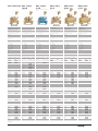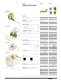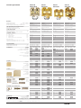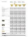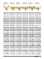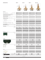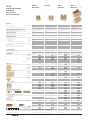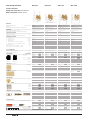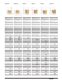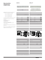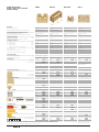
1
Pluggable cross-connection system for bestselling WDU 2.5 Cat. No. 102000 Blue, black and red cross connects available on request 40% of all terminal blocks are cross-connected. Considerable assembly time saving Touch safe protection according to VBG 4 and VDE 0106, Part 100 /3.83 without additional parts No end plates or partitions for neighbouring cross-connections up to 400 V Contact elements can be removed by hand, so that several terminals can be skipped 1/1 Feed-through terminal blocks Dimensions Width/length/height (mm) with TS 32 Y Width/length/height (mm) with TS 35 x 7.5 W Insulation stripping length/clamping screw VDE rated data. 0611 Part 1/8.92/IEC 947-7-1 Rated voltage/rated current/rated cross-section Rated impulse voltage/pollution severity Further technical data Tightening torque range Nm Torque setting with DMS2 electric screwdriver Clampable conductor “e” solid H07V-U mm2 “m” stranded H07V-R mm2 “f” flexible H07V-K mm2 “f” flexible H07V-K and AEH DIN 46 228/1 mm2 “f” flexible H07V-K and AEH + plastic insul. collar mm2 Gauge pin to 947-1 size Continuous current rating of cross-connection size 2–5 polesA Continuous current rating of cross-connection size 6–10 polesA UL/CSA rated data Voltage/current/conductor size UL Voltage/current/conductor size CSA Ordering data Version Wemid blue Wemid orange PA 10 Terminal blocks marked 1–9 Wemid 10 Terminal blocks unmarked* Wemid Wemid blue Wemid End plate/partition WAP(thickness 1.5 mm) Wemid blue Wemid WTW Wemid blue Wemid Cross-connection 2 poles WQV WQB B/24 screen lug LS 2.8 3 poles 4 poles 10 poles 32 poles 50 poles Notching tool WAW 1 for WQV Test adapter WTA TA 1 Strain relief Test plug/socket PS 2.3 Cover WAD with Symbol WAD white for self-labelling Group marking T5 StB 8.5 WDU 2.5N WDU 2.5N/10 WDU 1.5/ZZ WDU 2.5/1.5/ZR WDU 2.5 WDU 2.5/10 – 5/44/37.5 10 mm/M 2.5/3.5 x 0.6 – 5/60/47 7 mm/M 2.5/3.5 x 0.6 – 5/60/47 10/7 mm/M 2.5/3.5 x 0.6 – 5/60/47 10 mm/M 2.5/3.5 x 0.6 500 V/24 A/2.5 mm2 6 kV/3 500 V/17.5 A/1.5 mm2 8 kV/3 500 V/24/17.5 A/2.5/1.5 mm2** 8 kV/3 800 V/24 A/2.5 mm2 8 kV/3 0.4...0.7 1 0.4...0.7 1 0.4...0.7 1 0.4...0.8 1 0.5…4 1.5…4 0.5…4 0.5…2.5 0.5…2.5 A3 26 26 0.5…2.5 1.5…2.5 0.5…1.5 0.5…1.5 0.5…1.5 A1 35 35 0.5…4/2.5** 1.5…4/2.5** 0.5…4/1.5** 0.5…2.5/1.5** 0.5…2.5/1.5** A 3/A 1** 35 35 0.5…4 1.5…4 0.5…4 0.5…2.5 0.5…2.5 A3 35 35 300 V/30 A/22…12 AWG 300 V/20 A/26…12 AWG W Cat.No. For WQV 102370 For WQV 102378 For WQV 102376 For WQV 102490 For WQV 102480 For ZQV 104080 For ZQV 104088 Type Cat.No. WAP-WDU 2.5N 106000 WAP-WDU 2.5N 106008 TW (1.5) 019186 300 V/25 A/22…14 AWG 300 V/10 A/26…14 AWG W Cat.No. Qty. 103140 100 103148 100 300 V/20/15 A/22…12 AWG 300 V/20/15 A/26…12/14 AWG W Cat.No. Qty. 102470 100 102478 100 600 V/25 A/22…12 AWG 600 V/20 A/26…12 AWG W Cat.No. Qty. 102000 100 102008 100 102006 100 102070 10 102080 10 Type WAP 2.5-10 WAP 2.5-10 WTW 2.5-10 WTW 2.5-10 Cat.No. 105000 105008 105010 105018 Qty. 50 50 20 20 Type WAP 2.5-10 WAP 2.5-10 WTW 2.5-10 WTW 2.5-10 Cat.No. 105000 105008 105010 105018 Qty. 50 50 20 20 105366 105376 105386 105446 157760 50 50 50 20 10 WQV WQV WQV WQV WQV 105366 105376 105386 105446 157760 50 50 50 20 10 Type WAP 2.5-10 WAP 2.5-10 WTW 2.5-10 WTW 2.5-10 ZQV 2.5N 169380 60 169381 60 169382 60 169388 20 Cat.No. Qty. 105000 50 105008 50 105010 20 105018 20 WQV 2.5 105366 50 105376 50 105386 50 105446 20 ZQV 2.5N 169380 169381 169382 169388 Qty. 100 100 100 10 10 100 100 Qty. 50 50 20 WQV 2.5 105366 105376 105386 105446 157760 50 50 50 20 10 WQV WQV WQV WQV WQV 169389 5 WQB B/24 157906 20 WAW 1 900450 – WQB B/24 LS 2.8 WAW 1 157906 105640 900450 20 50 – WQB B/24 LS 2.8 WAW 1 157906 105640 900450 20 50 – 169389 5 WQB B/24 LS 2.8 WAW 1 157906 105640 900450 20 50 – WTA 1 WTA 1/ZA WTA 1/10 ZE 1 163229 163230 163231 163215 50 50 5 50 WTA 2 WTA 2/ZA WTA 2/10 ZE 1 163232 163233 163234 163215 50 50 5 50 WTA 2 WTA 2/ZA WTA 2/10 ZE 1 163232 163233 163234 163215 50 50 5 50 WTA 2 WTA 2/ZA WTA 2/10 ZE 1 163232 163233 163234 163215 50 50 5 50 PS 2.3 (ø 2.3) PS 2.0 (ø 2.0) StB 8.5 (ø 2.3) StB 8.5 (ø 2.0) 018040 029380 021570 126980 20 20 50 50 PS 2.3 (ø 2.3) PS 2.0 (ø 2.0) StB 8.5 (ø 2.3) StB 8.5 (ø 2.0) 018040 029380 021570 126980 20 20 50 50 PS 2.3 (ø 2.3) PS 2.0 (ø 2.0) StB 8.5 (ø 2.3) StB 8.5 (ø 2.0) 018040 029380 021570 126980 20 20 50 50 PS 2.3 (ø 2.3) PS 2.0 (ø 2.0) StB 8.5 (ø 2.3) StB 8.5 (ø 2.0) 018040 029380 021570 126980 20 20 50 50 WAD 4 107200 50 WAD 5 105346 50 WAD 4 white 107210 50 WAD 5 white 105606 50 WGB 5 105076 50 60 60 60 20 2.5/2 2.5/3 2.5/4 2.5/10 2.5/32 WGB Tag carrier for S 10-markers Marking tags T5 SF 10 SG 10 034850 100 033240 1000 033250 1000 T5 SF 10 SG 10 034850 100 033240 1000 033250 1000 Print Consecutive horizontal FW 5 047346 – FW 5 047346 1 2 3 4 5 6 Consecutive vertical FS 5 047356 – FS 5 047356 Mounting rails, brackets, additional marking material and accessories please see relevant Catalogue Section * with unprinted ”dekafix” marking strips 1/2 2.5/2 2.5/3 2.5/4 2.5/10 2.5/32 – – T5 SF 10 SG 10 034850 100 033240 100 033250 1000 T5 SF 10 SG 10 034850 100 033240 1000 033250 1000 FW 5 FS 5 047346 047356 FW 5 FS 5 047346 047356 ** Twin connection 1 – – ) PA66 – – WDK 2.5 WDK 2.5/10 WDK 2.5 WDK 2.5 V WDK 2.5 DU-PE WDK 2.5 E WDK 2.5 EGET.SCH. 800 V Terminal blocks for electrical components 400 V Modular terminals with electronic components, see from page 1/112 – – 5/69/63 10 mm/M 2.5/3.5 x 0.6 – 6/69/63 10 mm/M 2.5/3.5 x 0.6 – 5/69/63 10 mm/M 2.5/3.5 x 0.6 – 5/69/63 10 mm/M 2.5/3.5 x 0.6 400 V/24 A/2.5 mm2 6 kV/3 800 V/24 A/2.5 mm2 8 kV/3 400 V/24 A/2.5 mm2 6 kV/3 400 V/-/24 A/-/2.5 mm2 6 kV/3 -/-/2.5 mm2 -/- 0.4...0.7 1 0.4...0.7 1 0.4...0.7 1 0.4...0.7 1 0.4...0.7 1 0.5…4 1.5…4 0.5…2.5 0.5…2.5 0.5…2.5 A3 35 35 0.5…4 1.5…4 0.5…2.5 0.5…2.5 0.5…2.5 A3 35 35 0.5…4 1.5…4 0.5…2.5 0.5…2.5 0.5…2.5 A3 35 35 0.5…4 1.5…4 0.5…2.5 0.5…2.5 0.5…2.5 A3 35/35/- 0.5…4 1.5…4 0.5…2.5 0.5…2.5 0.5…2.5 A3 - 600 V/20 A/22…12 AWG 300 V/10 A/26…12 AWG W Cat.No. Qty. 102230 100 300 V/20 A/22…12 AWG*** 300 V/10 A/26…12 AWG*** W Cat.No. Qty. 103640 100 lower connection range marked green-yellow - RA Cat.No. Qty. 102320 100 102310* 100 209568** 100 Cat.No. 105910 105918 105880 Qty. 20 20 20 105366 105376 105386 105446 157760 50 50 50 20 10 600 V/20 A/22…12 AWG 300 V/10 A/26…12 AWG W Cat.No. Qty. 102150 100 102158 100 102156 100 102560 10 102570 10 Type WAP WAP WTW Cat.No. 105910 105918 105880 Qty. 20 20 20 WQV WQV WQV WQV WQV 105366 105376 105386 105446 157760 50 50 50 20 10 WQB A/24 LS 2.8 WAW 1 157900 105640 900450 TA 1 W Cat.No. 102910 Qty. 100 Type WAP WAP WTW Cat.No. 105910 105918 105880 Qty. 20 20 20 Q Q Q Q 2 3 4 10 036900 036910 036920 036930 50 50 50 20 20 50 – LS 2.8 105640 50 053586 20 TA 1 053586 AD 3 HP 3 048540 048576 – 20 AD 3 HP 3 048540 048576 WT 4 SF 10 SG 10 134106 100 033240 1000 033250 1000 WT 4 SF 10 SG 10 FW 5 FS 5 047346 047356 FW 5 FS 5 2.5/2 2.5/3 2.5/4 2.5/10 2.5/32 – – 5/69/63 10 mm/M 2.5/3.5 x 0.6 W Type WAP Cat.No. 105910 Qty. 20 Type WAP Cat.No. 105910 Qty. 20 WTW 105880 20 WTW 105880 20 Type WAP WAP WTW 105366 105376 105386 105446 157760 50 50 50 20 10 WQV WQV WQV WQV WQV 105366 105376 105386 105446 157760 50 50 50 20 10 WQV WQV WQV WQV WQV WQB A/24 LS 2.8 WAW 1 157900 105640 900450 20 50 – WQB A/24 157900 20 WAW 1 900450 – WQB A/24 LS 2.8 WAW 1 157900 105640 900450 20 50 – 20 TA 1 053586 20 TA 1 053586 20 TA 1 053586 20 – 20 AD 3 HP 3 048540 048576 – 20 AD 3 HP 3 048540 048576 – 20 AD 3 HP 3 048540 048576 – 20 134106 100 033240 1000 033250 1000 WT 4 SF 10 SG 10 134106 100 033240 1000 033250 1000 WT 4 SF 10 SG 10 134106 100 033240 1000 033250 1000 WT 4 SF 10 SG 10 134106 100 033240 1000 033250 1000 047346 047356 FW 5 FS 5 047346 047356 FW 5 FS 5 047346 047356 FW 5 FS 5 047346 047356 * split current bar – – WQV WQV WQV WQV WQV 2.5/2 2.5/3 2.5/4 2.5/10 2.5/32 ** matching contour frame – – 2.5/2 2.5/3 2.5/4 2.5/10 2.5/32 – – 2.5/2 2.5/3 2.5/4 2.5/10 2.5/32 – – *** is applied for 1/3 Feed-through terminal blocks Dimensions Width/length/height (mm) with TS 32 Y Width/length/height (mm) with TS 35 x 7.5 W Insulation stripping length/clamping screw VDE rated data. 0611 Part 1/8.92/IEC 947-7-1 Rated voltage/rated current/rated cross-section Rated impulse voltage/pollution severity Further technical data Tightening torque range Torque setting with DMS2 electric screwdriver Clampable conductor “e” solid H07V-U “m” stranded H07V-R “f” flexible H07V-K “f” flexible H07V-K and AEH DIN 46 228/1 “f” flexible H07V-K and AEH with plastic ins. collar Gauge pin to 947-1 Cont. current rating of cross-connection 2-poles Cont. current rating of cross-connection size multipole Nm mm2 mm2 mm2 mm2 mm2 size A A UL/CSA rated data Voltage/current/conductor size Voltage/current/conductor size Ordering data UL CSA Version Wemid blue Wemid 10 Terminal blocks marked 1–9 Wemid 10 Terminal blocks unmarked* Wemid Motor connection block (L1. L2. L3. PE) Wemid Motor connection block (L1. L2. L3. N. PE) Wemid End plate/partition WAP (thickness 1.5 mm) Wemid blue Wemid WTW Wemid blue Wemid Cross-connection WQV screen lug LS 2.8 Notching tool WAW 1 for WQV Test adapter WTA 5 WTA 3 (Strain relief.) Test plug/socket PS 2.3 Cover WAD with Symbol WAD white for self-labelling Group marking T5 Tag carrier for S 10 markers Marking tabs StB 8.5 WGB WDU 4 WDU 4/10 WMA 4/5 WMA 4/4 WDU 6 WDU 6/10 WDU 10 – 6/60/47 10 mm/M 3/3.5 x 0.6 – 60/60/47 10 mm/M 3/3.5 x 0.6 – 8/60/47 12 mm/M 3.5/4.0 x 0.8 – 10/60/47 12 mm/M 4/5.5 x 1.0 800 V/32 A/4 mm2 8 kV/3 1000 V/32 A/4 mm2 8 kV/3 800 V/41 A/6 mm2 8 kV/3 1000 V/57 A/10 mm2 8 kV/3 0.5...1.0 2 0.5...1.0 2 0.8...1.6 3 1.2...2.4 4 0.5…6 1.5…6 0.5…6 0.5…4 0.5…4 A4 46 46 0.5…6 1.5…6 0.5…6 0.5…4 0.5…4 A4 46 46 0.5…10 1.5…10 0.5…10 0.5…6 0.5…6 A5 63 63 1.5…16 1.5…16 1.5…16 1.5…16 1.5…16 B6 85 63 600 V/35 A/22…10 AWG 600 V/35 A/26…10 AWG W Cat.No. Qty. 102010 100 102018 100 102090 10 102100 10 600 V/35 A/22…10 AWG 600 V/35 A/26…10 AWG W Cat.No. Qty. 600 V/45 A/20…8 AWG 600 V/45 A/20…8 AWG W Cat.No. Qty. 102020 50 102028 50 102140 10 102130 10 600 V/65 A/16…6 AWG 600 V/65 A/16…6 AWG W Cat.No. Qty. 102030 50 102038 50 Type WAP 2.5-10 WAP 2.5-10 WTW 2.5-10 WTW 2.5-10 Cat.No. 105000 105008 105010 105018 Qty. 50 50 20 20 Type WAP 2.5-10 WAP 2.5-10 WTW 2.5-10 WTW 2.5-10 Cat.No. 105000 105008 105010 105018 Qty. 50 50 20 20 105236 105476 105486 105226 50 50 50 20 WQV WQV WQV WQV 105256 105496 105506 105246 50 50 50 20 Type WAP 2.5-10 WAP 2.5-10 WTW 2.5-10 WTW 2.5-10 103400 103380 Cat.No. 105000 105008 105010 105018 20 20 Qty. 50 50 20 20 105196 105456 105466 105206 50 50 50 20 WQV WQV WQV WQV LS 2.8 WAW 1 105640 900450 50 – LS 2.8 WAW 1 105640 900450 50 – Type WAP 2.5-10 WAP 2.5-10 WTW 2.5-10 WTW 2.5-10 Cat.No. 105000 105008 105010 105018 Qty. 50 50 20 20 WQV WQV WQV WQV 105196 105456 105466 105206 50 50 50 20 WQV WQV WQV WQV LS 2.8 WAW 1 105640 900450 50 – LS 2.8 WAW 1 105640 900450 50 – WTA 3 163235 50 WTA 3 163235 50 WTA 3/ZA WTA 3/10 ZE 1 163236 163237 163215 50 5 50 WTA 3/ZA WTA 3/10 ZE 1 163236 163237 163215 50 5 50 WTA 5/1 105126 25 WTA 5/1 105126 25 PS 2.3 (ø 2.3) 018040 20 PS 2.3 (ø 2.3) 018040 20 StB 8.5 (ø 2.3) 028060 50 StB 8.5 (ø 2.3) 028060 50 PS 2.3 (ø 2.3) PS 4 (ø 4) StB 8.5 (ø 2.3) StB 14 (ø 4) 018040 029960 028060 016990 20 20 50 50 PS 2.3 (ø 2.3) PS 4 (ø 4) StB 8.5 (ø 2.3) StB 14 (ø 4) 018040 029960 028060 016990 20 20 50 50 WAD 5 WAD 5 white 105346 105606 50 50 WAD 5 WAD 5 white 105346 105606 50 50 WAD 8 WAD 8 white 105356 105616 50 50 WAD 8 WAD 8 white 105356 105616 50 50 WGB 5 105076 50 WGB 5 105076 50 WGB 8 105096 50 WGB 8 105096 50 T5 SF 10 SG 10 034850 100 033240 1000 033250 1000 T5 SF 10 SG 10 034850 100 033240 1000 033250 1000 T5 SF 10 SG 10 034850 100 033240 1000 033250 1000 T5 SF 10 SG 10 034850 100 033240 1000 033250 1000 FW 8 FS 8 127696 128966 FW 5 FS 5 047346 047356 4/2 4/3 4/4 4/10 4/2 4/3 4/4 4/10 Print Consecutive horizontal FW 6 046866 – FW 6 046866 1 2 3 4 5 6 Consecutive vertical FS 6 047356 – FS 6 047356 Mounting rails, brackets, additional marking material and accessories please see relevant Catalogue Section * With unprinted“dekafix” marking stripes 1/4 – – 6/2 6/3 6/4 6/10 – – 10/2 10/3 10/4 10/10 – – WDU 16N WDU 16 WDU 16/ZA* WDU 35 WDU 35/ZA* WDU 70N – 12/60/47 12 mm/M 4/5.5 x 1.0 – 12/60/63 16 mm/M 5/5.5 x 1.0 – 12/60/63 16 mm/M 5/5.5 x 1.0 – 16/60/63 18 mm/M 6/5.5 x 1.0 – 16/60/63 18 mm/M 6/5.5 x 1.0 20.5/75/93.5 20.5/75/86 22 mm/M 8/S 6 DIN 6911 400 V/76 A/16 mm2 6 kV/3 1000 V/76 A/16 mm2 8 kV/3 1000 V/76 A/16 mm2 8 kV/3 1000 V/125 A/35 mm2 8 kV/3 1000 V/125 A/35 mm2 8 kV/3 1000 V/192 A/70 mm2 8 kV/3 1.2...2.4 4 2.0...4.0 – 2.0...4.0 – 2.5...5.0 – 2.5...5.0 – 6.0...12 – 1.5…16 1.5…25 1.5…16 1.5…16 1.5…16 B7 76 57 (3 + 4 poles) 1.5…16 1.5…25 1.5…25 1.5…16 1.5…16 B7 85 63 1.5…16 1.5…25 1.5…25 1.5…16 1.5…16 B7 85 63 2.5...16 2.5…50 2.5…35 2.5…35 2.5…35 B9 138 112 2.5...16 2.5…50 2.5…35 2.5…35 2.5…35 B9 168 A/50 mm2 138 112 10...16 10...95 10...70 10...70 10...70 B 11 207 A/95 mm2 192 192 (3pole) - 600 V/70 A/14…6 AWG 600 V/65 A/14…6 AWG W Cat.No. Qty. 102040 50 102048 50 600 V/70 A/14…6 AWG 600 V/65 A/14…6 AWG W Cat.No. Qty. 102890 50 102898 50 600 V/115 A/12…2 AWG 600 V/120 A/12…2 AWG W Cat.No. Qty. 102050 25 102058 25 (hexagon socket)102060 25 (hexagon socket)102068 25 600 V/115 A/12…2 AWG 600 V/120 A/12…2 AWG W Cat.No. Qty. 102880 25 102888 25 (hexagon socket)102900 25 (hexagon socket)102908 25 600 V/175 A/6...2/0 AWG 600 V/205 A/8...2/0 AWG W Cat.No. Y Cat.No. Qty. 951219 951222 10 951242 951243 10 W Cat.No. 103610 103618 Qty. 50 50 (WDU 70N only with hex.socket) Type Cat.No. Qty. WTW EX 105880 20 WQV 16N/2 WQV 16N/3 WQV 16N/4 163656 163657 163658 50 50 50 WAW 1 900450 – Type WAP 16–35 WAP 16–35 Cat.No. 105010 105018 Qty. 20 20 WQV WQV WQV WQV WQV 105326 105516 105526 105336 105328 50 50 50 10 50 900450 – 16/2 16/3 16/4 16/10 16/2 blue WAW 1 Type WAP 16–35 WAP 16–35 Cat.No. 105010 105018 Qty. 20 20 WQV WQV WQV WQV WQV 105236 105516 105526 105336 105328 50 50 50 10 50 900450 – 16/2 16/3 16/4 16/10 16/2 blue WAW 1 Type WAP 16–35 WAP 16–35 Cat.No. 105010 105018 Qty. 20 20 WQV WQV WQV WQV WQV 105306 105536 105546 105316 105308 50 50 50 10 50 900450 – 35/2 35/3 35/4 35/10 35/2 blue WAW 1 Type WAP 16–35 WAP 16–35 Cat.No. 105010 105018 Qty. 20 20 WQV WQV WQV WQV WQV 105306 105536 105546 105316 105308 50 50 50 10 50 900450 – 35/2 35/3 35/4 35/10 35/2 blue WAW 1 Type WQV 70N/2 WQV 70N/3 Cat.No. Qty. 951224 951225 5 5 Auxil./control conduc. term WZAD 70N PS 2.3 (ø 2.3) PS 4 (ø 4) StB 8.5 (ø 2.3) StB 14 (ø 4) 018040 029960 028060 016990 20 20 50 50 951228 10 PS 4 (ø 4) 029960 20 PS 4 (ø 4) 029960 20 PS 4 (ø 4) 029960 20 PS 4 (ø 4) 029960 20 StB 16 (ø 4) 014020 50 StB 16 (ø 4) 014020 50 StB 16 (ø 4) 014020 50 StB 16 (ø 4) 014020 50 PS 4 (ø 4) 029960 20 insertable in screw head of connection system WAD 12 105596 WAD 12 white 105626 50 50 WAD 12 105596 WAD 12 white 105626 50 50 WAD 12 105596 WAD 12 white 105626 50 50 WAD 12 105596 WAD 12 white 105626 50 50 WAD 20 951226 WAD 20 white 951227 20 20 T5 SF 10 SG 10 034850 100 033240 1000 033250 1000 T5 SF 10 SG 10 034850 100 033240 1000 033250 1000 T5 SF 10 SG 10 034850 100 033240 1000 033250 1000 T5 SF 10 SG 10 034850 100 033240 1000 033250 1000 T5 SF 10 SG 10 034850 100 033240 1000 033250 1000 T5 SF 10 SG 10 034850 100 033240 1000 033250 1000 FW 5 FS 5 047346 047356 FW 5 FS 5 047346 047356 FW 5 FS 5 047346 047356 FW 5 FS 5 047346 047356 FW 5 FS 5 047346 047356 FW 5 FS 5 047346 047356 – – – – * With spigots – – – – – – – – 1/5 Feed-through terminal blocks Large size conductors no longer have to be inserted into the clamping point with force; they can simply be placed in the terminal block. For each terminal type, terminal block variants consisting of three, four and fivepole terminal blocks are available in addition to the individual terminals. All blocks are permanently screwed together for additional rigidity. Slots provided in the underside of the terminal enable direct fitting. Terminal blocks can be screwed directly to mounting plates with 25 mm pitch. Further advantages are: • Constant force transmission by selfadjusting connection resistance • Random wiring direction • Safe from finger-touch (VGB 4), even with cross-connection fitted • Good distortion resistance WDU 70/95 Dimensions Width/length/height (mm) with TS 32 Y Width/length/height (mm) with TS 35 x 7.5 W Insul. stripping length/clamping screw/setting acc. DIN 6911 VDE rated data. 0611 Part 1/8.92/IEC 947-7-1 Rated voltage/rated current/rated cross-section Rated impulse voltage/pollution severity Further technical data Tightening torque range Nm Torque setting with DMS2 electric screwdriver Clampable conductor “e” solid H07V-U mm2 “m” stranded H07V-R mm2 “f” flexible H07V-K mm2 “f” flexible H07V-K and AEH DIN 46 228/1 mm2 “f” flexible H07V-K and AEH with Plastic.Col. mm2 Gauge pin to 947-1 size Cont. current rating of cross-connection 2 poles A Cont. current rating of cross-connection multipole A UL/CSA rated data Voltage/current/conductor size Voltage/current/conductor size Ordering data hexagon socket 6 mm hexagon socket 6 mm hexagon socket 6 mm hexagon socket 6 mm hexagon socket 6 mm hexagon socket 6 mm Mains terminal block 3x Cross-connection UL CSA Version Wemid blue Wemid green Wemid Terminal block* 3 poles Wemid Terminal block* 4 poles Wemid Terminal block* 5 poles Wemid beige. 1x blue. 1x green Wemid – 27/132/108 30 mm/M 8/S 6 27/132/117 – 30 mm/M 8/S 6 1000 V/232 A/95 mm2 8 kV/3 1000 V/232 A/95 mm2 8 kV/3 6...12 – 6...12 – 16 16…120 16…95 – – B 12 207 (3) 207 16 16…120 16…95 – – B 12 207 (3) 207 600 V/175 A/6…2/0 AWG 600 V/205 A/6…2/0 AWG W Cat.No. Qty. 102460 10 102468 10 102465 10 600 V/175 A/6…2/0 AWG 600 V/205 A/6…2/0 AWG Y Cat.No. 103150 103158 103155 Qty. 10 10 10 Type WQV 70/2 WQV 70/3 Cat.No. 106350 106360 Qty. 5 5 Type WQV 70/2 WQV 70/3 Cat.No. 106350 106360 Qty. 5 5 WZAD 70 106600 10 WZAD 70 106600 10 WAD 27 with warning tag 106286 10 WAD 27 with warning tag 106286 10 WAD 27 no warning tag 106296 10 WAD 27 no warning tag 106296 10 Auxiliary/control conductor terminal Open terminal cover, remove screw terminal unit Cover yellow white Test plug PS 4 029960 20 Insertable in screw head of connection system Place conductor in terminal, replace screw terminal unit PS 4 029960 Insertable in screw head of connection system 20 Fixing screw for direct assembly M 6x16 106370 20 hex. key 040790 6 mm to DIN 6911 – SD 903709 – 047346 047356 – – Hexagon key hex. key 040790 6 mm to DIN 6911 – FW 5 FS 5 – – Screwdriver for direct assembly 1 x 5.5 x 125 Marking tabs Close terminal cover, tighten screw with hex key 1/6 Print Consecutive horizontal FW 5 1 2 3 4 5 6 Consecutive vertical FS 5 Mounting rails, brackets, additional marking material and accessories 047346 047356 WDU 70/95/… WDU 120/150 WDU 120/150/… Template for direct mounting Template for direct mounting – 81/132/108 (triple block)* 30 mm/M 8/S 6 – 32/132/118 35 mm/M 10/S 6 32/132/127 – 35 mm/M 10/S 6 – 96/132/118 (triple block)* 35 mm/M 10/S 6 1000 V/192 A/70 mm2 8 kV/3 1000 V/269 A/120 mm2 8 kV/3 1000 V/269 A/120 mm2 8 kV/3 1000 V/269 A/120 mm2 8 kV/3 6...12 – 10...20 – 10...20 – 10...20 – 16 16…120 16…95 – – B 12 207 (3) 207 – 35…150 35…150 – – B 13 292 (3) 292 – 35…150 35…150 – – B 13 292 (3) 292 – 35…150 35…150 – – B 13 292 (3) 292 600 V/175 A/6…2/0 AWG 600 V/205 A/6…2/0 AWG W Cat.No.. Qty. 600 V/225 A/2…MCM 250 AWG 600 V/285 A/2…MCM250 AWG W Cat.No. Qty. 102450 10 102458 10 102455 10 600 V/225 A/2…MCM 250 AWG 600 V/285 A/2…MCM 250 AWG Y Cat.No. Qty. 103160 10 103168 10 103165 10 Type WQV 70/2 WQV 70/3 102670* 4 102680* 3 102690* 2 103230* 2 Cat.No. Qty. 106350 5 106360 5 600 V/225 A/2…MCM 250 AWG 600 V/285 A/2…MCM 250 AWG Cat.No. Qty. 102640* 3 102650* 2 102660* 2 103240* 2 Type WQV 120/2 WQV 120/3 Cat.No. 106330 106340 Qty. 5 5 Type WQV 120/2 WQV 120/3 Cat.No. 106330 106340 Qty. 5 5 Type WQV 120/2 WQV 120/3 Cat.No. 106330 106340 Qty. 5 5 WZAD 70 106600 10 WZAD 120 106610 10 WZAD 120 106610 10 WZAD 120 106610 10 WAD 27 w. warning tag 106286 10 WAD 27 w. warning tag 106286 10 WAD 27 w. warning tag 106286 10 WAD 27 w. warning tag 106286 10 WAD 27 no warning tag 106296 10 WAD 27 no warning tag 106296 10 WAD 27 no warning tag 106296 10 WAD 27 no warning tag 106296 10 PS 4 029960 20 Insertable in screw head of connection system PS 4 029960 20 Insertable in screw head of connection system M 6x16 M 6x16 106370 20 106370 PS 4 029960 20 Insertable in screw head of connection system PS 4 029960 20 Insertable in screw head of connection system 20 M 6x16 Hex. key 040790 6 mm acc DIN 6911 – Hex. key 040790 6 mm acc DIN 6911 – SD 903709 – SD 903709 – FW 5 FS 5 047346 047356 – – FW 5 FS 5 047346 047356 – – Hex. key 040790 6 mm acc DIN 6911 FW 5 FS 5 047346 047356 – – – 106370 20 Hex. key 040790 6 mm acc DIN 6911 – SD 903709 – FW 5 FS 5 047346 047356 – – * Terminal block for direct assembly only 1/7 Tab connection terminals WFF 35 WFF 70 # Y Dimensions Width/length/height (mm) Width/length/height (mm) with WAH covers Bolt size VDE rated data. 0611 Part 1/8.92/IEC 947-7-1 Rated voltage/rated current/rated cross-section Rated impulse voltage/pollution severity Further technical data Tightening torque range Clampable conductor Cable lug DIN 46 235 Cable lug DIN 46 234 2 x Cable lug DIN 46 235 2 x Cable lug DIN 46 234 Strips Strips Strips Gauge for flat connections to EN 50043 Cont. current rating of Cross-connection 2 poles Cont. current rating of Cross-connection 3 poles UL/CSA rated data Voltage/current/conductor size Voltage/current/conductor size Ordering data W M Nm mm2 mm2 mm2 mm2 mm mm mm size A A UL CSA Version Wemid blue Wemid Wemid Wemid With covers Partition (thickness 2 mm) Cross-connection WQL Y Template for direct mounting Y W Template for direct mounting Y 27/107/54 27/136/60 6 27/107/62.5 27/136/68 6 32/132/63 32/179/71.5 8 32/132/71.5 32/179/80 8 1000 V/125 A/35 mm2 8 kV/3 1000 V/125 A/35 mm2 8 kV/3 1000 V/192 A/70 mm2 8 kV/3 1000 V/192 A/70 mm2 8 kV/3 3.0...6.0 3.0...6.0 6.0...12 6.0...12 6…25 2.5…50 6…25 2.5…35 3 x 13 x 0.5 6 x 13 x 0.5 2 x 15.5 x 0.8 C4 135 135 6…25 2.5…50 6…25 2.5…35 3 x 13 x 0.5 6 x 13 x 0.5 2 x 15.5 x 0.8 C4 135 135 16…70 2.5…120 16…70 2.5…70 2 x 15.5 x 0.8 4 x 15.5 x 0.8 6 x 15.5 x 0.8 C6 207 207 16…70 2.5…120 16…70 2.5…70 2 x 15.5 x 0.8 4 x 15.5 x 0.8 6 x 15.5 x 0.8 C6 207 207 600 V/115 A/14…2 AWG 600 V/130 A/14…2 AWG W Cat.No. Qty. 102830 10 102838 10 102930 10 600 V/115 A/14…2 AWG 600 V/130 A/14…2 AWG Y Cat.No. Qty. 103170 10 103178 10 600 V/175 A/14…2/0 AWG 600 V/170 A/14…2/0 AWG W Cat.No. Qty. 102840 10 102848 10 102940 10 600 V/175 A/14…2/0 AWG 600 V/170 A/14…2/0 AWG Y Cat.No. Qty. 103180 10 103188 10 Type WTW WFF 35 Cat.No. 106710 Qty. 10 Type WTW WFF 35 Cat.No. 106710 Qty. 10 Type WTW WFF 70 Cat.No. 106720 Qty. 10 Type WTW WFF 70 Cat.No. 106720 Qty. 10 WQL 2/35 WQL 3/35 106490 106540 5 5 WQL 2/35 WQL 3/35 106490 106540 5 5 WQL 2/70 WQL 3/70 106500 106550 5 5 WQL 2/70 WQL 3/70 106500 106550 5 5 WZAF 35 107050 10 WZAF 35 107050 10 WZAF 70 106620 10 WZAF 70 106620 10 WAH 35 WAH 35 BL WAH 35 HG WAP* 106446 106448 106445 106970 20 20 20 20 WAH 35 WAH 35 BL WAH 35 HG WAP* 106446 106448 106445 106970 20 20 20 20 WAH 70 WAH 70 BL WAH 70 HG WAP* 106456 106458 106455 106980 20 20 20 20 WAH 70 WAH 70 BL WAH 70 HG WAP* 106456 106458 106455 106980 20 20 20 20 4 x 20 x 1 4 x 20 x 1 auxiliary/ control conductor terminal Cover beige PA 66 blue PA 66 light green PA 66 Warning sign Yellow, Self-adhesive With lightning flash Can be stuck on WAH only WD 1 156390 5 Qty. = 5 cards with 6 labels on each WD 1 156390 5 Qty. = 5 cards with 6 labels on each WD 1 156390 5 Qty. = 5 cards with 6 labels each WD 1 156390 5 Qty. = 5 cards with 6 labels each Fixing screw For direct assembly Screwdriver M 6 x 16 SD 106370 902450 20 – CPSB M 6 015620 50 M 6 x 16 SD 106370 902450 20 – CPSB M 8 015630 50 Cupal washers For aluminium conductors CPSB M 6 015620 Print Consecutive horizontal FW 5 047346 – FW 5 047346 1 2 3 4 5 6 Consecutive vertical FS 5 047356 – FS 5 047356 Mounting rails, brackets, additional marking material and accessories please see relevant Catalogue Section 50 CPSB M 8 015630 50 FW 5 FS 5 047346 047356 – – Marking tabs – – FW 5 FS 5 047346 047356 – – * The WAP can be used only in conjunction with the WAH. In the event that no conductor is connected, it guarantees shock prevention in the connection area. 1/8 # WFF 70 and WFF 185 can accept voltages up to 2400V when tested to VDE 0115. WFF 120 WFF 185 # WFF 185 M 12 + M 16 Y W WFF 300 Y Template for direct mounting Y Y Template for direct mounting Y W Template for direct mounting Y W 42/132/72 42/230/81 10 42/132/81 42/230/89 10 55/163/78 55/287/91 12 55/163/86.5 55/287/99 12 55/163/86 55/287/90 16 55/163/94.5 55/287/99 16 1000 V/269 A/120 mm2 8 kV/3 1000 V/269 A/120 mm2 8 kV/3 1000 V/353 A/185 mm2 8 kV/3 1000 V/353 A/185 mm2 8 kV/3 1000 V/520 A/300 mm2 8 kV/3 1000 V/520 A/300 mm2 8 kV/3 10...20 10...20 14...31 14...31 25...60 25...60 16…150 6…150 16…120 6…120 2 x 20 x 1 6 x 20 x 1 5 x 24 x 1 C8 292 292 16…150 6…150 16…120 6…120 2 x 20 x 1 6 x 20 x 1 5 x 24 x 1 C8 292 292 25…240 10…240 25…185 10…185 2 x 24 x 1 2 x 32 x 1 3 x 35 x 1 C 11 382 382 25…240 10…240 25…185 10…185 2 x 24 x 1 2 x 32 x 1 3 x 35 x 1 C 11 382 382 50…300 25…240 50…240 25…240 2 x 40 x 1 6 x 40 x 1 8 x 40 x 1 – 520 520 50…300 25…240 50…240 25…240 2 x 40 x 1 6 x 40 x 1 8 x 40 x 1 520 520 600 V/310 A/10…MCM 250 AWG 600 V/310 A/10…MCM 250 AWG W Cat.No. Qty. 102850 5 102858 5 102950 5 600 V/310 A/10…MCM 250 AWG 600 V/310 A/10…MCM 250 AWG Y Cat.No. Qty. 103190 5 103198 5 600 V/380 A/8…MCM 500 AWG 600 V/360 A/8…MCM 500 AWG W Cat.No. Qty. 102860 4 102868 4 102960 4 (M12+M16) 102865 4 600 V/380 A/8…MCM 500 AWG 600 V/360 A/8…MCM 500 AWG Y Cat.No. Qty. 103200 4 103208 4 600 V/500 A/6…MCM 600 AWG 600 V/510 A/6…MCM 600 AWG W Cat.No. Qty. 102870 4 102878 4 102970 4 600 V/500 A/6…MCM 600 AWG 600 V/510 A/6…MCM 600 AWG Y Cat.No. Qty. 103210 4 103218 4 Type Cat.No. WTW WFF 120 106730 Type Cat.No. WTW WFF 120 106730 Type Cat.No. WTW WFF 185 106740 Type Cat.No. WTW WFF 185 106740 Type Cat.No. WTW WFF 300 106740 Type Cat.No. WTW WFF 300 106740 Qty. 10 Qty. 10 WQL 2/120 WQL 3/120 106510 106560 5 5 WQL 2/120 WQL 3/120 106510 106560 5 5 WZAF 120 106630 10 WZAF 120 106630 WAH 120 WAH 120 BL WAH 120 HG WAP* 106466 106468 106465 107300 20 20 20 20 WAH 120 WAH 120 BL WAH 120 HG WAP* 106466 106468 106465 106980 WD 1 156390 5 Qty. = 5 cards with 6 labels each M 6 x 16 SD 106370 902450 20 – CPSB M 10 015640 50 FW 5 FS 5 047346 047356 – – 10 x 24 x 1 6 x 32 x 1 Qty. 10 10 x 24 x 1 6 x 32 x 1 Qty. 10 3 x 35 x 1 8 x 32 x 1 Qty. 10 3 x 35 x 1 8 x 32 x 1 Qty. 10 WQL 2 WQL 3 106520 106570 50 50 WQL 2 WQL 3 106520 106570 50 50 WQL 2 WQL 3 106530 106580 50 50 WQL 2 WQL 3 106530 106580 50 50 10 WZAF 185 106640 10 WZAF 185 106640 10 WZAF 300 106650 10 WZAF 300 106650 10 20 20 20 20 WAH 185/300 106476 10 WAH 185/300 BL 106478 10 WAH 185/300 HG 106475 10 WAH 185/300 106476 10 WAH 185/300 BL 106478 10 WAH 185/300 HG106475 10 WAH 185/300 106476 10 WAH 185/300 BL 106478 10 WAH 185/300 HG106475 10 WAH 185/300 106476 10 WAH 185/300 BL 106478 10 WAH 185/300 HG106475 10 WD 1 156390 5 Qty. = 5 cards with 6 labels each WD 1 156390 5 Qty. = 5 cards with 6 labels each WD 1 156390 5 Qty. = 5 cards with 6 labels each WD 1 156390 5 Qty. = 5 cards with 6 labels each WD 1 156390 5 Qty. = 5 cards with 6 labels each CPSB M 10 015640 50 FW 5 FS 5 047346 047356 – – M 6 x 16 SD 106370 902450 20 – CPSB M 12 015650 20 FW 5 FS 5 047346 047356 – – # WFF 70 and WFF 185 can accept voltages up to 2400V when tested to VDE 0115. CPSB M 12 015650 20 FW 5 FS 5 047346 047356 – – M 6 x 16 SD 106370 902450 20 – CPSB M 16 015650 20 FW 5 FS 5 046866 046876 – – CPSB M 16 015650 20 FW 5 FS 5 046866 046876 – 1/9 Coloured terminals Dimensions Width/length/height (mm) With TS 32 Y Width/length/height (mm) With TS 35 x 7.5 W Insulation stripping length/clamping screw VDE rated data 0611 Part 1/8.92/IEC 947-7-1 Rated voltage/rated current/rated cross-section Rated voltage/pollution severity Further technical data (see product pages) UL/CSA rated data Voltage/current/conductor size Voltage/current/conductor size Ordering data ● ● ● ● ● ● ❍ ● ● ● ● End plate/partition WAP (thickness 1.5 mm) UL CSA Version Wemid blue Wemid yellow Wemid green Wemid brown Wemid grey Wemid white Wemid orange PA red PA violet PA black PA ● Wemid ● blue Wemid ● yellow Wemid ● green Wemid ● brown Wemid ● grey Wemid ❍ white Wemid ● orange PA ● red PA ● violet PA ● black PA ● Wemid ● blue Wemid WTW Cross-connection WQV WQB 8/24 Screen lug LS 2.8 Notching tools: WAW 1 for WQV WAW 2 to notch the punch-out in the terminal moulding Test adaptor WTA TA 1 Strain relief Test plug/socket PS 2.3 StB 8.5 Screwdriver SDIK for StB Cat.No.: 902493 Cover WAD With Symbol WAD white. for self-labelling Group marking T5 Tag carrier for S 10 markers Marking tags 1 2 3 4 5 6 WGB Print Consecutive horizontal Consecutive vertical WDU 2.5 WDU 4 WTR 2.5 WSI 6 5/60/47 10 mm/M 2.5/3.5 x 0.6 6/60/47 10 mm/M 3 /4.0 x 0.8 5/60/49 10 mm/M 2.5/3*/3.5 x 0.6 8/60/60 12 mm/M 3.5/4.0 x 0.8 1000 V/24 A/2.5 mm2 8 kV/3 1000 V/32 A /4 mm2 8 kV/3 800 V/16 A**/1.5 mm2 6 kV/3 500 V~/6.3 A**/6 mm2 6 kV/3 600 V/25 A/22…12 AWG 600 V/20 A/26…12 AWG W 102000 102008 102002 102009 103771 103772 103680 102006 102004 103770 102001 Type Cat.No. WAP 2.5-10 105000 WAP 2.5-10 105008 WAP 2.5-10 105002 WAP 2.5-10 107220 WAP 2.5-10 105007 WAP 2.5-10 105005 WAP 2.5-10 105009 WAP 2.5-10 105006 WAP 2.5-10 105004 WAP 2.5-10 107221 WAP 2.5-10 105001 WTW 2.5-10 105010 WTW 2.5-10 105018 600 V/35 A/22…10 AWG 600 V/35 A/26…10 AWG W 102010 102018 102012 102016 103781 103780 103670 103676 102014 103782 102011 Type Cat.No. WAP 2.5-10 105000 WAP 2.5-10 105008 WAP 2.5-10 105002 WAP 2.5-10 107220 WAP 2.5-10 105007 WAP 2.5-10 105005 WAP 2.5-10 105009 WAP 2.5-10 105006 WAP 2.5-10 105004 WAP 2.5-10 107221 WAP 2.5-10 105001 WTW 2.5-10 105010 WTW 2.5-10 105018 300 V/10 A/22…12 AWG 300 V/10 A/26…12 AWG Qty. 100 100 100 100 100 100 100 100 100 100 100 Qty. 50 50 50 50 50 50 50 50 50 50 50 20 20 WQV 2.5/2 WQV 2.5/3 WQV 2.5/4 WQV 2.5/10 WQB B/24 LS 2.8 WAW 1 105366 105376 105386 105446 157906 105640 900450 50 50 50 20 20 50 – WQV WQV WQV WQV WTA 2 WTA 2/ZA WTA 2/10 ZE 1 163232 163233 163234 163215 PS 2.3 (ø 2.3) PS 2.0 (ø 2.0) StB 8.5 (ø 2.3) StB 8.5 (ø 2.0) 101110 101118 101112 101113 101117 101115 101119 101116 101114 101940 101111 Type WAP 2.5-10 WAP 2.5-10 WAP 2.5-10 WAP 2.5-10 WAP 2.5-10 WAP 2.5-10 WAP 2.5-10 WAP 2.5-10 WAP 2.5-10 WAP 2.5-10 WAP 2.5-10 WTW 2.5-10 WTW 2.5-10 101120 101128 101122 101123 101127 101125 101129 101126 101124 101950 101121 Cat.No. 105000 105008 105002 107220 105007 105005 105009 105006 105004 107221 105001 105010 105018 Qty. 100 100 100 100 100 100 100 100 100 100 100 Qty. 50 50 50 50 50 50 50 50 50 50 50 20 20 QL 2 QL 3 QL 4 QL 10 BS-M 2.5 x 4.5 021580 021590 021600 033800 106270 100 100 50 20 100 QL 2 QL 3 QL 4 QL 10 BS-M 3 x 5 019430 019440 019450 033830 105210 50 50 50 20 100 WAW 2 900451 – WAW 2 900451 – Without StB 105196 105456 105466 105206 50 50 50 20 LS 2.8 WAW 1 105640 900450 50 – 50 50 5 50 WTA 3 WTA 3/ZA WTA 3/10 ZE 1 163235 163236 163237 163215 50 50 5 50 018040 029380 021570 126980 20 20 50 50 PS 2.3 (ø 2.3) 018040 20 StB 8.5 (ø 2.3) 028060 50 WAD 5 WAD 5 white 105346 105606 50 50 WAD 5 WAD 5 white 105346 105606 50 50 WGB 5 T5 SF 10 SG 10 105076 50 034850 100 033240 1000 033250 1000 WGB 5 T5 SF 10 SG 10 105076 50 034850 100 033240 1000 033250 1000 WSD WSD WSD WSD FW 5 FS 5 047346 047356 FW 6 FS 6 046866 047356 FW 6 FS 6 – – 4/2 4/3 4/4 4/10 Qty. 100 100 100 100 100 100 100 100 100 100 100 Qty. 50 50 50 50 50 50 50 50 50 50 50 20 20 600 V/10 A/20…8 AWG 300 V/10 A/20…8 AWG W Qty. 101100 50 101108 50 101102 50 101103 50 101107 50 101105 50 101109 50 101106 50 101104 50 101960 50 101101 50 Type Cat.No. Qty. WAP 2.5-10 105000 50 WAP 2.5-10 105008 50 WAP 2.5-10 105002 50 WAP 2.5-10 107220 50 WAP 2.5-10 105007 50 WAP 2.5-10 105005 50 WAP 2.5-10 105009 50 WAP 2.5-10 105006 50 WAP 2.5-10 105004 50 WAP 2.5-10 107221 50 WAP 2.5-10 105001 50 WTW 2.5-10 105010 20 WTW 2.5-10 105018 20 – – With 2 StB Fuses 5 x 20 and 5 x 25 see under relevant section PS 2.3 (ø 2.3) 2.5 ( 2.5 ) 2.51) 2.52) 018040 20 105846 105856 105866 105876 25 25 25 25 046866 047356 – – Mounting rails, brackets, additional marking material and accessories please see relevant Catalogue Section * With StB 2.3 ** Rated current limited to 1 A when using diode plug with soldered diode 1/10 1 2 ) With wire link ) without additional components PS 2.3 (ø 2.3) 018040 20 FW FS 047346 047356 – – Protective earth terminal blocks Dimensions Width/length/height (mm) with TS 35 x 7.5 W Insulation stripping length/clamping screw VDE rated data, 0611 Part 3/11.89 Rated voltage/rated current at PEN/rated cross-section Rated insulation voltage VDE 0110/2.79/Iso group C V~ Rated voltage/impulse voltage VDE0110/1.89/pollution severity Further technical data Tightening torque range Nm Torque setting with DMS2 electric screwdriver Clampable conductor “e” solid H07V-U mm2 “m” stranded H07V-R mm2 “f” flexible H07V-K mm2 “f” flexible H07V-K and AEH DIN 46 228/1 mm2 “f” flexible H07V-K and AEH with Plastic.Col. mm2 AWG conductor No. Gauge pin to 947-1 size WPE 2.5N WPE 1.5/ZZ WPE 2.5 WPE 2.5/1.5/ZR 5/54/37.5 10 mm/M 2.5/3.5 x 0.6 5/60/47 7 mm/M 2.5/3.5 x 0.6 5/60/47 10 mm/M 2.5/3.5 x 0.6 5/60/47 10/7 mm/M 2.5/3.5 x 0.6 – V/– A/2.5 mm2 500 690 V/8 kV/3 – V/– A/1.5 mm2 500 690 V/8 kV/3 – V/– A/2.5 mm2 750 800 V/8 kV/3 – V/– A/2.5/1.5 mm2 500 690 V/8 kV/3 0.4...0.7 1/1 0.4...0.7 1/1 0.4...0.7 1/1 0.4...0.7 1/1 0.5…4 1.5…2.5 0.5…2.5 0.5…2.5 0.5…2.5 26…12 A3 0.5…2.5 1.5…2.5 0.5…1.5 0.5…1.5 0.5…1.5 26…14 A1 0.5…4 1.5…4 0.5…4 0.5…2.5 0.5…2.5 26…12 A3 0.5…4/2.5 1.5…4/2.5 0.5…4/1.5 0.5…2.5/1.5 0.5…2.5/1.5 26…12/14 A 3/A 1 W Ordering data Type SH 2 Cat.No. 101620 Cat.No. 049492 Qty. 100 Qty. 10 FW 5 FS 5 047346 047356 – – green/yellow Wemid Support block1) W Type SH 2 Cat.No. 101650 Cat.No. 049492 Qty. 100 Qty. 10 FW 5 FS 5 047346 047356 – – W Type SH 2 Cat.No. 101000 Cat.No. 049492 Qty. 100 Qty. 10 FW 5 FS 5 047346 047356 – – W Type SH 2 Cat.No. 101640 Cat.No. 049492 Qty. 100 Qty. 10 FW 5 FS 5 047346 047356 – – Marking material Consecutive horizontal Consecutive vertical Dimensions Width/length/height (mm) with TS 35 x 7.5 W Insulation stripping length/clamping screw VDE rated data, 0611 Part 3/11.89 Rated voltage/rated current at PEN/rated cross-section Rated insulation voltage VDE 0110/2.79/Insul. group C V~ Rated voltage/impulse voltage VDE0110/1.89/pollution severity Further technical data Tightening torque range Nm Torque setting with DMS2 electric screwdriver Clampable conductor “e” solid H07V-U “m” stranded H07V-R “f” flexible H07V-K “f” flexible H07V-K and AEH DIN 46 228/1 “f” flexible H07V-K and AEH with Plastic.Col. AWG conductor Gauge pin to 947-1 mm2 mm2 mm2 mm2 mm2 No. size WPE 10 WPE 16N WPE 16 WPE 35 10/60/47 12 mm/M 4/5.5 x 1.0 12/60/63 12 mm/M 4/5.5 x 1.0 12/60/63 16 mm/M 5/5.5 x 1.0 16/60/63 18 mm/M 6/5.5 x 1.0 – V/57 A/10 mm2 750 800 V/8 kV/3 – V/76 A/16 mm2 380 400 V/6 kV/3 – V/76 A/16 mm2 750 800 V/8 kV/3 – V/125 A/35 mm2 750 800 V/8 kV/3 1.2...2.4/0.5...1.0* 3/2 1.2...2.4/0.5...1.0* –/4 2.0...4.0/1.2...2.4* –/4 2.5...5.0/1.2...2.4* –/4 1.5…16 1.5…16 1.5…16 1.5…16 1.5…16 16…8 B6 1.5…16 1.5…25 1.5…16 1.5…16 1.5…16 14…6 B7 1.5…16 1.5…25 1.5…25 1.5…16 1.5…16 14…6 B7 2.5…16 2.5…35 2.5…35 2.5…35 2.5…35 12…2 B9 W Ordering data green/yellow Wemid with hexagon socket Support block1) Type SH 2 External WQB-PEN 10 Link2) Cat.No. 101030 Qty. 50 Cat.No. 049492 Qty. 10 106030 10 W Cat.No. Qty. 1019103) 50 Type Cat.No. Qty. SH 2 049492 10 Internal WQV 16N-PEN 1071364) 10 W Cat.No. 101040 W Qty. 50 Type SH 2 External WQB-PEN 16 Cat.No. Qty. 049492 10 106020 10 FW 8 FS 8 127696 128966 – – Type SH 2 External WQB-PEN 35 Cat.No. 101050 101260 Cat.No. 049492 Qty. 25 25 Qty. 10 106010 10 127696 128966 – – Marking tabs 127696 Consecutive horizontal FW 8 127696 – FW 8 FS 8 128966 Consecutive vertical FS 8 128966 Mounting rails, brackets, additional marking material and accessories please see relevant Catalogue Section 1 2 3 4 5 6 – – FW 8 FS 8 1) For insulated arrangement of mounting rails in totally insulated systems 3) Yellow side open, see fitting note 2) Insertable link in a TN C distribution network between N terminal (WDU blue) and PE-terminal (WPE) 4) For PEN ink in conjunction with WQV 16 N, connect neutral conductor between PE and phase * applies to middle screw 1/11 Protective earth terminal blocks Dimensions Width/length/height (mm) with TS 35 x 7.5 W Insulation stripping length/clamping screw VDE rated data, 0611 Part 3/11.89 Rated voltage/rated current at PEN/rated cross-section Rated insulation voltage VDE 0110/2.79/Iso group C V~ Rated voltage/impulse voltage VDE0110/1.89/pollution severity Further technical data Tightening torque range Nm Torque setting with DMS2 electric screwdriver Clampable conductor “e” solid H07V-U mm2 “m” stranded H07V-R mm2 “f” flexible H07V-K mm2 “f” flexible H07V-K and AEH DIN 46 228/1 mm2 “f” flexible H07V-K and AEH with Plastic.Col. mm2 AWG conductor No. Gauge pin to 947-1 size WDK 2.5 PE WDK 2.5 DU-PE WPE 4 WPE 6 5/69/63 10 mm/M 2.5/3.5 x 0.6 5/69/63 10 mm/M 2.5/3.5 x 0.6 6/60/47 10 mm/M 3/3.5 x 0.6 8/60/47 12 mm/M 3/4.0 x 0.8 – V/– A/2.5 mm2 380 400 V/6 kV/3 – V/– A/2.5 mm2 380 400 V/6 kV/3 – V/– A/4 mm2 750 800 V/8 kV/3 – V/– A/4 mm2 750 800 V/8 kV/3 0.4...0.7 1/1 0.4...0.7 1/1 0.5...1.0/0.5...1.0* 1/1 0.5...1.0/0.5...1.0* 1/1 0.5…4 1.5…4 0.5…2.5 0.5…2.5 0.5…2.5 22…12 A3 0.5…4 1.5…4 0.5…2.5 0.5…2.5 0.5…2.5 22…12 A3 0.5…6 1.5…6 0.5…6 0.5…4 0.5…4 26…10 A4 0.5…6 1.5…6 0.5…10 0.5…4 0.5…4 26…8 A4 W Ordering data Type SH 2 Cat.No. 103630 Cat.No. 049492 Qty. 100 Qty. 10 FW 5 FS 5 047346 047356 – – green/yellow Wemid Support block1) W Type SH 2 Cat.No. 103640 Cat.No. 049492 Qty. 100 Qty. 10 FW 5 FS 5 047346 047356 – – W Type SH 2 Cat.No. 101010 Cat.No. 049492 Qty. 100 Qty. 10 FW 6 FS 6 046866 046876 – – W Type SH 2 Cat.No. 101020 Cat.No. 049492 Qty. 100 Qty. 10 FW 6 FS 6 046866 046876 – – Marking material Consecutive horizontal Consecutive vertical The WDU 4 terminal is used to provide a ‘noiseless* (clean) earth’ connection for instrument wiring. WDU 4 WPE 70N WPE 70/95 WPE 120 6/60/47 10 mm/M 3/3.5 x 0.6 20.5/75/86 22 mm/M 8/S 6 DIN 6911 27/132/106 30 mm/M 8/S 6 DIN 6911 27/132/118 35 mm/M 10/S 6 DIN 6911 – V/192 A/70 mm2 1000 1000 V/8 kV/3 – V/232 A/90 mm2 1000 1000 V/8 kV/3 – V/269 A/120 mm2 1000 1000 V/8 kV/3 0.5...1.0 6.0...12/2.0...4.0* 6.0...12/3.0...6.0 6.0...12/3.0...6.0 0.5...6 1.5...6 0.5...4 0.5...4 0.5...4 10…16 10…95 10…70 10…70 10…70 8...2/0 B 11 16 16…120 16…95 35…95 35…50 6...2/0 B 12 – 35…50 35…150 – – 2...MCM 250 B 13 Moulded in ‘Yellow’ Polyamide type material, with half the top face and sides indelibly printed in black. Yellow/Black has been presently adopted as a Petro/Chemical Standard in the absence of a National or International Standard. A special WS 12 marking tag in Yellow/Black marked with the ‘noiseless* earth’ symbol is available as an optional accessory. This presents a complete profile on top of the terminal, clear of conductors. * Symbol and description to BS 3939:Part 2:1985 and IEC617-2:1983. Dimensions Width/length/height (mm) with TS 35 x 7.5 W Insulation stripping length/clamping screw VDE rated data, 0611 Part 3/11.89 Rated voltage/rated current at PEN/rated cross-section Rated insulation voltage VDE 0110/2.79/Insul. group C V~ Rated voltage/impulse voltage VDE0110/1.89/pollution severity Further technical data Tightening torque range Nm Torque setting with DMS2 electric screwdriver Clampable conductor “e” solid H07V-U mm2 “m” stranded H07V-R mm2 “f” flexible H07V-K mm2 “f” flexible H07V-K and AEH DIN 46 228/1 mm2 “f” flexible H07V-K and AEH with Plastic.Col. mm2 AWG conductor No. Gauge pin to 947-1 size A4 Cat.No. 102019 Qty 100 W Cu only Cat.No. 951220 Qty. 10 Cat.No. 103730 Qty 5 Cat.No. 101970 Qty 5 Cat.No. 105002 Qty. 50 Type Cat.No. SH 2 049492 Internal WQV 70N-PEN 952584 Qty. 10 Qty. 10 5 Type Cat.No. SH 2 049492 Internal WQV 70N-PEN 952584 Qty. 10 5 Type Cat.No. SH 2 049492 Internal WQV 70N-PEN 952584 Consecutive horizontal FW 8 127696 Consecutive vertical FS 8 128966 Mounting rails, brackets, additional marking material and accessories please see relevant Catalogue Section – – FW 8 FS 8 – – FW 8 FS 8 Ordering data green/yellow Wemid with hexagon socket Support block1) Type WAP Link ) 2 5 Marking tabs 1 1/12 2 3 4 5 6 127696 128966 127696 128966 – – Isolating neutral terminal blocks Dimensions Width/length/height (mm) with TS 32 Y Width/length/height (mm) with TS 35 x 7.5 W Insulation stripping length/clamping screw VDE rated data. 0611 Part 5/ 5.84 Rated voltage/rated current/rated cross-section Rated insulation voltage VDE 0110/2.79/Iso group C V~ Rated voltage/impulse voltage VDE0110/1.89 /pollution severity Further technical data Tightening torque range Nm Torque setting with DMS2 electric screwdriver Clampable conductor “e” solid H07V-U mm2 “m” stranded H07V-R mm2 “f” flexible H07V-K mm2 “f” flexible H07V-K and AEH DIN 46 228/1 mm2 “f” flexible H07V-K and AEH with plastic collar mm2 Gauge pin to 947-1 size Cont. current rating of cross-connection 2pole A Cont. current rating of cross-connection multipole A UL/CSA rated data Voltage/current/conductor size Voltage/current/conductor size Ordering data For busbars 10 x 3 For busbars 6 x 6 For busbars 10 x 3 as PA-disconnector (VDE 0107) UL CSA Version blue Wemid blue Wemid beige Wemid End plate WNT 2.5 WNT 4 WNT 6 WNT 10 – 5/60/47 10 mm/M 2.5/3.5 x 0.6 – 6/60/47 10 mm/M 3/3.5 x 0.6 – 8/60/47 12 mm/M 3.5/4.0 x 0.8 – 10/60/47 12 mm/M 4/5.5 x 1.0 400 V/24 A/2.5 mm2 380 400 V/6 kV/3 400 V/32 A/4 mm2 380 400 V/6 kV/3 400 V/41 A/6 mm2 380 400 V/6 kV/3 400 V/57 A/10 mm2 380 400 V/6 kV/3 0.4...0.8 1 0.5...1.0 2 0.8...1.6 3 1.2...2.4 4 0.5…4 1.5…4 0.5…4 0.5…2.5 0.5…2.5 A3 0.5…6 1.5…6 0.5…6 0.5…4 0.5…4 A4 0.5…10 1.5…10 0.5…10 0.5…6 0.5…6 A5 1.5…16 1.5…16 1.5…16 1.5…16 1.5…16 B6 600 V/25 A/22…12 AWG 600 V/20 A/26…12 AWG W Cat.No. Qty. 101068 100 101158 100 101060 100 600 V/35 A/22…10 AWG 600 V/35 A/26…10 AWG W Cat.No. Qty. 101078 100 101178 100 101070 100 600 V/45 A/20…8 AWG 600 V/45 A/20…8 AWG W Cat.No. Qty. 101088 50 101198 50 101080 50 600 V/60 A/16…8 AWG 600 V/65 A/16…6 AWG W Cat.No. Qty. 101098 50 101218 50 101090 50 Type Cat.No. Qty. WAP 2.5-10 105008 50 20 WHP 2.5-10 105028 105048 50 WHP 2.5-10 140 A 100 A SSch 10 x 3 Cu 034890 SSch 10 x 3 Ms025980 140 A 100 A SSch 6 x 6 Cu 057130 SSch 6 x 6 Ms 057120 WAP (thickness 1.5 mm) blue Wemid Cat.No. Qty. WAP 2.5-10 105008 50 WHP 2.5-10 105028 WHP 2.5-10 Type Type Cat.No. Qty. WAP 2.5-10 105008 50 20 WHP 2.5-10 105028 105048 50 WHP 2.5-10 1m 1m SSch 10 x 3 Cu 034890 SSch 10 x 3 Ms025980 1m 1m SSch 6 x 6 Cu 057130 SSch 6 x 6 Ms 057120 Type Cat.No. Qty. WAP 2.5-10 105008 50 20 WHP 2.5-10 105028 20 105048 50 WHP 2.5-10 105048 50 1m 1m SSch 10 x 3 Cu 034890 SSch 10 x 3 Ms025980 1m 1m SSch 10 x 3 Cu 034890 SSch 10 x 3 Ms025980 1m 1m 1m 1m SSch 6 x 6 Cu 057130 SSch 6 x 6 Ms 057120 1m 1m SSch 6 x 6 Cu 057130 SSch 6 x 6 Ms 057120 1m 1m Support plate WHP for SSch 10 x 3 blue Wemid WHP for SSch 6 x 6 blue Wemid thickness 1.5 mm Busbar 10 x 3 6x6 Clamping yoke for SSch 10 x 3 for SSch 6 x 6 Supply via clamping yoke, for example Test plug ZB 4 K1) ZBE 6 K2) ZB 16 K3) ZB 35 K4) 047538 052598 050288 050268 50 50 50 20 ZB 4 K1) ZBE 6 K2) ZB 16 K3) ZB 35 K4) 047538 052598 050288 050268 50 50 50 20 ZB 4 K1) ZBE 6 K2) ZB 16 K3) ZB 35 K4) 047538 052598 050288 050268 50 50 50 20 ZB 4 K1) ZBE 6 K2) ZB 16 K3) ZB 35 K4) 047538 052598 050288 050268 50 50 50 20 ZB 4/6 K5) ZB 16/6 K6) 056548 056968 50 50 ZB 4/6 K5) ZB 16/6 K6) 056548 056968 50 50 ZB 4/6 K5) ZB 16/6 K6) 056548 056968 50 50 ZB 4/6 K5) ZB 16/6 K6) 056548 056968 50 50 PS 2.3 018040 20 PS 2.3 018040 20 PS 2.3 018040 20 PS 2.3 018040 20 047346 047356 – – FW 6 FS 6 046866 046876 – – FW 8 FS 8 127696 128966 – – FW 8 FS 8 127696 128966 – – Marking tabs Print Consecutive horizontal FW 5 1 2 3 4 5 6 Consecutive vertical FS 5 Mounting rails, brackets, additional marking material and accessories 1) (0.5…4) mm2 2) (1.5…10) mm2 3) (2.5…16) mm2 4) (16…35) mm2 5) (0.5…4) mm2 6) (2.5…16) mm2 1/13 Isolating neutral terminal blocks Dimensions Width/length/height (mm) with TS 32 Y Width/length/height (mm) with TS 35 x 7.5 W Insulation stripping length/clamping screw VDE rated data. 0611 Part 5/ 5.84 Rated voltage/rated current/rated cross-section Rated insulation voltage VDE 0110/2.79/Iso group C V~ Rated voltage/impulse voltage VDE0110/1.89 /pollution severity Further technical data Tightening torque range Nm Torque setting with DMS2 electric screwdriver Clampable conductor “e” solid H07V-U mm2 “m” stranded H07V-R mm2 “f” flexible H07V-K mm2 “f” flexible H07V-K and AEH DIN 46 228/1 mm2 “f” flexible H07V-K and AEH with plastic collar mm2 Gauge pin to 947-1 size Cont. current rating of cross-connection 2pole A Cont. current rating of cross-connection multipole A UL/CSA rated data Voltage/current/conductor size Voltage/current/conductor size Ordering data For busbars 10 x 3 For busbars 6 x 6 For busbars 10 x 3 as PA-disconnector (VDE 0107) UL CSA Version blue Wemid blue Wemid beige Wemid End plate WNT 16 N WNT 70 N – 12/60/47 12 mm/M 4/5.5 x 1.0 20.5/75/93.5 20.5/75/86 22 mm/M 8/S 6 DIN 6911 400 V/76 A/16 mm2 380 400 V/6 kV/3 400 V/192 A/70 mm2 380 400 V/6 kV/3 1.2...2.4 4 6.0...12 - 1.5…16 1.5…25 1.5…16 1.5…16 1.5…16 B7 10…16 10…95 10…70 10…70 10…70 B 11 W Cat.No. 101900 Qty. 50 Type Cat.No. Qty. 105028 20 SSch 10 x 3 Cu 034890 SSch 10 x 3 Ms025980 1m 1m 600 V/175 A/8...2/0 AWG* 600 V/205 A/8...2/0 AWG* WCat.No. Y Cat.No. Qty. 951221 951223 10 Type Cat.No. Qty. 105028 20 SSch 10 x 3 Cu 034890 SSch 10 x 3 Ms025980 1m 1m WAP (thickness 1.5 mm) blue Wemid Support plate WHP for SSch 10 x 3 blue Wemid WHP for SSch 6 x 6 blue Wemid WHP 2.5-10 WHP 2.5-10 thickness 1.5 mm Busbar 10 x 3 6x6 140 A 100 A 140 A 100 A Clamping yoke for SSch 10 x 3 ZB 4 K1) ZBE 6 K2) ZB 16 K3) ZB 35 K4) 047538 052598 050288 050268 50 50 50 20 ZB 4 K1) ZBE 6 K2) ZB 16 K3) ZB 35 K4) PS 2.3 018040 20 PS 4 029960 20 Insertable in screw head of connecting system 047538 052598 050288 050268 50 50 50 20 for SSch 6 x 6 Supply via clamping yoke, for example Test plug Marking tabs Print Consecutive horizontal FW 5 047346 – FW 5 047346 1 2 3 4 5 6 Consecutive vertical FS 5 047356 – FS 5 047356 Mounting rails, brackets, additional marking material and accessories please see relevant Catalogue Section 1/14 – – Three-way terminal blocks Terminals / accessories WDL 2.5/S/ NT/L/PE WDL 2.5/S/ L/L L NT L L PE Installation specifications for power systems up to 1000V to VDE 0100 (EC 364) require that the installed system be subjected to an insulation measurement test.Special specifications stipulate an insulation measurement for all outgoing conductors(L 1, L 2, L3, N) without making any disconnections.The WDL three-way terminal block meets these requirements. Circuits can be connected on three levels across a width of only 6 mm in a clear and space-saving manner. Two independent terminal strips with disconnect elements and a crossconnection system of the N conductor are available. WDL 2.5/S… N cross-connection with the proven 10x3 mm busbar system up to 140 A. The busbar is fed by a separate clamping yoke (ZB 4-ZB 16) or an N disconnect terminal of the WNT series. WDL 2.5/S/NT/L/PE The disconnectable N connection is connected to the 10x3 busbar at the upper level or, in the second version, with the WQV cross-connection system. The individual levels are colour-coded to facilitate circuit assignment. If no N disconnection is required, additional threeway terminals with feed-throughs for the N conductor are available. Dimensions Width/length/height (mm) with TS 32 Y Width/length/height (mm) with TS 35 x 7.5 W Insulation stripping length/clamping screw VDE rated data 0611 Part 4/2.91 Rated voltage/rated current/rated cross-section Rated insulation voltage VDE 0110/2.79/Insul. group C V~ Rated voltage/impulse voltage VDE0110/1.89 /pollution severity Further technical dates Tightening torque range Nm Torque setting with DMS2 electric screwdriver Clampable conductor “e” solid H07V-U mm2 “m” stranded H07V-R mm2 “f” flexible H07V-K mm2 “f” flexible H07V-K and AEH DIN 46 228/1 mm2 “f” flexible H07V-K and AEH with plastic insul. collar. mm2 Gauge pin to 947-1 Size Continuous current rating of cross-connection 2-poles A Continuous current rating of cross-connection multipole A UL/CSA rated data Voltage/current/conductor size Voltage/current/conductor size Ordering data yellow-green/blue/dark yellow-green/dark blue/dark dark End plate – 6/84.5/48.7 8 mm/M 2.5/3.5 x 0.6 250V/400V/24 A/2,5 mm2 250/380 250V/400 V/4 kV/3 400 V/24 A/2.5 mm2 250/380 400 V/6 kV/3 0,4...0,7 1 0.4...0.7 1 0,5…4 1,5…4 0,5…4 0,25…4 0,25…4 A3 20 20 0.5…4 1.5…4 0.5…4 0.25…4 0.25…4 A3 20 20 300 V/15 A/22…12 AWG 300 V/10 A/26…12 AWG W Cat.No. Qty. 103060 50 (NT connection coded blue) 300 V/15 A/22…12 AWG 300 V/10 A/26…12 AWG W Cat.No. Qty. Type Cat.No. Qty. WAP WDL 2.5/S 106770 20 WHP WDL 2.5/S 106798 20 103120 Cat.No. 50 Qty. WAP WDL 2.5/S 106770 20 Type Support plate WHP for SSch 10 x 3 Wemid blue WDL 2.5/S/L/L Three-phase circuits can be implemented by combining 3-way terminals (L 1, NT, PE) and WDL 2.5/(S)/L/L two-way terminals (L 2, L 3). UL CSA Version beige Wemid beige Wemid beige Wemid beige Wemid – 6/84,5/48,7 8 mm/M 2,5/3,5 x 0,6 Distance thickness 1.5 mm WHP-WHP max. 200 mm Small partition TSch 1 031916 100 TSch 1 031916 100 Q Q Q Q 107150 105160 107170 107180 50 50 50 20 Q Q Q Q 107150 105160 107170 107180 50 50 50 20 SSch 10 x 3 Cu 034890 SSch 10 x 3 Ms025980 1m 1m Print Consecutive horizontal FW 6 046866 500 FW 6 046866 1 2 3 4 5 6 Consecutive vertical FS 6 046876 500 FS 6 046876 Mounting rails, brackets, additional marking material and accessories please see relevant Catalogue Section 500 500 Cross-connection (L/N/NT) 2 3 4 10 2 3 4 10 Busbar 10 x 3 NT L1 PE L2 L3 NT L1 PE NT L2 PE NT L3 PE NT L1 PE Cu 140 A Ms 100 A N Clamping yoke Supply for SSch 10 x 3 Q ZB Cu10x3 WHP WHP WPE Neutral disconnect terminals as supply terminals see page 2/12 ZBE 6 K ZB 16 K ZB 35 K 052598 050288 050268 50 50 50 WNT WNT WNT WNT 101088 101098 101900 951221 50 50 50 10 6 10 16 N 70 N Marking tags L1 L2 L3 N PE 1/16 WDL 2.5/S-blocks WDL 2.5/S/N WDL 2.5/S/L WDL 2.5/S/ N/L for one three-phase circuit1) for three AC circuits 2) N WDL 2.5/S/ N/L/PE N L WDL 2.5/S/ L/L/PE N L L L L PE PE – 12/18/84.5/48.7 8 mm/M 2.5/3.5 x 0.6 – 6/84.5/48.7 8 mm/M 2.5/3.5 x 0.6 – 6/84.5/48.7 8 mm/M 2.5/3.5 x 0.6 – 6/84.5/48.7 8 mm/M 2.5/3.5 x 0.6 – 6/84,5/48,7 8 mm/M 2,5/3,5 x 0,6 – 6/84.5/48.7 8 mm/M 2.5/3.5 x 0.6 250V/400V/24 A/2.5 mm2 250/380 250V/400V/4 kV/3 400 V/24 A/2.5 mm2 250/380 400 V/6 kV/3 400 V/24 A/2.5 mm2 250/380 400 V/6 kV/3 400 V/24 A/2.5 mm2 250/380 400 V/6 kV/3 250V/400V/24 A/2,5 mm2 250/380 250V/400 V/4 kV/3 250V/400V/24 A/2.5 mm2 250/380 250V/400 V/4 kV/3 0.4...0.7 1 0.4...0.7 1 0.4...0.7 1 0.4...0.7 1 0,4...0,7 1 0.4...0.7 1 0.5…4 1.5…4 0.5…4 0.25…4 0.25…4 A3 20 20 0.5…4 1.5…4 0.5…4 0.25…4 0.25…4 A3 20 20 0.5…4 1.5…4 0.5…4 0.25…4 0.25…4 A3 20 20 0.5…4 1.5…4 0.5…4 0.25…4 0.25…4 A3 20 20 0,5…4 1,5…4 0,5…4 0,25…4 0,25…4 A3 20 20 0.5…4 1.5…4 0.5…4 0.25…4 0.25…4 A3 20 20 300 V/15 A/22…12 AWG 300 V/10 A/26…12 AWG W Cat.No. Qty. 103410 1) 25 Block of each 103060 + 103120 103420 2) 20 Block of three 103060 W Cat.No. Qty. 300 V/15 A/22…12 AWG 300 V/10 A/26…12 AWG W Cat.No. Qty. (N-connection coded blue) 300 V/15 A/22…12 AWG 300 V/10 A/26…12 AWG W Cat.No. Qty. 300 V/15 A/22…12 AWG 300 V/10 A/26…12 AWG W Cat.No. Qty. (N connection coded blue) 300 V/15 A/22…12 AWG 300 V/10 A/26…12 AWG W Cat.No. Qty. 103070 50 (N connection coded blue) 300 V/15 A/22…12 AWG 300 V/10 A/26…12 AWG W Cat.No. Qty. WAP WDL 2.5/S 106770 20 WHP WDL 2.5/S 106798 20 TSch 1 031916 100 Q Q Q Q 107150 105160 107170 107180 50 50 50 20 SSch 10 x 3 Cu 034890 SSch 10 x 3 Ms025980 1m 1m 2 3 4 10 ZBE 6 K ZB 16 K ZB 35 K 052598 050288 050268 50 50 50 WNT WNT WNT WNT 101088 101098 101900 951221 50 50 50 10 046866 046876 500 500 FW 6 FS 6 6 10 16 N 70 N 103090 50 Cat.No. Qty. WAP WDL 2.5/S 106770 20 Type TSch 1 031916 100 Q Q Q Q 2 3 4 10 107150 105160 107170 107180 50 50 50 20 FW 6 FS 6 046866 046876 500 500 103130 Cat.No. 50 Qty. WAP WDL 2.5/S 106770 20 Type TSch 1 031916 100 Q Q Q Q 2 3 4 10 107150 105160 107170 107180 50 50 50 20 FW 6 FS 6 046866 046876 500 500 103080 50 Cat.No. Qty. WAP WDL 2.5/S 106770 20 Type TSch 1 031916 100 Q Q Q Q 2 3 4 10 107150 105160 107170 107180 50 50 50 20 FW 6 FS 6 046866 046876 500 500 Type Cat.No. Qty. WAP WDL 2.5/S 106770 20 TSch 1 031916 100 Q Q Q Q 2 3 4 10 107150 105160 107170 107180 50 50 50 20 FW 6 FS 6 046866 046876 500 500 103110 50 Cat.No. Qty. WAP WDL 2.5/S 106770 20 Type TSch 1 031916 100 Q Q Q Q 2 3 4 10 107150 105160 107170 107180 50 50 50 20 FW 6 FS 6 046866 046876 500 500 1/17 Three Way terminal blocks Terminals/accessories WDL 2.5/NT/L/PE * WDL 2.5/L/L * NT L L L PE Installation specifications for power systems up to 1000V to VDE 0100 (EC 364) require that the installed system be subjected to an insulation measurement test. Special specifications stipulate an insulation measurement for all outgoing conductors(L 1, L 2, L3, N) without making any disconnections.The WDL three-way terminal block meets these requirements. Circuits can be connected on three levels across a width of only 6 mm in a clear and space-saving manner. WDL 2.5… N-cross-connection via the WQV 4 crossconnection system from the W series. The supply power is fed directly via a clamping yoke in the terminal. WDL 2.5/NT/L/PE The N connection can be disconnected in the upper level by the WQV cross connection system with which it is connected. The separate levels are colourcoded to facilitate wiring. WDL 2.5/L/L Dimensions Width/length/height (mm) With TS 32 Y Width/length/height (mm) With TS 35 x 7.5 W Insulation stripping length/clamping screw VDE rated data 0611 Part 4/2.91 Rated voltage/rated current/rated cross-section Rated insulation voltage VDE 0110/2.79/insul. group C V~ Rated voltage/impulse voltage VDE0110/1.89/pollution severity Further technical data Tightening torque range Nm Torque setting with DMS2 electric screwdriver Clampable conductor “e” solid H07V-U mm2 “m” stranded H07V-R mm2 “f” flexible H07V-K mm2 “f” flexible H07V-K and AEH DIN 46 228/1 mm2 “f” flexible H07V-K and AEH With plastic insul. collar mm2 Gauge pin to 947-1 Size Continuous current rating of cross-connection multipole A Continuous current rating of cross-connectionWQV 4 multipole A UL/CSA rated data Voltage/current/conductor size Voltage/current/conductor size Ordering data UL CSA Version Wemid – 6/90/48.7 8 mm/M 2.5/3**/3.5 x 0.6 – 6/90/48.7 8 mm/M 2.5/3**/3.5 x 0.6 250V/400V/24 A/2.5/4** mm2 250/380 250V/400 V/4 kV/3 400 V/24 A/2.5/4** mm2 250/380 400 V/6 kV/3 0.4...0.7 1 0.4...0.7 1 0.5…4/6** 1.5…4/6** 0.5…4/6** 0.5…4/4** 0.5…4/4** A 3/A 4** 20 40 0.5…4/6** 1.5…4/6** 0.5…4/6** 0.5…4/4** 0.5…4/4** A 3/A 4** 20 40 300 V/15 A/22…12 AWG 300 V/10 A/26…12 AWG W Cat.No. Qty. 102980 50 (N-connection coded blue) 300 V/15 A/22…12 AWG 300 V/10 A/26…12 AWG W Cat.No. Qty. 103030 50 End plate Type Three-phase circuits can be implemented by combining 3-way terminals (L 1, NT, PE) and WDL 2.5/(S)/L/L two-way terminals (L 2, L 3). Cat.No. Qty. WAP WDL 2.5 106780 20 Type Cat.No. Qty. WAP WDL 2.5 106780 20 Small partition for Q… TSch 1 031916 100 TSch 1 031916 100 Q Q Q Q 107150 105160 107170 107180 50 50 50 20 Q Q Q Q 107150 105160 107170 107180 50 50 50 20 105196 105456 105466 105206 50 50 50 20 WQV WQV WQV WQV 105196 105456 105466 105206 50 50 50 20 WAW 1 900450 1 WAW 1 900450 1 FW 6 FS 6 046866 046876 500 500 FW 6 FS 6 046866 046876 500 500 Cross-connection (L. NT. N) 2 3 4 10 2 3 4 10 Cross-connection* Insert (L. NT. N) WQV WQV WQV WQV 32 A NT L1 PE L2 L3 NT L1 PE NT L2 PE NT L3 PE NT L1 PE N 4/2 4/3 4/4 4/10 4/2 4/3 4/4 4/10 Notching tool for WQV Q WQV WPE WAP Marking tags L1 L2 L3 N PE 1 2 3 4 5 6 Print Consecutive horizontal Consecutive vertical Mounting rails, brackets, additional marking material and accessories please see relevant Catalogue Section ** For N-connection only (circuit breaker side) 1/18 WDL 2.5/N * WDL 2.5/L * N WDL 2.5/N/L * L WDL 2.5/N/L/PE * N WDL 2.5/L/L/PE * N L L L L PE PE – 6/90/48.7 8 mm/M 2.5/3**/3.5 x 0.6 – 6/90/48.7 8 mm/M 2.5/3**/3.5 x 0.6 – 6/90/48.7 8 mm/M 2.5/3**/3.5 x 0.6 – 6/90/48.7 8 mm/M 2.5/3**/3.5 x 0.6 – 6/90/48.7 8 mm/M 2.5/3**/3.5 x 0.6 400 V/24 A/2.5/4** mm2 250/380 400 V/6 kV/3 400 V/24 A/2.5/4** mm2 250/380 400 V/6 kV/3 400 V/24 A/2.5/4** mm2 250/380 400 V/6 kV/3 250V/400V/24 A/2.5/4** mm2 250/380 250V/400 V/4 kV/3 250V/400V/24 A/2.5/4** mm2 250/380 250V/400 V/4 kV/3 0.4...0.7 1 0.4...0.7 1 0.4...0.7 1 0.4...0.7 1 0.4...0.7 1 0.5…4/6** 1.5…4/6** 0.5…4/6** 0.5…4/4** 0.5…4/4** A 3/A 4** 20 40 0.5…4/6** 1.5…4/6** 0.5…4/6** 0.5…4/4** 0.5…4/4** A 3/A 4** 20 40 0.5…4/6** 1.5…4/6** 0.5…4/6** 0.5…4/4** 0.5…4/4** A 3/A 4** 20 40 0.5…4/6** 1.5…4/6** 0.5…4/6** 0.5…4/4** 0.5…4/4** A 3/A 4** 20 40 0.5…4/6** 1.5…4/6** 0.5…4/6** 0.5…4/4** 0.5…4/4** A 3/A 4** 20 40 300 V/15 A/22…12 AWG 300 V/10 A/26…12 AWG W Cat.No. Qty. 103010 50 (NT-connection coded blue) 300 V/15 A/22…12 AWG 300 V/10 A/26…12 AWG W Cat.No. Qty. 103040 50 300 V/15 A/22…12 AWG 300 V/10 A/26…12 AWG W Cat.No. Qty. 103000 50 (NT-connection coded blue) 300 V/15 A/22…12 AWG 300 V/10 A/26…12 AWG W Cat.No. Qty. 102990 50 (NT-connection coded blue) 300 V/15 A/22…12 AWG 300 V/10 A/26…12 AWG W Cat.No. Qty. 103020 50 Type Cat.No. Qty. WAP WDL 2.5 106780 20 TSch 1 031916 100 Q Q Q Q 107150 105160 107170 107180 Type Cat.No. Qty. WAP WDL 2.5 106780 20 TSch 1 031916 100 50 50 50 20 Q Q Q Q 107150 105160 107170 107180 105196 105456 105466 105206 50 50 50 20 WQV WQV WQV WQV WAW 1 900450 1 FW 6 FS 6 046866 046876 500 500 2 3 4 10 WQV WQV WQV WQV 4/2 4/3 4/4 4/10 Type Cat.No. Qty. WAP WDL 2.5 106780 20 TSch 1 031916 100 50 50 50 20 Q Q Q Q 107150 105160 107170 107180 105196 105456 105466 105206 50 50 50 20 WQV WQV WQV WQV WAW 1 900450 1 FW 6 FS 6 046866 046876 500 500 2 3 4 10 4/2 4/3 4/4 4/10 Type Cat.No. Qty. WAP WDL 2.5 106780 20 TSch 1 031916 100 50 50 50 20 Q Q Q Q 107150 105160 107170 107180 105196 105456 105466 105206 50 50 50 20 WQV WQV WQV WQV WAW 1 900450 1 FW 6 FS 6 046866 046876 500 500 2 3 4 10 4/2 4/3 4/4 4/10 Type Cat.No. Qty. WAP WDL 2.5 106780 20 TSch 1 031916 100 50 50 50 20 Q Q Q Q 107150 105160 107170 107180 50 50 50 20 105196 105456 105466 105206 50 50 50 20 WQV WQV WQV WQV 105196 105456 105466 105206 50 50 50 20 WAW 1 900450 1 WAW 1 900450 1 FW 6 FS 6 046866 046876 500 500 FW 6 FS 6 046866 046876 500 500 2 3 4 10 4/2 4/3 4/4 4/10 2 3 4 10 4/2 4/3 4/4 4/10 1/19 Disconnect test terminal blocks WTR 2.5 Dimensions Width/length/height (mm) With TS 32 Y Width/length/height (mm) With TS 35 x 7.5 W Insulation stripping length/clamping screw Rated data Rated voltage/rated current/rated cross-section Impulse voltage VDE 0110/1.89 /pollution severity Further technical data Tightening torque range Torque setting with DMS2 electric screwdriver Clampable conductor “e” solid H07V-U “m” stranded H07V-R “f” flexible H07V-K “f” flexible H07V-K and AEH DIN 46 228/1 “f” flexible H07V-K and AEH With plastic insul.collar Gauge pin to 947-1 Continuous current rating of Cross-connection2-poles Continuous current rating of Cross-connectionmultipole UL/CSA rated data Voltage/current/conductor size Voltage/current/conductor size Version Nm mm2 mm2 mm2 mm2 mm2 Size A A UL CSA Wemid Wemid blue Wemid blue Wemid Wemid dark beige/yellow Wemid beige/yellow Polyamide blue/light blue Polyamide orange Polyamide End plate/partition WTR 2.5 D WTR 2.5 D WTR 2.5 With diode plug With StB with diode plug and 2.3 socket Without disconnector – 5/60/49 10 mm/M 2.5/3**/3.5 x 0.6 – 5/60/49 + 18 für WSD 10 mm/M 2.5/3.5 x 0.6 – 5/60/49 + 18 für WSD 10 mm/M 3/3.5 x 0.6 – 5/60/49 10 mm/M 2.5/3**/3.5 x 0.6 800 V/16* A/2.5 mm2 6 kV/3 500 V/16* A/2.5 mm2 6 kV/3 500 V/16* A/2.5 mm2 6 kV/3 800 V/16* A/2.5 mm2 6 kV/3 0.4...0.8/0.5...1.0** 1/2** 0.4...0.8 1 0.5...1.0 2 0.4...0.8/0.5...1.0** 1/2** 0.5…4 1.5…4 0.5…2.5 0.5…2.5 0.5…2.5 A3 0.5…4 1.5…4 0.5…2.5 0.5…2.5 0.5…2.5 A3 0.5…4 1.5…4 0.5…2.5 0.5…2.5 0.5…2.5 A3 0.5…4 1.5…4 0.5…2.5 0.5…2.5 0.5…2.5 A3 26 26 26 26 300 V/10 A/22…12 AWG 300 V/10 A/26…12 AWG W Cat.No. no StB 101110 2 StB 2.3** 101120 no StB 101118 2 StB 2.3** 101128 2 StB 2.0** 101300 300 V/10 A/22…12 AWG 300 V/10 A/26…12 AWG W Cat.No. Qty. ) 101350 50 ( 101360 50 300 V/10 A/22…12 AWG 300 V/10 A/26…12 AWG W Cat.No. Qty. ) 101320 50 ( 101330 50 300 V/10 A/22…12 AWG 300 V/10 A/26…12 AWG W Cat.No. Qty. 101290 100 With StB 2.3** 101280 100 With wire link With wire link With StB 2.0** 101310 101370 50 Cat.No. Qty. 101340 50 Cat.No. Qty. 101116 Cat.No. 100 Qty. WAP 2.5–10 105000 50 WAP 2.5–10 105000 50 WAP 2.5–10 105000 50 WTW 2.5–10 105010 20 WTW 2.5–10 105010 20 WTW 2.5–10 105010 20 QL QL QL QL 021580 021590 021600 033800 100 100 50 20 QL QL QL QL 021580 021590 021600 033800 100 100 50 20 QL QL QL QL 021580 021590 021600 033800 BS-M 2.5x4.5 PS 2.3 (ø 2.3) PS 2.0 (ø 2.0) WDS 2 106270 018040 029380 106990 100 20 20 20 BS-M 2.5x4.5 PS 2.3 (ø 2.3) PS 2.0 (ø 2.0) 106270 018040 029380 100 20 20 BS-M 2.5x4.5 PS 2.3 (ø 2.3) PS 2.0 (ø 2.0) WAW 2 900451 – WAW 2 900451 – SDIK for StB 902493 Type WAP (thickness 1.5 mm) Wemid Qty. 100 100 100 100 100 Type Type Type 100 Cat.No. Qty. WAP 2.5–10 105000 50 WTW 2.5–10 105010 20 100 100 50 20 QL QL QL QL 021580 021590 021600 033800 100 100 50 20 106270 018040 029380 100 20 20 BS-M 2.5x4.5 PS 2.3 (ø 2.3) PS 2.0 (ø 2.0) 106270 018040 029380 100 20 20 WAW 2 900451 – WAW 2 900451 – SDIK for StB 902493 SDIK for StB 902493 105846 105856 105866 105876 25 25 25 25 WSD WSD WSD WSD 105846 105856 105866 105876 25 25 25 25 047346 047356 – – FW 5 FS 5 047346 047356 – – WTW Wemid Cross-connection QL 2–10 PS Cross-connection plug (2-poles. ø 2.3) Notching tool To notch the punch-out terminal moulding for cross-connections 2 3 4 10 2 3 4 10 2 3 4 10 2 3 4 10 Screwdriver SDIK Diode plug (spare) ( WSD 2.5 105846 25 ) WSD 2.5 105856 25 With wire link WSD 2.5 105866 25 Without special components WSD 2.5 105876 25 Marking tags Print Consecutive horizontal FW 5 047346 – 1 2 3 4 5 6 Consecutive vertical FS 5 047356 – Mounting rails, brackets, additional marking material and accessories please see relevant WSD WSD WSD WSD 2.5 2.5 2.5 2.5 105846 105856 105866 105876 25 25 25 25 WSD WSD WSD WSD FW 5 047346 FS 5 047356 Catalogue Section – – FW 5 FS 5 * Rated current is limited to 1 A when using the diode plug with soldered diode ** M 3 thread for versions with sockets (StB) 1/20 2.5 2.5 2.5 2.5 2.5 2.5 2.5 2.5 WDT 1.5/1 WDT 1.5/2 WDT 1.5/3 WDT 1.5/4/32 WDT 1.5/5/32 With space-saving TOPconnection With space-saving TOPconnection With space-saving TOPconnection With space-saving TOPconnection With space-saving TOPconnection Circuit diagram Circuit diagram – 6.5/112/67 10 mm/M 2.5/3.5 x 0.6 6.5/112/76 – 10 mm/M 2.5/3.5 x 0.6 – 6.5/112/67 10 mm/M 2.5/3.5 x 0.6 6.5/112/76 – 10 mm/M 2.5/3.5 x 0.6 6.5/112/67 – 10 mm/M 2.5/3.5 x 0.6 250 V/10 A/1.5 mm2 4 kV/3 250 V/10 A/1.5 mm2 4 kV/3 250 V/10 A/1.5 mm2 4 kV/3 250 V/10 A/1.5 mm2 4 kV/3 250 V/10 A/1.5 mm2 4 kV/3 0.4...0.8 1 0.4...0.8 1 0.4...0.8 1 0.4...0.8 1 0.4...0.8 1 0.5…2.5 1.5…2.5 0.5…1.5 0.5…1.5 0.5…1.5 A2 0.5…2.5 1.5…2.5 0.5…1.5 0.5…1.5 0.5…1.5 A2 0.5…2.5 1.5…2.5 0.5…1.5 0.5…1.5 0.5…1.5 A2 0.5…2.5 1.5…2.5 0.5…1.5 0.5…1.5 0.5…1.5 A2 0.5…2.5 1.5…2.5 0.5…1.5 0.5…1.5 0.5…1.5 A2 300 V/10 A/26…14 AWG 150 V/10 A/26…14 AWG W Cat.No. Y Cat.No. Qty. 300 V/10 A/26…14 AWG 150 V/10 A/26…14 AWG W Cat.No. Y Cat.No. Qty. 300 V/10 A/26…14 AWG 150 V/10 A/26…14 AWG W Cat.No. Y Cat.No. Qty. 150 V/10 A/26…14 AWG 150 V/10 A/26…14 AWG W Cat.No. Y Cat.No. Qty. 150 V/10 A/26…14 AWG 150 V/10 A/26…14 AWG W Cat.No. Y Cat.No. Qty. beige PA 101730 25 beige PA 101750 101758 25 25 101580 101586 101526 25 25 Type Cat.No. Qty. PS 2.3 018040 FW 6.5 FS 6.5 046816 046826 101590 101556 Circuit diagram 101546 25 25 Type Cat.No. Qty. 20 PS 2.3 018040 – – FW 6.5 FS 6.5 046816 046826 101600 101576 101616 101566 25 25 25 Type Cat.No. Qty. Type Cat.No. Qty. Type Cat.No. Qty. 20 PS 2.3 018040 20 PS 2.3 018040 20 PS 2.3 018040 20 – – FW 6.5 FS 6.5 046816 046826 – – FW 6.5 FS 6.5 046816 046826 – – FW 6.5 FS 6.5 046816 046826 – – 1/21 Disconnect test terminal blocks Dimensions Width/length/height (mm) With TS 32 Y Width/length/height (mm) With TS 35 x 7.5 W Insulation stripping length/clamping screw Rated data Rated voltage/rated current/rated cross-section Impulse voltage VDE 0110/1.89 /pollution severity Further technical data Tightening torque range Torque setting with DMS2 electric screwdriver Clampable conductor “e” solid H07V-U “m” stranded H07V-R “f” flexible H07V-K “f” flexible H07V-K and AEH DIN 46 228/1 “f” flexible H07V-K and AEH With plastic insul.collar Gauge pin to 947-1 Continuous current rating of Cross-connection2-poles Continuous current rating of Cross-connectionmultipole UL/CSA rated data Voltage/current/conductor size Voltage/current/conductor size Version Nm mm2 mm2 mm2 mm2 mm2 Size A A UL CSA Wemid blue Wemid WDTR 2.5 WDTR 2.5/WE WTR 2.5/ZZ 6.2/92/69 – 8 mm/M 3/3.5 x 0.6 – 6.2/30/69 7 mm/M 3/3.5 x 0.6 – 5/60/49 7 mm/M 3/3.5 x 0.6 400 V/16 A/2.5 mm2 6 kV/3 400 V/16 A/2.5 mm2 6 kV/3 400 V/10 A/2.5 mm2 6 kV/3 0.5...1.0 2 0.5...1.0 2 0.5...1.0 2 0.5…4 1.5…4 0.5…2.5 0.5…2.5 0.5…2.5 A3 16A/1.5 mm2 0.5…4 1.5…4 1.5…4 0.5…2.5 0.5…2.5 A3 16 A/1.5 mm2 0.5…4 1.5…4 1.5…4 0.5…2.5 0.5…2.51) A3 10 A/1.5 mm2 24 300 V/10 A/22…12 AWG 300 V/10 A/22…12 AWG W Cat.No. Y Cat.No. Qty. 952807 952807 25 952808 952808 25 300 V/10 A/22…12 AWG 300 V/10 A/26…12 AWG W Cat.No. Y Cat.No. Qty. 952809 952809 25 952810 952810 25 300 V/10 A/22…12 AWG 300 V/10 A/26…12 AWG W Cat.No. Qty. With StB 2.3* 103990 100 With StB 2.3* 103998 100 * M3 thread for versions with Sockets (StB) End plate/partition Type Cat.No. Qty. Type Cat.No. Qty. WAP (thickness 1.5 mm) Wemid blue Wemid WTW Wemid Type Cat.No. Qty. WAP WTR2.5ZZ 107460 WAP WTR2.5ZZ 104488 50 50 ZQV ZQV ZQV ZQV 2.5/2 2.5/3 2.5/4 2.5/5 160886 160887 160888 160889 60 60 60 20 ZQV ZQV ZQV ZQV ZQV 2.5/6 2.5/7 2.5/8 2.5/9 2.5/10 160890 160891 160892 160893 160894 20 20 20 20 20 PS 2.3 (Ø2.3) 018040 20 SDIK for StB 902493 WSD WSD WSD WSD 105846 105856 105866 105876 25 25 25 25 047346 047356 – – Cross-connection VQB 1.5/50BL 163328 VQB 1.5/50RD 163228 VQB 1.5/50BK 163515 ZQV 5 5 5 VQB 1.5/50BL 163328 VQB 1.5/50RD 163228 VQB 1.5/50BK 163515 5 5 5 PS PS 2.3 018040 20 PS 2.3 (Ø2.3) 018040 20 Cross-connection plug (2-poles. ø 2.3) Screwdriver SDIK Diode plug (spare) ( ) With wire link Without special components Marking tags Print Consecutive horizontal FW 6.5 046816 – FW 6.5 047346 1 2 3 4 5 6 Consecutive vertical FS 6.5 046826 – FS 6.5 047356 Mounting rails, brackets, additional marking material and accessories please see relevant Catalogue Section 1/22 – – FW 5 FS 5 2.5 2.5 2.5 2.5 Disconnect test terminal blocks Current transformers must always have a closed secondary circuit, even when the exchanging measuring instruments or electricity meters and when carrying out reference measurements with external measuring instruments. Various easy and clear wiring solutions can be found using lateral disconnect terminals WTL 6/1, feed-through terminals WTD 6/1 and cross-disconnect terminals WTQ 6/1. Examples: Simple current transformer circuits Measurement transformer test sets With one basic version, the WTL 6/2 can fulfill all circuit tasks occurring in practice as a lateral disconnect terminal. The shortcircuit slides are of shock-proof design. Two short circuit slides can be installed. The WTL 6/3 is identical in function with the WTL 6/2 and is suitable for safety plug use due to its test socket StB 19.1 which is safe from finger touch. WTL 6/1/STB Dimensions Width/length/height (mm) with TS 32 Y Width/length/height (mm) with TS 35 x 7.5 W Insulation stripping length/clamping screw Rated data Rated voltage/rated current/rated cross-section Rated impulse voltage VDE 0110/1.89 /pollution severity Further technical data Tightening torque range Nm Torque setting with DMS2 electric screwdriver Clampable conductor “e” solid H07V-U mm2 “m” stranded H07V-R mm2 “f” flexible H07V-K mm2 “f” flexible H07V-K and AEH DIN 46 228/1 mm2 “f” flexible H07V-K and AEH With plastic insul.collarmm2 Gauge pin to 947-1 Size Continuous current rating of cross-connection 2…5 pole A Continuous current rating of cross-connection 6…10 pole A UL/CSA rated data Voltage/current/conductor size Voltage/current/conductor size Ordering data UL CSA Type Wemid Wemid With socket without socket WTD 6/1 8/65/52.2 8/65/48.2 12 mm/M 3.5/3*/4.0 x 0.8 8/65/52.2 8/65/48.2 12 mm/M 3.5/3*/4.0 x 0.8 500 V**/41 A/6 mm2 6 kV/3 400 V/41 A/6 mm2 6 kV/3 0.8...1.6/0.4...0.8* 3 0.8...1.6/0.4...0.8* 3 0.5…10 1.5…10 0.5…10 0.5…6 0.5…6 A5 (QL 2…5) 47 (QL 6…10) 36 0.5…10 1.5…10 0.5…10 0.5…6 0.5…6 A5 (QL 2…5) 47 (QL 6…10) 36 600 V/45 – W 101690 101670 600 V/45 A/20…8 AWG – W Qty. Y Qty. A/20…8 AWG Qty. Y 50 101700 50 101680 Qty. 50 50 Type WAP WTL WTW WTL Cat.No. 106830 106840 Qty. 20 20 TSch 2 035366 101720 50 Type WAP WTL WTW WTL Cat.No. 106830 106840 Qty. 20 20 100 TSch 2 035366 100 QL 2 019430 QL 3 019440 QL 4 019450 QL 10 033830 BS M 3x20 Cu 037710 VH 12 024900 QS 2 027096 QVSK 2 167036 50 50 50 20 100 100 20 20 QL 2 019430 QL 3 019440 QL 4 019450 QL 10 033830 BS M 3x20 Cu 037710 VH 12 024900 QS 2 027096 QVSK 2 167036 50 50 50 20 100 100 20 20 QVS 3 QVS 4 BS 25 bare VH 19 032930 030740 033470 031800 20 20 100 100 QVS 3 QVS 4 BS 25 bare VH 19 032930 030740 033470 031800 20 20 100 100 StB StB StB StB StB StB StB 026720 027120 027130 038900 038890 038910 016990 50 50 50 50 50 50 50 SSP 3 053176 100 5PS 4 029960 20 PS 4 029960 20 Print Consecutive horizontal FW 8 127696 – FW 8 127696 1 2 3 4 5 6 Consecutive vertical FS 8 128966 – FS 8 128966 Mounting rails, brackets, additional marking material and accessories please see relevant Catalogue Section – – End plate/partition Meter test with WTL 6/1 Combination of lateral disconnect terminal and feed-through terminal (example). thickness 1.5 mm 101710 50 Small partition Cross-connections 2-poles 3 poles 4 poles 10 poles WKB WKS Socket Socket Type StB 25 accepts test plug PS 4 in Type WTL 6/1 disconnect terminals or Type QS cross-connection plugs. The Type StB 35 is used to simultaneous testing with inserted cross-connection slides (QVS). 25 25 25 35 35 35 14 yellow green violet green green violet Disconnect lock Prevents undesired opening of disconnector Test plug Marking tags * Disconnector ** 400 V as disconnect terminal 1/23 Disconnect test terminal blocks WTQ 6/1 Dimensions Width/length/height (mm) with TS 32 Y Width/length/height (mm) with TS 35 x 7.5 W Insulation stripping length/clamping screw Rated data Rated voltage/rated current/rated cross-section Rated impulse voltage VDE 0110/1.89 /pollution severity Further technical data Tightening torque range Nm Torque setting with DMS2 electric screwdriver Clampable conductor “e” solid H07V-U mm2 “m” stranded H07V-R mm2 “f” flexible H07V-K mm2 “f” flexible H07V-K and AEH DIN 46 228/1 mm2 “f” flexible H07V-K and AEH With plastic insul.collarmm2 Gauge pin to 947-1 Size Continuous current rating of cross-connection 2…5 pole A Continuous current rating of cross-connection 6…10 pole A UL/CSA rated data Voltage/current/conductor size Voltage/current/conductor size Ordering data UL CSA Type Wemid Wemid With socket without socket End plate/partition thickness 1.5 mm WTL 6/2 WTL 6/3/STB Y Y 8/65/52.2 8/65/48.2 12 mm/M 3.5/3*/4.0 x 0.8 8/87/66.5 8/87/61.8 -/M 3.5/3*/4.0 x 0.8 8/87/66.5 8/87/61.8 -/M 3.5/3*/4.0 x 0.8 400 V/41 A/6 mm2 6 kV/3 400 V/41 A/6 mm2 6 kV/3 400 V/41 A/6 mm2 6 kV/3 0.8...1.6/0.4...0.8* 3 0.8...1.6/0.4...0.8* 3 0.8...1.6/0.4...0.8* 3 0.5…10 1.5…10 0.5…10 0.5…6 0.5…6 A5 (QL 2…5) 47 (QL 6…10) 36 0.5…10 1.5…10 0.5…10 0.5…6 0.5…6 A5 63 63 0.5…10 1.5…10 0.5…10 0.5…6 0.5…6 A5 63 63 600 V/45 – W 101810 101790 600 V/45 A/20…8 AWG W Qty. Y Qty. 101770 50 101780 50 600 V/45 – W 101860 101880 A/20…8 AWG Qty. Y 50 101820 50 101800 Qty. 50 50 Type WAP WTL WTW WTL Cat.No. 106830 106840 Qty. 20 20 TSch 2 035366 100 QL 2 019430 QL 3 019440 QL 4 019450 QL 10 033830 BS M 3x20 Cu 037710 VH 12 024900 WKB 1/2 160428 WKB 1/3 160430 50 50 50 20 100 100 50 50 A/20…8 AWG Qty. Y 50 101870 50 101890 Qty. 50 50 Type Cat.No. Qty. Type Cat.No. Qty. WKS 1/2 WKS 1/3 WKS 1/4 160427 160429 160431 50 50 50 WKS 1/2 WKS 1/3 WKS 1/4 160427 160429 160431 50 50 50 WQV 6/2 WQV 6/3 105236 105476 50 50 WQV 6/2 WQV 6/3 105236 105476 50 50 WQV 6/4 WQV 6/10 105486 105226 50 20 WQV 6/4 WQV 6/10 105486 105226 50 20 21.6/IH/VI 107103 21.6/IH/GR 107102 21.6/IH/GR 107101 21.6/IH/BE 107100 50 50 50 50 Small partition Cross-connections 2-poles 3 poles 4 poles 10 poles WKB WKS WKB 1/4 WKB 1/10 160432 160433 50 20 StB 14 016990 50 Socket Socket Type StB 25 accepts test plug PS 4 in Type WTL 6/1 disconnect terminals or Type QS cross-connection plugs. The Type StB 35 is used to simultaneous testing with inserted cross-connection slides (QVS). StB StB StB StB Safety plug supplier: Multi-Contact Deutschland GmbH. Postf. 1606. 79551 Weil a. Rhein Disconnect lock SSP 3 053176 100 SSP WTL 6/2 160420 100 PS 4 029960 FW 8 FS 8 127696 128966 SSP WTL 6/2 160420 100 20 PS 4 029960 20 PS 4 029960 20 – – FW 8 FS 8 127696 128966 – – FW 8 FS 8 127696 128966 – – Prevents undesired opening of disconnector Test plug Marking tags 1 2 3 4 5 6 Print Consecutive horizontal Consecutive vertical Mounting rails, brackets, additional marking material and accessories please see relevant Catalogue Section * Disconnector ** 400 V as disconnect terminal 1/24 Meter test set with WTL 6/1 and WTD 6/1 Current transformer circuit configuration with WLT 6/1 and WTD 6/1 Sliding-link terminal and feed-through terminal combination Normal operation Current transformers must not be operated with an open circuit on the secondary side. This must be taken into account when changing measuring instruments or for comparative measurements with external instruments. With the WTL 6/1 sliding-link terminal and WTD 6/1 feed-through terminal, diverse circuit configurations can be achieved quickly and clearly. 1 9 10 5 5 A 6 2 3 12 5 A A 4 A 5 1 2 8 3 7 A 11 4 8 5 7 1 5 2 1 k 6 2 3 k 4 5 I k 6 7 I L1 L2 L3 N 8 9 10 L1 k I L2 L3 N Pos. ➀ ➁ ➂ ➃ ➄ ➅ ➆ ➇ Type Cat. No. WTL 6/1 101670 Qty. 1 WTD 6/1 101710 1 WAP WTL 106830 1 QVS 2 030730 1 VH 19 031800 2 BS 25 033470 1 StB 35 038900 1 StB 14 016990 1 Changing measuring instrument 1. Short-circuit the transformer with the QVS cross connect slide link (the disconnect slide link remains closed). 2. Change the measuring instrument. Type Cat. No. ➀ ➁ ➂ ➃ ➄ ➅ ➆ ➇ ➈ ➉ Pos. WTL 6/1 101670 Qty. 3 WTD 6/1 101710 7 WAP WTL 106830 1 QVS 2 030730 3 VH 19 031800 6 BS 25 033470 3 StB 35 yellow 038900 1 StB 14 016990 6 StB 35 green 038890 1 StB 35 violet 038910 1 11 SSP 3 053176 3 12 WEW 35/2 106120 2 Current measurement with external ammeter 1. Connect a comparison instrument (plug test plug into StB 14 [item 8] and StB 35 [item 7]). 2. Open the disconnect slide link. 1/25 Current transformer circuit configuration with WTQ 6/1 With the WTQ 6/1, current transformer circuit configurations can be achieved quickly and clearly. The SSP 3 switch locking device helps to prevent incorrect operation. A A A 1 1 1 2 2 2 A 1 k 2 3 3 3 4 4 4 1 3 k I Normal operation Terminal 1 is separated from the shortcircuiting link by the open disconnect slide link; terminals 2 and 3 are short-circuited. Pos. ➀ ➁ ➂ ➃ 1/26 A Type Cat. No. WTQ 6/1 101790 Qty. 3 WAP 106830 1 WKB 1/3 160430 1 SSP 3 053176 3 2 3 I Test instrument connection 1. Connect the test instrument to termals 2 and 3. 2. Remove the SSP 3 switch locking device, then open the disconnect slide link of terminal 3. 1 k 2 3 I Changing measuring instrument 1. All three terminals are short-circuited via closed disconnect slide links. 2. Change the measuring instrument, remove the test instrument. Linked current transformer test circuit Current transformer circuit configuration with four WTL 6/2 and staggered short-circuit links The WTL 6/2 ensures that an ammeter can initially be disconnected when the associated short-circuiting slider is closed, so that the current transformer is shortcircuited. In an open condition, the shortcircuiting slider prevents actuation of the relevant clamping yoke terminals. A A A A A 1 1 2 2 3 3 4 A A 1 2 k Pos. ➀ ➁ ➂ A 3 1 4 I k Type Cat. No. WTL 6/2 101770 Qty. 4 WKS 1/2 160427 3 SSP WTL 160420 4 Changing measuring instrument Normal operation: All WKS 1/2 shortcircuiting sliders are open. 1. The Short-circuiting slider between terminals 1 and 2 is closed. 2. The clamping yoke screws are released, the ammeter can be disconnected. Pos. ➀ ➁ ➂ ➃ 2 I k 3 4 5 Ik 6 I Type Cat. No. WTL 6/2 101770 Qty. 6 WKS 1/2 160427 3 WQV 6/10 105226 1 SSP WTL 160420 6 Test instrument connection 1. Connect the test instrument to the sockets of terminal 1. 2. Remove the SSP WTL switch locking device, then open the disconnect slide link of terminal 1. Test instrument connection 1. Connect the test instrument to the sockets of terminal 4. 2. Remove the SSP WTL switch locking device, then open the disconnect slide link of terminal 4. 1/27 Chained current transformer test plugs Current transformer control with 4 WTL 6/3 and staggered arranged short-circuit bridges The WTL 6/3 ascertains that an ammeter can only be clamped when the necessary short-circuit slider is closed, this means the current transformer has shortcircuited. In an open condition the shortcircuit slider prevents operations of the allocated yoke connections. A A A A A 1 1 2 2 3 3 4 A 1 2 I Pos. ➀ ➁ ➂ 3 A A 4 1 k I Type Cat. No. WTL 6/3 101860 Qty. 4 WKS 1/2 160427 3 SSP WTL 160420 4 Change of measuring device Normal operation: All short-circuit sliders WKS 1/2 are open. 1. The Short-circuit slider WKS between terminals 1 and 2 is being closed. 2. The clamping yoke screws have been released, and the ammeter can now be clamped. Connection of test device 1. The test device is being connected with the receptacle of terminal 4. 2. The sectionalised disconnect slider of terminal 4 can now be opened; the disconnect lock SSP WTL has to be removed first. * Disconnect element 1/28 Pos. ➀ ➁ ➂ ➃ 2 3 I k 4 5 6 Ik k Type Cat. No. WTL 6/2 101770 Qty. 6 WKS 1/2 160427 3 WQV 6/10 105226 1 SSP WTL 160420 6 Connection of test device 1. The test device is being connected with the receptacle of terminal 1. 2. The sectionalised disconnect slider of terminal 1 can now be opened; the disconnect lock SSP WTL must be removed first. Feed-through terminals WPO 4 WPE 4 – 6/60/47 9 mm/M 3/3.5 x 0.6 – 6/60/47 10 mm/M 3/3.5 x 0.6 250 V/32 A/4 mm2 4 kV/3 - V/- A/4 mm2 0.5...1.0 2 0.5...1.0/0.5...1.0* 1/1 0.5…4 1.5…4 0.5…4 0.5…4 0.5…4 A3 0.8...1.0 mm 0.5…6 1.5…6 0.5…6 0.5…4 0.5…4 A4 for retrofitting electrical components Dimensions Width/length/height (mm) With TS 32 Y Width/length/height (mm) With TS 35 x 7.5 W Insulation stripping length/clamping screw Rated data IEC 947-7-1 Rated voltage/rated current/rated cross-section Rated impulse voltage VDE 0110/1.89 /pollution severity Further technical data Tightening torque range Torque setting with DMS2 electric screwdriver Clampable conductor “e” solid H07V-U “m” stranded H07V-R “f” flexible H07V-K “f” flexible H07V-K and AEH DIN 46 228/1 “f” flexible H07V-K and AEH With plastic insul.collar Gauge pin to 947-1 Wire diameter electrical component UL/CSA rated data Voltage/current/conductor size Nm mm2 mm2 mm2 mm2 mm2 Size mm UL CSA Type Wemid Ordering data Barrier thickness 2.5 mm W Cat.No. 103600 Qty. 50 Type ZR Cat.No. 107110 Qty. 20 SSch 7.3x1.2 107120 1m W Cat.No. 101010 FW 6 FS 6 046866 047356 Qty. 100 Busbar WPO 4 with fitted varistor Weidmüller varistor terminals have been designed for retrofitting electronic components, e. g. varistors, diodes, gas discharge tubes, etc. These ”electronic terminals” no longer have to be configured prior installation to subsequently be delivered with soldered components which can no longer be distinguished. The significant advantages of this new design are: • Cost saving: • Components can be changed quickly on site • Service is limited to visual inspection • • • • Overvoltages in a three-phase supply discharged to earth via WPE 4 with the aid of varistors and a gas discharge tube. Clarity Components are easy to distinguish Flexibility: Components can immediately be adapted to changed conditions • Note: Never change electric components in energised systems Marking tags 1 2 3 4 5 6 Print Consecutive horizontal Consecutive vertical FW 6 FS 6 046866 047356 Mounting rails, brackets, additional marking material and accessories please see relevant Catalogue Section * Applies to Middle Screw 1/29 Fuse terminal blocks WSI 6 WSI 6 With LEDDisplay WSI 6 With 2 LED's for metric fuses for AC /DC see note for metric fuses for AC/DC see note – 8/60/60 12 mm/M 3.5/4.0 x 0.8 – 8/60/70 12 mm/M 3.5/4.0 x 0.8 – 8/60/70 12 mm/M 3.5/4.0 x 0.8 – 12/60/67 12 mm/M 3.5/4.0 x 0.8 500 V/6.3 A**/6 mm2 6 kV/3 500 V/6.3 A**/6 mm2 6 kV/3 500 V/6.3 A**/6 mm2 6 kV/3 500 V/6.3 A**/6 mm2 6 kV/3 0.8…1.6 3 0.8…1.6 3 0.8…1.6 3 0.8…1.6 3 0.5…10 1.5…10 0.5…10 0.5…6 0.5…6 A5 0.5…10 1.5…10 0.5…10 0.5…6 0.5…6 A5 0.5…10 1.5…10 0.5…10 0.5…6 0.5…6 A5 0.5…10 1.5…10 0.5…10 0.5…6 0.5…6 A5 26 26 26 26 600 V/10 A/20…8 AWG 300 V/10 A/20…8 AWG W Cat.No. Qty. 101100 50 600 V/10 A/20…8 AWG 300 V/10 A/20…8 AWG W Cat.No. Qty. 12Vdc/24Vac 101130 50 20-30Vdc/40-60Vac 101220 50 40-60Vdc/80-120Vac 101230 50 115Vdc/230Vac 101240 50 Type Cat.No. Qty. WAP 105000 50 WTW 2.5-10 105010 20 install partition after last WSI 6 600 V/10 A/20…8 AWG 24 V/10 A/20…8 AWG W Cat.No. Qty. 24 V– 101270 50 600 V/20 A/20…8 AWG 600 V/16 A/20…8 AWG W Cat.No. Qty. 101400 25 Type WAP WTW 2.5-10 install partition Type WAP WTW 2.5-10 install partition QL 2 QL 3 QL 4 QL 10 BS-M 3x5 PS 2.3 WAW 2 QL 2 QL 3 QL 4 QL 10 BS-M 3x5 PS 2.3 WAW 2 for metric fuses WSI 6/2* for inch fuses Note: When fuse is defective the circuit is still live. The circuit is broken by opening the lever. Dimensions Width/length/height (mm) With TS 32 Y Width/length/height (mm) With TS 35 x 7.5 W Insulation stripping length/clamping screw Rated data for lower part of terminal Rated voltage/rated current/rated cross-section Rated impulse voltage VDE 0110/1.89 /pollution severity Further technical data Tightening torque range Nm Torque setting with DMS2 electric screwdriver Clampable conductor “e” solid H07V-U mm2 “m” stranded H07V-R mm2 “f” flexible H07V-K mm2 “f” flexible H07V-K and AEH DIN 46 228/1 mm2 “f” flexible H07V-K and AEH With plastic insul.collar mm2 Gauge pin to 947-1 Size Continuous current rating of cross-connection 2-poles A Continuous current rating of cross-connection multipole A UL/CSA rated data Voltage/current/conductor size UL Voltage/current/conductor size CSA Ordering data Type Wemid Wemid Wemid Partition/End plate WTW thickness 1.5 mm dis.term w/contact sleeve 102820 Type WAP WTW 2.5-10 Install partition WAP 50 Cat.No. Qty. 105000 50 105010 20 after last WSI 6 Cat.No. Qty. 105000 50 105010 20 after last WSI 6 Cat.No. Qty. 105000 50 105010 20 after last WSI 6 thickness 1.5 mm Cross-connection QL 2–10 BS PS Notching tool WAW 2 for QL G fuse cartridges 5x25 mm with indicator*** to DIN 41 576 Rated current (A):0.2 med.blow Rated voltage 250 V 0.5 med.blow 0.8 med.blow 1 med.blow 10 med.blow 2 rapid blow 4 rapid blow 6.3 rapid blow G fuse cartridges 5 x 20 mm*** to DIN 41 660 IEC 127 BL 1 Rated current (A):0.10 rapid blow Rated voltage 250 V 0.20 rapid blow Switching capacity 1500 A 0.25 rapid blow (at 250 V. 50 Hz. cos ϕ = 0.7) 0.50 rapid blow 1.0 rapid blow 1.6 rapid blow 2.0 rapid blow 2.5 rapid blow G fuse cartridges 5 x 30 mm*** 3.15 rapid blow (500 V~/0.032…6.3 A). 4.0 rapid blow Available from . Wickmann-Werke GmbH. 5.0 rapid blow Annenstr. 113. 58453 Witten. Tel. 02302/66206.3 rapid blow Marking tags Print Consecutive horizontal Consecutive vertical QL 2 QL 3 QL 4 QL 10 BS-M 3x5 PS 2.3 WAW 2 FW FS 019430 019440 019450 033830 105210 018040 900451 50 50 50 20 100 20 1 019430 019440 019450 033830 105210 018040 900451 50 50 50 20 100 20 1 019430 019440 019450 033830 105210 018040 900451 50 50 50 20 100 20 1 054690 051030 064640 026580 10 10 10 10 054690 051030 064640 026580 10 10 10 10 054690 051030 064640 026580 019310 019270 019280 019290 10 10 10 10 019310 019270 019280 019290 10 10 10 10 043030 043040 043050 043060 043070 043080 043090 043100 10 10 10 10 10 10 10 10 043030 043040 043050 043060 043070 043080 043090 043100 043110 043120 043130 043140 10 10 10 10 047346 047356 – – FW FS 047070 047080 047090 047100 105210 018040 900451 50 50 50 20 100 20 1 10 10 10 10 Fuse cartridge 1/4” x 1 1/4” (6.3 x 32) Rated voltage 440 V E2A 029450 10 019310 019270 019280 019290 10 10 10 10 E E E E 10 10 10 10 10 10 10 10 10 10 10 10 043030 043040 043050 043060 043070 043080 043090 043100 10 10 10 10 10 10 10 10 G-fuses 1/4”x1” (6.3 x 25) (250 V 0.05…6.3 A) 043110 043120 043130 043140 10 10 10 10 043110 043120 043130 043140 10 10 10 10 047346 047356 – – 047346 047356 – – FW FS QL 2 QL 3 QL 4 QL 10 BS-M 3x5 PS 2.3 WAW 2 3A 5A 7A 10 A FW FS 029570 029460 029580 029390 047346 047356 Mounting rails, brackets, additional marking material and accessories please see relevant Catalogue Section ***Note power loss of fuse cartridge up to 1.6 Watt 1/30 ** max. power loss 1.6 Watt * Rated thermal current to VDE 0611 = 6.3 A when used as a short-circuit fuse up to 15 A – – WSI 6/2* With LED for VAC/VDC inch fuses WSI 6/2* – 12/60/79 12 mm/M 3.5/4.0 x 0.8 – 12/60/79 12 mm/M 3.5/4.0 x 0.8 500 V/6.3 A**/6 mm2 6 kV/3 500 V/6.3 A**/6 mm2 6 kV/3 0.8…1.6 3 0.8…1.6 3 0.5…10 1.5…10 0.5…10 0.5…6 0.5…6 A5 0.5…10 1.5…10 0.5…10 0.5…6 0.5…6 A5 26 26 600 V/16 A/20…8 10–220 V/16 A/20…8 W Cat.No. 14 V–/10-28 V~ 101410 15-30 V–/30-60 V~101420 40-60 V–/80-120 V~101430 110 V–/220 V~ 101440 Type Cat.No. WAP 105000 WTW 2.5-10 105010 install partition after last WSI 6 AWG AWG Qty. 25 25 25 25 Qty. 50 20 QL 2 047070 QL 3 047080 QL 4 047090 QL 10 047100 BS-M 3x5 105210 PS 2.3 018040 WAW 2 900451 Rated voltage 440 V Fuse cartridge 1/4” x 1 1/4” (6.3 x 32) Rated voltage 440 V E2A 029450 50 50 50 20 100 20 – E E E E 3A 5A 7A 10 A 029570 029460 029580 029390 Feed-through terminals With 2 LED's for VDC inch fuses only Dimensions Width/length/height (mm) With TS 32 8 Y Width/length/height (mm) With TS 35 x 7.5 6 W Insulation stripping length/clamping screw Rated data Rated impulse voltage/rated current/rated cross-section Rated impulse voltage/pollution severity 600 V/16 A/20…8 AWG 24 V/16 A/20…8 AWG W Cat.No. Qty. 24 V– 101450 25 Type WAP WTW 2.5-10 install partition WSI 6 QL 2 QL 3 QL 4 QL 10 BS-M 3x5 PS 2.3 WAW 2 Cat.No. 105000 105010 after last 047070 047080 047090 047100 105210 018040 900451 Qty. 50 20 50 50 50 20 100 20 10 10 10 10 10 10 E E E E 10 10 10 10 029570 029460 029580 029390 Partition/End plate WTW WAP thickness 1.5 mm thickness 1.5 mm Cross-connection WQV Screen lug LS 2.8 WQB Notching tool WAW Test adaptor Fuse cartridge 1/4” x 11/4” (6.3 x 32) Rated voltage 440 V E2A 029450 3A 5A 7A 10 A Further technical data Tightening torque range Nm Torque setting with DMS2 electric screwdriver Clampable conductor “e” solid H07V-U mm2 “m” stranded H07V-R mm2 “f” flexible H07V-K mm2 “f” flexible H07V-K and AEH DIN 46 228/1 mm2 “f” flexible H07V-K and AEH With plastic insul.collar mm2 Gauge pin to 947-1 Size Continuous current rating of Cross-connection 2-poles A Continuous current rating of cross-connection multipole A UL/CSA rated data Voltage/current/conductor size UL Voltage/current/conductor size CSA Ordering data Type Wemid WDU 2.5 F WDU 2.5 FF – 5/60/47 10 mm/M 2.5/3.5 x 0.6 – 5/60/47 10 mm/- 500 V m. IH/12 (2x6) A / 2.5/1mm2 6 kV/3 500 V m. IH/12 (2x6) A/1 mm2 6 kV/3 0.4...0.8 1 - 0.5…4 0.5…2.5 0.5…2.5 0.5…2.5 0.5…2.5 A3 35 35 – 300 V/16 A/22…12 AWG 300 V/10 A/26…12 AWG W Cat.No. Qty. 102180 100 300 V/16 A/22…12 AWG 300 V/10 A/26…12 AWG W Cat.No. Qty. 102190 100 Type WAP 2.5-10 WAP 2.5-10 WTW 2.5-10 WTW 2.5-10 Cat.No. 105000 105008 105010 105018 Qty. 50 50 20 20 Type WAP 2.5-10 WAP 2.5-10 WTW 2.5-10 WTW 2.5-10 Cat.No. 105000 105008 105010 105018 Qty. 50 50 20 20 WQV 2.5/2 WQV 2.5/3 WQV 2.5/4 WQV 2.5/10 WQB B/24 LS 2.8 WAW 1 105366 105376 105386 105446 157906 105640 900450 50 50 50 20 20 50 – WQV WQV WQV WQV 105366 105376 105386 105446 50 50 50 20 LS 2.8 WAW 1 105640 900450 50 – TA 1 053586 20 TA 1 053586 20 IH 2.8 038606 100 IH 2.8 038606 100 ADP 2 HP 2 048530 048566 1m 20 ADP 2 HP 2 048530 048566 1m 20 T5 SF 10 SG 10 034850 100 033240 1000 033250 1000 WT 4 SF 10 SG 10 134106 100 033240 1000 033250 1000 FW FS 047346 047356 FW FS 047346 047356 0.5…1 – – – 35 35 2.5/2 2.5/3 2.5/4 2.5/10 Insulating sleeves Cover Group marking T5 WT 4 Marking tags FW FS 047346 047356 – – FW FS 047346 047356 – – 1 2 3 4 5 6 Print Consecutive horizontal Consecutive vertical – – – – Mounting rails, brackets, additional marking material and accessories please see relevant Catalogue Section 1/31 Feed-through terminals WDK 2.5 F WDK 2.5 FV WDK 2.5 FF WDK 2.5 FFV – 5/69/63 10 mm/M 2.5/3.5 x 0.6 – 5/69/63 10 mm/M 2.5/3.5 x 0.6 – 5/75/63 –/–/– – 5/75/63 –/–/– 400 V m. IH/12 (2x6) A/2.5/1 mm2 6 kV/3 400 V m. IH/12 (2x6) A/2.5/1 mm2 6 kV/3 500 V m. IH/12 (2x6) A/1 mm2 6 kV/3 500 V m. IH/12 (2x6) A/1 mm2 6 kV/3 Nm 0.4...0.8 1 0.4...0.8 1 mm2 mm2 mm2 mm2 mm2 Size A A 0.5…4/1 1.5…2.5 0.5…2.5 0.5…2.5 0.5…2.5 A3 35 35 0.5…4/1 1.5…2.5 0.5…2.5 0.5…2.5 0.5…2.5 A3 35 35 – – 0.5…1 – – – – 0.5…1 – – 35 35 35 35 300 V/10 A/22…12 AWG 300 V/10 A/26…12 AWG W Cat.No. Qty. 102160 100 300 V/10 A/22…12 AWG 300 V/10 A/26…12 AWG W Cat.No. Qty. 102240 100 300 V/10 A/22…12 AWG 300 V/10 A/26…12 AWG W Cat.No. Qty. 102170 100 300 V/10 A/22…12 AWG 300 V/10 A/26…12 AWG W Cat.No. Qty. 102250 100 Type WAP Cat.No. 105910 Qty. 20 WTW (Ex) e 105880 20 Type WAP WAP WTW (Ex) e 102178 Cat.No. 105910 105918 105880 100 Qty. 20 20 20 105366 105376 105386 105446 Dimensions Width/length/height (mm) With TS 32 Y Width/length/height (mm) With TS 35 x 7.5 W Insulation stripping length/clamping screw Rated data Rated voltage/rated current/rated cross-section Rated impulse voltage VDE 0110/1.89/pollution severity Further technical data Tightening torque range Torque setting with DMS2 electric screwdriver Clampable conductor “e” solid H07V-U “m” stranded H07V-R “f” flexible H07V-K “f” flexible H07V-K and AEH DIN 46 228/1 “f” flexible H07V-K and AEH With plastic insul.collar Gauge pin to 947-1 Continuous current rating of Cross-connection 2-poles Continuous current rating of cross-connection multipole UL/CSA rated data Voltage/current/conductor size Voltage/current/conductor size Ordering data UL CSA Version Wemid Wemid Wemid Wemid blue Wemid End plate/Partition WAP (thickness 3 mm) Wemid WAP 2.5 (thickness 1.5 mm) blue Wemid WTW (thickness 1.5 mm) Wemid Wemid Cross-connection WQV Screen lug LS 2.8 Notching tool WAW 1 for WQV Test adaptor WTA TA 1 Strain relief Crimping tool Test plug/ sockets/ insulating sleeves PS 2.3 StB 8.5 IInsulating sleeves Type WAP WAP WTW (Ex) e 102168 Cat.No. 105910 105918 105880 100 Qty. 20 20 20 WQV 2.5/2 WQV 2.5/3 WQV 2.5/4 WQV 2.5/10 WQB A/24 LS 2.8 WAW 1 105366 105376 105386 105446 157900 105640 900450 50 50 50 20 20 50 – WQV 2.5/2 WQV 2.5/3 WQV 2.5/4 WQV 2.5/10 WQB A/24 LS 2.8 WAW 1 105366 105376 105386 105446 157900 105640 900450 50 50 50 20 20 50 – WQV WQV WQV WQV LS 2.8 WAW 1 TA 1 053586 20 TA 1 053586 20 PZS 4 H 901270 – IH 2.8 038606 100 IH 2.8 038606 ADP 3 HP 3 048540 048576 1m 20 ADP 3 HP 3 048540 048576 WT 4 SF 10 SG 10 134106 100 033240 1000 033250 1000 WT 4 SF 10 SG 10 Type WAP Cat.No. 105910 Qty. 20 WTW (Ex) e 105880 20 50 50 50 20 WQV WQV WQV WQV 105366 105376 105386 105446 50 50 50 20 105640 900450 50 – LS 2.8 WAW 1 105640 900450 50 – TA 1 053586 20 TA 1 053586 20 100 IH 2.8 038606 100 IH 2.8 038606 100 1m 20 ADP 3 HP 3 048540 048576 1m 20 ADP 3 HP 3 048540 048576 1m 20 134106 100 033240 1000 033250 1000 WT 4 SF 10 SG 10 134106 100 033240 1000 033250 1000 WT 4 SF 10 SG 10 134106 100 033240 1000 033250 1000 FW 5 FS 5 047346 047356 FW 5 FS 5 047346 047356 2.5/2 2.5/3 2.5/4 2.5/10 2.5/2 2.5/3 2.5/4 2.5/10 Cover WAD With Symbol WAD white for self-labelling Group marking WT 4 T5 WGB Tag carrier for S 10 markers Marking tags Print Consecutive horizontal FW 5 047346 – FW 5 047346 Consecutive vertical FS 5 047356 – FS 5 047356 Mounting rails, brackets, additional marking material and accessories please see relevant Catalogue Section 1/32 – – – – – – WDK 2.5 T WDU 2.5 T WDU 2.5 L WDU 2.5 LL WTR 2.5 L WTR 2.5 LL – 5/69/63/78 10 mm/M 2.5/3.5 x 0.6 – 5/60/47/70 10 mm/M 2.5/3.5 x 0.6 – 5/60/64/47 10 mm/M 2.5/3.5 x 0.6 – 5/60/64/47 - – 5/60/64/47 10 mm/M 2.5/3.5 x 0.6 – 5/60/64/47 - 125 V/10 A/2.5 mm2 2.5 kV/3 125 V/10 A/2.5 mm2 2.5 kV/3 400 V/15 A/2.5/1.5 mm2 6 kV/3 400 V/15 A/1.5 mm2 6 kV/3 400 V/14 A/2.5/1.5 mm2 6 kV/3 400 V/14 A/1.5 mm2 6 kV/3 0.4...0.8 1 0.4...0.8 1 0.4...0.8 1 0.5…4 1.5…4 0.5…4 0.5…2.5 0.5…2.5 A3 35 35 0.5…4 1.5…4 0.5…4 0.5…2.5 0.5…2.5 A3 35 35 0.5…4/1.5 0.5/1.5…4/1.5 0.5…4/1.5 0.5…2.5 0.5…2.5 A3 35 35 0.5…1.5 1.5 0.5…1.5 – – W Cat.No. right pin 0.8x1.6 se 102380 right pin 0.8x2.4 se 102390 Qty. 100 100 300 V/20 (2x10) A/26…16 AWG – W Cat.No. Qty. left pin 1x1 102200 100 right pin 1x1 102270 100 left pin 0.8x2.4 se 102120 100 left pin 0.8x2.4 wa103690 100 – – W Type WAP WAP WTW (Ex)e Cat.No. 105910 105918 105880 Qty. 20 20 20 Type WAP 2.5-10 Cat.No. 105000 Qty. 50 WQV WQV WQV WQV 105366 105376 105386 105446 50 50 50 50 WQV WQV WQV WQV 105366 105376 105386 105446 LS 2.8 WAW 1 105640 900450 50 – LS 2.8 WAW 1 TA 1 WTA 5/1 053586 105126 20 25 WTA 5/1 2.5/2 2.5/3 2.5/4 2.5/10 PS 2.3 (ø 2.3) 018040 StB 8.5 (ø 2.3) 021570 20 50 2.5/2 2.5/3 2.5/4 2.5/10 0.4...0.8 1 Cat.No. 102210 Qty. 100 Type WAP 2.5-10 WAP 2.5-10 WTW 2.5-10 WTW 2.5-10 Cat.No. 105000 105008 105010 105018 Qty. 50 50 20 20 50 50 50 50 WQV WQV WQV WQV 105366 105376 105386 105446 105640 900450 50 – LS 2.8 WAW 1 105126 25 PS 2.3 (ø 2.3) 018040 StB 8.5 (ø 2.3) 021570 20 50 0.5…1.5 1.5 0.5…1.5 35 35 0.5…4/1.5 0.5/1.5…4/1.5 0.5…4/1.5 0.5…2.5 0.5…2.5 A3 35 35 – – W – – W – – W Cat.No. 102220 Qty. 100 Type WAP 2.5-10 WAP 2.5-10 WTW 2.5-10 WTW 2.5-10 Cat.No. 105000 105008 105010 105018 Qty. 50 50 20 20 50 50 50 50 WQV WQV WQV WQV 105366 105376 105386 105446 50 50 50 50 105640 900450 50 – LS 2.8 WAW 1 105640 900450 50 – WTA 2 WTA 2/ZA 163232 163233 50 50 WTA 2 WTA 2/ZA 163232 163233 50 50 WTA 2/10 ZE 1 163234 163215 5 50 WTA 2/10 ZE 1 163234 163215 5 50 PS 2.3 (ø 2.3) 018040 StB 8.5 (ø 2.3) 021570 20 50 PS 2.3 (ø 2.3) 018040 StB 8.5 (ø 2.3) 021570 20 50 WAD 5 WAD 5 white 105346 105606 50 50 WAD 5 WAD 5 white 105346 105606 50 50 2.5/2 2.5/3 2.5/4 2.5/10 2.5/2 2.5/3 2.5/4 2.5/10 35 35 Cat.No. 101380 Qty. 100 Type WAP 2.5-10 WAP 2.5-10 WTW 2.5-10 WTW 2.5-10 Cat.No. 105000 105008 105010 105018 Qty. 50 50 20 20 QL 2 QL 3 QL 4 QL 10 BS-M 2.5x4.5 021586 021590 021600 033800 106270 100 100 50 20 100 Cat.No. 101390 Qty. 100 Type WAP 2.5-10 WAP 2.5-10 WTW 2.5-10 WTW 2.5-10 Cat.No. 105000 105008 105010 105018 Qty. 50 50 20 20 QL 2 QL 3 QL 4 QL 10 BS-M 2.5x4.5 021586 021590 021600 033800 106270 100 100 50 20 100 WT 4 SF 10 SG 10 134106 100 033240 1000 033250 1000 WT 4 SF 10 SG 10 134106 100 033240 1000 033250 1000 WGB 5 T5 SF 10 SG 10 105076 50 034850 100 033240 1000 033250 1000 WGB 5 T5 SF 10 SG 10 105076 50 034850 100 033240 1000 033250 1000 T5 SF 10 SG 10 034850 100 033240 1000 033250 1000 T5 SF 10 SG 10 034850 100 033240 1000 033250 1000 FW 5 FS 5 047346 047356 FW 5 FS 5 047346 047356 FW 5 FS 5 047346 047356 FW 5 FS 5 047346 047356 FW 5 FS 5 047346 047356 FW FS 047346 047356 – – – – – – – – – – – – 1/33 Terminal blocks for temperature measuring circuits Weidmüller thermocouple terminals are specially designed to transmit very small voltages in Temperature Measuring Circuits. Special busbars ensure that no false signals are transmitted in the terminal when temperature differences between the positive and negative paths exist. This high measuring precision is required, for example, in an aircraft engine performance test rigs, complicated chemical processes, controllers, etc. • Busbar material corresponds to thermal and compensating conductors • Clear and thermocouple marking • 2-pole blocks per thermocouple • Stacking width: 10 mm Configuration of a temperature measuring circuit 1 Thermocouple (sensor) 4 Reference junction 2 Thermocouple terminals 5 Supply conductors (to and from) 3 Compensating conductor 6 Measuring instrument The thermocouple terminals shown in this measuring circuit thermoelectrically transmit thermoelectric voltage from the thermocouple to the reference junction and the indicator unit via the compensating conductor. Thermocouple terminals are required for constructing a temperature circuit. WDU 2.5/TC Dimensions Width/length/height (mm) With TS 32 Y Width/length/height (mm) With TS 35 x 7.5 W Insulation stripping length/clamping screw Rated data Rated voltage/rated current/rated cross-section Rated impulse voltage VDE 0110/1.89/pollution severity Further technical data Tightening torque range Torque setting with DMS2 electric screwdriver Clampable conductor “e” solid H07V-U “m” stranded H07V-R “f” flexible H07V-K “f” flexible H07V-K and AEH DIN 46 228/1 “f” flexible H07V-K and AEH With plastic insul.collar Gauge pin to 947-1 Continuous current rating of cross-connection 2-poles Continuous current rating of cross-connection multipole – 10/60/50.5 10 mm/M 2.5/3.5 x 0.6 –/–/2.5 mm2 Nm 0.4...0.8 1 mm2 mm2 mm2 mm2 mm2 Size A A 0.5…2.5 1.5…2.5 0.5…2.5 0.5…2.5 0.5…2.5 A2 UL/CSA rated data Voltage/current/conductor size UL Voltage/current/conductor size CSA Ordering data Version for Thermocouples Type K NiCr – Ni to IEC 584 Type T Cu – CuNi (DIN 43710) Type J Fe – CuNi Type S u. RPT 10% – Pt Rh/PT 13% – Pt Rh Type B Pt 30% Rh – Pt 6% Rh Type E NiCr – CuNi 300 V/20 A/22…12 AWG – W Cat.No. Qty. 102410 50 102420 50 102430 50 102440 50 103370 50 103330 50 End plate/Partition WAP (thickness 1.5 mm) Wemid Type WAP 2.5-10 Cat.No. 105000 Qty. 50 WTW (thickness 1.5 mm) Wemid WTW 2.5-10 105010 20 FW 5 FS 5 047346 047356 – – Technical Data Thermocouples to IEC 584 (DIN 43 710) Busbar + Typ E Ni/Cr Cu/Ni Constanton + Typ B S-Cu E-Cu Ni/Cr Ni E-Copper E-Cu Cu/Ni Alumel Fe Cu/Ni Constanton Iron Constanton + S E-Cu Typ R A-Cu E-Copper + Typ J Cromel + Typ T S-Copper + Typ K Cromel E-Copper A-Copper - Marking tags 1 2 3 4 5 6 Print Consecutive horizontal Consecutive vertical Mounting rails, brackets, additional marking material and accessories please see relevant Catalogue Section 1/34 Feed-through terminals with WSA plug adaptor Dimensions Width/length/height (mm) With TS 32 Y Width/length/height (mm) With TS 35 x 7.5 W Insulation stripping length/clamping screw Rated data Rated voltage/rated current/rated cross-section Rated impulse voltage VDE 0110/1.89/pollution severity Further technical data Tightening torque range Torque setting with DMS2 electric screwdriver Clampable conductor “e” solid H07V-U “m” stranded H07V-R “f” flexible H07V-K “f” flexible H07V-K and AEH DIN 46 228/1 “f” flexible H07V-K and AEH With plastic insul.collar Gauge pin to 947-1 Continuous current rating of Cross-connection 2-poles Continuous current rating of Cross-connection multipole UL/CSA rated data Voltage/current/conductor size Voltage/current/conductor size Ordering data Nm mm2 mm2 mm2 mm2 mm2 Size A A UL CSA Type End plate WAP ( 1.5 mm thick) AP WDU 4 SA WDU 4 SQ DUSA 4 – 6/60/47 10 mm/M 3/3.5 x 0.6 – 6/60/47 10 mm/M 3/3.5 x 0.6 – 6/66/40 10 mm/M 2.5/3.5 x 0.6 400 V/34 A/4 mm2 6 kV/3 400 V/10 A/4 mm2 6 kV/3 750 V~/34 A/4 mm2 8 kV/3 0.5...1.0 2 0.5...1.0 2 0.4...0.8 1 0.5…6 1.5…6 0.5…4 0.5…4 0.5…4 A4 0.5…6 1.5…6 0.5…4 0.5…4 0.5…4 A4 46 46 0.5…6 1.5…6 0.5…4 0.5…4 0.5…4 A3 46 46 300 V/25 A/22…12 AWG 300 V/–/22…12 AWG W Cat.No. Qty. 102110 100 blue 102118 100 300 V/10 A/22…12 AWG 300 V/10 A/22…12 AWG W Cat.No. Qty. 102280 100 green 102285 100 Type WAP 2.5-10 WAP 2.5-10 Cat.No. 105000 105008 Qty. 50 50 Type Cat.No. AP/WDU 4 SQ 105970 600 V/20 A/22…12 AWG 600 V/–/22…12 AWG W Cat.No. 0402167)5) green 0402157)5) green 0526858)6) 0401967)6) 0526868)6) Type Cat.No. AP 040136 WTW 2.5-10 WTW 2.5-10 105010 105018 20 20 WTW 2.5-10 WTW 2.5-10 105010 105018 20 20 105196 105456 105466 105206 105640 50 50 50 20 50 WQV WQV WQV WQV 4/2 4/3 4/4 4/10 105196 105456 105466 105206 50 50 50 20 0502363) 0529763) 0529653) 0529564) 1333963) 1333863) 1334053) 1333764) 20 20 20 20 20 20 20 20 WSA WSA WSA WSA WSA WSA WSA WSA 21 22 22 22 2 TOP1 2 TOP2 2 TOP2 2 TOP2 0502363) 0529763) 0529653) 0529564) 1333963) 1333863) 1334053) 1333764) 20 20 20 20 20 20 20 20 053166 040536 040556 040576 040596 040616 20 20 20 20 20 20 AH AH AH AH AH AH 2/3 2/4 2/5 2/8 2/10 2/12 053166 040536 040556 040576 040596 040616 20 20 20 20 20 20 C 1 E/L* C 1 R/L 019850 019900 200 – FW 6 FS 6 046866 046876 – – Qty. 20 Qty. 100 100 50 50 50 Qty. 20 Partition WTW (thickness 1.5 mm) Cross-connection WQV Screen lug LS 2.8 Plug adaptor WSA 2 380 V~/10 A/1.5 mm2 Version with Crimp connection green Version with screw connection TOP system green LS 2.8 105640 50 WQV 4/2 WQV 4/3 WQV 4/4 WQV 4/10 LS 2.8 WSA WSA WSA WSA WSA WSA WSA WSA 0502363) 0529763) 0529653) 0529564) 1333963) 1333863) 1334053) 1333764) 20 20 20 20 20 20 20 20 WSA WSA WSA WSA WSA WSA WSA WSA 2/3 2/4 2/5 2/8 2/10 2/12 053166 040536 040556 040576 040596 040616 20 20 20 20 20 20 AH AH AH AH AH AH C 1 E/L* C 1 R/L 019850 019900 200 – FW 6 FS 6 046866 046876 – – 21 22 22 22 2 TOP1 2 TOP2 2 TOP2 2 TOP2 21 22 22 22 2 TOP1 2 TOP2 2 TOP2 2 TOP2 Covers 3 4 5 8 10 12 AH AH AH AH AH AH 2/3 2/4 2/5 2/8 2/10 2/12 Crimp contact 0.5–1.5 mm2 Marking tags 1 2 3 4 5 6 Individual Continuous strip on reel Print Consecutive horizontal Consecutive vertical FW 6 FS 6 046866 046876 – – Mounting rails, brackets, additional marking material and accessories please see relevant Catalogue Section 1) With hook 3) With dovetail 5) Without pin 7) With spring * Crimping tool 2) Without hook 4) Without dovetail 6) With pin 8) Without spring Type CZ 22E 056040 1/35 Feed-through terminal blocks for BLA/BLZ connectors Dimensions Width/length/height (mm) With TS 32 Y Width/length/height (mm) With TS 35 x 7.5 W Insulation stripping length/clamping screw Rated data Rated voltage/rated current/rated cross-section Rated impulse voltage VDE 0110/1.89 /pollution severity Further technical data Tightening torque range Nm Torque setting with DMS2 electric screwdriver Clampable conductor “e” solid H07V-U mm2 “m” stranded H07V-R mm2 “f” flexible H07V-K mm2 “f” flexible H07V-K and AEH DIN 46 228/1 mm2 “f” flexible H07V-K and AEH With plastic insul.collar mm2 Gauge pin to 947-1 Size Continuous current rating of Cross-connection 2-poles A Continuous current rating of Cross-connection multipole A UL/CSA rated data Voltage/current/conductor size Voltage/current/conductor size Ordering data UL CSA Type Standard blue With red LED With red LED With red LED With red LED Fixed pole blocks on request End plate/Fixing bracket** WAP (thickness 2.5 mm) WBB orange (5 mm thick) Cross-connection WQV WDU 1.5/BLA WDU 1.5/LD/BLA WDU 1.5/R/BLA With red LED Negative return conductor in blue WDK 2.5/BLA R 5.08 250 V – 5.08/45.4/57.5*/45.0/55.5* 10 mm/M 2.5/3.5 x 0.6 – 5.08/45.4/57.5*/45.0/55.5* 10 mm/M 2.5/3.5 x 0.6 – 5.08/45.4/57.5*/45.0/55.5* 10 mm/M 2.5/3.5 x 0.6 5.08/58/60.5/71* 5.08/58/53/63.5* 12 mm/M 2.5/3.5 x 0.6 250 V/10 (2x8) A/1.5 mm2 4 kV/3 – V/10 (2x8) A/1.5 mm2 – V/– A/1.5 mm2 250 V/8 A/2.5 mm2 4 kV/3 0.4...0.8 1 0.4...0.8 1 0.4...0.8 1 0.4...0.8 1 0.5…4/2.5 1.5…2.5/1.5 0.5…2.5/1.5 0.5…2.5/1.5 0.5…2.5/1.5 A 3/A 1 35 35 0.5…4/2.5 1.5…2.5/1.5 0.5…2.5/1.5 0.5…2.5/1.5 0.5…2.5/1.5 A 3/A 1 35 35 0.5…4/2.5 1.5…2.5/1.5 0.5…2.5/1.5 0.5…2.5/1.5 0.5…2.5/1.5 A 3/A 1 35 35 0.5…4/2.5 1.5…2.5/1.5 0.5…2.5/1.5 0.5…2.5/1.5 0.5…2.5/1.5 A 3/A 1 – – 300 V/20 (2x10) A/26…16 AWG 300 V/10 A/26…12 AWG W Cat.No. Qty. 157726 100 300 V/20 (2x10) A/26…16 AWG 12…110 V/10 A/26…12 AWG W Cat.No. Qty. 300 V/20 (2x10) A/26…16 AWG –/–/26…12 AWG W Cat.No. Qty. – – W 103810 Y 103830 Qty. 100 Type With pin Without pin With pin Without pin Cat.No. 107010 107000 107276 107266 Qty. 20 20 10 10 Type With pin Without pin With pin Without pin Cat.No. 157732 157733 106826 106816 Qty. 50 50 10 10 WQV WQV WQV WQV 105366 106376 105386 105446 50 50 50 20 900450 – blue 157731 100 Type With pin Without pin With pin Without pin Cat.No. 157732 157733 106826 106816 Qty. 50 50 10 10 WQV WQV WQV WQV 105366 105376 105386 105446 50 50 50 20 WAW 1 900450 – 3 ML-SSch 106320 3 12 V– 24 V– 48 V– 110 V– 157727 157728 157729 157730 100 100 100 100 Type With pin Without pin With pin Without pin Cat.No. 157732 157733 106826 106816 Qty. 50 50 10 10 WQV WQV WQV WQV 105366 105376 105386 105446 50 50 50 20 WAW 1 900450 – ML-SSch 106320 Cross-connection comb. insul. Notching tool WAW 1 for WQV 2.5/2 2.5/3 2.5/4 2.5/10 WAW 1 Negative conductor-busbar 0.5 x 4 x 120 mm 2.5/2 2.5/3 2.5/4 2.5/10 2.5/2 2.5/3 2.5/4 2.5/10 WQB WQB WQB WQB A/2 A/3 A/4 A/10 157895 157896 157897 157899 50 50 50 20 Cover for unassigned pins WAD 5/2 157740 20 WAD 5/2 157740 20 WAD 5/2 157740 20 WAD 5/2 157740 20 SLA-KO 132356 100 SLA-KO 132356 100 SLA-KO 132356 100 BLZ-KO 154571 100 No.poles BLA 2…24 B 4 BLZ 2…24 B 6 With lateral 8 dovetail 4 guide 6 8 BLA BLA BLA BLA BLA BLA 128196 128216 128236 135626 135646 135666 100 50 50 100 50 50 BLA BLA BLA BLA BLA BLA 128196 128216 128236 135626 135646 135666 100 50 50 100 50 50 BLA BLA BLA BLA BLA BLA 128196 128216 128236 135626 135646 135666 100 50 50 100 50 50 BLZ BLZ BLZ BLZ BLZ BLZ 152666 152686 152706 152896 152916 152936 100 50 50 100 50 50 Print Consecutive horizontal Consecutive vertical FW 5 FS 5 047346 047356 – 047346 047356 – – 047346 047356 – – 047346 047356 – – Coding element Socket strips BLA 2…24 BLZ 2…24 Marking tags 1 2 3 4 5 6 4 6 8 4B 6B 8B 4 6 8 4B 6B 8B FW 5 FS 5 Mounting rails, brackets, additional marking material and accessories please see relevant Catalogue Section * With BLA ** Set for screwing the connector to the terminal strip 1/36 4 6 8 4B 6B 8B FW 5 FS 5 4 6 8 4B 6B 8B FW 5 FS 5 WDU 1.5/BLZ 5.08 WDU 1.5/BLZ/ LD/5.08 WDU 1.5/BLZ/ R 5.08 WDU 2.5/BLZ R 7.62 WDK 2.5/BLZ R 5.08 WDK 2.5/BLZ R 7.62 With red LED Negative return conductor in blue 500 V 250 V 500 V 5.08/45.4/57.5*/52.5/63.0* 5.08/45.4/57.5*/45.0/55.5 10 mm/M 2.5/3.5 x 0.6 – 5.08/45.4/57.5*/45.0/55.5* 10 mm/M 2.5/3.5 x 0.6 – 5.08/45.4/57.5*/45.0/55.5* 10 mm/M 2.5/3.5 x 0.6 7.62/58/53/63.5 250 V/10 (2x8) A/1.5 mm2 4 kV/3 – V/10 (2x8) A/1.5 mm2 0.4...0.8 1 Y Y Y Y 12 mm/M 2.5/3.5 x 0.8 5.08/58/60.5/71* 5.08/58/53/63.5* 12 mm/M 2.5/3.5 x 0.6 7.62/58/60.5/71* 7.62/58/53/63.5* 12 mm/M 2.5/3.5 x 0.6 – V/– A/1.5 mm2 500 V/12 A/2.5 mm2 6 kV/3 250 V/8 A/2.5 mm2 4 kV/3 500 V/12 A/2.5 mm2 6 kV/3 0.4...0.8 1 0.4...0.8 1 0.4...0.8 1 0.4...0.8 1 0.4...0.8 1 0.5…4/4 1.5…2.5/2.5 0.5…2.5/2.5 0.5…2.5/2.5 0.5…2.5/2.5 A 3/A 3 35 35 0.5…4/4 1.5…2.5/2.5 0.5…2.5/2.5 0.5…2.5/2.5 0.5…2.5/2.5 A 3/A 3 35 35 0.5…4/4 1.5…2.5/2.5 0.5…2.5/2.5 0.5…2.5/2.5 0.5…2.5/2.5 A 3/A 3 35 35 0.5…4/4 1.5…2.5/2.5 0.5…2.5/2.5 0.5…2.5/2.5 0.5…2.5/2.5 A 3/A 3 – – 0.5…4/4 1.5…2.5/2.5 0.5…2.5/2.5 0.5…2.5/2.5 0.5…2.5/2.5 A 3/A 3 – – 0.5…4/4 1.5…2.5/2.5 0.5…2.5/2.5 0.5…2.5/2.5 0.5…2.5/2.5 A 3/A 3 – – 300 V/20 (2 x 10) A/26…16 AWG 300 V/10 A/26…12 AWG W Y Qty. 157734 159473 100 159690 159903 100 300 V/20 (2 x 10) A/26…16 AWG 12…110 V/10 A/26…12 AWG W Cat.No. Qty. 300 V/20 (2 x 10) A/26…16 AWG –/–/26…12 AWG W Cat.No. Qty. – – W 103890 – – W 103850 Y 103870 Qty. 100 Type With pin Without pin With pin Without pin Cat.No. 107010 107000 107296 107286 Qty. 20 20 10 10 Type With pin Without pin With pin Without pin Cat.No. 157732 157733 106826 106816 Qty. 50 50 10 10 WQV WQV WQV WQV 105366 106376 105386 105446 50 50 50 20 900450 – blue 157739 100 Type With pin Without pin With pin Without pin Cat.No. 157732 157733 106826 106816 Qty. 50 50 10 10 WQV WQV WQV WQV 105366 105376 105386 105446 50 50 50 20 WAW 1 900450 – 3 ML-SSch 106320 3 12 V– 24 V– 48 V– 110 V– 157735 157736 157737 157738 100 100 100 100 Type With pin Without pin With pin Without pin Cat.No. 157732 157733 106826 106816 Qty. 50 50 10 10 WQV WQV WQV WQV 105366 105376 105386 105446 50 50 50 20 WAW 1 900450 – ML-SSch 106320 Type With pin Without pin With pin Without pin Y Qty. 100 300 V/10 A/26…12 AWG – W Y Qty. 103440 103800 100 Cat.No. 157732 157733 106826 106816 Qty. 50 50 10 10 Type With pin Without pin With pin Without pin Cat.No. 107010 107000 107276 107266 Qty. 20 20 10 10 Cross-connection comb,insul. 2.5/2 2.5/3 2.5/4 2.5/10 WAW 1 2.5/2 2.5/3 2.5/4 2.5/10 2.5/2 2.5/3 2.5/4 2.5/10 WQB WQB WQB WQB A/2 A/3 A/4 A/10 157895 157896 157897 157899 50 50 50 20 WAD 5/2 157740 20 WAD 5/2 157740 20 WAD 5/2 157740 20 WAD 5/2 157740 20 WAD 5/2 157740 20 WAD 5/2 157740 20 BLZ-KO 154571 100 BLZ-KO 154571 100 BLZ-KO 154571 100 BLZ-KO 154571 100 BLZ-KO 154571 100 BLZ-KO 154571 100 BLZ BLZ BLZ BLZ BLZ BLZ 152666 152686 152706 152896 152916 152936 100 50 50 100 50 50 BLZ BLZ BLZ BLZ BLZ BLZ 152666 152686 152706 152896 152916 152936 100 50 50 100 50 50 BLZ BLZ BLZ BLZ BLZ BLZ 152666 152686 152706 152896 152916 152936 100 50 50 100 50 50 BLZ BLZ BLZ BLZ BLZ BLZ 162307 162309 162311 162340 162342 162344 100 50 50 100 50 50 BLZ BLZ BLZ BLZ BLZ BLZ 152666 152686 152706 152896 152916 152936 100 50 50 100 50 50 BLZ BLZ BLZ BLZ BLZ BLZ 162307 162309 162311 162340 162342 162344 100 50 50 100 50 50 047346 047356 – – 047346 047356 – – 047346 047356 – – 047346 047356 – – 047346 047356 – – 047346 047356 – – 4 6 8 4B 6B 8B FW 5 FS 5 4 6 8 4B 6B 8B FW 5 FS 5 4 6 8 4B 6B 8B FW 5 FS 5 4 6 8 4B 6B 8B FW 5 FS 5 4 6 8 4B 6B 8B FW 5 FS 5 4 6 8 4B 6B 8B FW 5 FS 5 * With BLZ 1/37 Z series system advantages Useful accessories to fulfill all needs. Test adapters ZTA modular test adapters contact the current bar directly to ensure low contact resistance and a good circuit connection. The adapter is designed for permanent tee-off for completely wired terminal strips with cross-connections and markers fitted. • Take all types of wire, even those with fitted ferrules • One-part PE contact for mechanical reliability and electrical safety • TOP connection permits - readily accessible clamping points - quick connections - tidy connections • Pluggable 2…10pole crossconnections save time • Integrated test socket • Wemid insulation - creepage resistance - KC > 600 - withstands high temperature of + 120 °C maximum continuous - self-extinguishing V0 acc to UL - no pollutants 1/38 The generous terminal aperture size (test with gauge pin according to IEC 947-1) results in space and cost advantages, since the rated cross-section is connectable with ferrules. Marking systems The marker mounting channel is arranged in the centre of the terminal to prevent connected conductors from obscuring the markings. Marking can take place with Weidmüller dekafix and newly developed ZS hinged marker systems. The hinged marker is designed for up to eight-digit marking and is simply snap-fitted stripwise into the marking channel and placed over the cross-connection channels. Identification of functional groups can take place with ZGB group tag carriers. Cross-connection system Rational wiring is possible with two to tenpole ZQV, completely shock-hazard protected units, no small partitions or end cover plates for adjacent crossconnections are necessary. Up to forty connection points can be applied to a potential with only one cross-connection unit. The cross-connections can be loaded with the rated current of the corresponding cross-section. By breaking out individual or several contact elements, several terminals can be skipped to suit the particular application. For controlcircuit terminals with two connection points, two parallel cross-connection channels are available. This enables two potentials to be routed within the terminal. Only in the case of these two applications does the rated voltage reduce from 800 V to 400 V. By means of prefitted adapters from the W series to the screwless Z series, combined use of both families on one mounting rail is possible. Connection of the WDU 16 or WDU 35, the connection is realised with the ZQW 2. With the ZPE protective conductor terminal, efficient contact to the mounting rail is established by simply snap-fitting the spring-loaded metal foot. The one-piece construction of the metal parts enables lateral movement of the terminal without damaging the PE contact. ZTR disconnect test terminals feature integral test sockets for PS 2.3 test plugs. The easy to operate disconnect lever clearly shows the disconnected or closed position. Feed-through terminals and disconnect terminals as such can be cross connected. 1/39 Feed-through terminal blocks Dimensions Width/length/height (mm) with TS 35 x 7,5 W Insulation stripping length mm VDE rated data, 0611 Part 1/8.92/IEC 947-7-1/1989 Rated voltage/current/cross-section Rated impulse voltage/pollution severity Further technical data Clampable conductor: “e” solid H07V-U mm2 “f” flexible H07V-K mm2 “f” with ferrule to DIN 46 228/1** mm2 “f” with ferrule with plastic insulating collar** mm2 Gauge pin to IEC 947-1/1988 Size Continuous current rating of cross-connection 2-pole A Continuous current rating of cross-connection multipole A UL/CSA rated data Voltage/current/conductor size Voltage/current/conductor size Ordering data UL CSA Version Wemid blue Wemid orange Polyamide Terminal block 10-pole Wemid 10 pole Terminal blocks marked 1…9 Wemid End plate partition Version ZAP/TW Wemid blue Wemid orange Polyamide Cross-connection ZQV ZQW Connection of WDU 6/WDU 10 to Z series with adapter ZQW 1, from WDU 16/WDU 35 with ZQW 2 Test adapter ZDK 1.5 ZDU 2.5 ZDU 2.5/10 ZDU 2.5/3AN ZDU 2.5/3AN/10 ZDU 2.5/4AN ZDU 2.5/4AN/10 5/79/54 8 5/59,5/39 10 5/64/39 10 5/79/39 10 400 V/17.5 A/1.5 mm2 6 kV/3 800 V/24 A/2,5 mm2 8 kV/3 800 V/24 A/2,5 mm2 8 kV/3 800 V/24 A/2,5 mm2 8 kV/3 0.5...2.5 0.5...2.5 0.5...1.5 0.5...1.5 A1 17.5 17.5 0.5…4 0.5…4 0.5…2.5 0.5…2.5 A3 24 24 0.5…4 0.5…4 0.5…2.5 0.5…2.5 A3 24 24 0.5…4 0.5…4 0.5…2.5 0.5…2.5 A3 24 24 * * 600 V/25 A/26…12 AWG 600 V/27 A/26...12 AWG Type Cat.No. ZDU 2.5 160851 ZDU 2.5BL 160852 ZDU 2.5OR 163678 ZDU 2.5/10 162695 ZDU 2.5/10/BEZ165187 600 V/25 A/26…12 AWG 600 V/27 A/26...12 AWG Type Cat.No. ZDU 2.5/3AN 160854 ZDU 2.5/3AN BL 160855 ZDU 2.5/3AN OR 163679 ZDU 2.5/3AN/10 162696 ZDU 2.5/3AN/10/BEZ165188 600 V/25 A/26…12 AWG 600 V/27 A/26...12 AWG Type Cat.No. ZDU 2.5/4AN 160857 ZDU 2.5/4AN BL 160858 ZDU 2.5/4AN OR 163680 ZDU 2.5/4AN/10 162697 ZDU 2.5/10/4AN/BEZ165189 Type ZDK 1.5 ZDK 1.5 BL ZDK 1.5 OR Cat.No. 167430 167863 169414 Qty. 50 50 50 ZAP ZDK 1.5 167473 20 ZAP ZDK 1.5 169008 20 ZQV ZQV ZQV ZQV ZQV ZQV ZQV ZQV ZQV ZQV 160886 160887 160888 160889 160890 160891 160892 160893 160894 169754 60 60 60 20 20 20 20 20 20 5 2.5/2 2.5/3 2.5/4 2.5/5 2.5/6 2.5/7 2.5/8 2.5/9 2.5/10 2.5/50 Version Without pin With pin PS Screw driver SD to DIN 5264-A Cover ZAD Group marking ZGB ESO STR SD 0,6 x 3,5 Blank snap-on tag Transparent protective cover Reducers*** ZRH for conductor 0,13...0,2 mm2 ZRH for conductor 0,25...0,5 mm2 ZRH for conductor 0,75...1 mm2 Marking tags DEK 1 2 3 4 5 6 DEK ZS 10 ZS 10 Colour White Grey Dark grey Print Consecutive horizontal Consecutive vertical Blank Printed 902423 1 Qty. 100 100 100 10 10 Qty 100 100 100 10 10 ZAP/TW1 ZAP/TW1BL ZAP/TW1OR 160874 160875 160876 50 50 50 ZAP/TW2 ZAP/TW2BL ZAP/TW2OR 160877 160878 160879 50 50 50 ZAP/TW3 ZAP/TW3BL ZAP/TW3OR 160880 160881 160882 50 50 50 ZQV 2.5/2 ZQV 2.5/3 ZQV 2.5/4 ZQV 2.5/5 ZQV 2.5/6 ZQV 2.5/7 ZQV 2.5/8 ZQV 2.5/9 ZQV 2.5/10 ZQV 2.5/50 ZQW 1 ZQW 2 160886 160887 160888 160889 160890 160891 160892 160893 160894 169754 161143 161144 60 60 60 20 20 20 20 20 20 5 5 5 ZQV 2.5/2 ZQV 2.5/3 ZQV 2.5/4 ZQV 2.5/5 ZQV 2.5/6 ZQV 2.5/7 ZQV 2.5/8 ZQV 2.5/9 ZQV 2.5/10 ZQV 2.5/50 ZQW 1 ZQW 2 160886 160887 160888 160889 160890 160891 160892 160893 160894 169754 161143 161144 60 60 60 20 20 20 20 20 20 5 5 5 ZQV 2.5/2 ZQV 2.5/3 ZQV 2.5/4 ZQV 2.5/5 ZQV 2.5/6 ZQV 2.5/7 ZQV 2.5/8 ZQV 2.5/9 ZQV 2.5/10 ZQV 2.5/50 ZQW 1 ZQW 2 160886 160887 160888 160889 160890 160891 160892 160893 160894 169754 161143 161144 60 60 60 20 20 20 20 20 20 5 5 5 ZTA 1 ZTA 1/ZA PS 2.3 TA 1 160904 160905 018040 053586 25 25 20 20 ZTA 1 ZTA 1/ZA PS 2.3 TA 1 160904 160905 018040 053586 25 25 20 20 ZTA 1 ZTA 1/ZA PS 2.3 TA 1 160904 160905 018040 053586 25 25 20 20 SD 0,6 x 3,5 902423 1 SD 0,6 x 3,5 902423 1 SD 0,6 x 3,5 902423 1 ZAD 1/4 160911 20 ZAD 1/4 160911 20 ZAD 1/4 160911 20 ZGB 30 ESO 7 STR 7 161193 160772 051530 20 240 20 ZGB 30 ESO 7 STR 7 161193 160772 051530 20 240 20 ZGB 30 ESO 7 STR 7 161193 20 160772 240 051530 20 ZGB 30 ESO 7 STR 7 161193 20 160772 240 051530 20 ZRH 1.5/1 ZRH 1.5/2 ZRH 1.5/3 167881 167880 167879 100 100 100 ZRH 2.5/1 ZRH 2.5/2 ZRH 2.5/3 161430 161429 161428 100 100 100 ZRH 2.5/1 ZRH 2.5/2 ZRH 2.5/3 161430 161429 161428 100 100 100 ZRH 2.5/1 ZRH 2.5/2 ZRH 2.5/3 161430 161429 161428 100 100 100 DEK 5 DEK 5 ZS 10/5 ZS 10/5 047346 047356 161000 161001 500 500 480 480 DEK 5 DEK 5 ZS 10/5 ZS 10/5 047346 047356 161000 161001 500 500 480 480 DEK 5 DEK 5 ZS 10/5 ZS 10/5 047346 047356 161000 161001 500 500 480 480 DEK 5 DEK 5 ZS 10/5 ZS 10/5 047346 047356 161000 161001 500 500 480 480 Mounting rails, brackets, additional marking material and accessories please see relevant Catalogue Section * Approvals applied for ** Ferrules crimped gas-tight 1/40 Qty. 100 100 100 10 10 *** Each pack contains 100 x 10-pole strips **** Soldered diode: type 1N 4007, Reverse voltage 1000 V/current 1 A ZDU 2.5/2 x 2 AN ZDU 2.5/2 x 2 AN/D ZDU 2.5/2 x 2 AN/10 ZDU 4 ZDU 4/10 ZDU 6 ZDU 6/10 ZZA 2.5 ZBW… Additional connection for ZDU 2.5. ZDU 2.5/3 AN. ZDU 2.5/4 AN. ZTR 2.5 and ZTR 2.5/3 AN Spring displacers W 5/79/39 10 5/79/39 10 6/62/43.5 12 8/65/45.5 13 6/21/61 10 800 V/24 A/2.5 mm2 8 kV/3 400 V****/1 A/2.5 mm2 8 kV/3 800 V/32 A/4 mm2 8 kV/3 800 V/41 A/6 mm2 8 kV/3 400 V/17.5 A/2.5 mm2 6 kV/3 0.5…4 0.5…4 0.5…2.5 0.5…2.5 A3 0.5…4 0.5…4 0.5…2.5 0.5…2.5 A3 0.5...6 0.5...6 0.5...4 0.5...4 A4 32 32 0.5…10 0.5…10 0.5…6 0.5…6 A5 41 41 0.5…4 0.5…4 0.5…2.5 0.5…2.5 A3 600 V/33 A/26…10 AWG 600 V/35 A/26...10 AWG Type Cat.No. ZDU 4 163205 ZDU 4 BL 163206 ZDU 4 OR 163683 ZDU 4/10 163207 ZDU 4/10/BEZ 165190 600 V/45 A/22…8 AWG 600 V/50 A/20...8 AWG Type Cat.No. Qty. ZDU 6 160862 50 ZDU 6 BL 160863 50 ZDU 6 OR 163682 50 ZDU 6/10 163143 5 600 V/5 A/26…12 AWG 300 V/27 A/26…12 AWG Type Cat.No. ZDU 2.5/2x2AN 160860 ZDU 2.5/2x2AN BL160861 ZDU 2.5/2x2AN OR163681 ZDU 2.5/2x2AN/10162698 Qty. 100 100 100 10 Type Cat.No. ZDU 2.5/2x2AN/D+165034 with diode ) ZDU 2.5/2x2AN/D- 165035 with diode ( Qty. 10 10 Qty. 100 100 100 10 10 Type ZZA 2.5 Cat.No. 164669 Qty. 50 Type ZBW 1 ZBW W Cat.No. 166962 166963 Qty. 1 1 Mounting the ZZA 2.5 ZAP/TW3 ZAP/TW3BL ZAP/TW3OR 160880 160881 160882 50 50 50 ZAP/TW3 ZAP/TW3BL ZAP/TW3OR 160880 160881 160882 50 50 50 ZAP/TW4 ZAP/TW4BL ZAP/TW4OR 163209 163210 163211 50 50 50 ZAP/TW5 ZAP/TW5BL ZAP/TW5OR 160883 160884 160885 50 50 50 ZQV ZQV ZQV ZQV ZQV ZQV ZQV ZQV ZQV 160895 160896 160897 160898 160899 160900 160901 160902 160903 60 60 60 20 20 20 20 20 20 ZQV 6/2 ZQV 6/3 ZQV 6/4 162785 162786 162787 60 60 60 4/2 4/3 4/4 4/5 4/6 4/7 4/8 4/9 4/10 The latch is inserted into the spring displacer channel and the contact part into the cross-connection channel and pushed until it locks into position. The pitch is 6 mm which means that every other terminal can carry a ZZA 2.5. ZBW 1 and ZBWW are used to open the 1.5 mm2 and 2.5 mm2 clamps. The ZBWW is angled for use in tight spaces. These spring displacers are made of plastic to ensure safety when working with live installations. ZDUS shielded cable connector ZTA 1 ZTA 1/ZA PS 2.3 TA 1 160904 160905 018040 053586 25 25 20 20 ZTA 1 ZTA 1/ZA PS 2.3 TA 1 160904 160905 018040 053586 25 25 20 20 SD 0.6 x 3.5 902423 1 ZAD 1/4 160911 ZGB 30 ESO 7 STR 7 ZTA 2 ZTA 2/ZA PS 2.3 TA 1 160906 160907 018040 053586 25 25 20 20 SD 0.6 x 3.5 902423 1 20 ZAD 1/4 160911 161193 160772 051530 20 240 20 ZGB 30 ESO 7 STR 7 ZRH 2.5/1 ZRH 2.5/2 ZRH 2.5/3 161430 161429 161428 100 100 100 DEK 5 DEK 5 ZS 10/5 ZS 10/5 047346 047356 161000 161001 500 500 480 480 ZTA 3 165405 25 TA 1 053586 20 SD 0.6 x 3.5 902423 1 SD 1 x 5.5 902429 1 20 ZAD 1/4 160911 20 ZAD 2/4 160908 20 161193 160772 051530 20 240 20 ZGB 30 ESO 7 STR 7 161193 160772 051530 20 240 20 ZGB 30 ESO 7 STR 7 161193 160772 051530 20 240 20 ZRH 2.5/1 ZRH 2.5/2 ZRH 2.5/3 161430 161429 161428 100 100 100 ZRH 4/1 ZRH 4/2 ZRH 4/3 163664 163665 163666 100 100 100 DEK 5 DEK 5 ZS 10/5 ZS 10/5 047346 047356 161000 161001 500 500 480 480 DEK 6 DEK 6 ZS 12/6 ZS 12/6 046866 046876 161002 161003 500 500 400 400 DEK 8 DEK 8 ZS 12/6 ZS 12/6 127696 128966 161002 161003 500 500 400 400 Type ZDUS Cat.No. 167664 Qty. 50 The shielding is soldered to the current bar of the ZDUS or crimped by using 2.8 x 0.8 mm spade-type connectors. The ZDUS can be attached in a row alongside ZDU 2.5. ZDU 2.5/3 AN. ZDU 4. ZDU 6 and ZTR 2.5 . DEK 5 DEK 5 ZS 10/5 ZS 10/5 047346 047356 161000 161001 500 500 480 480 1/41 Feed-through terminal blocks coloured terminals Dimensions Width/length/height (mm) with TS 35 x 7,5 W Insulation stripping length mm VDE rated data, 0611 Part 1/8.92/IEC 947-7-1/1989 Rated voltage/current/cross-section Rated impulse voltage/pollution severity Further technical data Clampable conductor: “e” solid H07V-U mm2 “f” flexible H07V-K mm2 “f” with ferrule to DIN 46 228/1** mm2 “f” with ferrule with plastic insulating collar** mm2 Gauge pin to IEC 947-1/1988 Size Continuous current rating of cross-connection 2-pole A Continuous current rating of cross-connection multipole A UL/CSA rated data Voltage/current/conductor size UL Voltage/current/conductor size CSA Ordering data Version ● Wemid ● blue Wemid ● orange Polyamide ● red Polyamide ● yellow Wemid ❍ white Wemid ● black Terminal block 10-pole Wemid Terminal block printed 1…9 Wemid End plate partition Version ZAP/TW ● Wemid ● blue Wemid ● orange Polyamide ● red Polyamide ● yellow Wemid ❍ white Wemid ● black Cross-connection ZQV ZQW ZDU 2.5 ZDU 2.5/10 ZDU 2.5/3AN ZDU 2.5/3AN/10 ZDU 2.5/4AN ZDU 2.5/4AN/10 ZDU 2.5/2 x 2 AN ZDU 2.5/2 x 2 AN/10 5/59,5/39 10 5/64/39 10 5/79/39 10 5/79/39 10 800 V/24 A/2,5 mm2 8 kV/3 800 V/24 A/2,5 mm2 8 kV/3 800 V/24 A/2,5 mm2 8 kV/3 800 V/24 A/2.5 mm2 8 kV/3 0.5…4 0.5…4 0.5…2.5 0.5…2.5 A3 24 24 0.5…4 0.5…4 0.5…2.5 0.5…2.5 A3 24 24 0.5…4 0.5…4 0.5…2.5 0.5…2.5 A3 24 24 0.5…4 0.5…4 0.5…2.5 0.5…2.5 A3 600 V/25 A/26…12 AWG 600 V/27 A/26...12 AWG Type Cat.No. ZDU 2.5/2AN 160851 ZDU 2.5 BL 160852 ZDU 2.5 OR 163678 ZDU 2.5 RT 168326 ZDU 2.5 GE 168327 ZDU 2.5 WS 168332 ZDU 2.5 SW 168333 ZDU 2.5/10 162695 ZDU 2.5/10/BEZ 165187 600 V/25 A/26…12 AWG 600 V/27 A/26...12 AWG Type Cat.No. ZDU 2.5/3AN 160854 ZDU 2.5/3AN BL 160855 ZDU 2.5/3AN OR 163679 ZDU 2.5/3AN RT 168334 ZDU 2.5/3AN GE 168335 ZDU 2.5/3AN WS 168340 ZDU 2.5/3AN SW 168341 ZDU 2.53AN/10 162696 ZDU 2.5/3AN10/BEZ 165188 600 V/25 A/26…12 AWG 600 V/27 A/26...12 AWG Type Cat.No. ZDU 2.5/4AN 160857 ZDU 2.5/4AN BL 160858 ZDU 2.5/4AN OR 163680 ZDU 2.5/4AN RT 168342 ZDU 2.5/4AN GE 168343 ZDU 2.5/4AN WS 168348 ZDU 2.5/4AN SW 168349 ZDU 2.5/4AN10 162697 ZDU 2.5/4AN10/BEZ 165189 600 V/5 A/26…12 AWG 300 V/27 A/26…12 AWG Type Cat.No. ZDU 2.5/2x2AN 160860 ZDU 2.5/2x2AN BL 160861 ZDU 2.5/2x2AN OR 163681 ZDU 2.5/2x2AN RT 168350 ZDU 2.5/2x2AN GE 168351 ZDU 2.5/2x2AN WS 168356 ZDU 2.5/2x2AN SW 168357 ZDU 2.5/2x2AN10 162698 ZAP/TW1 ZAP/TW1 ZAP/TW1 ZAP/TW1 ZAP/TW1 ZAP/TW1 ZAP/TW1 BL OR RT GE WS SW 160874 160875 160876 168336 168367 168372 168373 Qty. 100 100 100 100 100 100 100 10 10 50 50 50 50 50 50 50 ZAP/TW2 ZAP/TW2 ZAP/TW2 ZAP/TW2 ZAP/TW2 ZAP/TW2 ZAP/TW2 BL OR RT GE WS SW Qty. 100 100 100 100 100 100 100 10 10 160877 160878 160879 168374 168375 168380 168381 50 50 50 50 50 50 50 ZAP/TW3 ZAP/TW3 ZAP/TW3 ZAP/TW3 ZAP/TW3 ZAP/TW3 ZAP/TW3 BL OR RT GE WS SW Qty 100 100 100 100 100 100 100 10 10 160880 160881 160882 168382 168383 168388 168389 50 50 50 50 50 50 50 ZAP/TW3 ZAP/TW3 BL ZAP/TW3 OR 160880 160881 160882 Qty. 100 100 100 100 100 100 100 10 50 50 50 Note: For cross-connections See previous page Connection of WDU 6/WDU 10 to Z series with adapter ZQW 1, from WDU 16/WDU 35 with ZQW 2 Test adapter Version Without pin With pin PS Screw driver SD to DIN 5264-A Cover ZAD Group marking ZGB ESO STR Blank snap-on tag Transparent protective cover Reducers*** ZRH for conductor 0,13...0,2 mm2 ZRH for conductor 0,25...0,5 mm2 ZRH for conductor 0,75...1 mm2 Marking tags DEK 1 2 3 4 5 6 DEK ZS 10 ZS 10 Colour White Grey Dark grey Print Consecutive horizontal Consecutive vertical Blank Printed ZTA 1 ZTA 1/ZA 160904 160905 25 25 ZTA 1 ZTA 1/ZA 160904 160905 25 25 ZTA 1 ZTA 1/ZA 160904 160905 25 25 ZTA 1 ZTA 1/ZA 160904 160905 25 25 PS 2.3 TA 1 018040 053586 20 20 PS 2.3 TA 1 018040 053586 20 20 PS 2.3 TA 1 018040 053586 20 20 PS 2.3 TA 1 018040 053586 20 20 SD 0,6 x 3,5 902423 1 SD 0,6 x 3,5 902423 1 SD 0,6 x 3,5 902423 1 SD 0.6 x 3.5 902423 1 ZAD 1/4 160911 20 ZAD 1/4 160911 20 ZAD 1/4 160911 20 ZAD 1/4 160911 20 ZGB 30 ESO 7 STR 7 161193 20 160772 240 051530 20 ZGB 30 ESO 7 STR 7 161193 20 160772 240 051530 20 ZGB 30 ESO 7 STR 7 161193 20 160772 240 051530 20 ZGB 30 ESO 7 STR 7 161193 160772 051530 20 240 20 ZRH 2.5/1 ZRH 2.5/2 ZRH 2.5/3 161430 100 161429 100 161428 100 ZRH 2.5/1 ZRH 2.5/2 ZRH 2.5/3 161430 100 161429 100 161428 100 ZRH 2.5/1 ZRH 2.5/2 ZRH 2.5/3 161430 161429 161428 100 100 100 ZRH 2.5/1 ZRH 2.5/2 ZRH 2.5/3 161430 161429 161428 100 100 100 DEK 5 DEK 5 ZS 10/5 ZS 10/5 047346 047356 161000 161001 DEK 5 DEK 5 ZS 10/5 ZS 10/5 047346 047356 161000 161001 DEK 5 DEK 5 ZS 10/5 ZS 10/5 047346 047356 161000 161001 500 500 480 480 DEK 5 DEK 5 ZS 10/5 ZS 10/5 047346 047356 161000 161001 500 500 480 480 500 500 480 480 500 500 480 480 Mounting rails, brackets, additional marking material and accessories please see relevant Catalogue Section * Approvals applied for ** Ferrules crimped gas-tight ***Each pack contains 100 x 10-pole strips **** Soldered diode: type 1N 4007, Reverse voltage 1000 V/current 1 A 1/42 ZDU 4 ZDU 4/10 W 6/62/43.5 12 800 V/32 A/4 mm2 8 kV/3 0.5...6 0.5...6 0.5...4 0.5...4 A4 32 32 600 V/33 A/26…10 AWG 600 V/35 A/26…10 AWG Type Cat.No. ZDU 4 163205 ZDU 4 BL 163206 ZDU 4 OR 163683 ZDU 4 RT 168358 ZDU 4 GE 168359 ZDU 4 WS 168364 ZDU 4 SW 168365 ZDU 4/10 163207 ZDU 4/10/BEZ 165190 ZAP/TW4 ZAP/TW4 ZAP/TW4 ZAP/TW4 ZAP/TW4 ZAP/TW4 ZAP/TW4 BL OR RT GE WS SW 163209 163210 163211 168390 168391 168396 168397 Qty. 100 100 100 100 100 100 100 10 10 50 50 50 50 50 50 50 ZTA 2 ZTA 2/ZA 160906 160907 25 25 PS 2.3 TA 1 018040 053586 20 20 SD 0.6 x 3.5 902423 1 ZAD 1/4 160911 20 ZGB 30 ESO 7 STR 7 161193 160772 051530 20 240 20 ZRH 4/1 ZRH 4/2 ZRH 4/3 163664 163665 163666 100 100 100 DEK 6 DEK 6 ZS 12/6 ZS 12/6 046866 046876 161002 161003 500 500 400 400 * Approvals applied for 1/43 Protective earth terminal blocks ZPE 2.5 ZPE 2.5/3AN ZPE 2.5/4AN ZPE 4 W Dimensions Width/length/height (mm) with TS 35 x 7.5 W Insulation stripping length mm VDE rated data 0611 Part, l 3/11.89 Rated voltage/current PEN/cross-section Rated insulation voltage to VDE 0110/2.79/insul. group C V~ Rated voltage/rated impulse voltage/pollution severity to VDE 0110/1.89 Further technical data Clampable conductors: “e” solid H07V-U mm2 “f” flexible H07V-K mm2 “f” with ferrule to DIN 46 228/1** mm2 “f” with ferrule with plastic insulating collar** mm2 5/63/39 10 5/64/39 10 5/79/39 10 6 /62 /43.5 12 –V/–A/2.5 mm2 750 800 V/8 kV/3 –V/–A/2.5 mm2 750 800 V/8 kV/3 –V/–A/2.5 mm2 750 800 V/8 kV/3 –V/–A/4 mm2 750 800 V/8 kV/3 0.5…4 0.5…4 0.5…2.5 0.5…2.5 0.5…4 0.5…4 0.5…2.5 0.5…2.5 0.5…4 0.5…4 0.5…2.5 0.5…2.5 0.5...6 0.5...6 0.5...4 0.5...4 Gauge pin to IEC 947-1: 1988 Size A3 A3 A3 A4 UL/CSA rated data Voltage/current/conductor size Voltage/current/conductor size UL CSA –V/–A/26…12 AWG –V/–A/26…12 AWG –V/–A/26…12 AWG –V/–A/26…12 AWG –V/–A/26…12 AWG –V/–A/26…12 AWG –V/–A/26…10 AWG –V/–A/26…10 AWG Ordering data Version Green/yellow Wemid End plate/partition ZAP/TW Version Beige Wemid Support block SH Type ZPE 2.5 Cat.No. 160864 Qty. 100 Type ZPE 2.5/3AN Cat.No. 160865 Qty. 100 Type ZPE 2.5/4AN Cat.No. 160866 Qty. 100 ZAP/TW1 160874 SH 2 Type ZPE 4 Cat.No. 163208 Qty. 100 50 ZAP/TW2 160877 50 ZAP/TW3 160880 50 ZAP/TW4 163209 50 049492 10 SH 2 049492 10 SH 2 049492 10 SH 2 049492 10 ZTA 1 ZTA 1/ZA 160904 160905 25 25 ZTA 1 ZTA 1/ZA 160904 160905 25 25 ZTA 1 ZTA 1/ZA 160904 160905 25 25 ZTA 2 ZTA 2/ZA 160906 160907 25 25 TA 1 PS 2.3 053586 018040 20 20 TA 1 PS 2.3 053586 018040 20 20 TA 1 PS 2.3 053586 018040 20 20 TA 1 PS 2.3 053586 018040 20 20 SD 0.6 x 3.5 902423 1 SD 0.6 x 3.5 902423 1 SD 0.6 x 3.5 902423 1 SD 0.6 x 3.5 902423 1 ZGB 30 ESO 7 STR 7 161193 160772 051530 20 240 20 ZGB 30 ESO 7 STR 7 161193 160772 051530 20 240 20 ZGB 30 ESO 7 STR 7 161193 160772 051530 20 240 20 ZGB 30 ESO 7 STR 7 161193 160772 051530 20 240 20 ZRH 2.5/1 ZRH 2.5/2 ZRH 2.5/3 161430 161429 161428 100 100 100 ZRH 2.5/1 ZRH 2.5/2 ZRH 2.5/3 161430 161429 161428 100 100 100 ZRH 2.5/1 ZRH 2.5/2 ZRH 2.5/3 161430 161429 161428 100 100 100 ZRH 4/1 ZRH 4/2 ZRH 4/3 163664 163665 163666 100 100 100 DEK 5 DEK 5 ZS 10/5 ZS 10/5 047346 047356 161000 161001 500 500 480 480 DEK 5 DEK 5 ZS 10/5 ZS 10/5 047346 047356 161000 161001 500 500 480 480 DEK 5 DEK 5 ZS 10/5 ZS 10/5 047346 047356 161000 161001 500 500 480 480 DEK 6 DEK 6 ZS 12/6 ZS 12/6 046866 046876 161002 161003 500 500 400 400 For insulating of mounting rails in insulated-earth installations. Test adapter Version Without pin With pin PS Screw driver SD to DIN 5264-A Group marking ZGB ESO STR Reducers*** ZRH for conductor 0.13...0.2 mm2 ZRH for conductor 0.25...0.5 mm2 ZRH for conductor 0.75...1 mm2 Marking tags DEK 1 2 3 4 5 6 DEK ZS 10 ZS 10 Blank snap-on tag Transparent protective cover Colour White Grey Dark grey Print Consecutive horizontal Consecutive vertical Blank Printed Mounting rails, brackets, additional marking material and accessories please see relevant Catalogue Section * Approvals applied for ** Ferrules crimped gas-tight 1/44 *** One Qty. consists of 100 x 10-pole strips. ZPE 6 8/65/45.5 13 -V/-A/6mm2 750 800 V/8 kV/3 0.5…10 0.5…10 0.5…6 0.5…6 A5 -V/-A/22…8 AWG -V/-A/20...8 AWG Type ZPE 6 Cat.No. 160867 Qty. 50 ZAP/TW5 160883 50 SH 2 049492 10 ZTA 3 165405 25 TA 1 053586 20 SD 1 x 5.5 902429 1 ZGB 30 ESO 7 STR 7 161193 160772 051530 20 240 20 DEK 8 DEK 8 ZS 12/6 ZS 12/6 127696 128966 161002 161003 500 500 400 400 1/45 Disconnect test terminal blocks ZTR 2.5 ZTR 2.5/3 AN ZTR 2.5/D ZTR 2.5/3 AN/D W Dimensions Width/length/height (mm) With TS 35 x 7.5 W Insulation stripping length mm Rated data Rated voltage/current/cross-section Rated impulse voltage/pollution severity, VDE 0110/1.89 Further technical data Clampable conductors: “e” solid H07V-U mm2 “f” flexible H07V-K mm2 “f” with ferrules to DIN 46 228/1*** mm2 “f” with ferrules with plastic insulating collar*** mm2 Gauge pin to IEC 947-1: 1988 Size UL/CSA rated data Voltage/current/conductor size Ordering data Version Wemid Blue Wemid Orange Polyamide Without disconnect lever With diode ) With diode ( With wire link End plate/partition Version ZAP/TW Wemid Blue Wemid Orange Polyamide Cross-connection ZQV ZQW Connection of WDU 6/ WDU 10 to two-row with adapter, ZQW 1, from WDU 16/WDU 35 with ZQW 2 Test adapter/test plug Version Without pin With pin ZTA TA PS Screw driver SD to DIN 5264-A Cover ZAD Reducers**** ZRH for conductor 0.13...0.2 mm2 ZRH for conductor 0.25...0.5 mm2 ZRH for conductor 0.75...1 mm2 Diode plug (spare) 3 4 5 5/83/41 10 5/68/57 10 5/83/57 10 400 V/18 A**/2,5 mm2 6 kV/3 400 V/16 A**/2,5 mm2 6 kV/3 400 V/10 A**/2,5 mm2 6 kV/3 400 V/10 A**/2,5 mm2 6 kV/3 0,5…4 0,5…4 0,5…2,5 0,5…2,5 A3 0,5…4 0,5…4 0,5…2,5 0,5…2,5 A3 0,5…4 0,5…4 0,5…2,5 0,5…2,5 A3 0,5…4 0,5…4 0,5…2,5 0,5…2,5 A3 300 V/10 A/26…12 AWG Type Cat.No. ZTR 2.5 160868 ZTR 2.5BL 160869 ZTR 2.5OR 163684 ZTR 2.5/O.TNHE 160870 Blank snap-on tag Transparent protective cover Print Consecutive horizontal 6 Consecutive vertical Blank Printed * Qty. 100 100 100 100 Type Cat.No. ZTR 2,5/3AN 166830 ZTR 2,5/3ANBL 167030 ZTR 2,5/3ANOR167032 ZTR 2,5/3ANO.TNHE 167031 300 V/- A/26…12 AWG Type Cat.No. Qty. * ZTR 2.5/D+ 160871 ZTR 2.5/D– 160872 ZTR 2.5/D/DRBR 160873 Type Cat.No. Qty. 50 50 50 ZTR 2.5/3AN/D+ 167033 ZTR 2.5/3AN/D/DRBR 167035 50 50 50 ZTR 2.5/3AN/D– 167034 160877 160878 160879 50 50 50 ZAP/TW3 ZAP/TW3BL ZAP/TW3OR 160880 160881 160882 50 50 50 ZAP/TW2 ZAP/TW2BL ZAP/TW2OR 160877 160878 160879 50 50 50 ZAP/TW3 ZAP/TW3BL ZAP/TW3OR 160880 160881 160882 50 50 50 ZQV 2.5/2 ZQV 2.5/3 ZQV 2.5/4 ZQV 2.5/5 ZQV 2.5/6 ZQV 2.5/7 ZQV 2.5/8 ZQV 2.5/9 ZQV 2.5/10 ZQW 1 ZQW 2 160886 160887 160888 160889 160890 160891 160892 160893 160894 161143 161144 60 60 60 20 20 20 20 20 20 5 5 ZQV 2.5/2 ZQV 2.5/3 ZQV 2.5/4 ZQV 2.5/5 ZQV 2.5/6 ZQV 2.5/7 ZQV 2.5/8 ZQV 2.5/9 ZQV 2.5/10 ZQW 1 ZQW 2 160886 160887 160888 160889 160890 160891 160892 160893 160894 161143 161144 60 60 60 20 20 20 20 20 20 5 5 ZQV 2.5/2 ZQV 2.5/3 ZQV 2.5/4 ZQV 2.5/5 ZQV 2.5/6 ZQV 2.5/7 ZQV 2.5/8 ZQV 2.5/9 ZQV 2.5/10 ZQW 1 ZQW 2 160886 160887 160888 160889 160890 160891 160892 160893 160894 161143 161144 60 60 60 20 20 20 20 20 20 5 5 ZQV 2.5/2 ZQV 2.5/3 ZQV 2.5/4 ZQV 2.5/5 ZQV 2.5/6 ZQV 2.5/7 ZQV 2.5/8 ZQV 2.5/9 ZQV 2.5/10 ZQW 1 ZQW 2 160886 160887 160888 160889 160890 160891 160892 160893 160894 161143 161144 60 60 60 20 20 20 20 20 20 5 5 ZTA 1 ZTA 1/ZA TA 1 PS 2.3 160904 160905 053586 018040 25 25 20 20 ZTA 1 ZTA 1/ZA TA 1 PS 2.3 160904 160905 053586 018040 25 25 20 20 ZTA 1 ZTA 1/ZA TA 1 PS 2.3 160904 160905 053586 018040 25 25 20 20 ZTA 1 ZTA 1/ZA TA 1 PS 2.3 160904 160905 053586 018040 25 25 20 20 SD 0,6 x 3,5 902423 1 SD 0,6 x 3,5 902423 1 SD 0,6 x 3,5 902423 1 SD 0,6 x 3,5 902423 1 ZAD 1/4 160911 20 ZAD 1/4 160911 20 ZAD 1/4 160911 20 ZRH 2.5/1 ZRH 2.5/2 ZRH 2.5/3 161430 161429 161428 100 100 100 ZRH 2.5/1 ZRH 2.5/2 ZRH 2.5/3 161430 161429 161428 100 100 100 ZRH 2.5/1 ZRH 2.5/2 ZRH 2.5/3 161430 161429 161428 100 100 100 WSD WSD WSD WSD 105856 105846 105866 105876 25 25 25 25 WSD WSD WSD WSD 105856 105846 105866 105876 25 25 25 25 WSD WSD WSD WSD 105856 105846 105866 105876 25 25 25 25 160911 20 ZRH 2.5/1 ZRH 2.5/2 ZRH 2.5/3 161430 161429 161428 100 100 100 WSD WSD WSD WSD 105856 105846 105866 105876 25 25 25 25 ZGB 30 ESO 7 STR 7 161193 160772 051530 20 240 20 ZGB 30 ESO 7 STR 7 161193 160772 051530 20 240 20 ZGB 30 ESO 7 STR 7 161193 160772 051530 20 240 20 ZGB 30 ESO 7 STR 7 161193 160772 051530 20 240 20 DEK 5 DEK 5 ZS 10/5 ZS 10/5 047346 047356 161000 161001 500 500 480 480 DEK 5 DEK 5 ZS 10/5 ZS 10/5 047346 047356 161000 161001 500 500 480 480 DEK 5 DEK 5 ZS 10/5 ZS 10/5 047346 047356 161000 161001 500 500 480 480 DEK 5 DEK 5 ZS 10/5 ZS 10/5 047346 047356 161000 161001 500 500 480 480 2.5 2.5 2.5 2.5 2.5 2.5 2.5 2.5 Mounting rails, brackets, additional marking material and accessories please see relevant Catalogue Section * Approvals applied for ** Rated current is limited to 1 A when using a diode plug with *** crimp ferrules airtight soldered diode: Type 1N4007, reverse voltage 1000 V/current 1 A 1/46 Qty 100 100 100 100 ZAP/TW2 ZAP/TW2BL ZAP/TW2OR ZAD 1/4 Colour White Grey Dark grey ) ( With wire link Without special components Group marking ZGB ESO STR Marking tags DEK 1 2 DEK ZS 10 ZS 10 5/68/41 10 2.5 2.5 2.5 2.5 2.5 2.5 2.5 2.5 **** Each pack contains strips with 100 x 10 pole Fuse terminal blocks Dimensions Width/length/height (mm) Insulation stripping length Rated data Terminal block base: Rated voltage/current/cross-section Rated impulse voltage/pollution severity to VDE 0110/1.89 Fuse switches: Fuse cartridges to VDE 0820 Dissipation at 23 °C and 1.5 x Irat – Single arrangement – Combined arrangement With TS 35 x 7.5 W mm W W ZSI 2.5 ZSI 2.5/2 for metric fuses for inch fuses 8/79/74 10 12/79/74 10 500 V/6.3 A/2.5 mm2 6 kV/3 500 V/10 A/2.5 mm2 6 kV/3 5 x 20 mm 1/4” x 1/1/4” (6.3 x 32 mm) 2.5 1.6 2.5 2.5 Further technical data Clampable conductor: “e” solid H07V-U “f” flexible H07V-K “f” with ferrules to DIN 46 228/1*** “f” with ferrules with plastic insulating collar*** Gauge pin to IEC 947-1: 1988 mm2 mm2 mm2 mm2 Size 0.5…4 0.5…4 0.5…2.5 0.5…2.5 A3 0.5…4 0.5…4 0.5…2.5 0.5…2.5 A3 UL/CSA* rated data Voltage/current/conductor size Voltage/current/conductor size UL CSA 600 V/10 A/26…12 AWG 600 V/15 A/26...12 AWG 600 V/16 A/26…12 AWG 600 V/15 A/26...12 AWG Ordering data/Version Wemid Wemid/with 1 LED Wemid/with 1 LED Wemid/with 1 LED Wemid/with 1 LED Wemid/with 2 LED End plate/partition ZAP/TW Rated voltage 500 V 250 V~/110 V– 80…120 V~/40…60 V– 30…60 V~/15…30 V– 10…24 V~/5…14 V– 24 V– Version Wemid Blue Wemid Orange Polyamide ZAP TNHE/ZSI 2.5 Wemid Cross-connection ZQV Test adapter ZTA Version Without pin With pin Screw driver SD to DIN 5264-A Group marking ZGB ESO STR Marking tags DEK 5 1 2 DEK 5 ZS 10 ZS 10 WS 10 WS 10 WS 10 3 4 5 Blank snap-on tag Transparent protective cover Print Consecutive horizontal 6 Consecutive vertical Blank Printed Blank Vertically printed Horizontally printed Type ZSI 2.5 ZSI 2.5/LD ZSI 2.5/LD ZSI 2.5/LD ZSI 2.5/LD ZSI 2.5/LD Cat.No. 161640 161641 161642 161643 161644 161645 Qty. 50 50 50 50 50 50 ZAP/TW3 160880 ZAP/TW3BL 160881 ZAP/TW3OR 160882 ZAP TNHE/ZSI 2.5 161084 50 50 50 25 ZQV 6/2 ZQV 6/3 ZQV 6/4 162785 162786 162787 ZTA 1 ZTA 1/ZA Type ZSI 2.5 ZSI 2.5/2LD ZSI 2.5/2LD ZSI 2.5/2LD ZSI 2.5/2LD Cat.No. 161646 161650 161649 161648 161647 Qty. 25 25 25 25 25 ZAP TNHE/ZSI 2.5 161084 25 60 60 60 ZQS ZQS ZQS ZQS 163320 163321 163322 163323 20 20 20 20 160904 160905 25 25 ZTA 1 ZTA 1/ZA 160904 160905 25 25 SD 0.6 x 3.5 902423 1 SD 0.6 x 3.5 902423 1 ZGB 30 ESO 7 STR 7 161193 160772 051530 20 240 20 ZGB 30 ESO 7 STR 7 161193 160772 051530 20 240 20 DEK 5 DEK 5 ZS 10/5 ZS 10/5 WS 10/5 WS 10/5 WS 10/5 047346 047356 161000 161001 106086 144706 144716 500 500 480 480 200 200 200 DEK 5 DEK 5 ZS 10/5 ZS 10/5 WS 10/5 WS 10/5 WS 10/5 047346 047356 161000 161001 106086 144706 144716 500 500 480 480 200 200 200 2.5/2 2.5/3 2.5/4 2.5/5 Assembling the ZAP TNHE 2.5 end plate Assembling the crossconnections for ZSI 2.5/… The end plates are supplied individually and are only needed for the end of each row of terminals to cover the fuse holder. The end plate fits ZSI 2.5 and ZSI 2.5/2. The cross-connection window must be removed prior to cross-connection. Do not snap off the side window of the last terminal. Mounting rails, brackets, additional marking material and accessories please see relevant Catalogue Section 1/47 ZIK•ZAK Initiator / actuator terminals Advantages of the system In automation initiators (e.g. proximity switches) and actuators (e.g. magnetic valves) play an important role in controlling the processes in plants and machinery. To reduce the amount of wiring they are grouped and wired directly on the machinery. The enclosures containing terminals are often mounted in almost inaccessible places near to the machine. It is in such situations that the terminals need to be as small as possible and as easy as possible to install and wire, without adversely affecting the marking and allocation of the wires. Initiator/Actuator terminals from the Z Series are ideal for such situations thanks to their modular construction. Distribution module system The terminals needed to wire up initiators and actuators consist of a base element and distributor elements that latch on to this base element. The base element itself has only the connection for the signal line. The plus, minus and earth (PE) lines are connected directly to the distributor elements. Marking systems The distributor elements are coloured reddish brown, blue and green-yellow so there is no need for additional marking. The signal line can be marked with dekafix or WS standard markers. 1/48 Modular distribution strips The cross-connection is integrated into the individual distributor elements. On the one side is the female connector, on the other side the male connector. These snap together when the individual elements are pressed together. Separate timeconsuming cross-connection is no longer necessary. Because of the modular construction the length of the distributor strip can be varied to fit the individual purpose. Easy to modify Changes to suit the individual application can be done on site. The distribution strip can easy be removed with a screwdriver, even with the wires in place. Connecting the initiators No other terminals are needed to feed the terminals of the initiators, for example. All you need is an additional base element. A rule of thumb is that for each terminal block you need n + 1 base elements as well as a strip of n + 1 ZVL 1.5 BR (+) distribution elements and a strip of n + 1 ZVL BL (-) distribution elements. Pluggable cross-connection system The signal lines can be branched using the familiar ZQV 2.5 pluggable crossconnection system. (–) (+) Minimum space required The TOP connection and Weidmüller’s tension spring technology permit more compact terminals which are ideal for tight and almost inaccessible spaces. Distance between terminal and wall of enclosure: a > 6 mm b > 11.5 mm for 40 mm side walls > 20.5 mm for 60 mm side walls n+1 Connecting actuators To connect n actuators with PE you need n base elements plus one PE base element. The minus and earth are connected to the corresponding n+1 distribution strip. When the ZVL 1.5 PE is attached to the mounting rail the pin contact of the PE base element contacts with the socket contact of the ZVL 1.5 PE. For design reasons the PE base element must be attached to the rail as shown. a b h (–) 1/49 ZIK•ZAK Modular distribution system Dimensions Width/length/height (mm) Basic element with TS 35 x 7.5 W Width/length/height (mm) distribution strip Insulation stripping length/clamping screw/blade size VDE rated data 0611 Part 1/8.92/IEC 947-7-1/1989 Rated voltage/current/cross-section Rated voltage/current/cross-section (with LED) Rated impulse voltage/pollution severity Further technical data Tightening torque range Nm Tightening torque with electric screwdriver DMS2 Clampable conductor “e” solid H07V-U mm2 “m” stranded H07V-R mm2 “f” flexible H07V-K mm2 “f” flexible H07V-K and AEH DIN 46 228/1 mm2 Gauge pin to 947-1 Size UL/CSA rated data Voltage/current/conductor size Voltage/current/conductor size Ordering data UL CSA Basic element 3-wire Basic element 3-wire with LED for PNP and NPN* PE basic element 3-wire ZIA 1.5 3L ZIA 1.5 4L ZVL1.5 Base element 3 wire Base element 4 wire Distribution element 5.08/68/45.8 5.08/81/45.8 8 mm/-/3.5 x 0.6 8 mm/-/3.5 x 0.6 5/12.9/17.5 8 mm/-/3.5 x 0.6 250 V/17.5 A/1.5 mm2 5…30 V/17.5 A/1.5 mm2 4 kV/3 250 V/17.5 A/1.5 mm2 5…30 V/17.5 A/1.5 mm2 4 kV/3 250 V/17.5 A/1.5 mm2 5…30 V/17.5 A/1.5 mm2 4 kV/3 0.13…2.5 0.13…2.5 0.13…2.5 0.5…2.5 0.5…1.5 A1 0.5…2.5 0.5…1.5 A1 0.5…2.5 0.5…1.5 A1 Approval applied for Approval applied for Approval applied for Type Cat.No. Qty. ZIA 1.5/3 L-1 S 165198 100 ZIA 1.5/3 L 1 S/LD165199 50 ZIA 1.5/3 L-PE 165200 20 Basic element 4-wire Basic element 4-wire with LED for PNP and NPN* PE basic element 4-wire Type Cat.No. Qty. 3-wire 4-wire Cross-connection for signal level ZQV Screwdriver SD to DIN 5264 A Marking tags 1 2 3 4 ZVL 1.5 BR ZVL 1.5 BL ZVL 1.5 PE ZAP/TW ZIA 1.5/3 L164954 5 6 Print Consecutive horizontal Consecutive vertical ZQV ZQV ZQV ZQV ZQV ZQV ZQV ZQV ZQV 2.5/2 2.5/3 2.5/4 2.5/5 2.5/6 2.5/7 2.5/8 2.5/9 2.5/10 Cat.No. Qty. 160886 160887 160888 160889 160890 160891 160892 160893 160894 60 60 60 20 20 20 20 20 20 SD 0.6 x 3.5 902423 1 DEK 5 DEK 5 047346 500 047356 500 Type ZQV ZQV ZQV ZQV ZQV ZQV ZQV ZQV ZQV 2.5/2 2.5/3 2.5/4 2.5/5 2.5/6 2.5/7 2.5/8 2.5/9 2.5/10 50 Cat.No. Qty. 160886 160887 160888 160889 160890 160891 160892 160893 160894 60 60 60 20 20 20 20 20 20 SD 0.6 x 3.5 902423 1 DEK 5 DEK 5 047346 500 047356 500 Mounting rails, brackets, additional marking material and accessories please see relevant Catalogue Section *) pay attention to polarity **) retro fitted to 20-pole units 1/50 165037 100** 165036 100** 165197 100** 50 ZAP/TW ZIA 1.5/4 L164955 Type 2-pole 3-pole 4-pole 5-pole 6-pole 7-pole 8-pole 9-pole 10-pole Cat.No. Qty. ZIA 1.5/4 L-1 S 165201 100 ZIA 1.5/4 L 1 S/LD165202 50 ZIA 1.5/4 L-PE 165203 20 distribution strip distribution strip distribution strip End plate Width/length/height (mm) 3.8/68/38 3.8/81/38 Type SD 0.6 x 3.5 902423 1 DEK 5 DEK 5 047346 500 047356 500 ZIK•ZAK Configuration examples 3-wire-initiator 3-wire-actor 3-wire-initiator With PE + – + – – PE PE Type Cat.No. Qty. Basic element 3-wire ZIA 1.5/3 L-1 S 165198 100 or or Basic element 3-wire with LED ZIA 1.5/3 L165199 50 1 S/LD for PNP and NPN Basic element 4-wire ZIA 1.5/4 L-1 S 165201 100 or or or as Needed as Needed and and Basic element 4-wire with LED ZIA 1.5/4 L165202 50 1 S/LD for PNP and NPN as Needed PE-basic element 3-wire ZIA 1.5/3 L-PE 165200 PE-basic element 4-wire ZIA 1.5/4 L-PE 165203 20 20 and End plate 3-wire ZAP/TW 164954 ZIA 1.5/3 L and 50 and End plate 4-wire ZAP/TW 164955 ZIA 1.5/4 L Distribution element ZVL 1.5 BR 165037 Distribution element ZVL 1.5 BL 165036 Distribution element ZVL 1.5 PE 165197 50 and and and and and 100 and and and and and and make make make 100 100 make make ZIK•ZAK configuration 1/51 ZPV 1.5 – potential distribution eliminates the restrictions of conventional fixed systems • ZPV 1.5 is modular. You determine the number of poles you need on-site. • Cross-connections are built in. • Rearrange the block whenever you need – in seconds. • Ultra-compact TOP connection thanks to tension-clamp. This permits easy wiring, even in tight spaces. • And, there’s room in even the smallest enclosure thanks to the overall compactness of the ZPV. Built-in crossconnection eliminates bridging Each element contains built-in cross-connection, on one side the male connector, on the other the female Marker carrier – doubles as separator End plate, also used to mark banks of distribution elements TOP connection system 1/52 Base element fits on standard TS 35 rail ZPV 1.5 Variable-pole potential distributors with built-in cross-connection ZPV 1.5 ZVL 1.5 5.08/68/38 5.08/12.9/17.5 8/-/- 250 V/17.5 A/1.5 mm2 4 kV/3 250 V/17.5 A/1.5 mm2 4 kV/3 Easy to put together – and split apart Dimensions Width/length/height (mm) Stripping length/fixing screw/blade size With TS 35 x 7.5 W Rated data Rated voltage/current/cross-section Rated impulse voltage/pollution severity to VDE 0110/1.89 Familiar installation Further technical data Clampable conductor: “e” solid H07V-U “f” flexible H07V-K 0.75 “f” with ferrules to DIN 46 228/1 “f” with ferrules with plastic insulating collar mm2 mm2 mm2 mm2 mm2 0.13…2.5 0.5:2.5 0.5:2.5 0.5…1.5 0.5…1.5 Clampability of two conductors 2 x “f” H07V-U mm2 with twin ferrules (Cat. No. 901851) and PZ4 Crimper (Cat.No. 901250) or PZ6/5 (Cat.No. 901146) stripping length = 11 ± 0.5 mm Gauge pin to IEC 947-1: 1988 0.75 Size A1 Continuous current rating of terminal block for conductor size 24 A/2.5 mm2 24 A/2.5 mm2 UL/CSA rated data Voltage/current/conductor size Voltage/current/conductor size application submitted application submitted application submitted application submitted UL CSA Flexible assembly W Ordering data/Version Cat.No. 167663 Qty. 100 Type Cat.No. ZAP/TWZPV1.5 167465 Qty. 50 Wemid Blue Wemid Brown Wemid Green/Yellow Wemid End plate/dividers W Cat.No. 164930 165036 165037 165197 Qty. 100* 100* 100* 100* Type Cat.No. Qty. ZAP/TWZPV1.5 167465 50 Pure identification Width/Length/Height (mm) 5.08/68/38 5.08/68/38 Marker carriers BZT ZVL1.5 ZA BZT ZVL1.5 0ZA 167662 BZT ZVL1.5 ZA 167661 100 100 SD 0.6x3.5x100 902423 1 BZT ZVL1.5 0.ZA Screw driver BZT 1.5 ZA with lugs BZT 1.5 0.ZA without lugs Marking tags For base element ZPV1.5, marker carriers BZT ZVL1.5 and for end plate ZAP/TW ZPV1.5 ZGB15 ZGB30 ZS10/5 DEK 5 WS 8/5 WS 10/5 WS 12/5 *)Pre-assembled in 20-pole strips 1/53 Miniblock Dimensions Width/length/height (mm) with TS 15 Insulation stripping length VDE rated data 0611 Part 1/8.92/IEC 947-7-1/1989 Rated voltage/current/cross-section Rated insulation voltage to the neighbour terminals Rated impulse voltage/pollution severity Further technical data Clampable conductors: “e” solid H07V-U “f” flexible H07V-K “f” with ferrule to DIN 46 228/1** “f” with ferrule with plastic insulating collar** Gauge pin to 947-1 W mm mm2 mm2 mm2 mm2 Size UL/CSA rated data Voltage/current/conductor size UL Voltage/current/conductor size CSA Ordering data Centre terminals ZDUB 2.5-2/2AN and 4AN beige Wemid to be used with TS 15 or Clip versions blue Wemid in case each individual terminal is not orange Polyamide equipped with clip or foot Multipole terminals ZDUB 2.5-2 Special versions out off 2AN and 4AN as well as other colours will be supplied upon customer request End plate ZAP ZDUB = 5 mm thick ZAP/TW ZDUA = 1.5 mm thick Partition thickness 5 mm Cross Connection ZQB 2.5 for ZDUB Type Screwdriver SD to DIN 5264-A Marking tags DEK DEK ZS-10 ZS-10 ZDUB 2.5-2/2AN ZDUB 2.5-2/4AN 5/33/24 10 10/33/24 10 800 V/24 A/2.5 mm2 800 V/24 A/2.5 mm2 8 kV/3 8 kV/3 0.5…2.5 0.5…2.5 0.5…1.51) 0.5…1.51) 0.13...2.5 0.5…2.5 0.5…2.5 0.5…1.51) 0.5…1.51) 0.13...2.5 A2 -* -* Type 2AN/DM 2AN/DM BL 2AN/DM OR 2AN/DM GE Cat.No. 170435 170436 170437 170438 Type 2AN/2/DB 2AN/3/DB 2AN/4/DB 2AN/5/DB 2AN/6/DB 2AN/7/DB 2AN/8/DB 2AN/9/DB 2AN/10/DB 2AN/11/DB 2AN/12/DB Wemid blue Wemid orange Wemid orange Wemid 2 3 4 5 6 7 8 9 10 11 12 pole pole pole pole pole pole pole pole pole pole pole -* -* Type 4AN/DM 4AN/DM BL 4AN/DM OR 4AN/DM GE Cat.No. 170454 170455 170456 170457 Cat.No. Qty. 170439 50 170440 50 170441 20 170442 20 170443 20 170444 20 170445 10 170446 10 170447 10 170448 10 170449 10 Type 4AN/2/DB 4AN/3/DB 4AN/4/DB 4AN/5/DB 4AN/6/DB 4AN/7/DB 4AN/8/DB 4AN/9/DB 4AN/10/DB 4AN/11/DB 4AN/12/DB Cat.No. Qty. 170458 50 170459 50 170460 20 170461 20 170462 20 170463 20 170464 10 170465 10 170466 10 170467 10 170468 10 ZAP ZDUB 170475 50 ZAP ZDUB 170475 50 ZAP ZDUB BL ZAP ZDUB OR 170476 170477 50 50 ZAP ZDUB BL ZAP ZDUB OR 170476 170477 50 50 ZTW ZDUB 170434 50 ZTW ZDUB 170434 50 ZQB 2.5 167712 50 DEK 5 DEK 5 ZS 10/5 ZS 10/5 047346 047356 161000 161001 500 500 480 480 Qty. 100 100 100 100 2 pole Print Consecutive horizontal Consecutive vertical blank printed A2 SD 0.6 x 3.5 902423 1 DEK 5 DEK 5 ZS 10/5 ZS 10/5 047346 047356 161000 161001 500 500 480 480 Qty. 100 100 100 100 Mounting rails, brackets, additional marking material and accessories please see relevant Catalogue Section *) approvals applied for 1) Crimped with Weidmuller Crimping Tool PZ 6/5 (Cat. No. 901146) 2.5 mm2 is possible **) Ferrules crimped gas-tight 2) mounting hole for clip 3.5mm panel thickness 0.6-1.2 mm 1/54 SAK/AKZ series system advantages Stripping length The required stripping length for every Weidmüller product is stated in mm. These lengths must be observed so that the creepage and clearance paths are not reduced by improper connection. Assembly Assembly is carried out on Type TS 32 mounting rails to EN 50 035. TS 35 to EN 50 022 or TS 15 to EN 50 045. End plate The last terminal in a rail-mounted assembly must be closed with an end plate. The end plate is held in position by the end bracket. Partition Depending on the operating voltage, a partition must be placed between adjacent cross-connection groups. This is necessary in order to maintain the required creepage and clearance paths. Small partition Small partitions can be inserted between cross-connections or sockets after assembly in terminal blocks with a max terminal width of 12 mm. Cover plates Several VDE regulations require that line (mains) terminals be labelled. For this purpose Weidmüller provides a range of cover plates printed with a warning arrow and the international danger symbol. A warning arrow and the words “Danger Voltage” is printed on the reverse side. The cover plates are affixed to the terminal blocks with plastic screws. Cover plates are available for 3 and 4-way terminals. Test adapter Cross-connections Cross connection systems of the SAK and AKZ Series type Q. QL or VL or other freely accessible live components have to be protected by appropriate ADP 1 to 4 or TSK 31.5 covers when they need to be touch-proof. Frequently, several terminal blocks have to be interconnected in conducting fashion in order to be able to create current branches. As the terminal point usually needs to remain free for the conductor connection, a cross-connection bridge is inserted in the middle. Where crossconnections of varying potential are arranged side-by-side, partition plates, end cover plates or small partitions must be used to maintain the rated voltage. Cross-connection bridges can normally carry half the rated terminal block current. Weidmüller distinguished between the following cross-connection units. • pre-assembled Type Q crossconnections • fixed Type QL cross-connections • removable Type VL cross-connection straps • removable Type QS cross-connection plugs Safe testing of wired terminal blocks is a basic pre-condition for failure-free operation. WTA ..., STA..., and ATA test adapter systems for the individual terminal block families are not only characterised by quick and easy handling, but also offer other advantages: • “conductor decoupling” between test prod and test conductor prevents the test prod from moving through pull exerted on the test conductor (except WTA5/... and ATA). • spring-load test contacts ensure reliable connection and low contact resistance • locating hooks on both sides ensure firm seating on terminals, even with crossconnections fitted. • modular concept enables arrangement of individual “test units”. • single-pole test adapters can be interconnected; sturdy strain-relief devices and clear marking options complements the systems. The customary Sockets can also be used and test tee-off can take place via springloaded test plugs. This option exists even with cross-connection fitted. Sockets In place of cross-connections, sockets can be fitted to accept test or short-circuit plugs. Test plugs 2, 3 and 4 mm diameter test plugs are available for measurement and test operations. Labelling The incoming and outgoing lines can be labelled using various marking systems, e.g. dekafix, snap-on tags, etc. 1/55 Initiator terminal blocks Three-way terminal Dimensions Width/length/height (mm) With TS 32 Y Width/length/height (mm) With TS 35 x 7.5 W Insulation stripping length/Clamping screw/blade size VDE rated data 0611 Part 1/8.92/IEC 947-7-1 Rated voltage/current/cross-section Rated impulse voltage/pollution severity Further technical data Tightening torque range Nm Torque setting with DMS2 electric screwdriver Clampable conductors “e” solid H07V-U mm2 “m” stranded H07V-R mm2 “f” flexible H07V-K mm2 “f” flexible H07V-K and AEH DIN 46 228/1 mm2 Gauge pin to 947-1 Size Continuous current rating of cross-conn. 2…5-pole A Continuous current rating of cross-conn. 6…10-pole A UL/CSA rated data Voltage/current/conductor size Voltage/current/conductor size Ordering data UL CSA Standard With diode 1N4007 With red LED (5…30 V) With green LED (5…30 V) With LED and diode 1N4007 With LED and diode 1N4007 10 per block1) 10 per block1) End plate/partition DLI 2.5/35 DLI 2.5 LD/35 DLI 2.5 LD/35 – 6/65/49 7 mm/M 2.5/3.5 x 0.6 – 6/65/49 7 mm/M 2.5/3.5 x 0.6 – 6/65/49 7 mm/M 2.5/3.5 x 0.6 – 6/82/49 7 mm/M 2.5/3.5 x 0.6 250 V/20 A/2.5 mm2 4 kV/3 5–30 V-/20 A/2.5 mm2 0.8 kV/3 5–30 V-/20 A/2.5 mm2 0.8 kV/3 250 V/24 A/2.5 mm2 4 kV/3 0.4…0.7 1 0.4…0.7 1 0.4…0.7 1 0.4…0.7 1 0.5…4 0.5…4 0.5…2.5 0.5…2.5 A3 (Q 2…10) 20 0.5…4 0.5…4 0.5…2.5 0.5…2.5 A3 (Q 2…10) 20 0.5…4 0.5…4 0.5…2.5 0.5…2.5 A3 (Q 2…10) 20 0.5…4 0.5…4 0.5…2.5 0.5…2.5 A3 (Q 2…10) 20 300 V/10 A/26…12 AWG 300 V/10 A/26…12 AWG W Cat.No. Qty. 131336 100 300 V/10 A/26…12 AWG – W Cat. No. Qty. 300 V/10 A/26…12 AWG – W Cat. No. Qty. 300 V/10 A/26…12 AWG 300 V/10 A/26…12 AWG W Cat.No. Qty. 131706 50 PNP 157851 157852 100 100 (red LED) (green LED) 157853 157854 10 10 DLD 2.5/35 NPN 157855 157856 100 100 (red LED) (green LED) 157857 157858 10 10 (w/o dekafix) (With dekafix) 141136 157907 10 10 Type AP Cat.No. 131326 Qty. 20 Type AP Cat.No. Qty. 131326 20 Type AP Cat.No. Qty. 131326 20 TSch 1 031916 100 TSch 1 031916 TSch 1 031916 StB 8.5* (ø 2.3) 021570 PS 2.3 018040 50 20 Q2 Q3 131250 131260 50 50 Q2 Q3 131250 131260 50 50 Q2 Q3 131250 131260 Q4 Q 10 Q 20 131270 131310 139980 50 20 20 Q4 Q 10 Q 20 131270 131310 139980 50 20 20 Q4 Q 10 Q 20 QL 2 VH 3.8 029720 134580 100 100 QL 2 VH 3.8 029720 134580 100 100 WT 4 SF 10 SG 10 134106 100 033240 1000 033250 1000 WT 4 SF 10 SG 10 ADP HP 4 048540 048586 – 20 FW 6 FS 6 046866 046876 – – 100 100 Type AP AP (part AP) TSch 1 Cat.No. Qty. 131766 20 138186 20 031916 100 TSch 1 AP-DLI AP-DLD (thickness 1.5 mm) Test plug/socket PS 2.3 StB 8.5 Part-AP StB 8.5* (ø 2.3) 021570 PS 2.3 018040 50 20 50 50 Q2 Q3 131250 131260 50 50 131270 131310 139980 50 20 20 Q4 Q 10 Q 20 131270 131310 139980 50 20 20 QL 2 VH 3.8 029720 134580 100 100 QL 2 VH 3.8 029720 134580 100 100 134106 100 033240 1000 033250 1000 WT 4 SF 10 SG 10 134106 100 033240 1000 033250 1000 WT 4 SF 10 SG 10 134106 100 033240 1000 033250 1000 ADP HP 4 048540 048586 – 20 ADP HP 4 048540 048586 – 20 ADP HP 4 048540 048586 – 20 FW 6 FS 6 046866 046876 – – FW 6 FS 6 046866 046876 – – FW 6 FS 6 046866 046876 – – Cross-connection Q3 For cross-connections for more than 20modular terminals. Exchange VH for VH 3.8 (134580) without internal threads. Group marking WT 4 Cover HP 4 Marking tags 1 2 3 4 5 6 Print Consecutive horizontal Consecutive vertical Mounting rails, brackets, additional marking material and accessories please see relevant Catalogue Section 1) DLI 2.5/35/10 = Block of 10 with built-in cross-connections * on in upper current bar 1/56 DLA 2.5 DLA 2.5/D DLA 2.5/LD DLA 2.5/LD/D DLD 2.5/PE – 6/65/49 7 mm/M 2.5/3.5 x 0.6 – 6/65/49 7 mm/M 2.5/3.5 x 0.6 – 6/65/49 7 mm/M 2.5/3.5 x 0.6 – 6/65/49 7 mm/M 2.5/3.5 x 0.6 – 6/74.5/49 7 mm/M 2.5/3.5 x 0.6 250 V**/17.5 A/2.5 mm2 4 kV/3 250 V**/17.5 A/2.5 mm2 4 kV/3 5–30 V/17.5 A/2.5 mm2 0.8 kV/3 5–30 V/17.5 A/2.5 mm2 0.8 kV/3 250 V**/17.5 A/2.5 mm2 4 kV/3 0.4…0.7 1 0.4…0.7 1 0.4…0.7 1 0.4…0.7 1 0.4…0.7 1 0.5…4 0.5…4 0.5…2.5 0.5…2.5 A3 (Q 2…20) 20 0.5…4 0.5…4 0.5…2.5 0.5…2.5 A3 (Q 2…20) 20 0.5…4 0.5…4 0.5…2.5 0.5…2.5 A3 (Q 2…20) 20 0.5…4 0.5…4 0.5…2.5 0.5…2.5 A3 (Q 2…20) 20 0.5…4 0.5…4 0.5…2.5 0.5…2.5 A3 (Q 2…20) 20 300 V/10 A/26…12 AWG 300 V/10 A/26…12 AWG W Cat.No. Qty. 156597 100 300 V/10 A/26…12 AWG 300 V/10 A/26…12 AWG W Cat.No. Qty 157840 100 300 V/10 A/26…12 AWG 5–30 V/10 A/26…12 AWG W Cat.No. Qty 300 V/10 A/26…12 AWG 5–30 V/10 A/26…12 AWG W Cat.No. Qty 300 V/10 A/26…12 AWG – W Cat.No. Qty. 159595 100 157843 157844 (w/o dekafix) (with dekafix) 157841 157842 10 10 100 100 (red LED) (green LED) (red LED) (green LED) 157847 157848 157849 157850 100 100 10 10 (w/o dekafix) (with dekafix) 157838 157839 10 10 (red LED) (green LED) 157845 157846 10 10 Type AP Cat.No. 131326 Qty. 20 Type AP Cat.No. 131326 Qty. 20 Type AP Cat.No. 131326 Qty. 20 Type AP Cat.No. 131326 Qty. 20 TSch 1 031916 100 TSch 1 031916 100 TSch 1 031916 100 TSch 1 031916 100 StB 8.5* (ø 2.3) 021570 PS 2.3 018040 50 20 Q2 Q3 131250 131260 50 50 Q2 Q3 131250 131260 50 50 Q2 Q3 131250 131260 50 50 Q2 Q3 131250 131260 Q4 Q 10 Q 20 131270 131310 139980 50 20 20 Q4 Q 10 Q 20 131270 131310 139980 50 20 20 Q4 Q 10 Q 20 131270 131310 139980 50 20 20 Q4 Q 10 Q 20 QL 2 VH 3.8 029720 134580 100 100 QL 2 VH 3.8 029720 134580 100 100 QL 2 VH 3.8 029720 134580 100 100 WT 4 SF 10 SG 10 134106 100 033240 1000 033250 1000 WT 4 SF 10 SG 10 134106 100 033240 1000 033250 1000 WT 4 SF 10 SG 10 ADP HP 4 048540 048586 – 20 ADP HP 4 048540 048586 – 20 FW 6 FS 6 046866 046876 – – FW 6 FS 6 046866 046876 – – Type AP AP (Part-AP) TSch 1 Cat.No. 159596 159597 031916 Qty. 20 StB 8.5* (ø 2.3) 021570 PS 2.3 018040 50 20 50 50 Q2 Q3 131250 131260 50 50 131270 131310 139980 50 20 20 Q4 Q 10 Q 20 131270 131310 139980 50 20 20 QL 2 VH 3.8 029720 134580 100 100 QL 2 VH 3.8 029720 134580 100 100 134106 100 033240 1000 033250 1000 WT 4 SF 10 SG 10 134106 100 033240 1000 033250 1000 WT 4 SF 10 SG 10 134106 100 033240 1000 033250 1000 ADP HP 4 048540 048586 – 20 ADP HP 4 048540 048586 – 20 ADP HP 4 048540 048586 – 20 FW 6 FS 6 046866 046876 – – FW 6 FS 6 046866 046876 – – FW 6 FS 6 046866 046876 – – 100 ** If the cross-connection runs via the PE connection of the DLA, or if a pole is skipped in general, the rated voltage decreases to 30 V AC. 1/57 Initiator terminals Motor terminals Dimensions Width/length/height (mm) With TS 32 Y Width/length/height (mm) With TS 35 x 7.5 W Insulation stripping length/Clamping screw/blade size VDE rated data 0611 Part 1/8.92/IEC 947-7-1 Rated voltage/current/cross-section Rated impulse voltage/pollution severity Further technical data Tightening torque range Nm Torque setting with DMS2 electric screwdriver Clampable conductors “e” solid H07V-U mm2 “m” stranded H07V-R mm2 “f” flexible H07V-K mm2 “f” flexible H07V-K and AEH DIN 46 228/1 mm2 “f” flexible H07V-K and AEH with plastic insulat. collar mm2 Gauge pin to 947-1 Size Continuous current rating of cross-conn. multipole A UL/CSA rated data Voltage/current/conductor size Voltage/current/conductor size Ordering data Polyamide UL CSA Version Cover plate/partition End plate Partial end cover plate with combination VLI1.5 – MAK2.5 Partial end cover plate with combination VLI1.5 – VLI1.5PE Partial end cover plate with combination VLI1.5PE – MAK2.5 Cross-connection VQB 50-pole, snap-fitting, external cross-connection Blue Red Black QB 25-pole Black external cross-connection Red Blue Group marking T5 Tag carrier for S 10 markers Marking tags VLI 1.5 VLI 1.5PE MAK 2.5 – 6/79/64 8 mm/M 2.5/3.5 x 0.6 – 6/69/63 8 mm/M 2.5/3.5 x 0.6 – 6/88/64 8 mm/M 2.5/3.5 x 0.6 250 V/17.5 A/1.5 mm2 4 kV/3 250 V/17.5 A/1.5 mm2 4 kV/3 400 V (L-L)/250 V (L-PE)/24 A/2.5 mm2 6 kV/3 0.4…0.7 1 0.4…0.7 1 0.4…0.7 1 0.5…4.0 0.5…4.0 0.5…2.5 0.5…2.5 0.5…2.5 A3 24 0.5…4.0 0.5…4.0 0.5…2.5 0.5…2.5 0.5…2.5 A3 24 0.5…4.0 0.5…4.0 1.5…2.5 0.5…2.5 0.5…2.5 A3 24 300 V/10 A/26…12 AWG 300 V/10 A/26…12 AWG W Cat.No. Qty. 163325 25 300 V/10 A/26…12 AWG 300 V/10 A/26…12 AWG W Cat.No. Qty. 163331 25 300 V/10 A/22…12 AWG 300 V/10 A/22…12 AWG W Cat.No. Qty. 161527 50 163165 50 Type Cat.No. AP VLI1.5 163326 TEAP 2 MAK2.5163333 TEAP VLI1.5 163327 Type AP VLI1.5/PE Type Cat.No. AP MAK2.5 161528 TEAP 2 MAK2.5163333 Qty. 20 20 TEAP 1 MAK2.5163334 20 VQB1.5/50BL* VQB1.5/50RT* VQB1.5/50SW* QB 25 SW* QB 25 RT* QB 25 BL* 163328 163329 163512 052000 052006 052008 5 5 5 20 20 20 T5 SF 10 SG 10 034850 100 033240 1000 033250 1000 FW 5 FS 5 047346 047356 VQB1.5/50BL 163328 VQB1.5/50RT 163329 VQB1.5/50SW 163512 Qty. 20 20 20 5 5 5 Cat.No. 163332 Qty. 20 TEAP VLI1.5 163327 TEAP 1 MAK2.5163334 20 20 VQB1.5/50BL 163328 VQB1.5/50RT 163329 VQB1.5/50SW 163512 5 5 5 WGB T5 SF 10 SG 10 034850 100 033240 1000 033250 1000 T5 SF 10 SG 10 034850 100 033240 1000 033250 1000 Print Consecutive horizontal FW 5 047346 – FW 5 047346 1 2 3 4 5 6 Consecutive vertical FS 5 047356 – FS 5 047356 Mounting rails, brackets, additional marking material and accessories please see relevant Catalogue Section * When using cross-connection combs, the wire range reduces by one. 1/58 – – – – Feed-through terminals SAKD 2.5 N SAKD 2.5/10/35 (Test adapter systems see Section 2) SAK 2.5 SAK 2.5/10/35 W Dimensions Width/length/height (mm) With TS 32 Y Width/length/height (mm) With TS 35 x 7.5 W Insulation stripping length/Clamping screw/blade size VDE rated data 0611 Part 1/8.92/IEC 947-7-1 Rated voltage/current/cross-section Rated impulse voltage/pollution severity Further technical data Tightening torque range Nm Torque setting with DMS2 electric screwdriver Clampable conductors “e” solid H07V-U mm2 “m” stranded H07V-R mm2 “f” flexible H07V-K mm2 “f” flexible H07V-K and AEH DIN 46 228/1 mm2 Gauge pin to 947-1 Size Continuous current rating of cross-conn. 2…5-pole A Continuous current rating of cross-conn. 6…10-pole A Technical data Voltage/current/conductor size Voltage/current/conductor size Ordering data UL CSA Version Melamine Blue Melamine Stamin Polyamide Blue Polyamide Orange Polyamide 10 Terminal blocks marked 1–9 Wemid 10 Terminal blocks unmarked Wemid End plate (thickness mm) Melamine Blue Melamine Stamin Polyamide Blue Polyamide Polyamide Blue Polyamide Partition (thickness mm) TW Melamine Blue Melamine Stamin Polyamide WTW Blue Polyamide HP SAK 4 SAK 4/10/35 W DK 4 Q* DKB4 Q*/10* W W 5/32.5/43.5 5/44/38 10/M 2.5/3.5 x 0.6 6/36.5/46.5 6/45/40 10/M 2.5/3.5 x 0.6 6.5/40/51.5 6.5/45/44 12/M 3/3.5 x 0.6 6/54/60 6/54/60.5 9/M 3/3.5 x 0.6 500 V/24 A/2.5 mm2 6 kV/3 800 V/24 A/2.5 mm2 8 kV/3 800 V/32 A/4 mm2 8 kV/3 500 V/2 x 32 A/4 mm2 6 kV/3 0.4…0.7 1 0.4…0.7 1 0.5…1.0 2 0.5…1.0 2 0.5…2.5 0.5…2.5 0.5…2.5 0.5…2.5 A2 20 20 0.5…6 1.5…4 0.5…4 0.5…2.5 A3 27 27 0.5…6 1.5…6 0.5…4 0.5…4 A4 36 36 0.5…4 1.5…4 0.5…4 0.5…4 A4 20 20 300 V/20 A/28…12 AWG 300 V/20 A/22…12 AWG Y Qty. W Qty. 600 V/20 A/22…12 AWG 600 V/25 A/26…10 AWG Y Qty. W Qty. 027962 100 038042 100 027967 100 038047 100 027963 100 0279661) 100 0380461) 100 0279681) 100 0380481) 100 1326361) 100 0322561) 10 0499451) 10 0322861) 10 0497561) 10 Type Cat.No. Qty. AP (1.5) 027952 20 AP (1.5) 027957 20 AP (1.5) 027953 20 AP (1.5) 6 046056 20 AP (1.5) 6 046058 20 AP (1.5) 8 027956** 20 AP (1.5) 8 027958** 20 600 V/20 A/22…12 AWG 600 V/36 A/26…10 AWG Y Qty. W 012832 100 044362 012837 100 044367 012833 100 0128361) 100 0443661) 0128381) 100 0443681) 0105061) 100 1323661) 0322661) 10 0530461) 0308861) 10 0530361) Type Cat.No. AP (1.5) 011792 AP (1.5) 011797 AP (1.5) 011793 AP (1.5) 011796 AP (1.5) 011798 300 V/27 A/22…12 AWG 300 V/10 A/26…12 AWG Y Qty. W Qty. TW TW TW TW TW TW TW TW TW TW TW TW 021556 021558 100 026886 100 026888 100 100 040106 040116 Type 10 10 052316 052576 Cat.No. 10 10 Qty. 015096 015098 20 20 AP (1.5) AP (1.5) TW (1.5) TW (1.5) TW (1.5)** 019186 019188 030750 20 20 20 TSch 3 036686 100 Q Q Q Q 036780 036790 036800 036810 50 50 50 20 (2.5) (2.5) (2.5) (1.5) (1.5) (1.0)** 030282 030287 030283 030286 030288 029710 20 20 20 20 20 20 031916 100 (2.5) (2.5) (2.5) (1.5) (1.5) (1.0)** Qty. 100 100 100 100 100 10 10 Qty. 20 20 20 20 20 013012 010317 013013 013016 013018 019710 20 20 20 20 20 20 031916 100 059006*1) 100 0590161) 100 059008*1) 100 0590181) 100 132386*1) 10 Type Cat.No. Qty. AP (1.5) AP (1.5) 139716 139718 20 20 WTW (Ex) 105880 20 TW (2.0) 060700** 20 TSch 6 019026 Q2 Q3 Q4 Q 10 QB 2 QB 3 QB 4 QB 75 bare IP 033640 50 033650 50 033660 50 036860 20 048270*** 100 048280*** 50 048290*** 50 052640*** 10 052670 VL 2 VH BS 044670 105650 034310 50 100 100 FW 6 FW 6 046866 046876 – – Partition TSch 1 TSch 1 100 Cross-connection Q3 QL BS 2-pole 3-pole 4-pole 10-pole 2-pole 3-pole 4-pole 75-pole Insulating profile QB VH 2 3 4 10 Q Q Q Q 2 3 4 10 033700 033710 033720 036870 50 50 50 20 Q Q Q Q 2 3 4 10 033670 033680 033690 036880 50 50 50 20 VL 2 VH BS 019700 028510 029250 100 50 100 FW 6.5 FS 6.5 046816 046826 – – Switchable cross-connection link VL 2 Marking tags 1 2 3 BS 4 5 VH 6 Print Consecutive horizontal Consecutive vertical FW 5 FS 5 047346 047356 – – FW 6 FS 6 046866 046876 Mounting rails, brackets, additional marking material and accessories please see relevant Catalogue Section * Mounting of LS 2.8 screen rail Cat.No. 105640 possible ** only for TS 32 version *** max. 2.5 mm2 when using QB connector – – 1) Shock proof with ADP 4 cover profile 1/59 Feed-through modular terminals DK4 QV* DK4 QV/35* (Test adapter systems see Section 2) SAK 6 N SAK 6/10/35 W Dimensions Width/length/height (mm) With TS 32 Y Width/length/height (mm) With TS 35 x 7.5 W Insulation stripping length/Clamping screw/blade size VDE rated data 0611 Part 1/8.92/IEC 947-7-1 Rated voltage/current/cross-section Rated impulse voltage/pollution severity Further technical data Tightening torque range Nm Torque setting with DMS2 electric screwdriver Clampable conductors “e” solid H07V-U mm2 “m” stranded H07V-R mm2 “f” flexible H07V-K mm2 “f” flexible H07V-K and AEH DIN 46 228/1 mm2 Gauge pin to 947-1 Size Continuous current rating of cross-conn. 2…5-pole A Continuous current rating of cross-conn. 6…10-pole A UL/CSA rated data Voltage/current/conductor size Voltage/current/conductor size Ordering data UL CSA Version Melamine Blue Melamine Stamin Polyamide Blue Polyamide Orange Polyamide 10 Terminal blocks marked 1–9 Wemid 10 Terminal blocks unmarked Wemid End plate (thickness mm) Melamine Blue Melamine Stamin Polyamide Blue Polyamide Partition (thickness mm) TW WTW Melamine Blue Melamine Stamin Polyamide Blue Polyamide HP Small partition SAK 10 SAK 10/10/35 W SAK 16 SAK 16/35 W W 6/54/60 6/54/60.5 9 mm/M 3/3.5 x 0.6 8/40/51.5 8/45/44 12 mm/M 3.5/4.0 x 0.8 10/40/51.5 10/45/44 12 mm/M 4/5.5 x 1.0 12/50/57.5 12/50/50 15 mm/M 4/5.5 x 1.0 500 V/32 A/4 mm2 6 kV/3 800 V/41 A/6 mm2 8 kV/3 800 V/57 A/10 mm2 8 kV/3 1000 V/76 A/16 mm2 8 kV/3 0.5…1.0 2 0.8…1.6 3 1.2…2.4 4 1.2…2.4 4 0.5…6 1.5…4 0.5…4 0.5…4 A3 20 20 0.5…10 0.5…6 1.5…4 0.5…6 A5 47 36 1.5…16 1.5…16 1.5…10 1.5…10 B6 47 36 2.5…16 2.5…25 4…16 2.5…16 B6 47 36 330 V/27 A/22…12 AWG 300 V/10 A/26…12 AWG Y Qty. W Qty. 600 V/40 600 V/47 Y 019322 600 V/80 600 V/87 Y 027102 100 100 10 10 600 V/60 A/14…6 AWG 600 V/65 A/14…6 AWG Y Qty. W 0110022) 100 044372 011007 100 044377 011003 100 0110061) 100 0443761) 0110081) 100 0443781) 0353261) 10 0553861) 0353161) 10 0553961) 059026*1) 100 036366*1)100 059028*1) 100 036368*1)100 Type Cat.No. Qty. AP (1.5) AP (1.5) 139716 139718 20 20 WTW (Ex) 105880 20 TW (2.0) TSch 6 060700** 20 019026 100 Q2 Q3 Q4 Q 10 QB 2 QB 3 QB 4 QB 75 bare IP 033640 50 033650 50 033660 50 036860 20 048270*** 100 048280*** 50 048290*** 50 052640*** 10 052670 – m A/22…8 AWG A/20…8 AWG Qty. W 100 038052 038057 019323 100 0193261) 100 0380561) 0193281) 100 0380581) 0322761) 10 0530561) 0308961) 10 0530661) Qty. 100 100 Qty. 100 100 100 100 10 10 A/12…4 AWG A/10…4 AWG Qty. W Qty. 50 038062 50 027103 50 0271061) 50 0271081) 50 0380661) 0380681) 50 50 Type AP (1.5) AP (1.5) AP (1.5) AP (1.5) AP (1.5) Cat.No. 011792 011797 011793 011796 011798 Qty. 20 20 20 20 20 Type AP (1.5) AP (1.5) AP (1.5) AP (1.5) AP (1.5) Cat.No. 011792 011797 011793 011796 011798 Qty. 20 20 20 20 20 Type AP (3.0) Cat. No. Qty. 027112 20 AP (3.0) AP (1.5) AP (1.5) 027113 027116 027118 20 20 20 TW (1.5) 013012 20 20 20 20 20 20 20 100 028112 20 013013 013016 013018 019710** 031916 013012 013017 013013 013016 013018 019710** 031916 TW (3.0) TW (1.5) TW (1.5) TW (1.5) TW (1.5) TSch 1 TW (1.5) TW (1.5) TW (1.5) TW (1.5) TW (1.5) TW (1.5) TSch 1 TW (3.0) TW (1.5) TW (1.5) TW (2.0) TSch 1 028113 030366 030368 060700** 031916 Q Q Q Q 045670 045680 045690 045700 50 50 50 20 Q Q Q Q 045710 045720 045730 045740 50 50 50 20 Q Q Q Q 045750 045760 045770 045780 50 50 50 20 20 20 20 20 100 20 10 10 20 100 Cross-connection 2-pole 3-pole 4-pole 10-pole Q3 2 3 4 10 2 3 4 10 2 3 4 10 Cover AD 4 030340 BSK M 2.5 x 18 030330 50 100 AD 4 019660 BSK M 3 x 22 012890 50 100 AD 4 017860 BSK M 3 x 22 012890 50 100 AD 4 051820 BSK M 3 x 22 012890 50 100 VL 2 VH BS 50 100 100 VL 2 VH BS 019470 028510 029250 50 50 100 VL 2 VH BS 013590 028510 029250 50 50 100 VL 2 VH BS 013580 028510 029250 50 50 100 Print Consecutive horizontal FW 6 046866 – FW 8 127696 1 2 3 4 5 6 Consecutive vertical FW 6 046876 – FS 8 128966 Mounting rails, brackets, additional marking material and accessories please see relevant Catalogue Section – – 1§ FW 5 FS 5 047346 047356 – – FW 5 FS 5 047346 047356 - Switchable cross-connection link VL 2 Marking tags BS VH *) Accepts LS 2.8. screen lugs, Cat.No. 105640 1/60 044670 105650 034310 **) For TS 32 version only ***) Max. 2.5 mm2 conductor connection when using QB. 1) Shock proof with ADP 4 cover profile Feed-through terminals SAK 35 N SAK 35 N/35 SAK 35 SAK 35/35 W Dimensions Width/length/height (mm) With TS 32 Y Width/length/height (mm) With TS 35 x 7.5 W Insulation stripping length/Clamping screw/blade size VDE rated data 0611 Part 1/8.92/IEC 947-7-1 Rated voltage/current/cross-section Rated impulse voltage/pollution severity Further technical data Tightening torque range Nm Torque setting with DMS2 electric screwdriver Clampable conductors “e” solid H07V-U mm2 “m” stranded H07V-R mm2 “f” flexible H07V-K mm2 “f” flexible H07V-K and AEH DIN 46 228/1 mm2 Gauge pin to 947-1 Size Continuous current rating of cross-conn. 2…5-pole A Continuous current rating of cross-conn. 6…10-pole A UL/CSA rated data Voltage/current/conductor size Voltage/current/conductor size Ordering data UL CSA Version Melamine Hexagon socket Melamine Blue hexagon socket Melamine Stamin Hexagon socket Stamin Polyamide Hexagon socket Polyamide Blue Polyamide End plate (thickness mm) Melamine Blue Melamine Stamin Polyamide Blue Polyamide Orange Polyamide SAK 70 SAK 70/35 W SAK 95 SAK 95/35 W W 16/58/67.5 16/63/60 18 mm/M 6/6.5 x 1.2 18/58/67.5 18/58/60 20 mm/M 6/6.5 x 1.2 22/75/79.5 22/75/87 24 mm/M 8/S 6 D911 28/83.5/100.5 28/83.5/96.5 30 mm/M 10/S 8 D6911 1000 V/125 A/35 mm2 8 kv/3 1000 V/125 A/35 mm2 8 kv/3 1000 V/192 A/70 mm2 8 kv/3 1000 V/232 A/95 mm2 8 kv/3 2.5…5.0/3.0…6.0*** 2.5…5.0/3.0…6.0*** 6.0…12.0 10.0…20.0 2.5…16 2.5…50 2.5…35 2.5…35 B8 65 65 6…16 6…50 10…35 6…35 B9 65 65 16 16…70 16…70 16…35 B 11 180 10…16 10…120 10…95 10…35 B 12 180 600 V/100 A/12…2 AWG 600 V/120 A/12…2 AWG Y Qty. W Qty. 055062 20 060822 20 055572 20 060832 20 060837 20 055063 20 055573 20 055066 20 060826 20 055576 20 060836 20 600 V/100 A/6…2 AWG 600 V/145 A/6…2 AWG Y Qty. W Qty. 030352 20 047652 20 600 V/145 A/4…2/0 AWG 600 V/150 A/4…2/0 AWG Y Qty. W Qty. 600 V/190 A/6…3/0 AWG 600 V/260 A/6…3/0 AWG Y Qty. W Qty. 034082 034087 10 10 055052 10 066222 066227 10 10 034083 10 Type AP (3.0) AP (3.0) AP (3.0) AP (1.5) AP (3.0) Cat.No. 030362 030367 030363 030366 030368 Type AP (3.0) AP (3.0) Cat.No. 055092 055097 Qty. 10 10 TW (3.0) QL 2 055120 10 VH 35 BS M 5x50 055110 063020 10 20 ADP 4 048540 – PS 4 029960 20 FW 5 FS 5 047346 047356 – – 030353 20 030356 047656 030358 20 038076 20 058246 20 038078 20 20 20 Qty. 10 10 10 10 10 Type AP (3.0) AP (3.0) AP (3.0) AP (1.5) AP (3.0) Cat.No. 030362 030367 030363 030366 030368 Qty. 10 10 10 10 10 030432 10 TW (3.0) 030432 10 TW (3.0) TW (1.5) 030433 030436 10 10 TW (3.0) TW (1.5) 030433 030436 10 10 QL 2 QL 3 QL 4 QL 10 VH 17 BS M 4x30 SS M 4 056490 056500 056510 056520 026700 026710 013640 50 50 50 20 50 50 100 QL 2 QL 3 QL 4 QL 10 VH 17 BS M 4x30 SS M 4 012360 012370 012380 033860 026700 026710 013640 20 20 20 20 50 50 100 VL 2 VH 24.5 BS M 4x35 012400 029870 029890 50 50 50 AD 4 BSK M 4x32 PS 4 017870 012910 029960 20 50 20 FW 5 FS 5 047346 047356 – – 013916 10 Type AP (4.0) Cat.No. 034092 Qty. 10 AP (4.0) AP (2.0) 034093 034096 10 10 QL 2 QL 3 034530 016700 20 20 VH 30.5 BS M 5x45 SS M 5 034550 034560 034610 20 20 100 AD 4 BSK M 5x45 PS 4 034430 034440 029960 – 50 20 FW 5 FS 5 047346 047356 – – Partition (thickness mm) Melamine Blue Melamine Stamin Polyamide Blue Polyamide Cross-connection 2-pole 3-pole 4-pole 10-pole BS Q3 QL VH Switchable cross-connection link VL 2 Cover BS VH Marking tags 1 2 3 4 5 6 Print Consecutive horizontal Consecutive vertical AD 4 BSK M 4x32 PS 4 057670 012910 029960 50 50 20 FW 5 FS 5 047346 047356 – – Mounting rails, brackets, additional marking material and accessories please see relevant Catalogue Section * Accepts LS 2.8 scree lugs, Cat.No. 105640 ** For TS 32 version only *** With hexagon socket 1/61 Distribution terminals Type KB Input-lug connection Output-screw clamp connections Technical data Conductor size Insulation stripping length Ordering data Moulding material KB 10/6 700 V KB 10/10 700 V (see rating diagram) (see rating diagram) Polyamide 2.5-16 (out) 70 (in) 2.5-16 (out) M8 x 20 12 Cat.No. w. Angled Lug 062656 Qty. 1 2.5-16 (out) 70 (in) 2.5-16 (out) M8 x 20 12 Cat.No. w. Angled Lug 062926 Qty. 1 Polyamide w. Straight Lug 062646 10 w. Straight Lug 062916 10 Solid (mm2) Stranded (mm2) Bolt size (mm) Approvals All Approvals are listed in Approvals section Terminal rail (2m) Y Locking Pin (1m) – optional Steel Steel (M6 Slots) Steel Type TS 32 TS 32 SST 3 Cat.No. 012280 067610 015270 Qty. 1 1 1 A/L Conn. S/L Conn. 052730 052720 1 1 ADP 3 HP 4 048540 048586 1 20 Type TS 32 TS 32 SST 3 Cat.No. 012280 067610 015270 Qty. 1 1 1 A/L Conn. S/L Conn. 052730 052720 1 1 ADP 3 HP 4 048540 048586 1 20 Lug connections Angled Straight Cover (1m) Transparent cover Support bracket Marking tags DEKAFIX – Section 3 1/62 DEKAFIX – Section 3 Feed-through terminals high temperature (ceramic) Application Ceramic Terminals are designed for high temperature applications, for example in fire hazards. For this purpose, all materials have been carefully selected. Housing: ‘Steatire’ C22/IEC6723 Current bar: Copper Cross connection: Copper Two variants are available to suit particular applications: 1. Current bar with tin-plating for 210 °C continuous rating. 2. Current bar and clamping yokes with nickelplating for fire-rated application, e.g. 750 °C for three hours. Earth Where earth terminals are required in high temperature applications the EK2 (032311) should be used. Locking Pin We recommend locking pin SST3 be used in areas subject to excessive virbration and elevated temperatures over long duration. Handling As with any ceramic material, care should be taken when handling. Screw clamp connections Technical data Conductor size Insulation stripping length Ordering data Moulding material To order EEx‘e’ and EX‘N’ terminals, add suffix ‘E’ or ‘N’ to cat no. Approvals All Approvals are listed in Approvals section Solid (mm2) Stranded (mm2) width/length/height (mm) Locking Pin (1m) SAKK 10 750V 65A for high continuous temperatures for high continuous temperatures Thickness 8mm Thickness 11.5mm 0.5-6 0.5-4 8/40/53 12 2.5-16 2.5-10 11.5/40/53 12 Ceramic Terminal rail (2m) Y SAKK 4 750V 36A Cat No. 159808 Qty. 50 Cat No. 159809 Qty. 50 Steel Steel (M6 Slots) Type TS 32 TS 32 Cat No. 012280 067610 Qty. 1 1 Type TS 32 TS 32 Cat No. 012280 067610 Qty. 1 1 Steel SST 3 015270 1 SST 3 015270 1 MEW 1/32 044560 20 MEW 1/32 044560 20 Ceramic AP (SAKK4 -10) 950263 10 AP (SAKK4 -10) 950263 10 2 way 3 way 4 way 10 way Sleeve Screw QL 2 950942 QL 3 950943 QL 4 950944 QL 10 950945 VH 13.5 950946 BS (M3 x 20) 030300 Captive on screw 100 100 50 20 50 100 QL 2 950947 QL 3 950948 QL 4 950949 QL 10 950950 VH 13.5 950951 BS (M3 x 20) 030300 Captive on screw 100 50 50 20 50 100 End bracket (thickness mm) End plate (thickness mm) Cross-connections Test plug Cover (1m) Marking tags DEKAFIX – Section 3 DEKAFIX – Section 3 Mounting rails, brackets, additional marking material and accessories please see relevant Catalogue Section 1/63 Screw clamp connections Technical data Conductor size Insulation stripping length Ordering data Moulding material To order EEx‘e’ and EX‘N’ terminals, add suffix ‘E’ or ‘N’ to cat no. Approvals All Approvals are listed in Approvals section Solid (mm2) Stranded (mm2) width/length/height (mm) Locking Pin (1m) SAKK 10 750V 65A for fire-rated applications for fire-rated applications Thickness 8mm Thickness 11.5mm 0.5-6 0.5-4 8/40/53 12 2.5-16 2.5-10 11.5/40/53 12 Ceramic Terminal rail (2m) Y SAKK 4 750V 36A Cat No. 950260 Qty. 50 Cat No. 950261 Qty. 50 Steel Steel (M6 Slots) Type TS 32 TS 32 Cat No. 012280 067610 Qty. 1 1 Type TS 32 TS 32 Cat No. 012280 067610 Qty. 1 1 Steel SST 3 015270 1 SST 3 015270 1 MEW 1/32 044560 20 MEW 1/32 044560 20 . AP (SAKK4 -10) 950263 10 AP (SAKK4 -10) 950263 10 100 100 50 20 100 100 QL 2 950265 QL 3 950266 QL 4 950267 QL 10 950268 VH 12.5 950269 BS (M3 x 20) 950328 Captive on screw 100 50 50 20 50 100 End bracket (thickness mm) End plate (thickness mm) Ceramic Cross-connections 2 way 3 way 4 way 10 way Sleeve Screw QL 2 950254 QL 3 950255 QL 4 950256 QL 10 950257 VH 13.5 950258 BS (M3 x 20) 950328 Captive on screw Test plug Cover (1m) Marking tags DEKAFIX – Section 3 DEKAFIX – Section 3 Mounting rails, brackets, additional marking material and accessories please see relevant Catalogue Section 1/64 Feed-through terminals Type SAKH Screw clamp connections Technical data Conductor size Insulation stripping length Ordering data Moulding material To order EEx‘e’ and EX‘N’ terminals, add suffix ‘E’ or ‘N’ to cat no. Approvals All Approvals are listed in Approvals section Solid (mm2) Stranded (mm2) width/length/height (mm) Locking Pin (1m) SAKH 10 1500V 65A Thickness 14mm Thickness 14mm 0.5-6 0.5-6 14/58/76.5 12 2.5-10 2.5-10 14/58/76.5 12 Cat No. 012662 Beige Melamine T BASEFA ¦ x NV Steel Steel (M6 Slots) Type TS 32 TS 32 Cat No. 012280 067610 Steel SST 3 Qty. 25 Cat No. 012672 Qty. 25 T BASEFA x NV Qty. 1 1 Type TS 32 TS 32 Cat No. 012280 067610 Qty. 1 1 015270 1 SST 3 015270 1 EWK 2 (15) 019936 50 EWK 2 (15) 019936 50 Ceramic AP (4) 013172 10 AP (4) 013172 10 2 way 3 way 4 way 10 way Sleeve Screw QL 2 013140 QL 3 013150 QL 4 013160 QL 10 033870 VH 13.5 024900 BS (M3 x 20) 030300 Captive on screw 50 50 50 20 100 100 QL 2 013140 QL 3 013150 QL 4 013160 QL 10 033870 VH 13.5 024900 BS (M3 x 20) 030300 Captive on screw 50 50 50 20 100 100 Plug Plug bolt PS (4ø) StB 14 029960 016990 PS (4ø) StB 14 029960 016990 ADP 3 HP 3 048540 048576 ADP 3 HP 3 048540 048576 Terminal rail (2m) Y SAKH 6 1000V 41A* End bracket (thickness mm) End plate (thickness mm) Cross-connections Test plug Cover (1m) Transparent cover Support bracket Marking tags DEKAFIX – Section 3 DEKAFIX – Section 3 Mounting rails, brackets, additional marking material and accessories please see relevant Catalogue Section * 1600V 41A possible to VDE 0110.89 1/65 Terminal blocks for temperature measuring circuits SAK 2.5 TC DK 4 TC Current rails from material of thermo-couples to DIN IEC 584 W Weidmüller thermocouple elements are specially designed to transmit very small voltages in temperature measuring circuits. Special busbars ensure that no false signals are transmitted in the terminal when temperature differences between the positive and the negative paths exist. This high measuring precision is required, for example, in aircraft engine performance test rigs, complicated chemical processes, controllers, etc. Dimensions Width/length/height (mm) Width/length/height (mm) Insulation stripping length/Clamping screw/blade size Technical data/VDE Rated voltage/current/cross-section Y W 6/36.5/49.5 – 10 mm/M 2.5/3.5 x 0.6 6/54/59.5 6/54/60.5 9 mm/M 3/3.5 x 0.6 –/–/2.5 mm2 –/– 4 mm2 I. Configuration of a temperature measuring circuit 1 Thermocouple (sensor) 4 Reference junction 2 Thermocouple terminals 5 Supply conductors (to and from) 3 Compensating conductor 6 Measuring instrument These thermocouple terminals shown in this measuring circuit thermoelectrically transmit thermoelectric voltage from the thermocouple to the reference junction and the indicator unit via the compensating conductor. Thermocouple terminals are required for constructing a temperature circuit. Ordering data Version NiCr Ni CuNi Fe Cu NiCr/Ni Cu/CuNi Fe/CuNi NiCr/CuNi a)(Type J) Fe (positive leg) CuNi (negative leg) b)(Type T) Cu (positive leg) CuNi (negative leg) c)(Type K) NiCr (positive leg) Ni (negative leg) d)(Type E) NiCr (positive leg) CuNi (negative leg) 1/66 Trade name of the busbar material W Y 010726 010716 018986 019006 018996 Qty. 100 100 100 100 100 K T J E End plate (thickness mm) Melamine Blue Melamine Stamin Polyamide Blue Polyamide Orange Polyamide II. Technical data Thermocouples to IEC 584 DIN 43710 Terminal designation Type Type Cat.No. Qty. AP (1.5) 027956 20 TW (1.5) 030286 20 W Y Qty. 133826 133816 128406 133877 128416 128566 133806 100 100 100 Type Cat.No. Qty. AP (1.5) 063136 20 WTW (Ex)e TW HP (2.0) 105880 060700 20 20 FW 6 FS 6 046866 046876 – – Partition (thickness mm) Melamine Blue Melamine Stamin Polyamide WEM for TS 32 HP Iron Constantan Copper Constantan Chromel Alumel Chromel Constantan Marking material 1 2 3 4 5 6 Consecutive horizontal Consecutive vertical FW 6 FS 6 046866 046876 – – Mounting rails, brackets, additional marking material and accessories please see relevant Catalogue Section Feed-through terminals Terminals/accessories The Weidmüller SAKG range offers the following connection variants: Dimensions Width/length/height (mm) With TS 32 Y Width/length/height (mm) With TS 35 x 7.5 W Insulation stripping length/Clamping screw/blade size VDE rated data 0611 Part 1/8.92/IEC 947-7-1 Rated voltage/current/cross-section Rated impulse voltage/pollution severity Further technical data Tightening torque range Nm Torque setting with DMS2 electric screwdriver Clampable conductors “e” solid H07V-U mm2 “m” stranded H07V-R mm2 “f” flexible H07V-K mm2 “f” flexible H07V-K and AEH DIN 46 228/1 mm2 Gauge pin to 947-1 Size Continuous current rating of cross-conn. 2…5-pole A Continuous current rating of cross-conn. 6…10-pole A • Clamping yoke connection, version III. The stripped conductor can be connected without further preparation. • Lug connection, version II. Two types of screw connection are provided here: a) Screw set with lock nut b) with thread in busbar • Clamping yoke/lug connection as a combination, version I. Versions Version I Version II without thread Version II with thread Version III UL/CSA rated data Voltage/current/conductor size Voltage/current/conductor size Ordering data End plate, hard paper (thickness mm) for Y Tropic proof Cables with cable lugs are connected to Version I SAKG terminals and SS stud terminals. Fitting instructions for SAKG terminals When tightening the clamping screw, it is recommended that the conductor be held against the tightening direction in order to avoid any deformation of the mounting rail and to keep the terminal foot free of torsional forces. UL CSA Type Melamine SAKG 28 I SAKG 28 II 28/70/63.5 – 15 mm/M 6/– 28/70/53 – –/M 6/– 1000 V*/125 A/35 mm2 8 kV/3 1000 V*/125 A/35 mm2 8 kV/3 3…6 3…6 6…35 6…35 10…35 6…35 B9 (QL 2) 110 (QL 2) 110 600 V/95 A/2 AWG 600 V/110 A/6…1 AWG Y Qty. 017002 10 600 V/115 A/2 AWG 600 V/110 A/6…1 AWG Y Qty. 017032 10 Type EP 1 (2) EP 1 (2) Cat.No. 020510 020520 Qty. 10 10 Type EP 1 (2) EP 1 (2) Cat.No. 020510 020520 Qty. 10 10 TW 1 (2) TW 1 015140 016460 10 10 TW 1 (2) TW 1 015140 016460 10 10 QL 2 QL 3 QL 4 019390 040760 040770 5 5 5 QL 2 QL 3 QL 4 019390 040760 040770 5 5 5 AH 28 032666 10 AH 28 032666 10 FW 5 FS 5 047346 047356 – – FW 5 FS 5 047346 047356 – – for W Tropic proof Partition. hard paper (thickness mm) Tropic proof Cross-connection 2-pole 3-pole 4-pole Cover Cover To ensure shock protection following connection of the conductors, Type AH hoods can be snapped onto the terminal. Marking tags 1 2 3 4 5 6 Print Consecutive horizontal Consecutive vertical Mounting rails, brackets, additional marking material and accessories please see relevant Catalogue Section *Maintain the clearance and creepage when attaching wires. If necessary use a TW Clearance and creepage table 1/67 Terminals/accessories SAKG 28 II G SAKG 28 III SAKG 32 I SAKG 32/35 I SAKG 32 II G SAKG 32/35 II G W Dimensions Width/length/height (mm) With TS 32 Y Width/length/height (mm) With TS 35 x 7.5 W Insulation stripping length/Clamping screw/blade size VDE rated data 0611 Part 1/8.92/IEC 947-7-1 Rated voltage/current/cross-section Rated impulse voltage/pollution severity Further technical data Tightening torque range Nm Torque setting with DMS2 electric screwdriver Clampable conductors “e” solid H07V-U mm2 “m” stranded H07V-R mm2 “f” flexible H07V-K mm2 “f” flexible H07V-K and AEH DIN 46 228/1 mm2 Gauge pin to 947-1 Size Continuous current rating of cross-conn. 2…5-pole A Continuous current rating of cross-conn. 6…10-pole A UL/CSA rated data Voltage/current/conductor size Voltage/current/conductor size Ordering data UL CSA Type Melamine End plate, hard paper (thickness mm) for Y Tropic proof W 28/70/53 – –/M 6/– 28/70/63.5 – –/M 6/– 32/87/84. 32/87/84.5 23. 26** mm/M 8/– 32/84/53 32/84/51 –/M 8/– 1000 V*/125 A/35 mm2 8 kV/3 1000 V*/125 A/35 mm2 8 kV/3 1000 V*/150 A/70 mm2 8 kV/3 1000 V*/150 A/70 mm2 8 kV/3 3…6 3…6 6…12 6…12 6…35 6…35 10…35 6…35 B9 10…70 10…70 10…70 10…35 B 11 (QL 2) 170 600 V/110 A/6…1 AWG Y Qty. 018502 10 600 V/95 A/2 AWG 600 V/135 A/8…2 AWG Y Qty. 017082 10 600 V/165 A/3 AWG 600 V/170 A/1…2/0 AWG Y Qty. W Qty. 028662 063712 10 600 V/200 A/3 AWG 600 V/170 A/1…2/0 AWG Y Qty. W Qty. 017042 10 063732 10 Type EP 1 (2) EP 1 (2) Type EP 1 (2) EP 1 (2) Type EP 1 (2) EP 1 (2) Cat.No. 020530 020540 Qty. 10 10 Type EP 1 (2) EP 1 (2) Cat.No. 020510 020520 Qty. 10 10 EP 2/35 (2) EP 2/35 (2) 018070 018080 10 10 EP 1/35 (2) EP 1/35 (2) 018070 018060 10 10 TW 2 (2) TW 2 017710 017990 10 10 TW 1 (2) TW 1 015140 016460 10 10 QL 2 QL 3 QL 4 019400 044150 044160 5 5 5 QL 2 QL 3 QL 4 019400 044150 044160 5 5 5 AH 32 032676 10 AH 32 032676 10 FW 5 FS 5 047346 047356 – – FW 5 FS 5 047346 047356 – – (QL 2) 110 Cat.No. 020510 020520 Qty. 10 10 Cat.No. 020510 020520 Qty. 10 10 for W Tropic proof 10…70 Partition, hard paper (thickness mm) Tropic proof TW 1 (2) TW 1 015140 016460 10 10 QL 2 QL 3 QL 4 019390 040760 040770 5 5 5 AH 28 032666 10 FW 5 FS 5 047346 047356 – – TW 1 (2) TW 1 015140 016460 10 10 Cross-connection 2-pole 3-pole 4-pole Cover Marking tags 1 2 3 4 5 6 Print Consecutive horizontal Consecutive vertical AH 28 032666 10 FW 5 FS 5 047346 047356 – – Mounting rails, brackets, additional marking material and accessories please see relevant Catalogue Section *Maintain the clearance and creepage when attaching wires. If necessary use a TW Clearance and creepage table 1/68 ** TS 35 SAKG 32 II SAKG 32/35 II SAKG 32 III SAKG 32/35 III W W 32/84/53 32/84/53 –/M 8/– 32/94/84 32/94/84.5 23. 26** mm/M 8/– 1000 V*/150 A/70 mm2 8 kV/3 1000 V*/192 A/70 mm2 8 kV/3 6…12 6…12 10…70 10…70 10…70 10…35 B 11 10…70 600 V/170 A/1…2/0 AWG Y Qty. W Qty. 018512 10 063742 10 600 V/165 A/3 AWG 600 V/185 A/1…2/0 AWG Y Qty. W Qty. 028672 10 063722 10 Type EP 1 (2) EP 1 (2) Cat.No. 020510 020520 Qty. 10 10 Type EP 2 (2) EP 2 (2) Cat.No. 020530 020540 Qty. 10 10 EP 1/35 (2) EP 1/35 (2) 018070 018060 10 10 EP 2/35 (2) EP 2/35 (2) 018070 018080 10 10 TW 1 (2) TW 1 015140 016460 10 10 TW 2 (2) TW 2 017710 017990 10 10 QL 2 QL 3 QL 4 019400 044150 044160 5 5 5 AH 32 032676 10 AH 32 032676 10 FW 5 FS 5 047346 047356 – – FW 5 FS 5 047346 047356 – – 1/69 Feed-through terminals SAKG 70 II G SAKG 70/35 II G SAKG 40 I SAKG 40/35 I W Dimensions Width/length/height (mm) With TS 32 Y Width/length/height (mm) With TS 35 x 7.5 W Insulation stripping length/Clamping screw/blade size VDE rated data 0611 Part 1/8.92/IEC 947-7-1 Rated voltage/current/cross-section Rated impulse voltage/pollution severity Further technical data Tightening torque range Nm Torque setting with DMS2 electric screwdriver Clampable conductors “e” solid H07V-U mm2 “m” stranded H07V-R mm2 “f” flexible H07V-K mm2 “f” flexible H07V-K and AEH DIN 46 228/1 mm2 Gauge pin to 947-1 Size Continuous current rating of cross-conn. 2…5-pole A Continuous current rating of cross-conn. 6…10-pole A SAKG 40 II G SAKG 40/35 II G W SAKG 40 II SAKG 40/35 II W W 32/84/54 32/84/53 –/M 8/– 46/95/84 40/95/85.5 25 mm/M 10/– 46/90/53 40/90/53 –/M 10/– 46/90/55 40/90/55.5 –/M 10/– 1000 V*/192 A/70 mm2 8 kV/3 1000 V*/232 A/95 mm2 8 kV/3 1000 V*/232 A/95 mm2 8 kV/3 1000 V*/232 A/95 mm2 8 kV/3 10…20 10…20 10…95 10…95 10…35 10…95 10…35 B 12 (QL 2) 250 (QL 2) 250 (QL 2) 250 – 600 V/200 A/2/0…4/0 AWG Y Qty. W Qty. 015042 10 063662 10 600 V/195 A/4/0 AWG 600 V/250 A/2/0…4/0AWG Y Qty. W Qty. 028682 10 063752 5 600 V/230 A/4/0 AWG 600 V/250 A/2/0…4/0 AWG Y Qty. W Qty. 017052 10 063772 5 600 V/230 A/4/0 AWG 600 V/250 A/2/0…4/0 AWG Y Qty. W Qty. 018522 10 063782 5 for Y Tropic proof Type EP 1 (2) EP 1 (2) Cat.No. 020510 020520 Qty. 10 10 Type EP 2 (2) EP 2 (2) Cat.No. 020530 020540 Qty. 10 10 Type EP 2 (2) EP 2 (2) Cat.No. 020530 020540 Qty. 10 10 Type EP 2 (2) EP 2 (2) Cat.No. 020530 020540 Qty. 10 10 for W Tropic proof EP 1/35 (2) EP 1/35 (2) 018050 018060 10 10 EP 2/35 (2) EP 2/35 (2) 018070 018080 10 10 EP 2/35 (2) EP 2/35 (2) 018070 018080 10 10 EP 2/35 (2) EP 2/35 (2) 018070 018080 10 10 Tropic proof TW 1 (2) TW 1 (2) 015140 016460 10 10 TW 2 (2) TW 2 (2) 017710 017990 10 10 TW 2 (2) TW 2 (2) 017710 017990 10 10 TW 2 (2) TW 2 (2) 017710 017990 10 10 QL 2 QL 3 QL 4 019400 044150 044160 10 10 10 019410 026350 040980 10 10 10 019410 026350 040980 10 10 10 10 10 10 5 5 5 021140 044490 044500 5 5 5 W QL 2 QL 3 QL 4 W QL 2 QL 3 QL 4 019410 026350 040980 021140 044490 044500 Y QL 2 QL 3 QL 4 W QL 2 QL 3 QL 4 021140 044490 044500 5 5 5 032686 10 AH 40 032686 10 AH 40 032686 10 Print Consecutive horizontal FW 5 047346 – FW 5 047346 1 2 3 4 5 6 Consecutive vertical FS 5 047356 – FS 5 047356 Mounting rails, brackets, additional marking material and accessories please see relevant Catalogue Section – – FW 5 FS 5 047346 047356 – – FW 5 FS 5 047346 047356 – – UL/CSA rated data Voltage/current/conductor size Voltage/current/conductor size Ordering data UL CSA Version Melamine Two clamping yokes Melamine End plate, hard paper (thickness mm) 6…12 (QL 2) 170 Partition, hard paper (thickness mm) Cross-connection 2-pole 3-pole 4-pole Y QL 2 QL 3 QL 4 W QL 2 QL 3 QL 4 Cover AH 32/AH 70 032676 10 AH 40 Marking tags * During conductor connection, observe clearances and creepage distances; insert partitions if necessary. Clearances and creepage table. 1/70 SAKG 40 III SAKG 40/35 III SAKG 46 II G SAKG 46/35 II G W SAKG 46 II SAKG 46/35 II W SAKG 54 II G SAKG 54/35 II G W SAKG 54 II SAKG 54/35 II W SAKG 46/I AL SAKG 46/II AL W 46/100/84 40/100/85.5 25 mm/M 10/– 46/106/55 46/106/54.5 –/M 12/– 46/106/57.5 46/106/57 –/M 12/– 54/122/57 54/122/57 –/M 16/– 54/122/60 54/122/60 –/M 16/– 46/112/74 – 23 mm/M 12/M 14/– 1000 V*/232 A/95 mm2 8 kV/3 1000 V*/309 A/150 mm2 8 kV/3 1000 V*/309 A/150 mm2 8 kV/3 1000 V*/415 A/240 mm2 8 kV/3 1000 V*/415 A/240 mm2 8 kV/3 1000 V*/309 A/150/185 mm2 8 kV/3 10…20 14…31 14…31 25…60 25…60 14…31/25…40 10…95 10…95 10…95 10…35 B 12 50…240 35…185 (QL 2) 415 (QL 2) 600 (QL 2) 600 Qty. 5 600 V/380 A/500 MCM 600 V/600 A/300…500 MCM Y Qty. W Qty. 017072 10 063812 5 600 V/380 A/500 MCM 600 V/600 A/300…500 MCM Y Qty. W Qty. 018542 10 063822 5 – – Y 128792** 128802** Type EP 2 (2) EP 2 (2) Cat.No. 020530 020540 Qty. 10 10 Type EP 2 (2) EP 2 (2) Cat.No. 020530 020540 Qty. 10 10 Type EP 2 (2) EP 2 (2) Cat.No. 020530 020540 Qty. 10 10 TW 2 (2) TW 2 (2) 017710 017990 10 10 QL 2 QL 3 QL 4 019400 044150 044160 5 5 5 AH 46 032696 10 FW 5 FS 5 047346 047356 – – 600 V/195 A/4/0 AWG 600 V/230 A/2/0…4/0 AWG Y Qty. W Qty. 028692 10 063762 5 600 V/285 A/4/0 AWG 600 V/365 A/300 MCM Y Qty. W 017062 10 063792 Qty. 5 600 V/285 A/4/0 AWG 600 V/365 A/300 MCM Y Qty. W 018532 10 063802 Type EP 2 (2) EP 2 (2) Cat.No. 020530 020540 Qty. 10 10 Type EP 2 (2) EP 2 (2) Cat.No. 020530 020540 Qty. 10 10 Type EP 2 (2) EP 2 (2) Cat.No. 020530 020540 Qty. 10 10 EP 2/35 (2) EP 2/35 (2) 018070 018080 10 10 EP 2/35 (2) EP 2/35 (2) 018070 018080 10 10 EP 2/35 (2) EP 2/35 (2) 018070 018080 10 10 EP 2/35 (2) EP 2/35 (2) 018070 018080 10 10 EP 2/35 (2) EP 2/35 (2) 018070 018080 10 10 TW 2 (2) TW 2 (2) 017710 017990 10 10 TW 2 (2) TW 2 (2) 017710 017990 10 10 TW 2 (2) TW 2 (2) 017710 017990 10 10 TW 2 (2) TW 2 (2) 017710 017990 10 10 TW 2 (2) TW 2 (2) 017710 017990 10 10 QL 2 QL 3 QL 4 024700 044440 044450 5 5 5 QL 2 QL 3 QL 4 024700 044440 044450 5 5 5 QL 2 QL 3 QL 4 026440 040800 024740 5 5 5 QL 2 QL 3 QL 4 026440 040800 024740 5 5 5 AH 46 032696 10 AH 46 032696 10 FW 5 FS 5 047346 047356 – – FW 5 FS 5 047346 047356 – – AH 40 032686 10 FW 5 FS 5 047346 047356 – – FW 5 FS 5 047346 047356 – – FW 5 FS 5 047346 047356 – – Qty. 5 5 ** Suitable for connection of aluminium conductors. 1/71 Stud terminals KST 5 KST 6 W Dimensions Width/length/height (mm) With TS 32 Y Width/length/height (mm) With TS 35 x 7.5 W Insulation stripping length/clamping screw/blade size Rated data VDE 0611 Part 1/8.92/IEC 947-7-1 Rated voltage/current/cross-section* Rated impulse voltage/pollution severity Further technical data Tightening torque range Nm Tightening torque with DMS2 electric screwdriver Clampable conductors “e” solid H07V-U mm2 “m” stranded H07V-R mm2 “f” flexible H07V-K mm2 “f” flexible H07V-K and AEH DIN 46 228/1 mm2 Gauge pin to 947-1 Size Contin. current rating of terminal block for cond. size Contin. current rating of cross-connection 2…5-pole A Contin. current rating of cross-connection 6…10-pole A UL/CSA rated data Voltage/current/conductor size UL Voltage/current/conductor size CSA Ordering data Version Wemid PPO Polyamide End plate (thickness mm) KST 8 W KST 10 W W 24/60/59.5 24/62.5/54 –/M 5/– 24/60/59.5 24/62.5/54 –/M 6/– 24/60/69.5 24/62.5/54 –/M 8/– 34/60/79.5 34/62.5/74 –/M 10/– 1000 V1)/57 A/10 mm2 8 kV/3 1000 V1)/76 A/16 mm2 8 kV/3 1000 V1)/125 A/35 mm2 8 kV/3 1500 V1)/192 A/70 mm2 8 kV/3 2…4 3…6 6…12 10…20 200 200 200 600 V/50 A/12…6 AWG – Y Qty. W Qty. 600 V/65 A/12…6 AWG – Y Qty. W Qty. 600 V/115 A/12…2 AWG – Y Qty. W Qty. 600 V/175 A/12…2/0 – Y Qty. W 950337 950131 950132 950133 Type 10 950823 Cat.No. 10 950694 10 Cat.No. Qty. KST TW 160 KST TW 106 953133 953134 10 10 Qty. 10 Type Type 10 950695 Cat.No. 10 Qty. Type 10 950696 Cat.No. Qty. 10 Qty. Polyamide PPO Beige Partition KST TW 160 KST TW 106 953133 953134 10 10 KST TW 160 KST TW 106 953133 953134 10 10 KST TW 160 KST TW 106 953133 953134 10 10 Cross-connection 2-pole 3-pole 4-pole QL 2 950339 5 QL 2 950135 5 QL 2 950136 5 QL 2 950137 5 FW 5 FS 5 047346 047356 – – FW 5 FS 5 047346 047356 – – FW 5 FS 5 047346 047356 – – FW 5 FS 5 047346 047356 – – Cover Marking tags 1 2 3 4 5 6 Print Consecutive horizontal Consecutive vertical Mounting rails, brackets, additional marking material and accessories please see relevant Catalogue Section * Depends on Cable lug 1/72 1 ) With partition KST 12 ST 5 ST5/SL Without solder conn. With solder conn.3) W 34/60/79.5 34/62.5/74 –/M 12/– 16.3/522)/45.5 1500 V1)/232 A/95 mm2 8 kV/3 750 V/76 A/16 mm 2) 8 kV/3 14…31 2…4 –/M 5/– 200 600 V/200 A/12…3/0 – Y Qty. W 950134 Type 10 Cat.No. KST TW 160 KST TW 106 QL 2 FW 5 FS 5 950697 953133 953134 950138 047346 047356 Qty. 600 V/65 – ST 5 044836 044834 A/12…10 AWG Qty. ST5/SL Qty. 10 046286 10 10 046284 10 10 Qty. 10 10 5 – – Type AP (1.5) AP (1.5) Cat.No. 044726 044724 TW (1.5) TW (1.5) 047766 047764 (GB) 10 10 QL 2 383430 20 044770 1 046866 046876 – – FW 6 FS 6 2 3 Qty. 10 10 ) Width with solder lug 76,5 mm ) Solder conn. 2,5 mm2 (shown) 1/73 Earth (PE) terminals Dimensions Width/length/height (mm) With TS 32 Y Width/length/height (mm) With TS 35 x 7.5 W Insulation stripping length/clamping screw/blade size Rated data VDE 0611 Part 3/11.89 Rated voltage/current at PEN/cross-section Rated insulation voltage VDE 0110/2.79/Insul. group C Rated voltage/impulse voltage VDE 0110/1.89/pollution severity Further technical data Tightening torque range Nm Torque setting with DMS2 electric screwdriver Clampable conductors “e” solid H07V-U mm2 “m” stranded H07V-R mm2 “f” flexible H07V-K mm2 “f” flexible H07V-K and AEH DIN 46 228/1 mm2 AWG conductor No. Gauge pin to 947-1 Size Ordering data Version Green/yellow Polyamide EK 2.5 N EK 2.5/35 EK 4 EK 4/35 EK 6/35 EK 10 EK 10/35 6/36.5/49.5 6/56/40 10 mm/M 2.5/3.5 x 0.6 8/40/51.5 6.5/56/44 12 mm/M 3/3.5 x 0.6 – 8/56/44 12 mm/M 3.5/4.0 x 0.8 10/40/51.5 10/56/44 12 mm/M 4/5.5 x 1.0 –/–/2.5 mm2 –/–/4 mm2 –/–/6 mm2 –/–/10 mm2 0.4…0.7/0.5…1.0* 1/2 0.5…1.0/0.5…1.0* 2/2 0.8…1.6/0.5…1.0* 3/2 1.2…2.4/0.5…1.0* 4/2 0.5…4 1.5…4 0.5…4 0.5…2.5 22…14 A3 Y Qty. W 047436 100 066106 0.33…6 1.5…6 0.5…6 0.5…4 22…10 A4 Y 035456 0.50…10 1.5…6 0.5…10 0.5…6 20…9 A5 Y Qty. W 066126 0.5…16 1.5…10 0.5…16 0.5…10 20….8 B6 Y 035466 Qty. 100 Qty. W 100 066116 Qty. 100 SH 2 049492 10 SH 2 FW 6.5 FS 6.5 046816 046826 – FW 8 FS 8 Qty. 100 Qty. W 80 066136 Qty. 100 bare Two clamping yokes, bare Hexagon socket, bare Support block SH 2 049492 10 FW 6 FS 6 046866 046876 – 049492 10 SH 2 049492 10 – – FW 5 FS 5 047346 047356 – – For insulation of mounting rails in insulated-earth installations Hexagon key, 8 mm, DIN 6911 Marking material 1 2 3 4 5 6 Consecutive horizontal Consecutive vertical Mounting rails, brackets, additional marking material and accessories please see relevant Catalogue Section * TS 32 only 1/74 EK 16 EK 16/35 EK 35 EK 35/35 EK 2 SAKE 35 SAKE 70 EK 70/35 EK 95/35 12/50/57.5 12/56/50 16 mm/M 4/5.5 x 1.0 18/58/67.5 16/58/60 20 mm/M 6/6.5 x 1.2 10/52/38 – 14 mm/M 5/– 14/46/39 – 16 mm/M 6/– 18/94/59.5 – 25 mm/M 8/– 25/76/100/92 25/76/100/92 27 mm/M 10/– –/–/16 mm2 –/–/35 mm2 –/–/10 –/–/35 mm2 –/–/70 mm2 –/–/95 mm2 1.2…2.4/0.8…1.0* 4/3 2.5…5.0/1.2…1.6* –/3 1.2…2.4/2.0…4.0* 2.5…5.0/2.0…4.0* 6.0…12/2.0…4.0* 10.0…20.0/1.2…2.4* 2.5…16 2.5…16 2.5…16 4…16 12…6 B6 Y 037466 6…50 6…50 6…16 6…35 10…2 B9 Y 035476 1.5…10 1.5…10 1.5…10 1.5…10 16…8 B6 Y 6…35 6…35 6…16 10…35 8…2 B8 Y 10…70** 10…70 10…70 10…70 6…0 B 10 Y Qty. W 10…120 10…95 10…95 10…95 6…4/0 B 12 W SH 2 Qty. W 50 019016 049492 Qty. 50 10 SH 2 Qty. W 20 066146 049492 Qty. 20 10 Cat.No. 032310 Qty. 20 Cat.No. Qty. one clamping yoke 014440 20 SH 2 049492 10 Qty. 021320 20 clamping yoke 133830 10 SH 2 10 049492 Cat.No. Qty. 053530 053540 137230 10 10 10 023500 FW 5 FS 5 047346 047356 – – FW 5 FS 5 047346 047356 – – ** TS 35: 10…95 1/75 Neutral (N) disconnect terminals NT 2.5 NT 2.5/35 NT 6 NT 6/35 W Dimensions Width/length/height (mm) With TS 32 Y Width/length/height (mm) With TS 35 x 7.5 W Insulation stripping length/clamping screw/blade size Rated data VDE 0611 Part 5/5.84 Rated voltage/current/cross-section Rated insulation voltage VDE 0110/2.79/Insul. group C V~ Rated voltage/current VDE0110/1.89/pollution severity Further technical data Tightening torque range Nm Torque setting with DMS2 electric screwdriver Clampable conductors “e” solid H07V-U mm2 “m” stranded H07V-R mm2 “f” flexible H07V-K mm2 “f” flexible H07V-K and AEH DIN 46 228/1 mm2 “f” flexible H07V-K and AEH with plastic insul. collar mm2 Gauge pin to 947-1 Size Contin. current rating of terminal block for cond. size Contin. current rating of cross-connection 2…5-pole A Contin. current rating of cross-connection 6…10-pole A UL/CSA rated data Voltage/current/conductor size UL Voltage/current/conductor size CSA Ordering data Version For bus bar 10 x 3 Melamine For bus bar 10 x 3 Blue Melamine For bus bar 10 x 3 Stamin For bus bar 10 x 3 Blue Polyamide For bus bar 15 x 6 Blue Polyamide End plate thickness 1.5 mm blue NT 10 NT 10/35 W NT 16 NT 16/35 W W 6/36.5/51.5 6/Melamine 40.5/PA45/44 10 mm/M 2.5/3.5 x 0.6 8/40/51.5 8/Melamine 49.5/PA45/44 12 mm/M 3.5/4 x 0.8 10/40/51.5 10/Melamine 49.5/PA45/44 12 mm/M 4/5.5 x 10 10/50/60 10/59.5/58 12 mm/M 4/5.5 x 10 400 V/24 A/2.5 mm2 380 400 V/6 kV/3 400 V/41 A/6 mm2 380 400 V/6 kV/3 400 V/57 A/10 mm2 380 400 V/6 kV/3 400 V/76 A/16 mm2 380 400 V/6 kV/3 0.4...0.7 1 0.33...4 0.5…4 0.8...1.6 3 0.5...10 0.5…10 0.5…4 0.5…2.5 0.5…2.5 A3 27 A/2.5 mm2 0.5…6 0.5…6 0.5…6 A5 44 A/6 mm2 1.2...2.4 4 0.5...16 0.5…16 16 0.5…10 0.5…10 0.5…10 B6 61 A/10 mm2 1.2...2.4 4 2.5...16 2.5…16 16 2.5…16 2.5…16 2.5…16 B6 82 A/16 mm2 300 V/20 A/22…12 AWG 300 V/25 A/22…12 AWG W Qty. Y Qty. 300 V/40 A/22…8 AWG 300 V/40 A/20…10 AWG W Qty. Y Qty. 300 V/50 A/14…8 AWG 300 V/50 A/14…8 AWG W Qty. Y Qty. 300 V/65 A/16…6 AWG 300 V/70 A/12…6 AWG W Qty. Y Qty. 040087 100 047177 100 040097 100 050147 035218 100 047178 100 035278 100 Cat.No. Qty. Type Type use HP 80 046968 Cat.No. Qty. use HP Type 047187 60 100 047188 50 Cat.No. Qty. use HP 132888 049938 50 049928 50 049438 50 50 Type Cat.No. Qty. AP 16 027118 50 HP 16(2) 126638 20 HP 16(2) 035398 20 SSch 10 x 3 Cu 034890 SSch 10 x 3 Ms 025980 1m 1m SSch 15 x 6 Cu 035740 1m Support plate (thickness mm) For SSch 10 x 3 Polyamide For SSch 10 x 3 Blue Polyamide For SSch 15 x 6 HP 2.5(1.5) HP 2.5(1.5) 035206 035208 20 20 HP 6(1.5) HP 6(1.5) 035286 035288 20 20 HP 6(1.5) HP 6(1.5) 035286 035288 20 20 Polyamide Bus bar 10 x 3 140 A 100 A 15 x 6 265 A Clamping yoke Input for bus bar 10 x 3 SSch 10 x 3 Cu 034890 SSch 10 x 3 Ms 025980 ZB 4 K ZBE 6 K ZB 16 K ZB 35 K 047538 052598 050288 050268 1m 1m 50 50 50 20 SSch 10 x 3 Cu 034890 SSch 10 x 3 Ms 025980 ZB 4 K1) ZBE 6 K ZB 16 K ZB 35 K 047538 052598 050288 050268 1m 1m 50 50 50 20 SSch 10 x 3 Cu 034890 SSch 10 x 3 Ms 025980 ZB 4 K ZBE 6 K ZB 16 K ZB 35 K 047538 052598 050288 050268 1m 1m 50 50 50 20 ZB 4 K ZBE 6 K ZB 16 K ZB 35 K 047538 052598 050288 050268 50 50 50 20 AK 95 036420 40 FW 5 FS 5 047346 047356 – – Connection terminal for 15 x 6 Marking tags 1 2 3 4 5 6 Print Consecutive horizontal Consecutive vertical FW 6 FS 6 046866 046876 – – FW 8 FS 8 127696 128966 Mounting rails, brackets, additional marking material and accessories please see relevant Catalogue Section 1/76 – – FW 5 FS 5 047346 047356 – – Three-way terminal blocks Dimensions Width/length/height (mm) With TS 32 Y Width/length/height (mm) With TS 35 x 7.5 W Insulation stripping length/clamping screw/blade size Rated data VDE 0611 Part 4/2.91 IEC 947-7-1 Rated voltage/current/cross-section Rated insulation voltage VDE 0110/2.79/Insul. group C V~ Rated voltage/impulse voltage VDE0110/1.89/pollution severity Further technical data Tightening torque range Nm Torque setting with DMS2 electric screwdriver Clampable conductors “e” solid H07V-U mm2 “m” stranded H07V-R mm2 “f” flexible H07V-K mm2 “f” flexible H07V-K and AEH DIN 46 228/1 mm2 “f” flexible H07V-K and AEH with plastic insul. collar mm2 Gauge pin to IEC 947-1 Size Contin. current rating of cross-connection multi-pole A Contin. current rating of cross-connection multi-pole A UL/CSA rated data Voltage/current/conductor size Voltage/current/conductor size Ordering data Green-yellow/blue/beige Beige Green-yellow/blue/beige Green-yellow/beige End plate (thickness mm) UL CSA Version Polyamide Polyamide Polyamide Polyamide Beige Polyamide DKIT 4 BL DKI 4 BE DKIS 4 BL/GG DKIS 4 BE/GG – 6/75.3/51.5 9 mm/M 3/3.5 x 0.6 – 6/75.3/51.5 9 mm/M 3/3.5 x 0.6 – 6/75.3/51.5 9 mm/M 3/3.5 x 0.6 – 6/75.3/51.5 9 mm/M 3/3.5 x 0.6 250V/400V/32 A/4 mm2 250/380 250V/400 V/4 kV/3 400V/32A/4 mm2 380 400 V/6 kV/3 250V/400V/32 A/4 mm2 250/380 250V/400 V/4 kV/3 250V/400V/32 A/4 mm2 250/380 250V/400 V/4 kV/3 0.5...1 1 0.5...1 1 0.5...1 1 0.5...1 1 0.5…4 0.5…4 0.5…4 0.5…4 0.5…4 0.5…4 0.5…4 0.5…4 0.5…4 0.5…4 A3 0.5…4 0.5…4 A3 0.5…4 0.5…4 A3 0.5…4 0.5…4 A3 – – Cat.No. 058266 – – Cat.No. 300 V/10 A/22…12 AWG 300 V/10 A/26…12 AWG Cat.No. Qty. 300 V/10 A/22…12 AWG 300 V/10 A/26…12 AWG Cat.No. Qty. Qty. 50 Qty. 058736 50 058726 Type Cat.No. Qty. AP (1.5) 063506 20 HP (1.5) 060846 20 TSch 6 019026 100 Q2 Q3 033640 033650 Q4 Q 10 50 Type Cat.No. Qty. 064446 Type Cat.No. 50 Qty. 20 AP (1.5) 063506 20 AP (1.5) 063506 20 019026 100 TSch 6 019026 100 TSch 6 019026 100 Q2 Q3 033640 033650 50 50 Q2 Q3 033640 033650 50 50 Q2 Q3 033640 033650 50 50 Q4 Q 10 033660 036860 50 20 Q4 Q 10 033660 036860 50 20 Q4 Q 10 033660 036860 50 20 FW 6 FS 6 046866 046876 500 500 FW 6 FS 6 046866 046876 500 500 FW 6 FS 6 046866 046876 500 500 Type Cat.No. Qty. AP (1.5) 063506 TSch 6 50 50 033660 036860 50 20 SSch 10 x 3 Cu 034890 SSch 10 x 3 Ms 025980 1m 1m Support plate (thickness mm) beige Polyamide Small partition Cross-connection Bus bar 10 x 3 140 A 100 A Clamping yoke Input for SSch 10 x 3 Marking tags 1 2 3 4 5 6 Print Consecutive horizontal Consecutive vertical ZB 4 K ZBE 6 K ZB 16 K ZB 35 K 047538 052598 050288 050268 50 50 50 20 FW 6 FS 6 046866 046876 500 500 Mounting rails, brackets, additional marking material and accessories please see relevant Catalogue Section 1/77 Fuse terminals ASK 1 ASK 1/35 ASK 1/35 LD W Dimensions Width/length/height (mm) With TS 32 Y Width/length/height (mm) With TS 35 x 7.5 W Insulation stripping length/clamping screw/blade size Rated data terminal base Rated voltage/current/cross-section Rated impulse voltage VDE 0110/1.89/pollution severity Further technical data Tightening torque range Nm Torque setting with DMS2 electric screwdriver Clampable conductors “e” solid H07V-U mm2 “m” stranded H07V-R mm2 “f” flexible H07V-K mm2 “f” flexible H07V-K and AEH DIN 46 228/1 mm2 Gauge pin to 947-1 Size Contin. current rating of cross-connection 2…5-pole A Contin. current rating of cross-connection 6…10-pole A UL/CSA rated data Voltage/current/conductor size Voltage/current/conductor size Ordering data UL CSA Version Wemid-beige 24 V– 24 V~ 24 V– ~ 48 V– 48 V~ 48 V– ~ 40–50 V– 40–50 V~ 100 V– 100 V– ~ 110 V~ 220 V– 240 V~ 240 V– ~ For fuse cartridges End plate/partition (thickness mm) Polyamide KDKS 1 KDKS 1/35 W W Note: If fuse is defective, the following current cycle is not voltage-free. 8/58/45.5 8/58/44 9 mm/M 3/3.5 x 0.6 – 8/58/44 9 mm/M 3/3.5 x 0.6 8/73.5/59.8 8/73.5/55.7 9 mm/M 3/3.5 x 0.6 – 8/91/65 9mm/M3/3.5 x 0.6 500 V AC/6.3 A/4 mm2 6 kV/3 –*/6.3 A/4 mm2 6 kV/3 500 V~/6.3 A/4 mm2 6 kV/3 500 V~/6.3 A/4 mm2 6 kV/3 0.5…1.0 2 0.5…1.0 2 0.5…1.0 2 0.5…1.0 2 0.5…4 1.5…4 0.5…4 0.5…4 A4 (QB 2…4) 10 0.5…4 1.5…4 0.5…4 0.5…4 A4 (QB 2…4) 10 0.5…4 0.5…4 0.5…4 0.5…4 A4 (QB 2…4) 10 0.5…4 0.5…4 A4 (QB 2…4) 10 300 V/6.3 A/12 max. AWG 300 V/6.3 A/26…12 AWG W Y Cat.No. Qty. 047456 100 –*/10 A/26…12 AWG */6.3 A/26…12 AWG W Y Cat.No. 300 V/15 A/12 max. AWG 300 V/15 A/12 max. AWG Qty. 022276 022286 25 25 022526 022536 25 25 022546 022556 25 25 022566 022576 25 25 Cat.No. 038036 Qty. 20 Type AP (1.5) Cat.No. 038036 Qty. 20 Type AP (1.5) HP G fuse cartridges 5 x 20 mm exchangeable To DIN 41660 IEC 127 BL 1 Rated current (A): 0.10 Rated voltage 250 V~ 0.20 Switching capacity 1500 A 0.25 (at 250 V. 50 Hz, cos = 0.7) 0.50 1.0 1.6 2.0 2.5 5 x 20 without indicator Qty. rapid rapid rapid rapid rapid rapid rapid rapid blow blow blow blow blow blow blow blow KDKS 1/PE 043030 043040 043050 043060 043070 043080 043090 043100 10 10 10 10 10 10 10 10 5 x 20 without indicator Qty. 043030 043040 043050 043060 043070 043080 043090 043100 10 10 10 10 10 10 10 10 Y 950330 Qty. W 50 950331 Type AP 1 KDKS For Y TW (2.0) Qty. 50 Cat.No. 950333 Qty. 25 060700 20 5 x 20 without indicator Qty. 043030 043040 043050 043060 043070 043080 043090 043100 Y Qty. W 952811 Type AP 1 KDKS For Y TW (2.0) Qty. 50 Cat.No. Qty. 950333 25 060700 20 5 x 20 without indicator Qty. 10 10 10 10 10 10 10 10 043030 043040 043050 043060 043070 043080 043090 043100 10 10 10 10 10 10 10 10 SBL (20x5) 044610 40 spare fuse cap Solid Brass link SBL (20x5) 044610 40 TH SIHA 037706 159302 100 100 FW 8 FS 8 127696 128966 – – SBL (20x5) 044610 40 Screw cap/disconnect lever (spare) Marking tags 1 2 3 4 5 6 Red pull lever Print Consecutive horizontal Consecutive vertical TH 037706 100 TH SIHA 037706 159302 100 100 TH SIHA 037706 159302 100 100 FW 8 FS 8 127696 128966 – – FW 8 FS 8 127696 128966 – – FW 8 FS 8 127696 128966 – – Mounting rails, brackets, additional marking material and accessories please see relevant Catalogue Section * Rated voltage see ordering data 1/78 SAKS 1 SAKS 1/35 SAKS 1/G25 SAKS 1/35/G25 SAKS 1 SAKS 1/LED Neon lamp KSKM 1 W W W 13/54/61 13/54/54 12 mm/M 4/5.5 x 1.0 13/54/61 13/54/54 12 mm/M 4/5.5 x 1.0 13/54/61 13/54/54 12 mm/M 4/5.5 x 1.0 13/54/61 13/54/54 12 mm/M 4/5.5 x 1.0 13/69/62 13/69/63 12 mm/–/– 13/69/62 13/69/63 12 mm/–/– 500 V~/10 A/10 mm2 6 kV/3 500 V~/10 A/10 mm2 6 kV/3 –*/10 A/10 mm2 –*/10 A/10 mm2 250 V~/6.3 A1)/10 mm2 250 V~/13 A2)/10 mm2 1.2…2.4 4 1.2…2.4 4 1.2…2.4 4 1.2…2.4 4 0.5…16 1.5…10 0.5…10 0.5…10 B6 (QL 2…5) 47 (QL 6…10) 36 0.5…16 1.5…10 0.5…10 0.5…10 B6 (QL 2…5) 47 (QL 6…10) 36 0.5…16 1.5…10 0.5…10 0.5…10 B6 0.5…16 1.5…10 0.5…10 0.5…10 B6 0.5…16 0.5…16 0.5…10 0.5…10 B6 B6 300 V/6 A/22…10 AWG 600 V/10 A/26…10 AWG Y Qty. W Qty. 050160 20 019122 20 050162 20 300 V/6 A/22…10 AWG 600 V/10 A/26…10 AW Y Qty. W Qty. 050150 20 019112 20 050152 20 300 V/6 A/22…10 AWG */10 A/26…10 AWG Y Qty. W Qty. –/6 A/22…8 AWG */10 A/26…10 AWG Y Qty. W 600 V/10 A/22…8 AWG 600 V/15 A/22…8 AWG Y 950957 Wemid Y 950958 Wemid Type AP (2.5) For Y TW (2.0) Cat.No. 019132 Qty. 20 060700 20 5 x 20 without indicator Qty. 043030 043040 043050 043060 043070 043080 043090 043100 10 10 10 10 10 10 10 10 FCS (20x5) 028211 SBL (20x5) 044610 Type AP (2.5) For Y TW (2.0) Cat.No. 019132 Qty. 20 060700 20 5 x 20 without indicator Qty. 0.25 (m) 0.5 (m) 0.8 (m) 1 (m) 054690 051030 064640 026580 2 (f) 4 (f) 6.3 (f) 019270 019280 019290 10 10 10 10 10 10 10 10 W KSKM 2 037172 10 017322 10 037892 10 017312 10 038532 10 030612 10 Type AP (2.5) For Y TW (2.0) 019992 10 Cat.No. 019132 Qty. 20 060700 20 5 x 20 without indicator Qty. 043030 043040 043050 043060 043070 043080 043090 043100 Y Note: If fuse is defective, the following current cycle is not voltage-free. 10 10 10 10 10 10 10 10 Qty. 037142 10 022582 111132 10 10 012172 10 022602 021402 10 10 Cat.No. 019132 Qty. 20 060700 20 Type AP (2.5) For Y TW (2.0) 5 x 20 without indicator Qty. 043030 043040 043050 043060 043070 043080 043090 043100 10 10 10 10 10 10 10 10 Y Qty. W QTY. 20 950960 20 Wemid Type AP (3) Cat.No. 950963 Qty. 20 5 x 20 without indicator Qty. 043030 043040 043050 043060 043070 043080 043090 043100 Qty. W 20 950961 Wemid Qty. 20 Cat.No. 950963 Qty. 20 Type AP (3) 1” x 1/4” Qty. 10 10 10 10 10 10 10 10 043240 024510 043250 024520 045860 024530 024540 1A 2A 3A 5A 7A 10A 13A 10 10 10 10 10 10 10 40 1" x 1/4" SBL 044620 40 QB10 950965 FW 5 FS 5 047346 047356 (m) med. blow (f) rapid blow 40 SK (5 x 20) 028201 20 FW 5 FS 5 047346 047356 – – SK (5 x 25) 028201 20 FW 5 FS 5 047346 047356 – – * See version SK (5 x 20) 028201 20 FW 5 FS 5 047346 047356 – – SK (5 x 20) 028201 20 FW 5 FS 5 047346 047356 – – 5 x 20 SBL 044610 QB10 950965 FW 5 FS 5 047346 047356 – – – – 1) Maximum fuse rating according to DIN 41660. IEC 127 CEE4 Type 1 2) Fuses according to BS 1362 1/79 Fuse terminals KSKM 3 Fuse terminals Y Dimensions Width/length/height (mm) With TS 32 Y Width/length/height (mm) With TS 35 x 7.5 W Insulation stripping length/clamping screw/blade size Rated data terminal base Rated voltage/current/cross-section Rated impulse voltage VDE 0110/1.89/pollution severity Further technical data Tightening torque range Nm Torque setting with DMS2 electric screwdriver Clampable conductors “e” solid H07V-U mm2 “m” stranded H07V-R mm2 “f” flexible H07V-K mm2 “f” flexible H07V-K and AEH DIN 46 228/1 mm2 Gauge pin to 947-1 Size Contin. current rating of cross-connection 2…5-pole A Contin. current rating of cross-connection 6…10-pole A UL/CSA rated data Voltage/current/conductor size Voltage/current/conductor size Ordering data UL CSA Version Wemid-beige Dimensions Width/length/height (mm) With TS 32 Y Width/length/height (mm) With TS 35 x 7.5 W Insulation stripping length/clamping screw/blade size Rated data terminal base Rated voltage/current/cross-section Rated impulse voltage VDE 0110/1.89/pollution severity Further technical data Tightening torque range Nm Torque setting with DMS2 electric screwdriver Clampable conductors “e” solid H07V-U mm2 “m” stranded H07V-R mm2 “f” flexible H07V-K mm2 “f” flexible H07V-K and AEH DIN 46 228/1 mm2 Gauge pin to 947-1 Size Contin. current rating of cross-connection 2…5-pole A Contin. current rating of cross-connection 6…10-pole A 13/69/62 13/69/63 12 mm/–/– 440 V~/10 A/10 mm2 0.5…16 0.5…10 B6 600 V/15 A/22…8 AWG Y 950959 Wemid Qty. W 20 950962 Wemid Qty. 20 24 V– 24 V~ 24 V– ~ 48 V– 48 V~ 48 V– ~ 40–50 V– 40–50 V~ 100 V– 100 V– ~ 110 V~ 220 V– 240 V~ 240 V– ~ For fuse cartridges End plate/partition (thickness mm) Polyamide UL CSA Version Wemid colour Melamine For fuse cartridges End plate/partition (thickness mm) Polyamide HP Cross-connection Type AP (3) Cat.No. 950963 Qty. 20 Fuse cartridges 1 1/4” x 1/4” To DEF 63/size 0 Without indicator HP To DIN 41660 IEC 127 BL 1 Rated current (A): 0.10 rapid blow Rated voltage 250 V~ 0.20 rapid blow Switching capacity 1500 A 0.25 rapid blow (at 250 V. 50 Hz, cos = 0.7) 0.50 rapid blow 1.0 rapid blow 1.6 rapid blow UL/CSA rated data Voltage/current/conductor size Voltage/current/conductor size Ordering data 11/4" x 1/4" E2A E3A E5A E7A E 10 A 029450 029470 029460 029580 029390 Rated current (A): 0.5 1.0 2.0 3.0 5.0 7.0 10.0 10 10 10 10 10 super super super super super super super rapid rapid rapid rapid rapid rapid rapid blow blow blow blow blow blow blow D fuse cartridges Solid Brass link 11/4" x 1/4" SBL 044630 QB10 40 950965 Screw cap/disconnect lever (spare) Marking tags 1 2 3 4 5 6 Screw cap (spare) Red pull lever Print Consecutive horizontal Consecutive vertical Marking tags FW 5 FS 5 047346 047356 – – 1 2 3 4 Mounting rails, brackets, additional marking material and accessories please see relevant Catalogue Section 1/80 5 6 Print Consecutive horizontal Vertically printed SAKS 2 SAKS 2/35 SAKS 4 SAKS 4/35 W SAKS 4 USA SAKS 4 France. W SAKS 5 SAKS 5/35 W W 28/80/81.5 28/80/75 12 mm/M 4/5.5 x 1 24/75/73 24/75/66 14 mm/M 4/5.5 x 1 24/75/73 24/75/66 14 mm/M 4/5.5 x 1 28/80/80.5 28/80/66 13 mm/M 4/5.5 x 1 500 V~/10 (25) A***/10 mm2 6 kV/3 400 V~**/16 A/10 mm2 6 kV/3 400 V~/30 A/10 mm2 6 kV/3 380 V~/63 A**/16 mm2 6 kV/3 1.2…2.4 4 1.2…2.4 4 1.2…2.4 4 1.2…2.4 4 0.5…16 0.5…10 0.5…10 0.5…10 B6 0.5…16 1.5…10 0.5…10 0.5…10 B6 (QL 2…5) 47 (QL 6…10) 36 0.5…16 1.5…10 0.5…10 0.5…10 B6 1.5…16 1.5…16 1.5…16 1.5…16 B7 (QL 2…5) 47 (QL 6…10) 36 (QL 2…5) 47 (QL 6…10) 36 (QL 2…5) 47 (QL 6…10) 36 600 V/25 A/22…8 AWG Y Qty. W Qty. 600 V/30 A/22…8 AWG Y Qty. W Qty. 020682 032132 20 Diazed E 16 Type TW HP (2.0) QL 2 QL 3 QL 4 QL 10 BS M 4x9 SS M 4 Gauge ring/A P 16/10 P 16/16 P 16/20 136872 136870 136870 20 20 20 Cat.No. Qty. 060700* 20 020780 020790 020800 033890 010330 013640 20 20 20 20 100 100 20 Neozed D 01 Type TW HP (2.0) 050182 20 050180 20 600 V/30 A/20…8 AWG 600 V/30 A/22…8 AWG Y Qty. W Qty. 0321421) 20 0502021) 20 0162222) 20 0178222) 20 035942 Cat.No. Qty. 060700* 20 10.3 x 38.1 Type TW HP (2.0) Cat.No. Qty. 060700* 20 QL 2 QL 3 QL 4 QL 10 BS M 4x9 SS M 4 Gauge ring/A P 14/2 P 14/4 P 14/6 032800 032810 032820 033900 010330 013640 20 20 20 20 100 100 QL 2 QL 3 QL 4 QL 10 BS M 4x9 SS M 4 032800 032810 032820 033900 010330 013640 013800 013810 032860 50 50 50 Pink Brown Green P 14/10 032870 50 Red 380 V 013740 013750 032830 032840 032850 10 10 10 10 10 20 020890 020900 020910 100 100 100 Rated voltage 500 V E 10 A 020850 E 16 A 020860 E 20 A 020870 E 25 A 020880 25 25 25 25 Rated voltage E 14/2 E 14/4 E 14/6 E 14/10 E 14/16 SK 028411 20 SK 033941 FW 5 FS 5 047346 047356 FW 5 FS 5 047346 047356 600 V/63 A/14…6 AWG Y Qty. W Qty. 20 20 20 20 100 100 20 Neozed D 02 Type TW HP (2.0) 050212 20 050210 20 Cat.No. Qty. 060700* 20 QL 2 QL 3 QL 4 QL 10 BS M 4x9 SS M 4 Gauge ring/A 020780 020790 020800 033890 010330 013640 20 20 20 20 100 100 P P P P 036180 036190 036200 036210 50 50 50 50 400 V 036130 036140 036150 036160 036170 10 10 10 10 10 SK 035931 20 FW 5 FS 5 047346 047356 18/20 18/25 18/35 18/50 Blue Yellow Black White Red Grey Blue ** Also for 440 V AC with Neozed marine fuse *** Current for overload up to 10 A, for short-circuit up to 25 A Rated voltage E 18/20 E 18/25 E 18/35 E 18/50 E 18/63 SK SK (w. spring) 034923 016173 FW 5 FS 5 047346 047356 1 2 ) Version France ) Version USA 20 20 * not for TS32 version 1/81 Fuse terminals Type SAKS 1, KSK Screw clamp connections Technical data Conductor size Insulation stripping length Fuse size Dimensions Ordering data Moulding material SAKS 1 SAKS 1/35 250V 6.3A KSK 1 KSK 1/35 250V 6.3A KSK 2 KSK 2/35 250V 13A Thickness 13mm Thickness 13mm Thickness 13mm 0.5-10 0.5-10 12 25 x 5mm indicator 13/54/54 Y Qty. W 019112 20 050152 019122 20 050162 Qty. 20 20 0.5-16 0.5-10 12 25 x 5mm 13/85/67 Y Qty. W 389742 20 389782 Qty. 20 0.5-16 0.5-10 12 1" x 1/4" BS1362 13/85/67 Y Qty. W 389752 20 389792 Qty. 20 Steel Steel (M6 Slots) Y 012280 067610 Qty. 20 20 Y 012280 067610 Qty. 20 20 Y 012280 067610 Qty. 20 20 Steel 015270 1 015270 1 015270 Solid (mm2) Stranded (mm2) (mm) width/length/height Beige Melamine (5x25) Beige Melamine (5x20) Approvals All Approvals are listed in Approvals section Terminal rail (2) YW Locking pin (1m) – optional Qty. W 20 067620 20 049800 Qty. W 20 067620 20 049800 Qty. W 20 067620 20 049800 1 End bracket (thickness mm) EWK 1 (8.5) EWK 2 (15) 020616 50 AP (3) 019132 20 047470 20 019936 50 019936 50 389822 20 389822 20 060700 20 060700 20 End plate (thickness mm) Partition (thickness mm) Resin bonded paper Solid brass link 044600 10 044610 10 044620 10 Spare fuse cap FC S 028201 20 Lock-out-clip LOC 1 950101 1 LOC 1 950101 1 Cross-connection 2 way 3 way 4 way 10 way Screw Washer QL 2 QL 3 019140 019150 50 50 QL 2 QL 3 019140 019150 50 50 QL 2 QL 3 019140 019150 50 50 QL 4 019160 QL 10 033880 BS (M3 x 6) 034620 captive on screw 50 50 50 QL 4 019160 QL 10 033880 BS (M3 x 6) 034620 captive on screw 50 50 50 QL 4 019160 QL 10 033880 BS (M3 x 6) 034620 captive on screw 50 50 50 Test plug Test plug Plug bolt PS (4.Ø) StB 18 029960 028650 PS (4.Ø) StB 18 029960 028650 Fuse Cover (1m) Transparent cover Support bracket ADP 3 HP 4 048540 048586 Marking tags DEKAFIX – Section 3 Additional accessories please see relevant Catalogue Section 1/82 DEKAFIX – Section 3 DEKAFIX – Section 3 Fuse terminals Type SAKS 1, KSK Screw clamp connections KSK 3 KSK 3/35 440V KSK 3F KSK 3F/35 440V KSK 3L KSK 3L/35 440V KSK 3FL KSK 3FL/35 440V Thickness 13mm Thickness 13mm Thickness 13mm Thickness 13mm 0.5-16 0.5-10 12 11/4" x 1/4" 13/85/67 Y 389762 0.5-16 0.5-10 12 11/4" x 1/4" 13/85/67 Y 389772 0.5-16 0.5-10 12 11/4" x 1/4" 13/85/67 Y 950019 0.5-16 0.5-10 12 11/4" x 1/4" 13/85/67 Y 950020 see rating below Technical data Conductor size Insulation stripping length Fuse size Dimensions Ordering data Moulding material Solid (mm2) Stranded (mm2) (mm) width/length/height Beige Melamine Approvals All Approvals are listed in Approvals section Locking pin (1m) – optional W 389802 see rating below W 389812 see rating below W 950023 W 950024 xy Terminal rail (2) YW see rating below Steel Steel (M6 Slots) Steel 35 x 15 mm Steel Y 012280 067610 Qty. W 20 038340 20 067620 049800 Qty. 20 20 20 015270 Y 012280 067610 Qty. W 20 038340 20 067620 049800 Qty. 20 20 20 015270 Y 012280 067610 Qty. W 20 038340 20 067620 049800 Qty. 20 20 20 015270 Y 012280 067610 Qty. W 20 038340 20 067620 049800 Qty. 20 20 20 015270 End bracket (thickness mm) EWK 2 (15) EWK 35 (8.5) 019936 038356 50 50 019936 038356 50 50 019936 038356 50 50 019936 038356 50 50 End plate (thickness mm) AP (3) 389822 20 AP (3) 389822 20 AP (3) 389822 20 AP (3) 389822 20 TW (2.5) 060700 20 TW (2.5) 060700 20 TW (2.5) 060700 20 TW (2.5) 060700 20 SBL (11/4" x 1/4") 044630 10 SBL (11/4" x 1/4") 044630 10 SBL (11/4" x 1/4") 044630 10 SBL (11/4" x 1/4") 044630 10 Partition (thickness mm) Resin bonded paper Solid brass link Spare fuse cap Lock-out-clip LOC 1 950101 1 LOC 1 950101 1 QL 2 QL 3 QL 4 019140 019150 019160 LOC 1 950101 1 50 50 50 QL 2 QL 3 QL 4 019140 019150 019160 QL 10 033880 BS (M3 x 6) 034620 captive on screw 50 50 PS (4.Ø) StB 18 20 20 LOC 1 950101 1 50 50 50 QL 2 QL 3 QL 4 019140 019150 019160 50 50 50 QL 2 QL 3 QL 4 019140 019150 019160 50 50 50 QL 10 033880 BS (M3 x 6) 034620 captive on screw 50 50 QL 10 033880 BS (M3 x 6) 034620 captive on screw 50 50 QL 10 033880 BS (M3 x 6) 034620 captive on screw 50 50 PS (4.Ø) StB 18 20 20 PS (4.Ø) StB 18 20 20 PS (4.Ø) StB 18 20 20 Cross-connection 2 way 3 way 4 way 10 way Screw Washer Test plug Test plug Plug bolt Fuse 029960 028650 Rating 029960 028650 Rating 029960 028650 Rating 029960 028650 Rating Bussman ABC 250V – 15amps 1/4 x 11/4 It is not recommended that these fuses be loaded continuously to a current value approaching their specified maximum rating, i.e. 1/4 x 11/4 15 amp fuse ‘loaded to 14 or 15 amps’, since deterioration of the fuse element would take place and the protection it affords to the equipment will be affected. DEF 59-96 Size Current values not exceeding 70% of the fuse rating will ensure that a satisfactory performance is achieved. ‘0’ 440V Cover (1mm) Transparent cover Support bracket Marking tags DEKAFIX – Section 3 DEKAFIX – Section 3 DEKAFIX – Section 3 DEKAFIX – Section 3 Additional accessories see relevant Catalogue Section 1/83 Alarm fuse terminal Type AFT Screw clamp connections The AFT Series provides a complete modular system for mounting PO44A fuses. Systems can be easily built up on TS32 rail and then fitted into cubicles, panels etc. Combination of System Common inputs Common Alarms Individual Inputs Individual Alarms etc. Extra ways can be added for future extension. The modern styles of the AFT will blend with other parts of the equipment and would enhance its appearance. All known requirements of PO44 fuse holders have been met e.g. Paint slot for rating identification/correct screw sizes. Special finish on alarm rail. More than 3 turns of thread are provided on all screws. Clamps or ring type connections can be used on the alarm or main busbar. Technical data Conductor size Insulation stripping length Fuse size Dimensions Ordering data Moulding material Solid (mm2) Stranded (mm2) (mm) width/length/height AFT 50V 9A AFT 50V 9A Common Input/Common Alarm Common Input/Common Alarm Thickness 12mm Thickness 12mm 0.5-10 0.5-6 12 PO 44/A 12/64/55.5 0.5-10 0.5-6 12 PO 44/A 12/64/55.5 Y 033322 Beige Melamine Approvals All Approvals are listed in Approvals section Qty. 25 ESI r Y 050042 Qty. 50 ESI r Steel Steel (M6 Slots) Y 012280 067610 Qty. 20 20 Y 012280 067610 Qty. 20 20 Steel 015270 1 015270 1 EWK 1 (8.5) 020616 25 EWK 1 (8.5) 020616 25 AP (1.5) 033302 10 AP (1.5) 033302 10 SBr (10.5) 033316 10 SBr (10.5) 033316 10 BBC 035220 10 BBC 035220 10 Alarm busbar Stranded length 25 ways Available 1-50 ways on request ABB 033340 1 ABB 033340 1 Main busbar Stranded length 25 ways Available 1-50 ways on request MBB 033330 1 MBB 033330 1 BS (M4 x 9) 020920 100 BS (M4 x 9) 020920 100 Terminal rail (2) Y End bracket (thickness mm) End plate (thickness mm) Beige Melamine Support bracket (thickness mm) BBC ABB MBB Busbar connection Includes current rail and yoke with screw QL4 Spare screw For ABB location Screw BS(M4) SBR Allows fitting of resistor between fuse and output Input busbar Input busbar Alarm busbar Alarm busbar Fused output Fused output ( = spring washer fitted ) R ( = spring washer fitted ) Marking tags DEKAFIX – Section 3 Additional accessories please see relevant Catalogue Section 1/84 DEKAFIX – Section 3 Alarm fuse terminal Type AFT Screw clamp connections Technical data Conductor size Insulation stripping length Fuse size Dimensions Ordering data Moulding material Solid (mm2) Stranded (mm2) (mm) width/length/height AFT 50V 9A AFT 50V 9A AFT 50V 9A Individual Input/Common Alarm Common Input/Individual Alarm Individual Input/Individual Alarm Thickness 12mm Thickness 12mm Thickness 12mm 0.5-10 0.5-6 13 PO 44/A 12/64/55.5 0.5-10 0.5-6 13 PO 44/A 12/64/55.5 0.5-10 0.5-6 13 PO 44/A 12/64/55.5 Y 035232 Beige Melamine Approvals All Approvals are listed in Approvals section Y 035242 Qty. 25 ESI r Qty. 50 ESI r Y 035252 Qty. 50 ESI r Steel Steel (M6 Slots) Y 012280 067610 Qty. 20 20 Y 012280 067610 Qty. 20 20 Y 012280 067610 Qty. 20 20 Steel 015270 1 015270 1 015270 1 EWK 1 (8.5) 020616 25 EWK 1 (8.5) 020616 25 EWK 1 (8.5) 020616 25 AP (1.5) 033302 10 AP (1.5) 033302 10 AP (1.5) 033302 10 SBr (10.5) 033316 10 SBr (10.5) 033316 10 SBr (10.5) 033316 10 BBC 035220 10 BBC 035220 10 Alarm busbar Stranded length 25 ways Available 1-50 ways on request ABB 033340 1 ABB 033340 1 Main busbar Stranded length 25 ways Available 1-50 ways on request MBB 033330 1 MBB 033330 1 BS (M4 x 9) 020920 100 BS (M4 x 9) 020920 100 Terminal rail (2m) Y End bracket (thickness mm) End plate (thickness mm) Beige Melamine Support bracket (thickness mm) Busbar connection Includes current rail and yoke with screw Spare screw For ABB location Input busbar Alarm busbar ( = spring washer fitted ) Fused output Alarm ( = spring washer fitted ) Fused output Alarm ( Fused output = spring washer fitted ) Marking tag DEKAFIX – Section 3 DEKAFIX – Section 3 DEKAFIX – Section 3 Additional accessories please see relevant Catalogue Section 1/85 PO44/A fuses Low voltage alarm and indicating mounting fuselink Phenolic moulded body A typical 3-way assembly with Common Input and Common Alarm as illustrated would be built up as follows:3 2 2 1 1 2 8.7 4.0 IDENTIFYING COLOUR Terminal End Section Support Brackets Alarm Busbar Main Busbar Busbar Connections AFT 033322 AP 033302 SBr 033316 ABB 3 ways MBB 3 ways Busbar connections can be made by ring crimps, etc. or by screw clamp connector type BBC 035220 5.0 Plus 3 ways of SAK 2.5 if required, for return connection all mounted on a suitable length of TS32 channel. 1.8 6.7 43.2 29.3 Position of contacts (Fuse Blown) BUSBAR CLAMP CONNECTION OR RING CONNECTION 12.2 1.5 4.0 17.8 -VE 1.8 Common Input Busbar Connection TIP OF SPRING Fused Output Common Alarm Busbar Connection ALARM EQPT. PERFORMANCE DATA % RATED CURRENT MIN 1000 HRS PERFORMANCE 100 MAX — MIN 10 SEC 150 MAX — 220 MIN MAX — 30 SEC L1 L2 L3 +VE Common Terminal for Power Supply Return ENVELOPE CHARACTERISTIC CURVE 10000 1000 SECONDS 100 Note:- 10 Standard SAK terminal blocks can also be mounted on the TS32 assembly rail for the +VE terminations. 1 We suggest:- 0.01 SAKR for disconnect connections (cross connect, using the required length of QB 25 013400, as necessary). 00.1 SAK 2.5 for feed-through connections (cross connect using the required length of QL as necessary). 0.001 1 2 3 4 5 6 7 8 9 10 TIMES RATED CURRENT 20 With acknowledgement to Kenneth E Beswick Ltd. Standard 0.25A 0.5A 1A 1.5A 2A 3A 4A 5A 6A 1/86 Fuse Brown It. French Blue Lemon Red Violet Black Grey Green White Cat No. 043420 043430 043440 043450 043460 043470 043480 043490 043500 Non-standard Fuses (coded to TDP 44 and rating otherwise to PO specification) 0.75A Salmon Pink 2.5A Orange 3.5A Blue & Black 4.5A Dark Brown 9A Orange & White 15A Red & White Cat No. 043510 043520 043530 043540 043550 950111 Circuit Breaker Thermal Magnetic Type Type 42-01 single pole Type 42-01-2325 double pole Accessory for TS 32 Rail Features • Two button, tease free, trip free mechanism • Small physical size • Wide range of current ratings • Single or double pole versions • Recessed screw terminals conforms to BS 5420 • M – type CBE to IEC 934 Technical data Current ratings Max. voltage rating Creepage resistance Dielectric strength Insulation group Accessory for TS 32 Rail 0.05…16 A resistive and inductive load AC 250 V; DC 65 V CTI 600 to IEC 112 AC 1,500 V VDE 0110 Group C. Test voltage AC 250 V AC 4,000 V double insulation to VDE 0631 > 100M ohms (DC 500 V) 0.05... 16A resistive and inductive load AC 250 V; DC 65 V CTI 600 to IEC 112 AC 1,500 V VDE 0110 Group C. Test voltage AC 250 V AC 4,000 V double insulation to VDE 0631 > 100M ohms (DC 500 V) 5,000 operations 25 g (11 ms), to IEC 68-2-27, Test Ea 5,000 operations 25 g (11 ms), to IEC 68-2-27, test Ea Vibration 5 g (57 to 500 Hz/± 0.38 mm, 10 to 57 Hz) to IEC 68-2-6, Test Fc 5 g (57 to 500Hz/± 0.38 mm, 10 to 57 Hz) to IEC 68-2-6, test Fc Corrosion 96 hours at 5% saltspray, to IEC 68-2-11, Test Ka 96 hours at 5% saltspray, to IEC 68-2-11, Test Ka Humidity 240 hours at 95% RH, to IEC 68-2-3, Test Ca 240 hours at 95% RH, to IEC 68-2-3, Test Ca Weight Conductor sizes approx. 60 g per pole 0.5-10mm2 solid 0.5-6mm2 standard approx. 60 g per pole 0.5-10mm2 solid 0.5-6mm2 standard Operating area Insulation resistance Typical life at 2 x rated current Shock Current Rating 0.05 0.08 0.1 0.2 0.3 0.4 0.5 0.6 0.7 0.8 1 1.2 1.3 1.4 1.5 1.8 2 2.5 3 3.5 4 4.5 5 5.5 6 6.5 7 8 9 10 11 12 13 14 15 16 Accessory for TS32 rail A A A A A A A A A A A A A A A A A A A A A A A A A A A A A A A A A A A A Type Single Pole 42-01- 0.05 A 42-01- 0.08 A 42-01- 0.1 A 42-01- 0.2 A 42-01- 0.3 A 42-01- 0.4 A 42-01- 0.5 A 42-01- 0.6 A 42-01- 0.7 A 42-01- 0.8 A 42-01- 1 A 42-01- 1.2 A 42-01- 1.3 A 42-01- 1.4 A 42-01- 1.5 A 42-01- 1.8 A 42-01- 2 A 42-01- 2.5 A 42-01- 3 A 42-01- 3.5 A 42-01- 4 A 42-01- 4.5 A 42-01- 5 A 42-01- 5.5 A 42-01- 6 A 42-01- 6.5 A 42-01- 7 A 42-01- 8 A 42-01- 9 A 42-01- 10 A 42-01- 11 A 42-01- 12 A 42-01- 13 A 42-01- 14 A 42-01- 15 A 42-01- 16 A Cat. No. Qty. 912408 10 910465 10 910417 10 910418 10 912981 10 910409 10 910100 10 912411 10 912956 10 910110 10 910120 10 910130 10 912412 10 912413 10 910140 10 912414 10 910150 10 910160 10 910170 10 912416 10 910435 10 912417 10 910180 10 910783 10 910381 10 912004 10 910415 10 910300 10 910461 10 910190 10 912418 10 910784 10 912419 10 910785 10 910200 10 912421 10 Type Double Pole 42-01-2325- 0.05 A 42-01-2325- 0.08 A 42-01-2325- 0.1 A 42-01-2325- 0.2 A 42-01-2325- 0.3 A 42-01-2325- 0.4 A 42-01-2325- 0.5 A 42-01-2325- 0.6 A 42-01-2325- 0.7 A 42-01-2325- 0.8 A 42-01-2325- 1 A 42-01-2325- 1.2 A 42-01-2325- 1.3 A 42-01-2325- 1.4 A 42-01-2325- 1.5 A 42-01-2325- 1.8 A 42-01-2325- 2 A 42-01-2325- 2.5 A 42-01-2325- 3 A 42-01-2325- 3.5 A 42-01-2325- 4 A 42-01-2325- 4.5 A 42-01-2325- 5 A 42-01-2325- 5.5 A 42-01-2325- 6 A 42-01-2325- 6.5 A 42-01-2325- 7 A 42-01-2325- 8 A 42-01-2325- 9 A 42-01-2325- 10 A 42-01-2325- 11 A 42-01-2325- 12 A 42-01-2325- 13 A 42-01-2325- 14 A 42-01-2325- 15 A 42-01-2325- 16 A Cat. No. Qty. 912422 5 912423 5 912035 5 912424 5 912426 5 912427 5 912958 5 912428 5 912429 5 912959 5 912961 5 912962 5 912431 5 912432 5 912963 5 912433 5 912964 5 912965 5 912966 5 912434 5 912971 5 912435 5 912967 5 912436 5 912437 5 912438 5 910439 5 910467 5 912442 5 912968 5 912443 5 912444 5 912445 5 912446 5 912969 5 912447 5 Adaptor TS32 910210 Adaptor TS32 910210 10 10 1/87 Type 42-01 single pole Internal wiring diagrams OFF ON 45 11.5 42-201 42-201-2325 1 2 1 53 2 1 7.5 43 64 58 Ø8.5 12.5 80 2 2 TS 35 Rail EN 50022 Typical time/current characteristics slot fitting marker tags Weidmuller type WS current rating A 45 24 53 7.5 43 70 67 OFF ON Type 42-01-2325 double pole 80 25 TS 35 Rail EN 50022 Accessories Adaptor for TS32 Rail EN 50035 specified as a separate item — Part No. 910210 slot fitting marker tags Weidmuller type WS PESb6 68.5 ON 69 (42-01) 75 (42-01-2325) OFF TS 35 Rail EN 50035 Standard current ratings and typical internal resistance values Current ratings (A) Internal resistance (Ohms) Current ratings (A) 0.05 0.08 0.1 0.2 0.3 0.4 0.5 0.6 0.7 0.8 1 1.2 1.3 1.4 1.5 1.8 2 2.5 447 220 131 40 19.3 10.4 7.1 5.1 3.58 2.50 1.67 1.22 1.09 0.98 0.61 0.55 0.38 0.24 3 3.5 4 4.5 5 5.5 6 6.5 7 8 9 10 11 12 13 14 15 16 15 Switching capacities TS 32 Rail EN 50035 1/88 adaptor can be snapped on from both sides Current ratings Normal break capacity Max. rupture capacity (3 x) 0.05… 0.8 A 1.0 … 2 A 2.5 …16 A self protected 10 x rated current 10 x rated current max. 200 A max. 400 A Up to 1,000 A UL tested and approved according to UL standard 1077 Internal resistance (Ohms) 0.2 0.16 0.10 0.09 0.08 0.07 0.06 0.04 0.03 0.02 0.02 < 0.02 < 0.02 < 0.02 < 0.02 < 0.02 < 0.02 < 0.02 Circuit Breakers Hydraulic – Magnetic Type Type 8340 Technical data Current ratings range Max. voltage rating Protection class (IEC 730-1) Typical life (VDE 0660, part 101) Overload performance (VDE 0660, part 101) Temperature range Insulation co-ordination (IEC 664 and 664A) Features • Auxilary contact function Typical Applications • Power supplies • Control equipment • Communication systems 0.02…30 A (higher ratings to special order) 3 AC 415 V; AC 240 V (50/60Hz); DC 110 V If, when mounted to the installation drawing 10,000 operations at 1 x 1N (inductive load) 25 operations at 6 x 1N, AC 275 V or at 2.5 x 1N, DC 72 V or at 2.5 x 1N, DC 72 V (inductive load) -40 °C…+85 °C Rated impulse Pollution withstand voltage degree 4 kV 3 additional insulation in the operating area Dielectric strength (IEC 664 and 664A) operating area pole to pole man to aux. circuit Insulation resistance Interrupting capacity (VDE 0660, part 101, P-2) Test voltage AC 4,000 V AC 2,000 A AC 2,000 V > 100Mohm (DC 500 V) AC 2,000 A DC 3,500 A Ultimate short-circuit breaking capacity (UL 1077) 1N 1 pole Environmental protection (IEC 529/DIN 40050) Shock Authority UL, CSA Corrosion Humidity 240 hours at 95% RH, to IEC 68-2-3, Test Ca Mass approx. 98 g per pole Current Rating Voltage ratings AC 240 V; DC 65 V 3 AC 250 V Current ratings 0.02…30 A 0.02…30 A 25…30 A AC240V/3500 A operating area IP 40 terminal area IP 00 100 g (11ms) at 1 x 1N, directions 1-5 100 g (11ms) at 0.8 x 1N, direction 6 With curves F1, F2: 100 q (11ms) at 0.8 x 1N to IEC 68-2-27, Test Ea with toggle down: 10 g (57-2000 Hz) at 0.9 x 1N Other mounting planes: 10 g (57-2000 Hz) at 1 x 1N With curves F1, F2: 10 g (57-2000 Hz) at 0.8 x 1N in all planes; to IEC 68-2-6, Test Fc 10 frequency cycles/axis 96 hours at 5% saltspray, to IEC 68-2-11, Test Ka Vibration Approvals 0.02…20 A AC240V/3500 A 0.5 1.0 2.5 5.0 10 15 20 25 30 A A A A A A A A A Type 8340 - T110 - K1M2 - AEH136 8340 - T110 - K1M2 - AEH136 8340 - T110 - K1M2 - AEH136 8340 - T110 - K1M2 - AEH136 8340 - T110 - K1M2 - AEH136 8340 - T110 - K1M2 - AEH136 8340 - T110 - K1M2 - AEH136 8340 - T110 - K1M2 - AEH136 8340 - T110 - K1M2 - AEH136 - 0.5 1.0 2.5 5.0 10 15 20 25 30 A A A A A A A A A Cat. No. Qty. 953000 6 953001 6 953002 6 953003 6 953004 6 953005 6 953006 6 953007 6 953008 6 1/89 Type 8340 Typical time/current characteristics 89 19 Curve M2 (medium delay) for AC 50/60 Hz 45 41.7 For Phoenix label only 19.7 10000 30° 30° ON OFF 70.6 43.7 57.2 1000 1 LINE 2 LOAD Trip time in seconds 100 1 pole protected magnetically LINE 1 Si 10 1 Si 0.1 Si N/O Si N/O 0.01 2 0,001 0 1 2 3 4 5 6 7 8 9 10 11 12 ...times rated current Standard current ratings and typical internal resistance values Current ratings (A) 0.1 0.5 2.5 0.5 10 15 20 25 30 1/90 Curves and internal resistance per pole (Ω) K2, M2, T2 94 3.2 0.15 0.040 <0.02 <0.02 <0.02 <0.02 <0.02 Other types of tripping characteristics/curves are available to special order, please contact the Technical Sales Department. Feed-through terminals Type RSF Screw clamp connections (Spring loaded) Spring loaded terminals These spring loaded terminals were designed specifically to meet the stringent requirements of Category 1 terminals as specified in ESI 50-18 (formerly ESI 12-1). Technical data Conductor size The clamping yokes are type ‘B’ to ESI 50-18 i.e. Screw Clamp/spring loaded insertion type, to accommodate two hooked blade locates in the slots in the current bar behind the Screw Clamp, the second blade locates on the underside of the clamp. Insulation stripping length Dimensions Ordering data Moulding material To order EEX‘e’ and EX‘N’ terminals, add suffix ‘E’ or ‘N’ to Cat No. Approvals All Approvals are listed in Approvals section Solid (mm2) Stranded (mm2) (mm) width/length/height Beige Polyamide Blue Polyamide Beige Melamine RSF 1 500V 57A Thickness 8mm Thickness 11mm 0.5-4 0.5-4 12 8/50/60(TS32) 53(TS35) Y Qty. W 049756 50 950116 0.5-10 0.5-10 12 11/50/60 Qty. 50 r Cat.No. Qty. 027032 50 Y 012280 067610 Qty. 20 20 015270 1 EWK 1 (8.5) 020616 25 AP (3) 027042 10 ra Steel Steel (M6 Slots) Y 012280 067610 Qty. W 20 038340 20 067620 Steel 015270 1 EWK 1 (8.5) EW 35 020616 038356 Terminal rail (2m) NOTE: Stripping lengths given are for direct entry conductors, whereas with YW Hook Bladed crimps the stripping length Locking pin (1m) – optional should be according to the crimp manufacturers recommendations. RSF1 takes 4.6mm wide hook blades (size 1) End bracket (thickness mm) RSF3 takes 3mm wide hook blades (size 2) RSF 3 RSF 3/35 630V 32A Qty. 20 20 25 50 End plate (thickness mm) Beige Polyamide AP (3) 027046 10 Beige Melamine Partition t(hickness mm) Beige Polyamide TW (1.5) 387796 10 Resin bonded paper Resin bonded paper Polyamide TW (2) TW (0.5) TSch 1 383350 047470 031916 20 20 100 TW (2) TW (0.5) 383350 047470 20 20 2 way 3 way 4 way 10 way Sleeve Screw Washer 4 way plug QL 2 QL 3 QL 4 QL 10 VH 13.5 BS (M3 x 20) 026740 026750 026760 033830 024850 030300 50 50 50 10 100 100 QL 2 QL 3 QL 4 QL 10 VH 17.5 BS (M3 x 25) SS QS 4 026740 026750 026760 034170 028520 029250 016440 036976 50 50 50 20 50 100 50 10 2 way Sleeve Screw Washer VH 2 VH 21 BS (M3 x 20) SS 019470 030960 029620 016440 50 100 50 50 VH 2 VH 27 BS (M3 x 25) SS 052840 030940 030980 016440 50 50 50 50 PS (2.3Ø) StB 14 018040 016860 50 50 PS (2.4Ø) StB 18 029960 028650 20 20 ADP 2 HP 2 048530 048566 1 20 ADP 2 HP 2 048530 048566 1 20 AD4 037600 BSK (M3 x 30) 027780 10 50 Cross-connection Switching Link Test Plug Plug Plug bolt Cover (1m) Transparent cover Support bracket Warning Label Label Plastic screw Marking tags DEKAFIX – Section 3 DEKAFIX – Section 3 Additional accessories please see relevant Catalogue Section 1/91 Air pressure connectors SV 2 SV 3 W Dimensions Width/length/height (mm) Width/length/height (mm) Insulation stripping length Technical data With TS 32 Y With TS 35 x 7.5 W mm Permissible pressure W 20/72/34.5 20/72/45 20/72/51.5 20/72/60 Tube 6 x 1 mm (internal 4 mm) 10 at = 9.81 bar Tube 6x1 mm (internal 4 mm) 10 at = 9.81 bar Y 021746 W 160965 Qty. 50 Y 028056 W 161009 Qty. 20 Sealing cap Type KA Cat.No. 029236 Qty. 200 Type KA Cat.No. 029236 Qty. 200 Elbow Type WK Cat.No. 029556 Qty. 50 Type WK Cat.No. 029556 Qty. 50 Ordering data Version Polyamide Sealing cap Mounting rails, end brackets please see relevant Catalogue Section 1/92 Elbow Sealing cap Connector support terminal KCS/BNC 50 KCS/BNC 75 KCS Support Block WY W Thickness 24mm This connector support terminal is primarily designed for BNC Connectors where a central termination or anchor point is required on a co-axial cable datacom system, typically in Control Desks, cubicles or enclosures. The connector support KCS mounts onto TS32 or TS35 DIN Rail in the same way as standard terminals. Because of the versatility of the product, we can supply any connector product fitted in the support i.e. co-axial, fibre-optic, electrical or pneumatic connector provided its outside dimensions are within 22mm. Thickness 24mm Technical data Dimensions Ordering data Moulding material width/length/height KCS/BNC 50 KCS/BNC 75 KCS Support Block Accepts BNC Plug both sides 24/60/58 Y Qty. W 950140 10 950145 950141 10 950146 Qty. 10 10 24/60/58 Y Qty. W 301862* 10 950147* Qty. 10 Approvals ra Terminal rail (2m) Y Locking pin (1m) – optional Steel Steel (M6 Slots) Steel Type TS 32 TS 32 TS 35 SST 3 Cat.No. 012280 067610 067620 015270 Qty. 1 1 1 1 EWK 1 (8.5) EW 35 (8.5) 020616 038356 25 50 End bracket (thickness mm) Connector technical data Connectors manufactured to comply with BS9210/F0013 & MIL-C-39012 Impedance: BNC 50 : 50 Ω BNC 75 : Ω Frequency Range: 0-4 GHz with low reflection to 11 GHz Voltage Rating: 500 Votls rms Dieletric withstand voltage: 1500 Volts rms Material Centre Contracts Beryllium Copper. Gold Plated Outer metal parts Brass. Nickel Plated Insulation Delrin (Du Pont) Gasket Silicone Rubber Approvals r CSA – File No. 12400 – 258. 600V a UL – File No. E92202 Vol 1. Section 4 10V 50mA Marking tags DEKAFIX – Section 3 DEKAFIX – Section 3 Additional accessories please see relevant Catalogue Section Note * KCS Support Block is supplied with no hole or connector 1/93 Disconnect terminals SAKR SAKR/35 DKT 4 DKT 4/35 W Dimensions Width/length/height (mm) With TS 32 Y Width/length/height (mm) With TS 35 x 7.5 W Insulation stripping length/clamping screw/blade size Rated data Rated voltage/current/cross-section Rated impulse voltage VDE 0110/1.89/pollution severity Further technical data Tightening torque range Nm Torque setting with DMS2 electric screwdriver Clampable conductors “e” solid H07V-U mm2 “m” stranded H07V-R mm2 “f” flexible H07V-K mm2 “f” flexible H07V-K and AEH DIN 46 228/1 mm2 Gauge pin to 947-1 Size Contin. current rating of cross-connection 2…5-pole A Contin. current rating of cross-connection 6…10-pole A UL/CSA rated data Voltage/current/conductor size Voltage/current/conductor size Ordering data Without diode With diode Blue Orange With With With With 2 2 2 2 StB5) StB5) StB5) StB5) Without diode UL CSA Type Melamine Polyamide Polyamide Polyamide Polyamide Polyamide Melamine Polyamide Polyamide Blue End plate (thickness mm) Melamine Polyamide Blue Polyamide DKT 4 V DKT 4V/35 W ASK 1 W W 6.5/42/40.5/54.5 6.5/46/38/52 8 mm/M 3/3.5 x 0.6 6/65/56.5/70 6/65/56.5/70 9 mm/M 3/3.5 x 0.6 6/65/56.5/70 6/65/56.5/70 9 mm/M 3/3.5 x 0.6 8/58/49 8/58/44 9 mm/M 3/3.5 x 0.6 400 V6)/10 A/4 mm2 6 kV/3 400V/10 A/4 mm2 6 kV/3 400 V/10 A/4 mm2 6 kV/3 500 V/19 A/4 mm2 6 kV/3 0.5…1.0/0.5 StB 2/1 0.5…1.0/0.5 StB 2/1 0.5…1.0/0.5 StB 2/1 0.5…1.0 2 0.5…4 1.5…4 0.5…4 0.5…2.5 A3 (QB 2…25) 10 0.5…4 1.5…4 0.5…7 0.5…2.5 A3 (QB 2…4) 10 0.5…4 1.5…4 0.5…7 0.5…2.5 A3 (QB 2…4) 10 0.5…4 1.5…4 0.5…4 0.5…2.5 A3 (QB 2…4) 10 300 V/10 300 V/10 Y 041212 041216 A/26…12 AWG A/26…12 AWG Qty. W Qty. 100 100 017216 100 300 V/10 A/22…12 AWG 300 V/10 A/26…12 AWG Y Qty. W Qty. 300 V/10 A/22…12 AWG 300 V/10 A/26…12 AWG Y Qty. W Qty. 300 V/15 A/12 max. AWG 300 V/6.3 A/26…12 AWG Y/W Qty. 041218 146196 041222 041226 100 100 100 100 017218 018336 100 041228 100 018338 100 Type AP (1.5) AP (1.5) AP (1.5) Cat.No. 021132 021136 021138 Qty. 20 20 20 TW HP (1.0) 068736 50 068746 50 045636 100 010526 100 100 032786 50 032796 50 Type Cat.No. Qty. AP (1.5) 068756 20 029710** 20 TW HP (2.0) QB 24) 048270 100 QB 34) QB 44) QB 25 bare4) 048280 048290 013400 50 50 20 130486 50 130496 50 Type Cat.No. Qty. AP (1.5) 068756 20 060700** 20 TW HP (2.0) QB 24) 048270 100 QB 34) QB 44) 048280 048290 50 50 QB 75 bare4) IP 052640 052670 10 – Type Cat.No. Qty. AP (1.5) 038036 20 060700** 20 TW HP (2.0) 060700** 20 QB 24) 048270 100 QB 24) 046110 QB 34) QB 44) 048280 048290 50 50 QB 75 bare4) IP 052640 052670 10 – Partition (thickness mm) Cross-connection 2-pole 3-pole 4-pole 25-pole 75-pole Insulation profile QB 4 100 QB 34) 046120 50 QB 44) 046130 50 3-pole ganging with SchS 2 marking tag carrier (Cat.No. 033740) Screw driver for StB Size: 0.8 x 4 Contact sleeve (spare) Contact sleeve 055330 100 Test plug Diode plug (spare) Without diode With diode 1N4007 Marking tags 1 2 3 4 5 6 Print Consecutive horizontal vertical printed PS 2.3 018040 20 FW 6.5 FS 6.5 046816 046826 – – PS 2.3 018040 20 FW 6 FS 6 046866 046876 – – Mounting rails, brackets, additional marking material and accessories please see relevant Catalogue Section 4) When using QB, the rated cross-section is reduced to max. 2.5 mm2 Without DLS 2) With empty 5) With DKT 4 only in upper terminal tier DLS 3) With DLS 1N4007 1) 1/94 PS 2.3 018040 20 FW 6 FS 6 046866 046876 – – 6) FW 5 FS 5 As disconnect terminal; 250 V rated voltage ** For TS 32 only 047346 047356 – – SAKR-D SAKRD/35 Disconnect terminals SAKC 4 SAKC 4/35 W Dimensions Width/length/height (mm) With TS 32 Y Width/length/height (mm) With TS 35 x 7.5 W Insulation stripping length/clamping screw/blade size Rated data Rated voltage/current/cross-section Rated impulse voltage VDE 0110/1.89/pollution severity Further technical data Tightening torque range Nm Torque setting with DMS2 electric screwdriver Clampable conductors “e” solid H07V-U mm2 “m” stranded H07V-R mm2 “f” flexible H07V-K mm2 “f” flexible H07V-K and AEH DIN 46 228/1 mm2 Gauge pin to 947-1 Size Contin. current rating of cross-connection 2…5-pole A Contin. current rating of cross-connection 6…10-pole A 6.5/42/40.5/57 6.5/46/38/54.5 8 mm/M 3/3.5 x 0.6 400 V/10 A/4 mm2 6 kV/3 0.5…1.0/0.5 StB 2/1 0.5…4 1.5…4 0.5…4 0.5…2.5 A3 (QB 2…25) 10 300 V/10 A/26…12 AWG 300 V/10 A/22…12 AWG Y Qty. W Qty. 0412961) 100 0299961) 0413062) 50 0185762) 0263663) 50 0299563) 50 50 50 UL/CSA rated data Voltage/current/conductor size Voltage/current/conductor size Ordering data With With With With 1 2 1 2 StB StB StB StB UL CSA Type Wemid Colour Melamine Melamine Melamine Wemid Colour End plate (thickness mm) 0546461) 100 0413162) 50 Melamine Wemid Polyamide Type Cat.No. Qty. AP (1.5) 021136 20 SAKC 10 SAKC 10/35 RSF 2 W W 6.5/40/51.5/67 6.5/49.5/42.5/59.5 12 mm/M 3/3.5 x 0.6 12/65/52.5/70.5 12/65/66 12 mm/M 4/5.5 x 1.0 11/77/72.5 400 V/25 A/4 mm2 6 kV/3 500 V/27 A/10 mm2 6 kV/3 600 V/30 A/10 mm2 0.5…1.0/0.5 StB 2/1 1.2…2.4 4 0.5…6 1.5…4 0.5…4 0.5…4 A4 (QB 2…25) 10 0.5…16 1.5…16 0.5…10 0.5…10 B6 (QL 2…5) 47 (QL 6…10) 36 300 V/–/22…12 AWG 300 V/25 A/22…10 AWG Y Qty. W Qty. 035756 50 034072NP 100 035752 100 034062NP 100 035762 100 300 V/25 A/22…8 AWG 600 V/25 A/20…10 AWG Y Qty. W Qty. 035766 50 Type AP (1.5) AP (1.5) Cat.No. 011792 017760 Qty. 20 20 TW (1.5) TW (1.0) 013012 20 029710** 20 QB 24) QB 34) QB 44) 048270 048280 048290 100 50 50 QB 25 bare4) 013400 20 12 0.75...16 0.75...10 032402NP 50 032412NP 50 140462 140452 Y 062332† Qty. Y 20 062312‡ Qty. 20 50 50 Type AP (3.0) Cat.No. 014672 Qty. 20 TW (3.0) TW (1.5) 024292 024296 20 20 QL QL QL QL 2 3 4 10 013550 013560 013570 033850 50 50 50 20 VH 14 029970 50 BS M 4x20 SS M 4 036280 013640 100 100 AP (3.0) 030142 10 QL QL QL QL 2 3 4 10 026740 026750 026760 034170 50 50 50 20 BS M 4x6 SB 14 014970 013530 100 100 BST 1 387806 20 Partition (thickness mm) Melamine Polyamide HP Cross-connection TW HP (1.0) 029710** 20 QB 24) 048270 100 QB 34) QB 44) QB 25 bare4) 048280 048290 013400 50 50 20 SDIK 902494 – 1-pole 3-pole 4-pole 10-pole 25-pole QL QB Dummy plug Made of plastic to keep the place of a pulled plug BST 4 green BST 4 red BST 4 blue 133905 133906 133908 500 500 500 Test plug/socket Plug/test socket usable without QL PS PS 2.3 018040 20 DLS 2 DLS 2 032106 063016 50 50 FW 6.5 FS 6.5 046816 046826 – – StB Disconnector plug (spare) Extraction tool For TST 4 Marking tags 1 2 3 4 5 6 Print Consecutive horizontal Vertically printed StB 13.5 013520 50 StB 17 014710 50 PS 4 029960 20 PS 2.3 018040 20 PS 4 029960 20 TST 4 138060 20 TST 10 046270 20 ZI WE 062306 10 FW 6.5 FS 6.5 046816 046826 – – Mounting rails, brackets, additional marking material and accessories please see relevant Catalogue Section ** TS32 only † with disconnect plug (73mm high) ‡ with long handled disconnect plug (86mm high) 1/95 Disconnect plug terminals Type PPT Screw clamp connectors PPT/35 15K Vac (Induced) Thickness 15mm Technical data Conductor size Insulation stripping length Width/length/height (mm) Ordering data Moulding material Solid (mm2) Stranded (mm2) (mm) Black Bakelite 0.5-10 or 2 hook blade crimps 0.5-10 12 15/138/79 Cat.No. Qty. 383502 10 Complete with disconnect plug but without handle Terminal supplied in boxes of 10 with 1 plug handle per box Approvals All Approvals are listed in Approvals section Terminal rail (2m) Type TSK 35 Cat.No. 051430 Qty. 1 WEW 35 (12) 105900 50 AP/PPT (3) 383512 10 Disconnect plug Tst/PPT 383536 10 Handle PH/PPT 383526 10 Plug Plug Bolt PS (4Ø) StB 17 029960 014710 20 50 P.V.C. 35 x 1.5mm End bracket (thickness mm) End plate (thickness mm) Black Bakelite Plug (spare) Handle (spare) Test Plug Marking tags DEKAFIX – Section 3 Additional accessories please see relevant Catalogue Section 1/96 Disconnect terminals SAK A 10 SAK B 10 12/82/55.5 – 12 mm/M 4/5.5 x 1.0 10/65/52.5 – 12 mm/M 4/5.5 x 1.0 500 V/47 A/10 mm2 6 kV/3 500 V/63 A/10 mm2 6 kV/3 1.2…2.4 4 1.2…2.4 4 0.5…16 1.5…16 0.5…10 0.5…10 B6 (QL 2…5) 47 (QL 6…10) 36 0.5…16 1.5…16 0.5…10 0.5…10 B6 (QL 2…5) 47 (QL 6…10) 36 600 V/–/18…8 AWG 600 V/35 A/18…8 AWG Y Cat.No. Qty. 013412 25 600 V/–/18…8 AWG 600 V/45 A/18…8 AWG Y Cat.No. Qty. 013492 40 Melamine Type AP (3.0) Cat.No. 013422 Qty. 20 Type AP (3.0) Cat.No. 014672 Qty. 20 Melamine TW (3.0) 025712 20 TW (3.0) 024292 20 QL QL QL QL 013550 013560 013570 033850 50 50 50 20 QL QL QL QL 011410 011430 011450 033840 100 50 50 20 VH 23 BS M 4 x 30 034870 026710 50 50 BS M 4 x 9 010330 100 SS M 4 013640 100 SS M 4 013640 100 VL 2 VH 23 BS M 4 x 30 013580 034870 026710 50 50 50 VL 2 013590 50 BS M 4 x 9 010330 100 StB 13.5 013520 50 StB 16 014020 50 PS 4 029960 20 PS 4 029960 20 Print 047346 Consecutive horizontal FW 5 047346 – FW 5 1 2 3 4 5 6 047356 vertical printed FS 5 047356 – FS 5 Mounting rails, brackets, additional marking material and accessories please see relevant Catalogue Section – – Dimensions Width/length/height (mm) With TS 32 Y Width/length/height (mm) With TS 35 x 7.5 W Insulation stripping length/clamping screw/blade size Rated data Rated voltage/current/cross-section Rated impulse voltage VDE 0110/1.89/pollution severity Further technical data Tightening torque range Nm Torque setting with DMS2 electric screwdriver Clampable conductors “e” solid H07V-U mm2 “m” stranded H07V-R mm2 “f” flexible H07V-K mm2 “f” flexible H07V-K and AEH DIN 46 228/1 mm2 Gauge pin to 947-1 Size Contin. current rating of cross-connection 2…5-pole A Contin. current rating of cross-connection 6…10-pole A UL/CSA rated data Voltage/current/conductor size Voltage/current/conductor size Ordering data UL CSA Type Melamine End plate (thickness mm) Partition (thickness mm) Cross-connection 2-pole 3-pole 4-pole 10-pole QL 2 3 4 10 2 3 4 10 Switchable cross-connection link VL BS VH Test plug/socket Plug/test socket usable without QL PS StB Marking tags 1/97 Disconnect terminals SAKT 1/LT SAKT 1/35/LT SAKT 1/DU 1 SAKT 1/35/DU 1 W Dimensions Width/length/height (mm) With TS 32 Y Width/length/height (mm) With TS 35 x 7.5 W Insulation stripping length/clamping screw/blade size Rated data Rated voltage/current/cross-section Rated impulse voltage VDE 0110/1.89/pollution severity Further technical data Tightening torque range Nm Torque setting with DMS2 electric screwdriver Clampable conductors “e” solid H07V-U mm2 “m” stranded H07V-R mm2 “f” flexible H07V-K mm2 “f” flexible H07V-K and AEH DIN 46 228/1 mm2 Gauge pin to 947-1 Size Contin. current rating of cross-connection 2…5-pole A Contin. current rating of cross-connection 6…10-pole A UL/CSA rated data Voltage/current/conductor size Voltage/current/conductor size Ordering data UL CSA Type Back wall closed Melamine Back wall open Melamine 4 StB 14 Melamine 60 V*** 1 StB 2 Melamine 1 StB 2.3 Melamine 2 StB 14 Melamine 2 StB 2.3 Melamine Polyamide 2 StB Polyamide End plate/partition/small partition (thickness mm) Melamine Melamine Polyamide Polyamide For TS 32 HP SAKT 1/QT 1 SAKT 1/35/QT 1 W SAKT 2/LT SAKT 2/35/LT W W 8/65/52.5 8/65/48.5 12 mm/M 3.5/4.0 x 0.8 8/65/52.5 8/65/48.5 12 mm/M 3.5/4.0 x 0.8 8/65/52.5 8/65/48.5 12 mm/M 3.5/4.0 x 0.8 8/82/52.5 8/82/48.5 12 mm/M 3.5/4.0 x 0.8 400 V/27 A/6 mm2 6 kV/3 400 V/27 A/6 mm2 6 kV/3 400 V/27 A/6 mm2 6 kV/3 400 V/27 A/6 mm2 6 kV/3 0.8…1.6 3 0.8…1.6 3 0.8…1.6 3 0.8…1.6 3 0.5…10 1.5…10 0.5…6 0.5…8 A5 (QL 2…5) 47 (QL 6…10) 36 0.5…10 1.5…10 0.5…6 0.5…8 A5 (QL 2…5) 47 (QL 6…10) 36 0.5…10 1.5…10 0.5…6 0.5…6 A5 (QL 2…5) (QL 6…10) 0.5…10 1.5…10 0.5…6 0.5…6 A5 (QL 2…5) 47 (QL 6…10) 36 300 V/25 300 V/25 Y 026912 300 V/25 300 V/25 Y 055042 019562 300 V/25 300 V/25 Y 049482 026932 300 V/25 300 V/25 Y 044542 043792 A/26…8 AWG* A/26…8 AWG Qty. W Qty. 50 010542 50 50 010562 A/26…8 AWG* A/26…8 AWG Qty. W Qty. 50 50 010582 50 A/26…8 AWG* A/26…8 AWG Qty. W Qty. 50 012462 50 50 010572 50 50 010586 50 010576 50 010566 50 Type AP (3.0) TW (3.0) Cat.No. 014672 024292 Qty. 20 20 Type AP (3.0) TW (3.0) Cat.No. 014672 024292 Qty. 20 20 Type AP (3.0) TW (3.0) Cat.No. 014672 024292 Qty. 20 20 AP (1.5) TW (1.5) TW (0.5) TSch 2 014676 024296 047470 035366 20 20 20 100 AP (1.5) TW (1.5) TW (0.5) TSch 2 014676 024296 047470 035366 20 20 20 100 AP (1.5) TW (1.5) TW (0.5) TSch 2 014676 024296 047470 035366 20 20 20 100 QL 2 QL 3 019430 019440 50 50 QL 2 QL 3 019430 019440 50 50 QL 2 QL 3 019430 019440 50 50 QL 4 QL 10 VH 12 BS M 3x20 Cu QS 2 QVSK 2 QVS 3 QVS 4 VH 19 BS 25 bare 019450 033830 024900 037710 027096 167036 032930 030740 031800 033470 50 20 100 100 20 20 20 20 50 50 QL 4 QL 10 VH 12 BS M 3x20 Cu QS 2 QVSK 2 QVS 3 QVS 4 VH 19 BS 25 bare 019450 033830 024900 037710 027096 167036 032930 030740 031800 033470 50 20 100 100 20 20 20 20 50 50 QL 4 QL 10 VH 12 BS M 3x20 Cu QS 2 QVSK 2 QVS 3 QVS 4 VH 19 BS 25 bare 019450 033830 024900 037710 027096 167036 032930 030740 031800 033470 50 20 100 100 20 20 20 20 50 50 QB QB QB QB 2 3 4 10 020570 020580 020590 034380 50 50 50 20 QB QB QB QB 2 3 4 10 020570 020580 020590 034380 50 50 50 20 QB QB QB QB 2 3 4 10 020570 020580 020590 034380 50 50 50 20 SSP 3 053176 100 SSP 3 053176 100 SSP 3 053176 100 A/26…8 AWG* A/26…8 AWG Qty. W Qty. 50 043772 50 010602 50 033062 50 010592 50 Cat.No. 032912 035182 Qty. 20 20 TSch 2 035366 TSch 2 orange 013246 100 100 Type AP (2.5) TW (2.5) Cross-connection QL QVSK 2 QVS QL 2 QL 3 019430 019440 50 50 QL 4 QL 10 VH 12 BS M 3x20 Cu QS 2 QVSK 2 QVS 3 QVS 4 VH 19 BS 25 bare 019450 033830 024900 037710 027096 167036 032930 030740 031800 033470 50 20 100 100 20 20 20 20 50 50 QB QB QB QB 2 3 4 10 020570 020580 020590 034380 50 50 50 20 SSP 3 053176 100 Switchable cross-connection link Disconnect lock Marking tags 1 2 3 4 5 6 Print Consecutive horizontal Consecutive vertical FW 5 FS 5 047346 047356 FW 5 FS 5 Mounting rails, brackets, additional marking material and accessories please see relevant Catalogue Section *for TS 35 22...8 AWG., ** With StB Ø 2.0 *** With AP 400 V 1/98 047346 047356 FW 5 FS 5 047346 047356 FW 5 FS 5 047346 047356 SAKT 4/LT SAKT 4/35/LT SAKT 4/DU W W 6/57.5/42.5 6/57/40 10 mm/M 2.5/4.0 x 0.8 6/57.5/42.5 6/57/40 10 mm/M 2.5/4.0 x 0.8 400 V/27 A/4 mm2 6 kV/3 400 V/27 A/4 mm2 6 kV/3 0.4…0.7 1 0.4…0.7 1 0.5…6 1.5…4 0.5…4 0.5…4 A3 (Q 2…10) 27 0.5…6 1.5…4 0.5…4 0.5…4 A3 (Q 2…10) 27 300 V/20 A/22…12 AWG 300 V/–/26…10 AWG Y Qty. W Qty. 025412 50 127242 50 300 V/20 A/22…12 AWG 300 V/–/26…10 AWG Y Cat.No. Qty. 024632 50 025422 025432 031032** 025442 StB left StB left 127252** 50 128992 50 StB left StB left StB Ø 2.0 024642 024652 024662 024672 50 50 50 50 Type AP (1.5) Cat.No. 024492 Qty. 20 Type AP (1.5) Cat.No. 024492 Qty. 20 TW (0.5) TSch 2 047470 035366 20 100 TW (0.5) TSch 2 047470 035366 20 100 QL 2 QL 3 015590 015600 100 100 QL 2 QL 3 015590 015600 100 100 QL 4 QL 10 VH 8 BS M 3x15 Cu 015610 033810 026670 037720 50 20 100 100 QL 4 QL 10 VH 8 BS M 3x15 Cu 015610 033810 026670 037720 50 20 100 100 QVS 2 131926 20 QVS 2 131926 20 VH 16 BS M 3 x 22 030970 131990 50 50 VH 16 BS M 3 x 22 030970 131990 50 50 SSP 4 131936 20 SSP 4 131936 20 FW 5 FS 5 50 50 50 50 047346 047356 FW 5 FS 5 047346 047356 1/99 Slide-link disconnect Typical test circuit applications Cross-connection accessories Types SAKT 1 and SAKT 4 is available in two designs. Sliding link terminal. Feed-through terminal. The combinations of these designs enable the user to carry out various connections. Plug bolts can be arranged in all designs for test plugs. Voltage measurement with permanent meter on supply side and meter plugged in on consumer side. Motor circuit is still disconnected. 4 Terminals SAKT 043792. Cross-connection link QCS, 2, 3 and 4 ways to connect adjacent terminals. In SAKT 1 only to be used on the left hand side. In SAKT 2 to be used on both sides. Distance sleeves VH 19 031800 and screws BS 25.5 033470 are required to fit QVS in the individual terminals. The crossconnection links are designed so that the plug bolts for test plugs arranged in the terminals are kept free in each position. The 2-pole design type QVS 2 is arranged also in such a way that operating is possible when the plug bolts are fitted. Test Voltmeter Motor Voltmeter V M V QVS 2S QVS 1 Terminal 1 SAKT 1 as feed-through terminal with additional plug bolt. 1 2 3 4 2 3 4 Plug bolts with insulation sleeve as protection for test plugs and cross-connection plugs with 4.0mmØ. Type StB 25 In SAKT 1 to be used for the left hand side. In SAKT 2 to be used on both sides. StB 25 black (027150) BS 25 no insulating sleeve (033470) QVS 2 Terminal 2 SAKT 1 as sliding link terminal with 2 plug bolts; slide link closed. A Terminal 3 and 4 Slide link terminal connected by QVS, terminal 3; slide link open. Slide-link disconnect 1 Types SAKT 2 has on each side of the disconnection, two points for the testing plug or cross-connections. Crossconnections can be made as fixed bridges or as crossconnection links. These cross-connection links are especially important for short-circuiting instrument transformers. BS (M3 x 25) 029250 BS (M3 x 25.5) 033470 Additional cross-connection methods available for disconnect terminals 1 2 3 4 TERMINAL BLOCK DESIGNATION Part Method of Designation Cross-connection No. of ways Connects QVS Side SAKA 10 SAKB 10 SAKC 10 2 — — — QVS2 030730 QVS2 030730 3 — — — QVS3 032930 QVS3 032930 4 — — — QVS4 030740 QVS4 030740 Sleeve — — — — VH19 031800 VH19 031800 Screw (M3 x25.5) — — — — BS 033470 BS VL2 013590 — VL Jumper Link 2 VL2 SB21 013590 VL2 013590 Terminal 1 SAKT 2 disconnect terminal with 4 plug bolts; disconnect position closed. Screw Bolt — Sleeve — Screw (M4 x 6) — Terminal 2, 3 and 4 SAKT 2 with QVS, terminal 2 and 3 connected, terminal 3 and 4 disconnected. Terminal 4 slide link connection open. Screw (M3 x 25) — Washer — Screw Bolt — — — Screw (M3 x 7) — — Side Lock — — 014700 — BS 013630 BS — SS 013640 VL2 SAKT 2 033470 — — SB21 014700 — — — VH19 028510 — 013630 BS — SS 013590 SAKT 1 013630 — — — BS 029250 — SS 016440 — — SB11 024270 — — — BS 019970 — — SSP3 053176 013640 SS 013640 — SSP3 053176 The creepage and clearance dimensions necessary for the nominal voltage of the terminals can be affected by the installation of accessories. This is particularly so for cross-connections of adjacent terminals of different potentials. The following limitations are to be observed. SAKT 1 5 6 7 8 Terminal 5 to 8 SAKT 2 with QVS between terminals 5-6 and 7-8, both disconnected; permanent cross-connection on terminals 6 and 8. 1/100 for adjacent QL for adjacent QVS for adjacent StB 25 or StB 16 SAKT2 250V 60V 60V for adjacent QL for adjacent QVS for adjacent StB 25 or StB 16 In order to retain the nominal voltage of 300V, Partitions TW or TSch 2 must be inserted. TSch 2 only to be used for SAKT 2. Please refer to the accessories Section. 60V 60V 60V Practical circuits using SAKT terminals Simple load testing circuit using two SAKT 2 terminals. Application of short circuit through cross-connecting link QVS 2. Test facility using Test Plug. Remote Ammeter Remote Ammeter OVS 2 (open) Slide links (closed) Local Test Ammeter Slide links (closed) Slide links (closed) Local Test Ammeter OVS 2 (open) OVS 2 (closed) CT LOCAL & REMOTE INDICATION Circuit Normal — Remote Ammeter in service. Local Ammeter connected but shorted out. Remote Ammeters No 1 No 2 Local Test Ammeter OVS 2 (open) CT NORMAL Load testing circuit using various configurations of four SAKT 2 terminals and normal movement of the crossconnecting links. Test facility using Test Plug. Remote Ammeter CT SHORTED (NO INDICATION) Circuit Normal — Both Remote Ammeter and Local Test Ammeter in service. No 1 OVS 2 (open) No 2 CT C.T. shorted out by QVS 2. No remote or local indication. No 1 OVS 2 (open) No 2 OVS 2 (open) Slide links (closed) OVS 2 (open) Local Test Ammeter Local Test Ammeter Local Ammeter Local Ammeter Circuit Normal — Remote No. 1 and 2 Ammeters and Local Ammeter in service, and with Test Ammeter connected but shorted out. Load testing circuit linking six SAKT 2 terminals, with clamping points of alternate terminals and normal movement of the crossconnected. Disconnecting links in terminals 2, 4 and 6 are accessible through barrier. Test facility using Test Plug. OVS 2 (open) Circuit Normal — All Ammeters in service. R Y Local Test Ammeter Local Ammeter Remote No. 1 and 2 Ammeters in service, but Local Ammeter shorted out as well as Test Ammeter. B Remote Ammeters Jumper Bar Cross-connection Local Test Ammeter 1 2 3 4 5 6 OVS 2 (open) CTs RED YELLOW BLUE 3 Phase Circuit — Remote Ammeters in Service as well as Local Test Ammeter. Closure of QVS 2 links will individually short our C.T.s. 1/101 Feed-through terminals with tab connection AST 1 AST1/35 AST 3 AST 3/35 W Dimensions Width/length/height (mm) With TS 32 Y Width/length/height (mm) With TS 35 x 7.5 W Insulation stripping length/clamping screw/blade size Rated data Rated voltage/current/cross-section Rated impulse voltage VDE 0110/1.89/pollution severity Further technical data Tightening torque range Nm Torque setting with DMS2 electric screwdriver Clampable conductors “e” solid H07V-U mm2 “m” stranded H07V-R mm2 “f” flexible H07V-K mm2 “f” flexible H07V-K and AEH DIN 46 228/1 mm2 Gauge pin to 947-1 Size Contin. current rating of cross-connection 2-pole A Contin. current rating of cross-connection multi-pole A UL/CSA rated data Voltage/current/conductor size UL Voltage/current/conductor size CSA Ordering data Version Slotted Melamine Slotted Blue Melamine Slotted Polyamide Unslotted Melamine Unslotted Blue Melamine Unslotted Polyamide Block of 10, slotted with marking 1–9 Polyamide End plate/partition/small partition (thickness mm) Melamine Blue Melamine Polyamide Polyamide AP TW For TS 32 HP For TS 32 HP Only for Polyamide Wemid Cross-connection 2-pole 3-pole 4-pole 10-pole 25-pole Q3 QL BS Shock protection L = 300 mm AST 4 AST 4/35 W AST 5 AST 5/35 W W 6.5/58/53.5 6.5/58/46 6.5/40/47.5 6.5/44/40 6.5/40/47.5 6.5/44/40 9 mm/M 2.5/3.5 x 0.6 6.5/58/53.5 6.5/58/46 12 mm/M 3/3.5 x 0.6 400 V1)/16 A/2.5/1.0 mm2 6 kV/3 400 V1)/16 A/2.5/1.0 mm2 6 kV/3 400 V1)/16 A/2.5/1.0 mm2 6 kV/3 400 V1)/16 A/2.5/1.0 mm2 6 kV/3 0.4…0.7 1 0.5…1.0 2 0.5…4 1.5…2.5 0.5…2.5 0.5…2.5 A2 (QL 2…10) 36 0.5…6 1.5…2.5 0.5…4 0.5…4 A4 (QL 2…10) 36 300 V/13 300 V/16 Y 043912 300 V/13 300 V/16 Y 047922 (QL 2…10) 36 (QL 2…10) 36 300 V/13 300 V/16 Y 047822 047827 047826 026632 026637 026636 300 V/13 300 V/16 Y 044242 044247 023686 029802 A/– A/– Qty. W 50 50 Qty. 50 50 069960* 50 50 50 066480* 50 A/– A/– Qty. W 100 100 100 046036 100 Qty. 100 A/22…12 AWG A/24…12 AWG Qty. W Qty. 100 023726 032122 032127 023716 100 046040* 100 100 100 100 047940* 100 053086 10 047926 033452 033457 033456 A/22…12 AWG A/24…12 AWG Qty. W Qty. 50 50 50 50 50 066490* 50 069970* 50 023676 100 047936 055366 100 10 Type AP (3.0) Cat.No. 029812 Qty. 20 Type AP (3.0) Cat.No. 029812 Qty. 20 Type AP (3.0) Cat.No. 026642 Qty. 20 AP (1.5) TW (1.5) TW (1.0) 046056 013016 029710 20 20 20 AP (1.5) TW (1.5) TW (1.0) 046056 013016 029710 20 20 20 AP (1.5) 026646 20 TSch 1 031916 100 TSch 1 AP (1.5) 031916 046049 100 20 TW (1.0) TW (2.0) TSch 1 AP (1.5) 047470 060700 031916 026640 20 20 100 20 Q Q Q Q 033670 033680 033690 036880 50 50 50 20 Q Q Q Q 2 3 4 10 033670 033680 033690 036880 50 50 50 20 016586 016596 019036 016606 016616 – – – – – * Wemid material Type Cat.No. AP (3.0) 026642 AP (3.0) 026647 AP (1.5) 026646 Qty. 20 20 20 TW (0.5) TW (2.0) TSch 1 AP (1.5) 047470 060700 031916 026640 20 20 100 20 Q Q Q Q 2 3 4 10 033670 033680 033690 036880 50 50 50 20 Q Q Q Q 2 3 4 10 033670 033680 033690 036880 50 50 50 20 ADP 4** 137816 10 ADP 4** 137816 10 STA STA STA STA STA 016586 016596 019036 016606 016616 – – – – – 2 3 4 10 Plug adapter 2-pole 3-pole 4-pole Snaps into AST 3 and 5-pole 4 Polyamide versions only 8-pole Test plug/socket Plug/test socket usable without QL for TS 32 Plug/test socket usable without QL for TS 35 PS StB 2.5/2 2.5/3 2.5/4 2.5/5 2.5/8 STA STA STA STA STA 2.5/2 2.5/3 2.5/4 2.5/5 2.5/8 StB 14 StB 14 016860 016860 50 50 StB 14 StB 8.5 016860 028060 50 50 StB 14 StB 8.5 016860 028060 50 50 StB 14 StB 14 016860 016860 50 50 PS 2.3 018040 20 PS 2.3 018040 20 PS 2.3 018040 20 PS 2.3 018040 20 IH 2.8 IH 6.3 038606 038626 100 100 IH 2.8 IH 6.3 038606 038626 100 100 IH 2.8 IH 6.3 038606 038626 100 100 IH 2.8 IH 6.3 038606 038626 100 100 FW 6.5 046816 – FW 6 046866 – FW 6 046866 – FW 6.5 046816 – Insulating sleeves Marking tags 1 2 3 4 5 6 Print Consecutive horizontal Consecutive vertical Mounting rails, brackets, additional marking material and accessories please see relevant Catalogue Section 1 ) With insulation sleeves ** Use with Polyamide versions only 1/102 SAK 4 S SAK 4 S/35 SAK 4 SS SAK 4 SS/35 W SAKR F W W 6.5/40/51.5 6.5/40/49.5 12 mm/M 3/3.5 x 0.6 6.5/40/51.5 6.5/40/49.5 6.5/42/40.5; 54.5 – 8 mm/M 3/3.5 x 0.6 500 V/16 A/2.5/1.0 mm2 6 kV/3 500 V/16 A/2.5/1.0 mm2 6 kV/3 250 V/10 A/4/1.0 mm2 6 kV/3 0.5…1.0 2 0.5…1.0 1 0.33…6 1.5…4 0.5…4 0.5…4 A4 (QL 2…10) 36 0.5…4 1.5…4 0.5…4 0.5…2.5 A4 (QB 2…25) 10 300 V/13 300 V/13 Y 040122 040126 047952 (QL 2…10) 36 A/26…12 AWG A/26…12 AWG Qty. W Qty. 100 100 063030* 100 100 * Wemid material Type Cat.No. AP (1.5) 011792 A/18…14 AWG A/18…14 AWG Qty. W Qty. 100 100 100 063040* 100 100 100 Cat.No. 011792 011797 011796 013016 029710 Qty. 20 20 20 20 20 AP (1.5) AP (1.5) TW (1.0) 011796 013016 029710 20 20 20 Type AP (1.5) AP (1.5) AP (1.5) TW (1.5) TW (1.0) AP (1.5) 010510 20 AP (1.5) 010510 20 QL QL QL QL 013060 013070 013080 033820 100 100 50 20 QL QL QL QL 013060 013070 013080 033820 100 100 50 20 2 3 4 10 BS M 3x4.5 159321 Qty. 20 300 V/13 300 V/13 Y 047962 047967 047966 035292 035297 100 IH 2.8 IH 6.3 038606 038626 100 100 FW 6.5 046816 – ) With insulating sleeves 1 2 3 4 10 BS M 3x4.5 159321 300 V/15 A/26…10 AWG 300 V/15 A/26…10 AWG Y Qty. W Qty. 066366 100 051876 With 1 StB 6 40 Type Cat.No. Qty. AP (1.5) 021136 20 TW (1.0) 029710 20 QB 2* QB 3* QB 4* 048270 048280 048290 100 50 50 QB 25 bare* 013400 20 PS 2.3 018040 20 IH 2.8 038606 200 FW 6.5 046816 – 100 IH 2.8 IH 6.3 038606 038626 100 100 FW 6.5 046816 – * When using QB, the conductor size for the screw connection is reduced to 2.5 mm2 1/103 Feed-through terminals with tab connection DK 4 SS/35 DK 4 SS/35 only 2.8 DK 4 S DK 4 S/35 DK 4 S DK 4 S/35 Y Dimensions Width/length/height (mm) With TS 32 Y Width/length/height (mm) With TS 35 x 7.5 W Insulation stripping length/clamping screw/blade size Rated data Rated voltage/current/cross-section Rated impulse voltage VDE 0110/1.89/pollution severity Further technical data Tightening torque range Nm Torque setting with DMS2 electric screwdriver Clampable conductors “e” solid H07V-U mm2 “m” stranded H07V-R mm2 “f” flexible H07V-K mm2 “f” flexible H07V-K and AEH DIN 46 228/1 mm2 Gauge pin to 947-1 Size Contin. current rating of cross-connection 2-pole A Contin. current rating of cross-connection multi-pole A UL/CSA rated data Voltage/current/conductor size Voltage/current/conductor size Ordering data only 2.8 Y – 6/54/60.5 – 6/54/60.5 6/54/59.5 6/54/60.5 9 mm/M 3/3.5 x 0.6 6/54/59.5 6/54/60.5 9 mm/M 3/3.5 x 0.6 800 V1)/2 x 16 A/2.5/1.0 mm2 8 kV/3 250 V1)/2x10/1.0 mm2 4 kV/3 400 V1)/2 x 10/4/1.0 mm2 6 kV/3 400 V1)/2 x 10/4/2.5/1.0 mm2 6 kV/3 0.5…1.0 2 0.5…1.0 2 0.5…4 1.5…4 0.5…4 0.5…2.5 A4 (QL 2…10) 20 0.5…4 1.5…4 0.5…4 0.5…2.5 A4 (QL 2…10) 20 (QL 2…10) 20 (QL 2…10) 20 UL CSA Version Polyamide Wemid 300 V/10 A/22…12 AWG 300 V/10 A/22…12 AWG Y Qty. W Qty. 021716 100 021710 100 300 V/10 A/22…12 AWG 300 V/10 A/22…12 AWG Y Qty. W Qty. 029706 100 029700 100 300 V/10 300 V/10 Y 063126 A/22…12 AWG A/22…12 AWG Qty. W Qty. 100 068666 100 300 V/10 300 V/10 Y 063116 A/22…12 AWG A/22…12 AWG Qty. W Qty. 100 068656 100 Polyamide Type AP (1.5) Type AP (1.5) Type AP (1.5) Cat.No. 063136 Qty. 20 Type AP (1.5) Cat.No. 063136 Qty. 20 TW HP (2.0) 060700 20 TW HP (2.0) 060700 20 TSch 6 019026 100 TSch 6 019026 100 End plate (thickness mm) Cat.No. 063136 Qty. 20 Cat.No. 063136 Qty. 20 Partition For TS 32 HP Small partition TSch 6 019026 100 TSch 6 019026 100 Q Q Q Q 2 3 4 10 033640 033650 033660 036860 50 50 50 20 Q Q Q Q 2 3 4 10 033640 033650 033660 036860 50 50 50 20 Q Q Q Q 2 3 4 10 033640 033650 033660 036860 50 50 50 20 Q Q Q Q 2 3 4 10 033640 033650 033660 036860 50 50 50 20 StB 8.5 021570 50 StB 8.5 021570 50 StB 8.5 021570 50 StB 8.5 021570 50 PS 2.3 018040 20 PS 2.3 018040 20 PS 2.3 018040 20 IH 2.8 IH 6.3 038606 038626 100 100 IH 2.8 038606 100 IH 2.8 IH 6.3 038606 038626 100 100 PS 2.3 IH 2.8 018040 038606 20 100 FW 6 046866 – FW 6 046866 – FW 6 046866 – FW 6 046866 – TSch 6 Cross-connection 2-pole 3-pole 4-pole 10-pole Q3 Test plug/socket Test/socket plug usable without QL Test/socket plug usable with QL StB PS Insulating sleeves Marking tags 1 2 3 4 5 6 Print Consecutive horizontal Consecutive vertical Mounting rails, brackets, additional marking material and accessories please see relevant Catalogue Section 1 1/104 ) With insulating sleeves Feed-through terminals for wrap connection DIN 41 611, Part 2 and for clamping connection DIN 41 611, Part 4 SAK 2.5 T SAK 2.5 T/35 SAK 2.5 T SAK 2.5 T/35 SAK 2.5 T SAK 2.5 T/35 Pin 1 x 1 Pin 0.8 x 1.6 Pin 0.8 x 2.4 W Dimensions Width/length/height (mm) With TS 32 Y Width/length/height (mm) With TS 35 x 7.5 W Insulation stripping length/clamping screw/blade size Rated data Rated voltage/current/cross-section Rated impulse voltage VDE 0110/1.89/pollution severity Further technical data Tightening torque range Nm Torque setting with DMS2 electric screwdriver Clampable conductors “e” solid H07V-U mm2 “m” stranded H07V-R mm2 “f” flexible H07V-K mm2 “f” flexible H07V-K and AEH DIN 46 228/1 mm2 Gauge pin to 947-1 Size Contin. current rating of cross-connection 2-pole A Contin. current rating of cross-connection multi-pole A UL/CSA rated data Voltage/current/conductor size Voltage/current/conductor size Ordering data Horizontal assembly Vertical assembly Pin Right Horizontal left Horizontal right Vertical left Vertical right 2x vertical Right UL CSA Version Melamine Melamine Melamine Melamine Melamine Melamine W 6/36.5/47.5/67 6/45/41/62 12 mm/M 2.5/3.5 x 0.6 6/36.5/47.5/62 6/36.5/40/57 12 mm/M 2.5/3.5 x 0.6 6/36.5/47.5/69 6/50/64 12 mm/M 2.5/3.5 x 0.6 250 V/8 A/2.5 mm2 4 kV/3 250 V/10 A/2.5 mm2 4 kV/3 250 V/10 A/2.5 mm2 4 kV/3 0.4…0.7 1 0.4…0.7 1 0.4…0.7 1 0.5…6 1.5…4 0.5…4 0.5…2.5 A3 (Q 2…10) 27 0.5…6 1.5…4 0.5…4 0.5…2.5 A3 (Q 2…10) 27 0.5…6 1.5…4 0.5…4 0.5…2.5 A3 (Q 2…10) 27 300 V/10 A/22…12 AWG Y Qty. W Qty. 010852 100 300 V/10 A/22…12 AWG Y Qty. W Qty. 300 V/10 A/22…12 AWG Y Qty. W Qty. 051842 048592 047882 069362 068702 037102 100 100 048502 100 Polyamide 010856 100 051406 1005 Melamine Type AP (1.5) Cat.No. 027952 Polyamide AP (1.5) Melamine End plate (thickness mm) W 100 100 153842 100 100 153462 100 100 134052 100 Vertical left 139896 100 Vertical left 068856 100 Qty. 20 Type AP (1.5) Cat.No. 027952 Qty. 20 Type AP (1.5) Cat.No. 027952 Qty. 20 027956 20 AP (1.5) 027956 20 AP (1.5) 027956 20 TW (2.5) 030282 20 TW (2.5) 030282 20 TW (2.5) 030282 20 TW (1.5) TW (0.5) TW (2.0) 030286 019710 060700 20 20 20 TW (1.5) TW (0.5) TW (2.0) 030286 019710 060700 20 20 20 TW (1.5) TW (0.5) TW (2.0) 030286 019710 060700 20 20 20 TSch 1 031916 100 TSch 1 031916 100 TSch 1 031916 100 Q Q Q Q 2 3 4 10 033700 033710 033720 036870 50 50 50 20 Q Q Q Q 2 3 4 10 033700 033710 033720 036870 50 50 50 20 Q Q Q Q 2** 3** 4** 10** 033700 033710 033720 036870 50 50 50 20 ADP 4* 137816 10 ADP 4* 137816 10 ADP 4* 137816 10 StB 8.5 (Ø 2.3) 028060 50 StB 8.5 (Ø 2.3) 028060 50 StB 8.5 (Ø 2.3) 028060 50 PS 2.3 018040 20 PS 2.3 018040 20 PS 2.3 018040 20 FW 6 046866 – FW 6 046866 – FW 6 046866 – Partition (thickness mm) Polyamide For TS 32 HP For TS 32 HP Small partition Cross-connection 2-pole 3-pole 4-pole 10-pole Covers (for cross-connections) Shock protection L = 300 mm Test plug/socket Plug/test socket usable without QL Plug/test socket usable with QL PS Marking tags 1 2 3 4 5 6 StB Print Consecutive horizontal Consecutive vertical Mounting rails, brackets, additional marking material and accessories please see relevant Catalogue Section * Use with Polyamide versions only. ** Not for 2x vertical type 1/105 Feed-through terminals DK 4 T Disconnect terminals for wrap connection DIN 41611, Part 2 and Post 1 x 1 for spring clip connection DIN 41 611, Part 4 Dimensions Width/length/height (mm) With TS 32 Y Width/length/height (mm) With TS 35 x 7.5 W Insulation stripping length/clamping screw/blade size Rated data Rated voltage/current/cross-section Rated impulse voltage VDE 0110/1.89/pollution severity Further technical data Tightening torque range Nm Tightening torque with DMS2 screwdriver Clampable conductors “e” solid H07V-U mm2 “m” stranded H07V-R mm2 “f” flexible H07V-K mm2 “f” flexible H07V-K and AEH DIN 46 228/1 mm2 Gauge pin to 947-1 Size Cont. current of cross-connection 2-pole A Cont. current of cross-connection multi-pole A UL/CSA rated data Voltage/current/conductor size Voltage/current/conductor size Ordering data DK 4 QT bridgeable on both levels UL CSA Type Polyamide Polyamide Polyamide Pin right left Horizontal right Horizontal right blue Polyamide Vertical right Polyamide Vertical right blue Polyamide Vertical Polyamide Vertical left Polyamide right Polyamide Horizontal right Vertical right End plate/partition (thickness mm) Polyamide Polyamide For DK 4 QT blue Polyamide Small partition TSch 4 Tsch 6 DK 4 T DK 4 QT/35 SAKRT DK 4 T DK 4 QT/35 Post 0.8 x 1.6 Post 0.8 x 2.4 W W 6/50/58.5/75.5 – 9 mm/M 3/3.5 x 0.6 6/50/60.5/77.5 6/54/60.5/89 9 mm/M 3/3.5 x 0.6 6/50/67.5/84.5 6/54/60.5/89 9 mm/M 3/3.5 x 0.6 6/42/40.5/54.5 – 8 mm/M 3/3.5 x 0.6 250 V/8 A/4 mm2 4 kV/3 250 V/10 A/4 mm2 4 kV/3 250 V/10 A/4 mm2 4 kV/3 250 V/6/8 A/4 mm2 4 kV/3 0.5…1.0 1 0.5…1.0 1 0.5…1.0 1 0.5…1.0 2 0.5…4 1.5…4 0.5…4 0.5…2.5 A4 (Q 2…10) 20 0.5…4 1.5…4 0.5…4 0.5…2.5 A4/A3*** (Q 2…10) 20 0.5…4 1.5…4 0.5…4 0.5…2.5 A4/A3*** (Q 2…10) 20 0.5…6 1.5…4 0.5…4 0.5…2.5 A4 (QB 2…10) 10 – – Y – – Y – – Y – – Y Cat.No. Qty. Pin 1 x 1 058746 100 Pin 0.8 x 2.4 054506 100 Pin 0.8 x 1.6 046936 100 Cat.No. Qty. 053656 50 037046 037048 037036 037038 068586 139846 Qty. W Qty. Qty. W Qty. 50 50 052776 50 50 50 139856 139866 50 50 140186 133356 50 50 139876 139886 50 50 140196 138266 50 50 Type AP (1.5) Cat.No. Qty. 035926 20 Type AP (1.5) AP (1.5) Cat.No. Qty. 035926 20 139716 20 Type AP (1.5) AP (1.5) Cat.No. Qty. 035926 20 139716 20 Type AP (1.5) Cat.No. Qty. 021136 20 AP (1.5) TW (2.0) 035928 060700 20 20 AP (1.5) TW (2.0) 035928 060700 20 20 TW (2.0) 060700 20 TW (2.0) 060700 20 TSch 4 036336 100 TSch 4 036336 100 TSch 4 036336 100 Q2 Q3 Q4 Q 10 QB 2* QB 3* QB 4* 033640 033650 033660 036860 048270 048280 048290 50 50 50 20 100 50 50 Q2 Q3 Q4 Q 10 QB 2* QB 3* QB 4* 033640 033650 033660 036860 048270 048280 048290 50 50 50 20 100 50 50 Q2 Q3 Q4 Q 10 QB 2* QB 3* QB 4* 033640 033650 033660 036860 048270 048280 048290 50 50 50 20 100 50 50 QB QB QB QB 048270 048280 048290 013400 100 50 50 20 QB 75 bare* IP ADP 4** 052640 052670 137816 10 – 10 QB 75 bare* IP ADP 4** 052640 052670 137816 10 – 10 QB 75 bare* IP ADP 4** 052640 052670 137816 10 – 10 StB 8.5 (ø 2.3) 021570 50 StB 8.5 (ø 2.3) 021570 50 StB 8.5 (ø 2.3) 021570 50 PS 2.3 018040 20 PS 2.3 018040 20 PS 2.3 018040 20 dekafix 6 046866 – dekafix 6 046866 – dekafix 6 046866 – Cross-connection/covers 2-pole 3-pole 4-pole 10-pole Q3 QB 4 25-pole 75-pole Insulation profile Shock protection L = 300 mm ADP 4 Test plug/socket Plug/test socket usable without QL Plug/test socket usable with QL PS StB Marking tags 1 2 3 4 5 6 Print Consecutive horizontal Consecutive vertical Mounting rails, brackets, additional marking material and accessories please see relevant Catalogue Section * When using QB, the conductor size for the screw connection is reduced to max. 2.5 mm 2 ** Use with Polyamide versions only 1/106 *** At DK4 QT 2* 3* 4* 25 bare* Rack mounted interface system Type: AVR 4/10 AVR 4/10 AVR 4/10/35 W Design Block* of 10 plates fitted with pins and an empty plate which serves as the end plate. The plates can be mounted as desired for larger numbers of poles. The AVR blocks shown here are coded from 1 to 9. The 10th plate is free for ”decade” markings. * Block length = 72,05 mm Rated voltage to DIN 0110 Insulation group C Pin dimensions Grid dim. in mm mm 6,55 0.6 x 0.6 380 V AC 380 V AC 1.0 x 1.0 380 V AC 380 V AC 0.8 x 1.6 380 V AC 380 V AC 0.8 x 2.4 250 V AC 380 V AC 7,62 Applications Interface systems for use in 19” cabinets whose doors can be opened outwards only, for example. Primarily decentralised arrangement allows operation from the front. The individual conductors with 8 colour codes from multi-conductor cables can be systematically connected to 8 pins respectively. The pins are matched via a beige/yellow colour code. The blocks are designated by coordinates. Markings 1 to 9 and the decade marking are in the mounting direction. Markings 1 to 4 per level (plate), see diagram. Side tabs assign the individual conductors to the respective level. Decade Markings (10, 20, 30 ...etc.) Dimensions Width/length/height (mm) With TS 32 Y Width/length/height (mm) With TS 35 x 7,5 W Insulation stripping length/clamping screw/blade size Rated data Rated voltage/current/cross-section Rated impulse voltage VDE 0110/1.89/pollution severity Further technical data Tightening torque range Nm Tightening torque with DMS2 electric screwdriver Clampable conductors “e” solid H07V-U mm2 “m” stranded H07V-R mm2 “f” flexible H07V-K mm2 “f” flexible H07V-K and AEH DIN 46 228/1 mm2 Gauge pin to 947-1 Size Cont. current of the terminals at max. conductor cross-section Cont. current of cross-connection 2-pole A Cont. current of cross-connection multi-pole A UL/CSA rated data Voltage/current/conductor size UL Voltage/current/conductor size CSA Ordering data/pin versions (internal) vertical 0.8 x 1.6 horizontal 0.8 x 1.6 vertical 0.8 x 2.4 horizontal 0.8 x 2.4 0.8 x 2.4 on 1 x1 6.55/44/68/86 6.55/39/60/86 250 V/4/6 A 4 kV/3 – – Y 046376 046366 046396 046386 049796 Qty.W 8 137926 8 8 134676 8 121686 8 121706 Qty. 8 8 8 8 Additional versions available on request. Horizontal assembly Vertical assembly Plug adapter Type DSA 1 Cat.No. Qty. 057606 1 Marking tags dekafix 5 FW 10, 20, 30, 40 etc. 013266 1 1/107 Feed-through terminals SAK 2.5/M.LS Disconnect terminals With screen connection SAK 2.5 L SAK 2.5 L/35 SAK 2.5 LL SAK 2.5 LL/35 SAKR L SAKR L/35 With solder connection W Dimensions Width/length/height (mm) With TS 32 Y Width/length/height (mm) With TS 35 x 7.5 W Insulation stripping length/clamping screw/blade size Rated data Rated voltage/current/cross-section Rated impulse voltage VDE 0110/1.89/pollution severity Further technical data Tightening torque range Nm Tightening torque with DMS2 electric screwdriver Clampable conductors “e” solid H07V-U mm2 “m” stranded H07V-R mm2 “f” flexible H07V-K mm2 “f” flexible H07V-K and AEH DIN 46 228/1 mm2 Gauge pin to 947-1 Size Cont. current of cross-connection 2-pole A Cont. current of cross-connection multi-pole A UL/CSA rated data Voltage/current/conductor size Voltage/current/conductor size Ordering data UL CSA Type Melamine Blue Melamine Stamin Polyamide Blue Polyamide Melamine Stamin Polyamide Blue Polyamide End plate/partition (thickness mm) For TS 32 Melamine For TS 32 blue Melamine For TS 32 Polyamide For TS 35 Polyamide Blue Polyamide For TS 35 blue Polyamide Polyamide For TS 32 HP For TS 32 HP W W 6/60/46.5 – 12 mm/M 2.5/3.5 x 0.6 6/44.5/46.5 6/44.5/40 12 mm/M 2.5/3.5 x 0.6 6/55/46.5 6/55/40 6.5/50/40.5/54.5 6.5/50/38/52 8 mm/M 3/3.5 x 0.6 250 V/20 A/2.5/1.5 mm2 4 kV/3 250 V/20 A/2.5/1.5 mm2 4 kV/3 250 V/20 A/1.5 mm2 4 kV/3 250 V/10 A/4/1.5 mm2 4 kV/3 0.4…0.7 1 0.4…0.7 1 0.5…1.0 2/1 0.5…6 1.5…4 0.5…4 0.5…2.5 A3 (Q 2…10) 27 0.5…6 1.5…4 0.5…4 0.5…2.5 A3 (Q 2…10) 27 (Q 2…10) 27 0.5…4 01.5…4 .5…4 0.5…2.5 A4 (QB 2…25) 10 300 V/10 A/22…12 AWG 300 V/10 A/22…12 AWG Y Cat.No. Qty. 030912 100 030917 100 – 300 V/10 Y 035142 035147 – 300 V/10 Y 032362 032367 035146 054412* 054413* 054416* Type AP (1.5) AP (1.5) Cat.No. 030922 030927 Qty. 20 20 A/22…12 AWG Qty. W Qty. 100 100 100 049506 049508 100 100 100 100 100 032366 A/26…12 AWG Qty. W Qty. 100 100 100 056726 Type AP (1.5) AP (1.5) AP (1.5) AP (1.5) Cat.No. Qty. 030922 20 030927 20 027956 20 046056 20 046058 030286 029710 060700 – 20 20 20 TW (1.5) TW (1.0) TW (2.0) 030286 029710 060702 20 20 20 TSch 1 031916 100 Q Q Q Q 033700 033710 033720 036870 50 50 50 20 TW (1.5) TW (1.0) TW (2.0) 030286 029710 060700 20 20 20 AP (1.5) TW (1.5) TW (1.0) TW (2.0) TSch 1 031916 100 TSch 1 031916 100 Q Q Q Q 033700 033710 033720 036870 50 50 50 20 Q Q Q Q 033700 033710 033720 036870 50 50 50 20 Type AP (1.5) AP (1.5) AP (1.5) AP (1.5) Cat.No. 030922 030927 027956 046056 100 Qty. 20 20 20 20 300 V/10 A/22…12 AWG 300 V/10 A/22…12 AWG Y Qty. W Qty. 041236 041238 100 018556 100 041246* 041248* 100 100 Type Cat.No. 100 Qty. AP (1.5) 0211361) 20 AP (1.5) 021138 20 TW (2.0) 060700 20 QB 2** QB 3** QB 4** 048270 048280 048290 100 50 50 QB 25 bare** 013400 20 PS 2.3 018040 100 FW 6.5 FS 6.5 046816 046826 Small partition Cross-connection QL 2-pole 3-pole 4-pole 10-pole 25-pole QB 2 3 4 10 2 3 4 10 2 3 4 10 Test plug/socket Plug/test socket usable without QL Plug/test socket usable with Qr PS StB 8.5 (ø 2.3) StB 29.5 (ø 4) PS 2.3 PS 4 StB 028060 013340 018040 029960 50 50 20 20 AD 4 030340 BSK M 3 x 22 012890 ADP 4*** 137816 50 100 10 StB 8.5 (ø 2.3) StB 29.5 (ø 4) PS 2.3 PS 4 028060 013340 018040 029960 50 50 100 20 AD 4 030340 BSK M 3 x 22 012890 ADP 4*** 137816 50 100 10 Cover AD 4 030340 BSK M 3 x 22 012890 Marking tags 1 2 3 4 5 6 Shock protection L = 300 mm Print Consecutive horizontal Consecutive vertical FW 6 FS 6 046866 046876 50 100 FW 6 FS 6 046866 046876 FW 6 FS 6 046866 046876 Mounting rails, brackets, additional marking material and accessories please see relevant Catalogue Section 1) For TS 32 and TS 35 * Solder lug left *** Use with Polyamide versions only ** When using QB, the rated conductor size for the screw connection reduces to max. 2.5 mm2 1/108 SAKR L SAKR L With 1 x StB With 2 StB 6 SAKR LL 6.5/50/40.5/54.5 – 8 mm/M 3/3.5 x 0.6 6.5/50/40.5/54.5 250 V/10 A/4/1.5 mm2 4 kV/3 250 V/10 A/4/1.5 mm2 4 kV/3 0.5…1.0 2/1 0.5…1.0 1 0.5…4 1.5…4 0.5…4 0.5…2.5 A4 (QB 2…25) 10 0.5…4 1.5…4 0.5…4 0.5…2.5 A4 (QB 2…25) 10 – 300 V/10 A/22…12 AWG Y Qty. – – Y 051812* Qty. 100 041256 100 051816* 100 041266* 100 057266 100 SAKR LL TAL With 2 StB 6 2 solder connections 6.5/58/40.5/54.5 – 6.5/58/40.5/54.5 – –/–/3.5 x 0.6 4/48/36/50 4/54/36/50 250 V/10 A/1.5 mm2 4 kV/3 250 V/10 A/1.5 mm2 4 kV/3 63 V/10 A/1.5 mm2 1.5 kV/3 63 V/10 A/1.5 mm2 1.5 kV/3 – 300 V/10 A/22…12 AWG Y Qty. – 300 V/10 A/22…12 AWG Y Qty. 029422 100 – – Y Qty. – – Y Qty. 046446 100 029426 100 021206 100 030496 100 Type Cat.No. Qty. Type Cat.No. Qty. AP (1.5) 021226 20 AP (1.5) 021226 20 TW (0.5) TW (1.0) 047470 029710 20 20 TW (0.5) TW (2.0) 047470 060700 20 20 8 mm/M 3/3.5 x 0.6 Type Cat.No. Qty. Type AP (1.5) Cat.No. 021132 Qty. 20 Type AP (1.5) Cat.No. 021132 Qty. 20 Type AP (1.5) Cat.No. 021132 Qty. 20 AP (1.5) 021136 20 AP (1.5) 021136 20 AP (1.5) 021136 20 AP (1.5) 021136 20 AP (1.5) 021138 20 AP (1.5) 021138 20 AP (1.5) 021138 20 AP (1.5) 021138 20 TW (2.0) 060700 20 TW (0.5) TW (2.0) 047470 060700 20 20 TW (0.5) TW (2.0) 047470 060700 20 20 TW (0.5) TW (2.0) 047470 060700 20 20 QB 2** QB 3** QB 4** 048270 048280 048290 100 50 50 QB 2** QB 3** QB 4** 048270 048280 048290 100 50 50 QB 25 bare** 013400 20 QB 25 bare** 013400 20 PS 2.3 018040 20 PS 2.3 018040 20 PS 2.3 018040 20 FW 6.5 FS 6.5 046816 046826 FW 6.5 FS 6.5 046816 046826 FW 6.5 FS 6.5 046816 046826 FW 6.5 FS 6.5 046816 046826 On request On request TAL 4 solder connections On request On request 1/109 Terminal blocks DK 4 LD WDK 2.5 LD DK 4 LD WDK 2.5 LD with indicator Direct voltage indicator Direct voltage indicator Dimensions DK 4/WDK 2.5 Length Height (incl. TS 32/TS 35x7.5) Terminal width (+ assembly tolerance 0.2) Insulation stripping length Connection data Screw connection, flexible Screw connection, flexible Conductor cross-section Conductor cross-section VDE rated data Current of through-busbar Cross-section Cross-section LED current Voltage Indicator (other versions on request) mm mm mm mm 50/69 56.5/63 6/5 9/10 50/69 56.5/63 6/5 9/10 DK 4 WDK 2.5 DK 4 WDK 2.5 0.5…4 mm2 0.5…2.5 mm2 AWG 22…12 AWG 26…12 0.5…4 mm2 0.5…2.5 mm2 AWG 22…12 AWG 26…12 DK 4 WDK 2.5 10 A 4 mm2 2.5 mm2 < 5 mA 10 A 4 mm2 2.5 mm2 < 5 mA 6 V– 24 V– 24 V– 60 V– 6 V– 24 V– 24 V– 60 V– red red green red red red green red LED Ordering data Type Cat.No. for TS 32 Y DK 4 LD 058286 DK 4 LD 049536 DK 4 LD 068636 DK 4 LD 064336 DK 4 LD 058296 DK 4 LD 047446 DK 4 LD 064656 DK 4 LD 063966 Type Cat.No. for TS 35 W DK 4 LD/35 039536 DK 4 LD/35 053906 DK 4 LD/35 039546 DK 4 LD/35 039556 DK 4 LD/35 039566 DK 4 LD/35 053916 DK 4 LD/35 039576 DK 4 LD/35 039586 Type Cat.No. for TS 35 W WDK 2.5 LD 802363 WDK 2.5 LD 801004 WDK 2.5 LD 102360 WDK 2.5 LD 802361 Accessories DK 4 Mounting rail (2 m long) End bracket (thickness mm) End plate (thickness mm) Small partition Socket for test plug Test plug (pin diameter ø 2.3 mm) Cross-connector (preassembled) Switchable cross-connection bracket Connection sleeve Fixing screw Cross-connection bridge TS 32 TS 35 for TS 32 EWK 1 (8.5) for TS 35 EW 35 (8.5) AP PA (1.5) TSch 4 2-pole 3-pole 4-pole 10-pole Type TS 32 TS 35 EWK 1 EW 35 AP PA TSch4 StB 8.5 PS Q2 Q3 Q4 Q 10 VL 2 VH 10 BS M 2.5x14 QB 22) QB 32) QB 42) QB 75 bare Insulation profile 1) 2) 1/110 Cat.No. 012280 038340 020616 038356 035926 036336 021570 018040 033640 033650 033660 036860 044670 044660 026680 048270 048280 048290 052640 052670 Accessories for WDK 2.5 When using QB conductor connection, max. 2.5 mm2 Qty. – – 50 50 20 100 50 20 50 50 50 20 50 100 100 100 50 50 10 – Type TS 32 TS 35 EWK 1 EW 35 AP PA TSch4 StB 8.5 PS Q2 Q3 Q4 Q 10 VL 2 VH 10 BS M 2.5x14 QB 22) QB 32) QB 42) QB 75 bare Insulation profile Cat.No. 012280 038340 020616 038356 035926 036336 021570 018040 033640 033650 033660 036860 044670 044660 026680 048270 048280 048290 052640 052670 Qty. – – 50 50 20 100 50 20 50 50 50 20 50 100 100 100 50 50 10 – DK 4 LD DK 4 LD Direct voltage indicator Direct voltage indicator DK 4 LD WDK 2.5 LD DK 4 LD WDK 2.5 GL DK 4 Q GL Alternating voltage indicator Alternating voltage indicator Alternating voltage indicator 50 56.5 6 9 50 56.5 6 9 50/69 56.5/63 6/5 9/10 50/69 56.5/63 6/5 9/10 50 56.5 6 9 0.5…4 mm2 0.5…2.5 mm2 AWG 22…12 – 0.5…4 mm2 0.5…2.5 mm2 AWG 22…12 – 0.5…4 mm2 0.5…2.5 mm2 AWG 22…12 AWG 26…12 0.5…4 mm2 0.5…2.5 mm2 AWG 22…12 AWG 26…12 0.5…4 mm2 0.5…4 mm2 AWG 22…12 – 10 A 4 mm2 – < 5 mA 10 A 4 mm2 – < 5 mA 10 A 4 mm2 2.5 mm2 < 5 mA 10 A 4 mm2 2.5 mm2 < 5 mA 10 A 4 mm2 < 5 mA 24 V– 24 V– 24 V– 24 V– 24 V~ 48 V~ 115 V~ 230 V~ 115 V~ red green red green red red red red Neon lamp DK 4 LD 021016 DK 4 LD 021036 DK 4 LD 020976 DK 4 LD 020996 DK 4 LD 049546 DK 4 LD 063286 DK 4 LD 058656 DK 4 LD 111146 DK 4GL 056956 DK 4 GL 050956 DK 4 LD/35 021026 DK 4 LD/35 021046 DK 4 LD/35 020986 DK 4 LD/35 021006 DK 4 LD/35 039596 DK 4 LD/35 039606 DK 4 LD/35 039616 DK 4 LD/35 111156 DK 4 GL/35 039626 DK 4 GL/35 066316 WDK 2.5 LD 800632 WDK 2.5 LD 801314 WDK 2.5 LD 816143 Type TS 32 TS 35 EWK 1 EW 35 AP PA TSch 4 StB 8.5 PS Q2 Q3 Q4 Q 10 VL 2 VH 10 BS M 2.5x14 QB 22) QB 32) QB 42) QB 75 bare Insulation profile Cat.No. 012280 038340 020616 038356 035926 036336 021570 018040 033640 033650 033660 036860 044670 044660 026680 048270 048280 048290 052640 052670 Qty. – – 50 50 20 100 50 20 50 50 50 20 50 100 100 100 50 50 10 – WDK 2.5 LD 801905 Type TS 32 TS 35 EWK 1 EW 35 AP PA TSch 4 StB 8.5 PS Q2 Q3 Q4 Q 10 VL 2 VH 10 BS M 2.5x14 QB 22) QB 32) QB 42) QB 75 bare Insulation profile Cat.No. 012280 038340 020616 038356 035926 036336 021570 018040 033640 033650 033660 036860 044670 044660 026680 048270 048280 048290 052640 052670 Qty. – – 50 50 20 100 50 20 50 50 50 20 50 100 100 100 50 50 10 – Type TS 32 TS 35 EWK 1 EW 35 AP PA TSch 4 StB 8.5 PS Q2 Q3 Q4 Q 10 VL 2 VH 10 BS M 2.5x14 QB 22) QB 32) QB 42) QB 75 bare Insulation profile Cat. No. 012280 038340 020616 038356 035926 036336 021570 018040 033640 033650 033660 036860 044670 044660 026680 048270 048280 048290 052640 052670 Qty. – – 50 50 20 100 50 20 50 50 50 20 50 100 100 100 50 50 10 – 230 V~ 230~ Neon lamp DK 4 Q GL/35 112026 WDK 2.5 GL 801384 Type TS 32 TS 35 EWK 1 EW 35 AP Polyamide TSch 4 Cat.No. 012280 038340 020616 038356 035926 036336 Qty. – – 50 50 20 100 Type TS 32 Cat.No. 012280 Qty. – EWK 1 EW 35 020616 038356 50 50 TSch 4 036336 100 QB 22) QB 32) QB 42) QB 75 bare Insulation profile 048270 048280 048290 052640 052670 100 50 50 10 – QB 22) QB 32) QB 42) QB 75 bare Insulation profile 048270 048280 048290 052640 052670 100 50 50 10 – 1/111 Terminal blocks with diodes DK 4 D WDK 2.5 D DK 4 D DK 4 D (other versions available on request) DK 4 D WDK 2.5 D Diode terminal, e.g. as reverse polarity protection Diode terminal, e.g. as reverse polarity protection Arc suppression circuit for contactors and solenoid valves (DV) Arc suppression circuit for contactors and solenoid valves (DV) 50/69 56.5/63 6/5 9/10 50/69 56.5/63 6/5 9/10 50/69 56.5/63 6/5 9/10 50/69 56.5/63 6/5 9/10 0.5…4 mm2 0.5…2.5 mm2 AWG 22…12 AWG 26…12 0.5…4 mm2 0.5…2.5 mm2 AWG 22…12 AWG 26…12 0.5…4 mm2 0.5…2.5 mm2 AWG 22…12 AWG 26…12 0.5…4 mm2 0.5…2.5 mm2 AWG 22…12 AWG 26…12 380 V~ 1000 V 1A 10 A 380 V~ 1000 V 1A 10 A 380 V~ 1000 V 1A 10 A 380 V~ 1000 V 1A 10 A 1N4007 1N4007 1N4007 1N4007 beige beige beige blue beige Dimensions DK 4/WDK 2.5 Length Height (incl. TS 32/TS 35x7.5) Terminal width (+ assembly tolerance 0.2) Insulation stripping length Connection data Screw connection, solid Screw connection, flexible Conductor cross-section Conductor cross-section VDE rated data Voltage Diode reverse voltage Diode current Current of through busbar mm mm mm mm DK 4 WDK 2.5 DK 4 WDK 2.5 Diode Terminal colour Ordering data Type Cat.No. for TS 32 Y DK 4 D 054466 DK 4 QD 980162 DK 4 D 067206 DK 4 QD/32 980163 DK 4 D 048406 DK 4 D 048408 DK 4 Q/32 980161 Type Cat.No. for TS 35 W DK 4 D/35 039636 DK 4 QD 980362 DK 4 D/35 980105 DK 4 QD/35 980363 DK 4 D/35 053896 DK 4 D/35 053898 DK 4 Q/35 980361 Type Cat.No. for TS 35 W WDK 2.5 D 802561 Cat.No. 012280 038340 020616 038356 035926 105910 036336 021570 018040 033640 033650 033660 036860 044670 044660 026680 030340 030330 048270 048280 048290 052640 052670 Type TS 32 TS 35 EWK 1 EW 35 AP PA WAP/DK 2.5 TSch 4 StB 8.5 PS Q2 Q3 Q4 Q 10 VL 2 VH 10 BS M 2.5x14 AD 4 (4 term.) BSK M 2.5x18 QB 22) QB 32) QB 42) QB 75 bare Insulation profile Accessories DK 41) Mounting rail (2 m long) End bracket (thickness mm) End plate (thickness mm) Small partition Socket for test plug Test plug (pin diameter ø 2.3 mm) Cross-connector (preassembled) Switchable cross-connection bracket Connection sleeve Fixing screw Cover plate Fixing screw (plastic) Cross-connection bridge TS 32 TS 35 for TS 32 EWK 1 (8.5) for TS 35 EW 35 (8.5) AP PA (1.5) TSch 4 2-poles 3-poles 4-poles 10-poles Type TS 32 TS 35 EWK 1 EW 35 AP PA WAP/DK 2.5 TSch 4 StB 8.5 PS Q2 Q3 Q4 Q 10 VL 2 VH 10 BS M 2.5x14 AD 4 (4 term.) BSK M 2.5x18 QB 22) QB 32) QB 42) QB 75 bare Insulation profile 1) 2) 1/112 WDK 2.5 D 102340 Cat.No. 012280 038340 020616 038356 035926 105910 036336 021570 018040 033640 033650 033660 036860 044670 044660 026680 030340 030330 048270 048280 048290 052640 052670 Qty. – – 50 – 20 20 100 50 20 50 50 50 20 50 100 100 50 100 100 50 50 10 – Type TS 32 TS 35 EWK 1 EW 35 AP PA WAP/DK 2.5 TSch 4 StB 8.5 PS Q2 Q3 Q4 Q 10 VL 2 VH 10 BS M 2.5x14 AD 4 (4 term.) BSK M 2.5x18 QB 22) QB 32) QB 42) QB 75 bare Insulation profile Cat.No. 012280 038340 020616 038356 035926 105910 036336 021570 018040 033640 033650 033660 036860 044670 044660 026680 030340 030330 048270 048280 048290 052640 052670 Accessories for WDK 2.5 When using QB conductor connection, max. 2.5 mm2 Qty. – – 50 – 20 20 100 50 20 50 50 50 20 50 100 100 50 100 100 50 50 10 – Type TS 32 TS 35 EWK 1 EW 35 AP PA WAP/DK 2.5 TSch 4 StB 8.5 PS Q2 Q3 Q4 Q 10 VL 2 VH 10 BS M 2.5x14 AD 4 (4 term.) BSK M 2.5x18 QB 22) QB 32) QB 42) QB 75 bare Insulation profile Qty. – – 50 – 20 20 100 50 20 50 50 50 20 50 100 100 50 100 100 50 50 10 – Cat.No. 012280 038340 020616 038356 035926 105910 036336 021570 018040 033640 033650 033660 036860 044670 044660 026680 030340 030330 048270 048280 048290 052640 052670 Qty. – – 50 – 20 20 100 50 20 50 50 50 20 50 100 100 50 100 100 50 50 10 – DK 4 D WDK 2.5 D DK 4 D DK 4 D WDK 2.5 D DK 4 D WDK 2.5 D DK 4 D DK 4 D Arc suppression circuit for contactors and solenoid valves (DV) Arc suppression circuit for contactors and solenoid valves (DV) Diode terminal for lamp test circuits Diode terminal for lamp test circuits Diode terminal for lamp test circuits Diode terminal for lamp test circuits 50/69 56.5/63 6/5 9/10 50/69 56.5/63 6/5 9/10 50/69 56.5/63 6/5 9/10 50/69 56.5/63 6/5 9/10 50/69 56.5/63 6/5 9/10 50/69 56.5/63 6/5 9/10 0.5…4 mm2 0.5…2.5 mm2 AWG 22…12 AWG 26…12 0.5…4 mm2 0.5…2.5 mm2 AWG 22…12 AWG 26…12 0.5…4 mm2 0.5…2.5 mm2 AWG 22…12 AWG 26…12 0.5…4 mm2 0.5…2.5 mm2 AWG 22…12 AWG 26…12 0.5…4 mm2 0.5…2.5 mm2 AWG 22…12 AWG 26…12 0.5…4 mm2 0.5…2.5 mm2 AWG 22…12 AWG 26…12 380 V~ 1000 V 1A 10 A 380 V~ 1000 V 1A 10 A 380 V~ 1000 V 1A 10 A 380 V~ 1000 V 1A 10 A 380 V~ 1000 V 1A 10 A 380 V~ 1000 V 1A 10 A 1N4007 1N4007 1N4007 1N4007 1N4007 1N4007 beige blue beige beige beige beige beige DK 4 D 046796 DK 4 D 046798 DK 4 QD/32 980160 DK 4 D 064276 DK 4 D 052376 DK 4 D 066896 DK 4 D 066396 DK 4 D/35 053886 DK 4 D/35 053888 DK 4 QD/35 980360 DK 4 D/35 039666 DK 4 D/35 039686 DK 4 D/35 980108 DK 4 D/35 039676 WDK 2.5 D 102350 WDK 2.5 D 102260 WDK 2.5 D 102330 Type TS 32 TS 35 EWK 1 EW 35 AP PA WAP/DK 2.5 TSch 4 StB 8.5 PS Q2 Q3 Q4 Q 10 VL 2 VH 10 BS M 2.5x14 AD 4 (4 term.) BSK M 2.5x18 QB 22) QB 32) QB 42) QB 75 bare Insulation profile Cat.No. 012280 038340 020616 038356 035926 105910 036336 021570 018040 033640 033650 033660 036860 044670 044660 026680 030340 030330 048270 048280 048290 052640 052670 Qty. – – 50 – 20 20 100 50 20 50 50 50 20 50 100 100 50 100 100 50 50 10 – Type TS 32 TS 35 EWK 1 EW 35 AP PA WAP/DK 2.5 TSch 4 StB 8.5 PS Q2 Q3 Q4 Q 10 VL 2 VH 10 BS M 2.5x14 AD 4 (4 term.) BSK M 2.5x18 QB 22) QB 32) QB 42) QB 75 bare Insulation profile Cat.No. 012280 038340 020616 038356 035926 105910 036336 021570 018040 033640 033650 033660 036860 044670 044660 026680 030340 030330 048270 048280 048290 052640 052670 Qty. – – 50 – 20 20 100 50 20 50 50 50 20 50 100 100 50 100 100 50 50 10 – Type TS 32 TS 35 EWK 1 EW 35 AP PA WAP/DK 2.5 TSch 4 StB 8.5 PS Q2 Q3 Q4 Q 10 VL 2 VH 10 BS M 2.5x14 AD 4 (4 term.) BSK M 2.5x18 QB 22) QB 32) QB 42) QB 75 bare Insulation profile Cat.No. 012280 038340 020616 038356 035926 105910 036336 021570 018040 033640 033650 033660 036860 044670 044660 026680 030340 030330 048270 048280 048290 052640 052670 Qty. – – 50 – 20 20 100 50 20 50 50 50 20 50 100 100 50 100 100 50 50 10 – Type TS 32 TS 35 EWK 1 EW 35 AP PA WAP/DK 2.5 TSch 4 StB 8.5 PS Q2 Q3 Q4 Q 10 VL 2 VH 10 BS M 2.5x14 AD 4 (4 term.) BSK M 2.5x18 QB 22) QB 32) QB 42) QB 75 bare Insulation profile WDK 2.5 D 801467 Cat.No. 012280 038340 020616 038356 035926 105910 036336 021570 018040 033640 033650 033660 036860 044670 044660 026680 030340 030330 048270 048280 048290 052640 052670 Qty. – – 50 – 20 20 100 50 20 50 50 50 20 50 100 100 50 100 100 50 50 10 – Type TS 32 TS 35 EWK 1 EW 35 AP PA WAP/DK 2.5 TSch 4 StB 8.5 PS Q2 Q3 Q4 Q 10 VL 2 VH 10 BS M 2.5x14 AD 4 (4 term.) BSK M 2.5x18 QB 22) QB 32) QB 42) QB 75 bare Insulation profile Cat.No. 012280 038340 020616 038356 035926 105910 036336 021570 018040 033640 033650 033660 036860 044670 044660 026680 030340 030330 048270 048280 048290 052640 052670 Qty. – – 50 – 20 20 100 50 20 50 50 50 20 50 100 100 50 100 100 50 50 10 – Type TS 32 TS 35 EWK 1 EW 35 AP PA WAP/DK 2.5 TSch 4 StB 8.5 PS Q2 Q3 Q4 Q 10 VL 2 VH 10 BS M 2.5x14 AD 4 (4 term.) BSK M 2.5x18 QB 22) QB 32) QB 42) QB 75 bare Insulation profile Cat.No. 012280 038340 020616 038356 035926 105910 036336 021570 018040 033640 033650 033660 036860 044670 044660 026680 030340 030330 048270 048280 048290 052640 052670 Qty. – – 50 – 20 20 100 50 20 50 50 50 20 50 100 100 50 100 100 50 50 10 – 1/113 DKT 4 D DKT 4 D DKT 4 D DKT 4 D Diode terminal with disconnect Diode terminal with disconnect Diode terminal with disconnect Diode terminal with disconnect 65 56.5 6 9 65 56.5 6 9 65 56.5 6 9 65 56.5 6 9 0.5…4 mm2 AWG 22…12 0.5…4 mm2 AWG 22…12 0.5…4 mm2 AWG 22…12 0.5…4 mm2 AWG 22…12 VDE rated data Voltage Diode reverse voltage Diode current Current of through busbar 380 V~ 1000 V 1A 10 A 380 V~ 1000 V 1A 10 A 380 V~ 1000 V 1A 10 A 380 V~ 1000 V 1A 10 A Diode 1N4007 1N4007 1N4007 1N4007 beige beige beige beige Terminal blocks with diodes (other versions available on request) Dimensions DK 4/WDK 2.5 Length Height (incl. TS 32/TS 35x7.5) Terminal width (+ assembly tolerance 0.2) Insulation stripping length Connection data Screw connection, solid Conductor cross-section mm mm mm mm DK 4 DK 4 Terminal colour Ordering data Type Cat.No. for TS 32 Y DKT 4 D 067086 DKT 4 D 067096 DKT 4 D 067106 DKT 4 D 067116 Type Cat.No. for TS 35 W DKT 4 D/35 980116 DKT 4 D/35 980117 DKT 4 D/35 980118 DKT 4 D/35 980119 Accessories Mounting rail (2 m long) End bracket (thickness mm) End plate (thickness mm) Small partition Socket for test plug Test plug (pin diameter ø 2.3 mm) Cross-connector (preassembled) 1/114 TS 32 TS 35 for TS 32 EWK 1 (8.5) for TS 35 EW 35 (8.5) AP PA (1.5) Type TS 32 TS 35 EWK 1 EW 35 AP Cat.No. 012280 038340 020616 038356 068756 QB 2 QB 3 QB 4 048270 048280 048290 Qty. 1m 1m 50 50 20 Type TS 32 TS 35 EWK 1 EW 35 AP Cat.No. 012280 038340 020616 038356 068756 QB 2 QB 3 QB 4 048270 048280 048290 Qty. 1m 1m 50 50 20 Type TS 32 TS 35 EWK 1 EW 35 AP Cat.No. 012280 038340 020616 038356 068756 QB 2 QB 3 QB 4 048270 048280 048290 Qty. 1m 1m 50 50 20 Type TS 32 TS 35 EWK 1 EW 35 AP Cat.No. 012280 038340 020616 038356 068756 QB 2 QB 3 QB 4 048270 048280 048290 TSch 4 2-poles 3-poles 4-poles Qty. 1m 1m 50 50 20 DKT 4 D DKT 4 D DKT 4 D Diode terminal with disconnect Diode terminal with disconnect Diode terminal with disconnect 65 56.5 6 9 65 56.5 6 9 65 56.5 6 9 0.5…4 mm2 AWG 22…12 0.5…4 mm2 AWG 22…12 0.5…4 mm2 AWG 22…12 380 V~ 1000 V 1A 10 A 380 V~ 1000 V 1A 10 A DK4ZD and DKT4ZD DK4ZD and DKT4ZD TS32 Diode terminal ‘T’ denotes disconnect TS35 Diode terminal ‘T’ denotes disconnect Type Cat. No. DK4ZD 386316 DK4ZD 380 V~ 1000 V 1A 10 A DK4ZD DK4ZD 1N4007 1N4007 1N4007 beige beige beige DKT 4 D 067126 DKT 4 D 067136 DKT 4 D 067496 DKT4ZD DKT 4 D/35 980120 DKT 4 D/35 980121 DKT 4 D/35 980122 Type TS 32 TS 35 EWK 1 EW 35 AP QB 2 QB 3 QB 4 Cat.No. 012280 038340 020616 038356 068756 048270 048280 048290 Qty. 1m 1m 50 50 20 Type TS 32 TS 35 EWK 1 EW 35 AP QB 2 QB 3 QB 4 Cat.No. 012280 038340 020616 038356 068756 048270 048280 048290 Qty. 1m 1m 50 50 20 Type TS 32 TS 35 EWK 1 EW 35 AP QB 2 QB 3 QB 4 Cat.No. 012280 038340 020616 038356 068756 048270 048280 048290 Qty. 1m 1m 50 50 20 DKT4ZD AP (DK4ZD) AP (DKT4ZD) 2S 4S 1S 3S 2S 4S 1S 3S 2S 4S 1S 3S 2S 4S 1S 3S 2S 4S 1S 3S 2S 4S 1S 3S 2S 4S 1S 3S 2S 4S 1S 386336 386346 386356 386366 DKT 4 D/35 980123 DKT4ZD 3S 386326 DKT 4 D 067506 DKT4ZD Type 386376 386386 035926 068756 DK4ZD/35 389156 DK4ZD/35 389166 DK4ZD/35 389176 DK4ZD/35 389186 DKT4ZD/35 389196 DKT4ZD/35 389206 DKT4ZD/35 389216 DKT4ZD/35 389226 AP (DK4ZD) AP (DKT4ZD) 20 20 Cat. No. 035926 068756 20 20 Catalogue Numbers These consist of the six figure number/voltage required, eg. 386316/2V4 will be the top figure fitted with 2.4V Zener Diode. 1/115 Terminal blocks with resistors and disconnectors DK 4 R DKT 4 R DK 4 R DKT 4 R W W Dimensions DK 4 Length Height (incl. TS 32/TS 35x7.5) Terminal width (+ assembly tolerance 0.2) Insulation stripping length Connection data Screw connection, solid Conductor cross-section VDE rated data Current of through busbar Cross section Tollerance Temperature coef Wattage Voltage Power Loss Ordering data Type Cat.No. Type Cat.No. Contour frame mm mm mm mm DK 4 DK 4 DK4 % ppm/°C W V for TS 32 Y for TS 35 W for TS 32 Y for TS 35 W DK 4 R DKT 4 R DK 4 R DKT 4 R W W 50 56.5 6 9 50 56.5 6 9 50 56.5 6 9 50 56.5 6 9 0.5…4 mm2 AWG 22…12 0.5…4 mm2 AWG 22…12 0.5…4 mm2 AWG 22…12 0.5…4 mm2 AWG 22…12 10A 4 mm2 0.1 ± 50 0.5 300 10A 4 mm2 1.0 – 0.5 300 10A 4 mm2 0.1 ± 50 0.5 300 10A 4 mm2 1.0 – 0.5 300 10A 4 mm2 0.1 ± 50 0.5 300 10A 4 mm2 1.0 – 0.5 300 10A 4 mm2 0.1 ± 50 0.5 300 10A 4 mm2 1.0 – 0.5 300 Precision DK 4 R 067516 Standard DK 4 R 387416 Precision DK 4 R 067526 Standard DK 4 R 389116 Precision DK 4 R 067536 Standard DK 4 R 387436 Precision DK 4 R 067546 Standard DK 4 R 387446 DKT 4 R/35 389106 DKT 4 R/35 387596 DKT 4 R/35 387426 DKT 4 R/35 387606 DKT 4 R/35 389126 DKT 4 R/35 387616 DKT 4 R/35 389136 DKT 4 R/35 387626 Type TS 32 TS 35 EWK 1 EW 35 AP PA WAP/DK 2.5 TSch 4 StB 8.5 PS Q2 Q3 Q4 Q 10 VL 2 VH 10 BS M 2.5x14 AD 4 (4 term.) BSK M 2.5x18 QB 21) QB 31) QB 41) QB 75 bare Insulation profile Cat.No. 012280 038340 020616 038356 035926 105910 036336 021570 018040 033640 033650 033660 036860 044670 044660 026680 030340 030330 048270 048280 048290 052640 052670 Type TS 32 TS 35 EWK 1 EW 35 AP PA WAP/DK 2.5 TSch 4 StB 8.5 PS Q2 Q3 Q4 Q 10 VL 2 VH 10 BS M 2.5x14 AD 4 (4 term.) BSK M 2.5x18 QB 21) QB 31) QB 41) QB 75 bare Insulation profile Cat.No. 012280 038340 020616 038356 035926 105910 036336 021570 018040 033640 033650 033660 036860 044670 044660 026680 030340 030330 048270 048280 048290 052640 052670 Type TS 32 TS 35 EWK 1 EW 35 AP PA WAP/DK 2.5 TSch 4 StB 8.5 PS Q2 Q3 Q4 Q 10 VL 2 VH 10 BS M 2.5x14 AD 4 (4 term.) BSK M 2.5x18 QB 21) QB 31) QB 41) QB 75 bare Insulation profile Cat.No. 012280 038340 020616 038356 035926 105910 036336 021570 018040 033640 033650 033660 036860 044670 044660 026680 030340 030330 048270 048280 048290 052640 052670 Resistor ordering details How to order DK4 and DKT 4R Terminal Blocks These consist of the six figures and value of resistor e.g. 067516/250R = 250 ohm precision resistor fitted e.g. 387416/1K = 1 k ohm standard resistor fitted For further assistance please contact the Sales Office:- 01795 580999 Accessories DK Mounting rail (2 m long) End bracket (thickness mm) End plate (thickness mm) Small partition Socket for test plug Test plug (pin diameter ø 2.3 mm) Cross-connector (pre-assembled) Switchable cross-connection bracket Connection sleeve Fixing screw Cover plate Fixing screw (plastic) Cross-connection bridge TS 32 TS 35 for TS 32 EWK 1 (8.5) for TS 35 EW 35 (8.5) AP PA (1.5) TSch 4 2-poles 3-poles 4-poles 10-poles Type TS 32 TS 35 EWK 1 EW 35 AP PA WAP/DK 2.5 TSch 4 StB 8.5 PS Q2 Q3 Q4 Q 10 VL 2 VH 10 BS M 2.5x14 AD 4 (4 term.) BSK M 2.5x18 QB 21) QB 31) QB 41) QB 75 bare Insulation profile 1)When 1/116 Cat.No. 012280 038340 020616 038356 035926 105910 036336 021570 018040 033640 033650 033660 036860 044670 044660 026680 030340 030330 048270 048280 048290 052640 052670 Qty. – – 50 – 20 20 100 50 20 50 50 50 20 50 100 100 50 100 100 50 50 10 – using QB conductor connection, max. 2.5 mm2. Qty. – – 50 – 20 20 100 50 20 50 50 50 20 50 100 100 50 100 100 50 50 10 – Qty. – – 50 – 20 20 100 50 20 50 50 50 20 50 100 100 50 100 100 50 50 10 – Qty. – – 50 – 20 20 100 50 20 50 50 50 20 50 100 100 50 100 100 50 50 10 – These items are suitable for soldering components into DK 4 R DKT 4 R DK 4 DKT 4 WDK 2.5 WDK 2.5 F WDK 2.5 FF 5 10 5 – W 50 56.5 6 9 50 56.5 6 9 6 9 5 10 0.5…4 mm2 AWG 22…12 0.5…4 mm2 AWG 22…12 0.5…4 mm2 AWG 22…17 0.5…2.5 mm2 0.5…2.5 mm2 AWG 26…4 AWG 26…4 0.5…2.5 mm2 AWG 26…4 0.5…2.5 mm2 AWG 26…4 10A 4 mm2 – – – 380V AC 0.5W 10A 4 mm2 – – – 380V AC 0.5W 26A 2.5mm2 – – – 380V AC 0.5W 12A (2 x 6A) 2.5mm2 – – – 380V AC 0.5W 12A (2 x 6A) 1mm2 – – – 380V AC 0.5W WDK 2.5 F 102160 WDK 2.5 FF 102170 5 10 10A 4 mm2 0.1 ± 50 0.5 300 10A 4 mm2 1.0 – 0.5 300 Precision DK 4 R 067556 Standard DK 4 R 387456 DK 4 PA 153790 DK 4 PA 111546 DK 4 PA 068736 DK 4 PA 111566 DKT 4 R/35 389146 DKT 4 R/35 387636 DK 4/35 PA 202684 DK 4/35 PA 111556 DKT 4/35 PA 068746 DKT 4/35 PA 111576 WDK 2.5 102320 WDK 2.5 102310 DK 4 RA/32 DK 4 RA/35 069096 069106 Type TS 32 TS 35 x 7.5 TS 35 x 15 EWK 1 (8.5) EW 35 (8.5) AP PA (1.5) TSch 4 StB 8.5 PS (dia 2.3) Q2 Q3 Q4 Q 10 VL 2 VH 10 BS M 2.5x14 AD 4 BSK M 2.5x18 QB 21) QB 31) QB 41) QB 75 bare Insulation profile Cat.No. 012280 038340 049800 020616 038356 035926 036336 021570 018040 033640 033650 033660 036860 044670 044660 026680 030340 030330 048270 048280 048290 052640 052670 Type TS 32 TS 35 x 7.5 TS 35 x 15 EWK 1 (8.5) EW 35 (8.5) AP PA (1.5) TSch 4 Cat.No. 012280 038340 049800 020616 038356 035926 036336 Type TS 35 x 7.5 Slotted TS 35 x 15 Cat.No. 038340 051450 049800 Qty. 2m 2m 2m Type TS 35 x 7.5 Slotted TS 35 x 15 Cat.No. 038340 051450 049800 Qty. 2m 2m 2m Type TS 35 x 7.5 Slotted TS 35 x 15 Cat.No. 038340 051450 049800 Qty. 2m 2m 2m EW 35 (8.5) WAP 038356 105910 50 100 EW 35 (8.5) WAP 038356 105910 50 100 EW 35 (8.5) WAP 038356 105910 50 100 WQV WQV WQV WQV 105366 105376 105386 105446 50 50 50 50 WQV WQV WQV WQV 105366 105376 105386 105446 50 50 50 50 WQV WQV WQV WQV 105366 105376 105386 105446 50 50 50 50 Type TS 32 TS 35 EWK 1 EW 35 AP PA WAP/DK 2.5 TSch 4 StB 8.5 PS Q2 Q3 Q4 Q 10 VL 2 VH 10 BS M 2.5x14 AD 4 (4 term.) BSK M 2.5x18 QB 21) QB 31) QB 41) QB 75 bare Insulation profile 1)When Cat.No. 012280 038340 020616 038356 035926 105910 036336 021570 018040 033640 033650 033660 036860 044670 044660 026680 030340 030330 048270 048280 048290 052640 052670 Qty. – – 50 – 20 20 100 50 20 50 50 50 20 50 100 100 50 100 100 50 50 10 – Qty. 2m 2m 2m 50 50 20 100 50 20 50 50 50 20 50 100 100 50 100 100 50 50 10 – QB 21) QB 31) QB 41) QB 75 bare Insulation profile 048270 048280 048290 052640 052670 Qty. 2m 2m 2m 50 50 20 100 2.5 2.5 2.5 2.5 2.5 2.5 2.5 2.5 2.5 2.5 2.5 2.5 100 50 50 10 – using QB conductor connection, max. 2.5 mm2. 1/117 Terminal blocks with electronic components DK 4 D WDK 2.5 D DK 4 D WDK 2.5 D (other versions available on request) Diode terminal for lamp test circuits, with series resistor Diode terminal for lamp test circuit, with series resistor 50/69 56.5/63 6/5 9/10 50/69 56.5/63 6/5 9/10 0.5…4 mm2 0.5…2.5 mm2 AWG 22…12 AWG 26…12 0.5…4 mm2 0.5…2.5 mm2 AWG 22…12 AWG 26…12 24 V– 1A 10 A 24 V– 1A 10 A 1N4007 1.5 k ohm – 1N4007 1.5 k ohm – Dimensions DK 4/WDK 2.5 Length Height (incl. TS 32/TS 35x7.5) Terminal width (+ assembly tolerance 0.2) Insulation stripping length Connection data Screw connection, solid Screw connection, flexible Conductor cross-section Conductor cross-section mm mm mm mm DK 4 WDK 2.5 DK 4 WDK 2.5 VDE rated data Voltage Diode current Current of though-busbar Operating temperature range Diode Resistance Capacitor Ordering data Type Cat.No. for TS 32 Y DK 4 D 068526 DK 4 D 015916 Type Cat.No. for TS 35 W DK 4 D/35 039696 DK 4 D/35 018156 Type Cat.No. for TS 35 W WDK 2.5 D 801694 WDK 2.5 D 801226 Accessories DK 41) Mounting rail (2 m long) End bracket (thickness mm) End plate (thickness mm) Small partition Partition (thickness mm) Socket for test plug Test plug (pin diameter ø 2.3 mm) Contact sleeve Cross-connector (pre-assembled) Switchable cross-connection bracket Connection sleeve Fixing screw Cover plate Fixing screw (plastic) Cross-connection bridge TS 32 TS 35 for TS 32 EWK 1 (8.5) for TS 35 EW 35 (8.5) Type TS 32 TS 35 EWK 1 EW 35 Cat.No. 012280 038340 020616 038356 Qty. – – 50 – Type TS 32 TS 35 EWK 1 EW 35 Cat.No. 012280 038340 020616 038356 Qty. – – 50 – AP PA (1.5) AP PA 035926 20 AP PA 035926 20 TSch 4 TSch 4 036336 100 TSch 4 036336 100 StB 8.5 PS 021570 018040 50 20 StB 8.5 PS 021570 018040 50 20 Q2 033640 Q3 033650 Q4 033660 Q 10 036860 VL 2 044670 VH 10 044660 BS M 2.5x14 026680 AD 4 (4 term.) 030340 BSK M 2.5x18 030330 QB 22) 048270 QB 32) 048280 QB 42) 048290 QB 75 bare 052640 Insulation profile 052670 50 50 50 20 50 100 100 50 100 100 50 50 10 – Q2 033640 Q3 033650 Q4 033660 Q 10 036860 VL 2 044670 VH 10 044660 BS M 2.5x14 026680 AD 4 (4 term.) 030340 BSK M 2.5x18 030330 QB 22) 048270 QB 32) 048280 QB 42) 048290 QB 75 bare 052640 Insulation profile 052670 50 50 50 20 50 100 100 50 100 100 50 50 10 – 2-poles 3-poles 4-poles 10-poles 1) 2) 1/118 Accessories for WDK 2.5 When using QB conductor connection, max. 2.5 mm2 Terminal blocks with indicator Dimensions Length Height (inc. TS 32/TS 35x7.5) Terminal width (+ assembly tolerance 0.2) Insulation stripping length Connection data Screw connection, solid Screw connection, flexible Solder connection Conductor cross-section mm mm mm mm VDE rated data Current of through-busbar Cross-section Permissible current range LED current Voltage Other versions on request DK 4 LD I DK 4 GL I AKZ 4 LD AKZ 4 LD Current direction indicator Current indicator Direct voltage indicator Direct voltage indicator 50 56.5 6 9 50 56.5 6 9 35.5 30 6 9 35.5 30 6 9 0.5…4 mm2 0.5…4 mm2 – AWG 22…12 0.5…4 mm2 0.5…4 mm2 – AWG 22…12 0.5…4 mm2 0.5…4 mm2 to 1.5 mm2 AWG 22…12/Solder…16 0.5…4 mm2 0.5…4 mm2 to 1.5 mm2 AWG 22…12/Solder…16 20 mA 4 mm2 2…20 mA – 1A 4 mm2 0.1…1 A – 10 A 4 mm2/1.5 mm2 < 5 mA < 5 mA 10 A 4 mm2/1.5 mm2 < 5 mA < 5 mA 3…250 V~ 3…250 V~ 24 V– 24 V– red and green Incandescent lamp Indicator Other versions on request LED Ordering data Type Cat.No. for TS 32 Y DK 4 LDI 116476 DK 4 GLI 111106 Type Cat.No. for TS 35 W DK 4 LDI/35 116486 DK 4 GLI/35 111116 Type Cat.No. Accessories Mounting rail (2 m long) End bracket (thickness mm) End plate (thickness mm) Small partition Socket for test plug Test plug (pin diameter ø 2.3 mm) Cross-connector (pre-assembled) Switchable cross-connection bracket Connection sleeve Fixing screw Cross-connection bridge green for TS 35 W TS 15 TS 32 TS 35 for TS 32 EWK 1 (8.5) for TS 35 EW 35 (8.5) AP PA (1.5) TSch 4 Type Cat.No. Qty. Type Cat.No. Qty. TS 32 TS 35 EWK 1 EW 35 AP PA TSch 4 012280 038340 020616 038356 035926 036336 – – 50 50 20 100 TS 32 TS 35 EWK 1 EW 35 AP PA TSch 4 012280 038340 020616 038356 035926 036336 – – 50 50 20 100 QB 2*) 048270 QB 3*) 048280 QB 4*) 048290 QB 75 bare 052640 Insulation profile 052670 100 50 50 10 – QB 2*) 048270 QB 3*) 048280 QB 4*) 048290 QB 75 bare 052640 Insulation profile 052670 100 50 50 10 – 2-poles 3-poles 4-poles 10-poles AKZ 4 LD 063946 063956 802252 Type TS 15 red yellow green Cat.No. 011750 Qty. - EW 15 038286 50 AP PA TSch 4 StB 8.5 PS Q2 Q3 Q4 Q 10 VL 2 VH 10 BS M 2.5x14 029446 036336 021570 018040 033640 033650 033660 036860 044670 044660 026680 20 100 50 20 50 50 50 20 50 100 100 QB 75 bare 052640 Insulation profile 052670 10 – AKZ 4 LD 063936 Type TS 15 Cat.No. 011750 Qty. - EW 15 038286 50 AP PA TSch 4 StB 8.5 PS Q2 Q3 Q4 Q 10 VL 2 VH 10 BS M 2.5x14 029446 036336 021570 018040 033640 033650 033660 036860 044670 044660 026680 20 100 50 20 50 50 50 20 50 100 100 QB 75 bare 052640 Insulation profile 052670 10 – Cross-connection bridge * When using QB conductor connection, max. 2.5 mm2. 1/119 Terminal blocks with indicator DLI 2.5 LD/35 PNP DLI 2.5 LD/35 NPN Dimensions Length Height (incl. TS 32/TS 35x7.5) Terminal width (+ assembly tolerance 0.2) Insulation stripping length Connection data Screw connection, solid Screw connection, flexible mm mm mm mm Compensating terminals Dimensions Length Height (incl. TS 32/TS 35x7.5) Terminal width (+ assembly tolerance 0.2) Insulation stripping length Connection data Screw connection, solid Screw connection, flexible 65 –/49 6 7 65 –/49 6 7 0.5…2.5 mm2 0.5…2.5 mm2 0.5…2.5 mm2 0.5…2.5 mm2 AWG 22…14 AWG 22…14 20 A 2.5 mm2 – < 5 mA 20 A 2.5 mm2 – < 5 mA 5…30 V– 5…30 V– DLI 2.5 LD/35 PNP DLI 2.5 LD/35 NPN LED red LED yellow LED green 157851 801036 157852 157855 812067 157856 LED red LED green 157853 157854 157857 157858 Conductor cross-section VDE rated data Current of through-busbar Cross-section Permissible current LED current Voltage Other versions on request Conductor cross-section VDE rated data Power Cross-section Approvals Ordering data Resistance Ordering data for TS 35 W Type Cat.No. 1Block of 10 (with built-in cross-connections) Cat.No. Accessories Mounting rail (2 m long) Type TS 35 Cat.No. 038340 Qty. – End bracket (thickness mm) EW 35 (8.5) AP PA 038356 131326 Type TS 35 Cat.No. 038340 Qty. – 50 20 EW 35 (8.5) AP PA 038356 131326 50 20 Q Q Q Q 2 3 4 10 Connection sleeve Cross-connection bracket Cross-connector (preassembled) 1/120 for TS 35 EW 35 (8.5) AP PA (1.5) 2-poles 3-poles 4-poles 10-poles 131250 131260 131270 131310 50 50 50 20 Q Q Q Q 2 3 4 10 131250 131260 131270 131310 50 50 50 20 VH 3.8 134580 100 VH 3.8 134580 100 QL 2 139950 100 QL 2 139950 100 10 Ohm 30 Ohm 50 Ohm 100 Ohm 500 Ohm 1 k Ohm 5 k Ohm 10 k Ohm 100 k Ohm 500 k Ohm 2 M Ohm Accessories Mounting rail (2 m long) End bracket (thickness mm) End plate (thickness mm) mm mm mm mm End plate (thickness mm) End plate (thickness mm) Partition (thickness mm) Shield bus Solder lug for TS 32 EWK 1 (8.5) for TS 35 EW 35 (8.5) AP PA (1.5) Technical data for the 30 Ohm compensation resistor Resistor material: “Cermet” Resistor setting range: 0…30 Ohm Curve form: Linear Temperature coefficient: ± 100 ppm/°C Mechanical service life: 200 actuations without permissible deviations throughout the entire resistance range Resistance change per spindle turn: ² 1.2 Ohm Rated output for total resistance: 1 Watt at 70 °C Rated current: 120 mA Ambient temperature: –55 °C to +70 °C Sealing: 1) Leak tested in water at 70°C without bubble formation 2) Storage in SFW 2.0 S to DIN 50018. 9 cycles SAKL 4/ ... SAKL 4/ ... L SAKL 4/ ... R SAKL 4/ ... EN SAKL 4/ ... TEN WDUL 4/... 40 51.5 6.5 9 60 51.5 6.5 9 40 13 SAKL=9 mm/SAK 4=12 mm 41.5 41.5/48 6.5 9 40 13 SAKL=9 mm/SAK 4=12 mm –/60 –/47 6 9/10 0.5…4 mm2 0.5…4 mm2 0.5…4 mm2/Solder 1.5 mm2 0.5…4 mm2/Solder 1.5 mm2 0.5…4 mm2 0.5…4 mm2 0.5…4 mm2 0.5…4 mm2 0.5…4 mm2 0.5…4 mm2 0.5…4 mm2 0.5…4 mm2 AWG 22…12 AWG 22…12 AWG 22…12 AWG 22…12 AWG 22…12 AWG 22…12 1W 4 mm2 1W 4 mm2 1W 4 mm2 1W 4 mm2 1W 4 mm2 1W 4 mm2 a a a Type Cat.No. Qty. SAKL 4/10 PA 064916 10 SAKL 4/30 PA 052406 10 SAKL 4/50PA 064906 10 SAKL 4/100 PA 064326 10 SAKL 4/500 PA 064386 10 SAKL 4/1 k PA 064896 10 SAKL 4/5 k PA 064886 10 SAKL 4/10 k PA 063226 10 SAKL 4/50 k PA 064786 10 SAKL 4/100 PA 064926 10 SAKL 4/500 k PA 064956 10 SAKL 4/2 M PA 064976 10 SAKL 4/32 064376 10 (without Potentiometer) Type Cat.No. Qty. – SAKL 4/30 L PA 057286 10 – – – – – – – – – – Type Cat.No. Qty. – SAKL 4/30 R PA 052626 5 – SAKL 4/100 R PA 064316 10 – – – – – – – – Type Cat.No. Qty. SAKL 4/10 EN 110836 10 SAKL 4/30 EN 110846 10 SAKL 4/50 EN 110856 10 SAKL 4/100 EN 110866 10 SAKL 4/500 EN 110886 10 SAKL 4/1 k EN 110896 10 SAKL 4/5 k EN 110916 10 SAKL 4/10 k EN 110926 10 SAKL 4/50 k EN 110956 10 SAKL 4/100 k EN 110966 10 SAKL 4/500 k EN 110996 10 SAKL 4/2 M EN 111016 10 SAKL 4 EN 130516 10 (without Potentiometer) Type SAKL 4/10 TEN TS 32 012280 TS 32 012280 EWK 1 (8.5) 020616 50 EWK 1 (8.5) AP PA (1.5) 011796 20 012280 – 038340 – 020616 50 038356 50 011796 20 TS 32 TS 35 EWK 1 (8.5) EW 35 (8.5) AP PA (1.5) 012280 – 038340 – 020616 50 038356 50 011796 20 TW PA (1.5) 013016 20 013016 20 TW PA (1.5) 013016 20 – – TS 32 012280 – 020616 50 EWK 1 (8.5) 020616 50 AP PA (1.5) 011796 20 AP PA (1.5) 011796 20 TS 32 TS 35 EWK 1 (8.5) EW 35 (8.5) AP PA (1.5) TW PA (1.5) 013016 20 TW PA (1.5) 013016 20 TW PA (1.5) Cat.No. Qty. 116636 5 SAKL 4/100 TEN 116646 5 SAKL 4/1 k TEN 116656 5 SAKL 4/10 k TEN 116666 5 SAKL 4/100 k TEN 116676 5 SAKL 4 TEN 821167 (without Potentiometer) 5 Type Cat.No. WDUL 4/10 102700 WDUL 4/30 102710 WDUL 4/50 102720 WDUL 4/100 102730 WDUL 4/500 102740 WDUL 4/1K 102750 WDUL 4/5K 102760 WDUL 4/10K 102770 WDUL 4/50K 102780 WDUL 4/100K 102790 WDUL 4/500K 102800 WDUL 4/2M 102810 WDUL 4 816182 (without Potentiometer) Qty. 10 10 10 10 10 10 10 10 10 10 10 10 10 TS 35 EWK 1 (8.5) EW 35 (8.5) AP PA (1.5) WAP 2.5-10 TW PA (1.5) LS 2.8 – 50 50 20 50 20 100 038340 020616 038356 011796 105000 013016 105640 LÖFA SAKL 2.5 L 202614 100 Capacity in % of rated output 120 100 80 60 40 20 0 20 40 60 80 100 120 Ambient temperature in °C 1/121 Diode plugs DLS 2 DLS 2 for SAKR-D for SAKR-D SAKR-D SAKR-D WTR 2.5 D WSD 2.5 DQS 2 DLS 2 StB WTR 2.5 D with diode plug with test socket Dimensions Terminal width (+ assembly tolerance 0.2) Insulation stripping length Connection data Screw connection, solid Screw connection, flexible Conductor cross-section VDE rated data Diode current Diode reverse voltage Cross-section Ordering data DLS 2 = Diode plug for longitudinal disconnection DQS 2 = Diode plug for cross-connection mm mm 6.5 8 6.5 8 5 10 5 10 0.5…4 mm2 0.5…4 mm2 AWG 22…12 0.5…4 mm2 0.5…4 mm2 AWG 22…12 0.5…4 mm2 0.5…2.5 mm2 AWG 26…12 0.5…4 mm2 0.5…2.5 mm2 AWG 26…12 1A 1000 V 4 mm2 1A 1000 V 4 mm2 1A 1000 V 2.5 mm2 1A 1000 V 2.5 mm2 Type Cat.No. Qty. DLS 2 032106 w/o components 50 DLS 2 054766 with wire link 50 DLS 2 063016 with diode 50 1N4007 DLS 2 054776 with diode 50 1N4007 SAKR-D TS 32 026366 with DLS 2 25 054776 – SAKR-D TS 32 041306 with DLS 2 50 w/o components SAKR-D TS 32 041316 with test socket 50 and DLS 2 w/o components Special design SAKR-D TS 32 060656 with test socket 25 and 2 antiparallel diodes 1N4007 without DLS 2 SAKR-D TS 32 041296 100 SAKR-D TS 32 054646 with test socket 100 Type Cat.No. Qty. DLS 2 032106 w/o components 50 DLS 2 054766 with wire link 50 DLS 2 063016 with diode 10 1N4007 DLS 2 054776 with diode 50 1N4007 SAKR-D TS 35 029956 with DLS 2 25 054776 – SAKR-D TS 35 018576 with DLS 2 50 w/o components SAKR-D TS 35 117536 with test sockets and DLS 2 w/o components Special design SAKR-D TS 35 117546 with test socket – and 2 antiparallel diodes 1N4007 without DLS 2 SAKR-D TS 35 029996 25 Type Cat.No. Qty. WSD 2.5 105876 w/o components – WSD 2.5 105866 with wire link – WSD 2.5 105856 with diode – 1N4007 WSD 2.5 105846 with diode – 1N4007 WTR 2.5 D 101350 with WSD 2.5 100 105856 WTR 2.5 D 101360 with WSD 2.5 100 105846 WTR 2.5 D 101370 with WSD 2.5 – 105866 Type WTR 2.5 D WTR 2.5 D 101320 with test sockets and WSD 2.5 105856 WTR 2.5 D 101330 with test socket and WSD 2.5 105846 WTR 2.5 D 101340 with test socket – and WSD 2.5 105866 Qty. 100 with diode 1N4007 WTR 2.5 D 801682 100 with diode 1N4007 WTR 2.5 D on request 100 with 2 anti-parallel diodes 1N4007 WTR 2.5 D 101460 25 with test socket and diode 1N4007 WTR 2.5 D 101470 25 – with test socket and diode 1N4007 WTR 2.5 D 101480 – 25 with test socket and 2 antiparallel diodes 1N4007 Maximum values for built-in components: length 23 mm, diameter 3.5 mm, output 0.5 Watt, limit temperature 100 °C 1/122 Cat.No. 801705 DQS 2 Longitudinal disconnect terminals with indicator for 6 mm wide terminals Dimensions Length Height (incl. TS 32) Terminal width (+ assembly tolerance 0.2) Insulation stripping length Connection data Screw connection, solid Screw connection, flexible Conductor cross-section DQS 2 1A 1000 V – DQS 2 with LED – 24 V – Type Cat.No. DQS 2 047146 with diode 1 N 4007 DQS 2 047156 with wire link DQS 2 047166 w/o components 20 DQS 2 026126 with LED red SAKT 1 GL mm mm mm mm 20 VDE rated data Voltage Current Indicator current Cross-section Ordering data Type Cat.No. for TS 32 Y 20 Type Cat.No. for TS 32 Y Qty. SAKT 4 LD 65 52.5 8 12 65 52.5 8 12 58 43 6 10 0.5…10 mm2 0.5…6 mm2 AWG 20…8 0.5…10 mm2 0.5…6 mm2 AWG 20…8 0.5…6 mm2 0.5…4 mm2 AWG 22…12 115 V~ 27 A 1 0.5 mA 6 mm2 Type Cat.No. Qty. 230 V~ 27 A 1 0.5 mA 6 mm2 Type Cat.No. Qty. 24 V– 27 A 1 5 mA 4 mm2 Type SAKT 1 GL 033352 20 SAKT 1 GL 033362 50 Cat.No. Qty. SAKT 4 LD 025492 Socket for PS 2 mm dia. test plug SAKT 4 LD 025502 Socket for PS 2.3 mm dia. test plug 25 25 20 Indicator Accessories Mounting rail (2 m long) Neon lamp red LED TS 32 012280 – TS 32 012280 – End bracket (thickness mm) EWK 1 (8.5) 020616 50 EWK 1 (8.5) 020616 50 End plate (thickness mm) Partition (thickness mm) AP KrG (3) TW KrG (3) TW PA (1.5) TW HP (0.5) TSch 2 QL 2 QL 3 QL 4 QL 10 VH 12 BS M 3x20 StB 14 PS (ø 4) 014672 024292 024296 047470 035366 019430 019440 019450 033830 024900 037710 016990 029960 20 20 20 20 100 50 50 50 20 100 100 50 20 AP KrG (3) TW KrG (3) TW PA (1.5) TW HP (0.5) TSch 2 QL 2 QL 3 QL 4 QL 10 VH 12 BS M 3x20 StB 14 PS (ø 4) 014672 024292 024296 047470 035366 019430 019440 019450 033830 024900 037710 016990 029960 20 20 20 20 100 50 50 50 20 100 100 50 20 QS 2 QB 2 QB 3 QB 4 QB 10 QVS 2 QVS 3 QVS 4 VH 19 BS 25 SSP 3 027096 020570 020580 020590 034380 030730 032930 030740 031800 033470 053176 20 50 50 50 20 20 20 20 50 50 100 QS 2 QB 2 QB 3 QB 4 QB 10 QVS 2 QVS 3 QVS 4 VH 19 BS 25 SSP 3 027096 020570 020580 020590 034380 030730 032930 030740 031800 033470 053176 20 50 50 50 20 20 20 20 50 50 100 Small partition Cross-connectors, individual Type: “QL“ (order VH and BS with it) Connection sleeve (fits QL) Fixing screw (fits QL) Cu Ni Test-plug socket Test plug (pin diameter) Note: In order to maintain the creepage and clearance paths, an end plate must be installed between groups with different potentials! Maximum values for built-in elements: - Length 10 mm - Diameter 4 mm - Power 0.5 Watt - Limit temperature 100 °C Neon lamp Cross-connection plug Cross-connection bridge Cross-connection slide Connection sleeve for QVS Fixing screw for QVS Disconnect lock TS 32 012280 – EWK 1 (8.5) 020616 50 AP KrG (3) 014672 20 TSch 2 QL 2 QL 3 QL 4 QL 10 VH 8 BS M 3x15 StB 8.5 (ø 2) PS (ø 2) PS (ø 2.3) DQS 2 (ø 2) 035366 019430 019440 019450 033830 026670 037720 024460 029380 018040 030026 100 50 50 50 20 100 100 – 20 20 20 1/123 Earth test/disconnect terminals SAKT E/SAKA 10 Modes of operation Dimensions Length mm Height (incl. TS32/TS35x7.5)mm SAKT E/SAKA 10 19/27 55/82 Insulation stripping length mm 12 Connection data Screw connection, solid Screw connection, flexible Conductor cross-section 0.5…10 mm2/16 mm2 0.5…6 mm2/10 mm2 AWG 20…8 Operating mode SAKT E SAKA 10 – Side link closed – Auxiliary current circuit earthed – “Green” indicator illuminated Test mode For insulation measurements with voltages >Urated, the earth connection must be disconnected. SAKT E SAKA 10 – Side link open – Auxiliary current circuit not earthed – No earth fault – “Green” and “red” indicators light up with reduced intensity 20…30 V~ 10…15 V– 27 A 6 mm2 40…60 V~ 20…30 V– 27 A/47 A 6/10 mm2 80…120 V~ 40…60 V– 27 A 6 mm2 115 V~ 115 V– 27 A/47 A 6/10 mm2 230 V~ 230 V– 27 A/47 A 6/10 mm2 SAKT E KrG SAKT E KrG SAKT E KrG SAKT E KrG SAKT E KrG 115872 SAKT E/35 KrG 069902 SAKT E/35 KrG 069922 SAKT E/35 KrG 069892 SAKT E/35 KrG 060682 SAKT E/35 KrG 116682 019792 019822 019802 019812 Type Cat.No. (10 mm2) for TS 32 Y SAKA 10 (24 V~) 117492 SAKA 10 (only 230 V~) 117502 Type Cat.No. (10 mm2) for TS 32 Y/TS 35 W SAKA 10 (24 V–) 815015 SAKA 10 (115 V~) 112882 Type TS 32 TS 35 Cat.No. 012280 038340 Qty. – – EWK 1 EW 35 020616 038356 50 50 SAKA 10 (230 V~) 810913 no indication Accessories Mounting rail (2 m long) – Earth connection disconnect For insulation measurements with voltages >Urated, the earth connection must be disconnect. Operating mode SAKT E VDE rated data AC voltage DC voltage Current Cross-section Ordering data Type Cat.No. (6 mm2) for TS 32 Y Type Cat.No. (6 mm2) for TS 35 W End bracket (thickness 8.5 mm) for TS 32 Y for TS 35 W SAKA 10 Earthing auxiliary circuits – – – – 1/124 Side link open Auxiliary current circuit not earthed Earth fault “Red” indicator illuminated “Earth vaults in control current circuits must not lead to unintentionable start-up or dangerous movements of a machine, or prevent shut-down of a machine. In order to fulfil this requirement, one side of the control current circuits should be connected to the protective conductor system and the coils and switch elements should be correspondingly arranged. For a control current circuit which is not connected to the protective conductor system and supplied by a transformer, an insulation monitoring unit must be included that reports an earth fault and automatically switches of the circuit following an earth fault.” (VDE 01136.2.2) Our earth test/disconnect terminals were specially designed for use in control current circuits. They are designed so that reliable and rapid disconnection from earth connection and an exact display of the operating statuses are guaranteed. The mode of operation makes a distinction between three different conditions: 1. Operating mode In operating mode, the control current circuit is solidly connected to the earth connection via the closed side link. In this way, a possible earth fault can be detected with the help of a fuse and/or an r.c.c.b. because the leakage current can be discharged to earth in the event of a fault. 2. Test mode The test mode makes it possible to check the insulation condition of the installation. The earth connection must be disconnected for insulation measurements with voltages greater than the rated voltage of the earth test/disconnect terminal. 3. Fault mode If an earth fault occurs during operation in an earthed control circuit , our earth test/disconnect terminals make it possible to switch to a non-earthed control-circuit. This bridges the time required to correct the fault, i.e. the machine can continue to operate. Fuse terminals with fault indicator ASK 1 LD KDKS 1 WSI 6 LD Fuse cartridge 5 x 20 only 805081 Fuse cartridge 5 x 20/5 x 25 Fuse cartridge 5 x 20 5 x 25 5 x 30 with LED indicator for AC or DC voltage WSI 6 2 LD AC model DC model Warning: in the event of a faulty fuse, the connected circuit is live! Warning: in the event of a faulty fuse, the connected circuit is live! 8 9 8 9 8 12 8 12 0.5…4 mm2 0.5…4 mm2 AWG 22…12 0.5…4 mm2 0.5…4 mm2 AWG 22…12 0.5…10 mm2 0.5…10 mm2 AWG 20…8 0.5…10 mm2 0.5…10 mm2 AWG 22…12 6.3 A 6.3 A 24…230 V (depending on terminal) 6.3 A 6.3 A < 2 mA < 2.5 mA < 2 mA < 2.5 mA – – 10 mm2 Type Cat.No. Qty. – – 10 mm2 Type WSI 6 WSI 6 WSI 6 WSI WSI WSI WSI 101130 101220 101230 101240 50 50 50 50 Dimensions Terminal width (+ assembly tolerance 0.2) Insulation stripping length Connection data Screw connection, solid Screw connection, flexible Conductor cross-section mm mm VDE rated data Current Voltage LED current (24…60 V) LED current (115…230 V) LED current (24…230 V) Incandescent lamp current Neon lamp current Cross-section Ordering data < 2 mA < 2 mA 24 48 60 110 240 V– V– V– V– V– – – 4 mm2 Type ASK 1 LD ASK 1 LD ASK 1 LD ASK 1 LD ASK 1 LD 24 48 60 110 240 V~ V~ V~ V~ V~ ASK ASK ASK ASK ASK 12 Vdc/24 20–30 Vdc/40–60 40–60 Vdc/80–120 110 Vdc/240 1 1 1 1 1 LD LD LD LD LD Cat.No. 022276 022526 022646 022546 022566 Qty. 25 25 25 25 25 022286 022536 022636 022556 022576 25 25 25 25 25 Accessories Mounting rail for TS 32 W for TS 35 Y End plate (thickness mm) Cross-connection brackets Type “QL” Cross-connection bridges Type “QB” Qty. 25 25 KDKS 1 KDKS 1 980276 980278 25 25 KDKS 1 KDKS 1 980272 980274 25 25 KDKS 1 KDKS 1 980276 980278 25 25 Mountable on TS 32 and TS 35 TS 32 TS 35x7.5 TS 35x15 EWK 1 EW 35 AP PA (1.5) 012280 038340 049800 020616 038356 038036 – – – 50 50 20 QB 21) QB 31) QB 41) 046110 046120 046130 100 50 50 TH (spare) 037706 100 Straight Angled Fixing screw (matches QL) Disconnect lever (spare) Cat.No. 980272 980274 Vac Vac Vac Vac Mountable on TS 32 and TS 35 End bracket (thickness mm) < 2 mA – – 4 mm2 Type KDKS 1 KDKS 1 1) Mountable on TS 35 TS 32 TS 35x7.5 TS 35x15 012280 038340 049800 – – – EW 35 AP KDKS 038356 950334 50 20 046110 046120 046130 054540 054530 50 50 50 – – QB QB QB QB QB 21) 31) 41) 581) 581) 6 6 6 6 Cat.No. 101270 805575 813395 Qty. 50 50 50 TS 35x7.5 TS 35x15 038340 049800 – – Mountable on TS 35 TS 35x7.5 TS 35x15 038340 049800 – – EW 35 WAP 2.5…10 QL 2 QL 3 QL 4 QL 10 038356 105000 019430 019440 019450 033830 50 50 50 50 50 20 EW 35 WAP 2.5…10 QL 2 QL 3 QL 4 QL 10 038356 105000 019430 019440 019450 033830 50 50 50 50 50 20 BS M 3 x 5 105210 10 BS M 3 x 5 105210 10 When using QB, the rated cross-section reduces to max. 2.5 mm2 1/125 Fuse terminals with fault indicator SAKS 1 SAKS 4 SAKS 6 Fuse cartridge 5 x 20/5 x 25 Fuse cartridge E14/D 01 Fuse cartridge 11/4“ x 1/4“ (e.g. Neozed D 01) to DEF 63 Warning: In the event of a faulty fuse, the connected circuit is live! Warning: In the event a faulty fuse, the connected circuit is live! Warning: In the event of a faulty fuse , the connected circuit is live! 13 12 24 14 13 12 0.5…16 mm2 0.5…10 mm2 AWG 20…8 0.5…16 mm2 0.5…10 mm2 AWG 20…7 0.5…16 mm2 0.5…10 mm2 AWG 20…8 –/10 A < 5 mA – < 50 mA < 0.5 mA 10 mm2 –/16 A – – – < 1 mA 10 mm2 500 V~/10 A 10 A < 1 mA YTS 32 Qty. W TS 35 Qty. SAKS 1 LD 037142 10 022582 10 111122 10 111132 10 012172 10 022602 10 021392 10 021402 10 SAKS 1 GL 037172 10 017322 10 037892 10 017312 10 SAKS 1 GL 038532 10 030612 10 019992 10 SAKS 1 LD 040782 10 on request SAKS GL 038802 10 on request 038812 10 on request SAKS 1 GL 038522 10 – 030932 10 019862 10 Type Cat.No. SAKS 4 TS 32 Neon lamp Voltage 110 V0 240 V0 380 V0 480 V0 010182 010192 010202 010212 10 10 10 10 Type Cat.No. TS 32 012280 TS 35x7.5 038340 TS 35x15 049800 EWK 1 (8.5) 020616 EW 35 (8.5) 038356 AP Melamine (3)019132 Type TS 32 Cat.No. 012280 Qty. – EWK 1 (8.5) 020616 50 QL 2 QL 3 QL 4 QL 10 BS M 3x6 m. SS 019140 019150 019160 033880 034620 50 50 20 20 100 Dimensions Terminal width (+ assembly tolerance 0.2) Insulation stripping length Connection data Screw connection, solid Screw connection, flexible Conductor cross-section mm mm VDE rated data Voltage/current LED current (24…60 V) LED current (115…230 V) Incandescent lamp current Neon lamp current Cross-section Ordering data Fuse cartridge 5 x 20 Voltage LED 24 V– 24 V~ 48 V– 48 V~ Incandescent lamp Neon lamp Fuse cartridge 5 x 25 110 V0 240 V0 LED 24 V– Incandescent lamp Neon lamp 24 V0 48 V0 24 V0 48 V0 110 V0 240 V0 Accessories Mounting rail End bracket (thickness mm) End plate (thickness mm) Cross-connection brackets Type “QL“ Cross-connection bridges Type “QB“ Fixing screw (matches QL) Screw cap (spare) Neon lamp 1/126 for TS 32 W for TS 35 Y SK (5 x 20) SK (5 x 25) 028210 028200 Qty. – – – 50 50 20 < 1 mA 10 mm2 Qty. Type Cat.No. Qty. SAKS 6 KrG 053182 40 for 11/4“ x 1/4“ to DEF 63 for exchangeable neon lamps (please order separately) Type TS 32 Cat.No. 012280 Qty. – EWK 1 (8.5) 020616 50 AP Melamine QL 2 QL 3 QL 4 QL 10 BS M 3x6 m. SS 014672 019140 019150 019160 033880 034620 20 50 50 20 20 100 Neon lamp 230 V~ 055030 Neon lamp 115 V~ 055020 – – 20 100 List of Preferred Cartridge Fuses For use with Terminal Type KSK 1 ASK 1 KDKS 1 WSI 6 Non indicator cartridge fuse 20 x 5mm to IEC 127 CEE 4 Type 1 DIN 41660 250 volts Rating 0.10 0.20 0.25 0.50 1.00 1.60 2.00 2.50 3.15 4.00 5.00 6.30 Terminal Type SAKS 1 Indicator cartridge fuse 25 x 5mm to DIN 41576/CEE Rating 0.08 0.10 0.125 0.16 0.20 0.25 0.40 0.50 0.80 1.00 1.25 1.60 2.00 4.00 6.30 10.00 Terminal Type KSK 2 WSI 6/2 Cartridge fuse 1” x ¼” to BS 1362 250 volts Rating 1 2 3 5 7 10 13 Cat. No. 389742 037676 950330 101100 Cat. No. 043030 043040 043050 043060 043070 043080 043090 043100 043110 043120 043130 043140 Terminal Type SAKS 2 HRC fuse cartridge 500 volts Rating Type 2 E 16/2 4 E 16/4 6 E 16/6 10 E 16/10 16 E 16/16 20 E 16/20 25 E 16/25 Cat. No. 020682 NDZ Cat. No 031740 031750 031760 020850 020860 020870 020880 TNDZ Cat. No. 046560 046570 046580 046590 045140 045150 045160 The fitting of gauge rings is recommended when using fuses of a low rating Cat. No. 019112 250 volts Cat. No. 042900 042910 042920 042930 042940 054690 042960 051030 064640 026580 042990 051740 068030 068040 068050 019310 Cat. No. 389752 101400 Cat. No. 043240 024510 043250 024520 045860 024530 024540 Mean current/time characteristics of 500 V quick response fuse Timelag TNDZ types also available Terminal Type SAKS 5 Neozed fuse suitable for 400 volt applications Rating Type 20 E 18/20 25 E 18/25 35 E 18/35 50 E 18/50 63 E 18/63 Cat. No. 035942 Cat. No. 036130 036140 036150 036160 036170 The fitting of gauge rings is recommended when using fuses of a low rating Terminal Type KSK 3, KSK 3F SAKS 6 WSI 6/2 Cartridge fuse 1¼” x ¼” to DEF59-96 Size ‘O’ 440 volts (characteristic curves are shown on opposite page) Rating 0.25 0.50 1 2 3 5 7 10 Terminal Type SAKS 4 Indicating neozed Rating 6 10 16 Cat. No. 389762, 389772 053182 101400 Cat. No. 043180 043190 043200 029450 029470 029460 029580 029390 Fuse characteristic curves are not included but you are invited to ask our Technical Department for any assistance. Gauge Rings for E 14 fuses Type P 14/6 6A P 14/10 10A for E 16 fuses P P P P P P 16/2 2A 16/4 4A 16/6 6A 16/10 10A 16/16 16A 16/20 20A 031770 031780 031790 020890 020900 020910 for E 18 fuses P P P P 18/20 18/25 18/35 18/50 036180 036190 036200 036210 Cat. No. 032132 fuse suitable for 380/415 volt applications Type E 14/6 E 14/10 E 14/16 Cat. No. 032830 032840 032850 20A 25A 35A 50A Cat. No. 032860 032870 The fitting of gauge rings is recommended when using fuses of a low rating 1/127 AKZ 1.5 AKZ 1.5/10 AKZ 2.5 AKZ 4 AKZ 4/10 AKZ 4 For test adapter AKZ 4/10 For test adapter 5/25/25 5/25.5/27 6/27/30 60/27/30 7 mm/M 2.5/3.0 x 0.5 7 mm/M 2.5/3.0 x 0.5 9 mm/M 3/3.5 x 0.6 9 mm/M 3/3.5 x 0.6 250 V/17.5 A/1.5 mm2 4 kV/3 250 V/24 A/2.5 mm2 4 kV/3 400 V/32 A/4 mm2 6 kV/3 400 V/32 A/4 mm2 6 kV/3 Nm 0.4…0.7 1 0.4…0.7 1 0.5…1.0 2 0.5…1.0 2 mm2 mm2 mm2 mm2 mm2 Size A A 0.5…2.5 1.5 0.5…1.5 0.5…1.5 0.5…1.5 A1 10 10 0.5…4 1.5…2.5 0.5…2.5 0.5…2.5 0.5…2.5 A3 20 20 0.5…4 1.5…4 0.5…4 0.5…4 0.5…4 A3 20 20 0.5…4 1.5…4 0.5…4 0.5…4 0.5…4 A3 20 20 150 V/15 A/22…14 AWG 300 V/10 A/24…16 AWG U TS 15 Cat.No. Qty. 300 V/10 A/22…12 AWG 300 V/10 A/26…10 AWG U TS 15 Cat.No. Qty. (with spigot) (with spigot) (w/o spigot) AKZ 2.5 w/ AP Qty. 100 100 100 10 10 300V/27 A/22…12 AWG 300 V/10 A/24…12 AWG U TS 15 Cat.No. Qty. 034046 034048 (10p. w/o ma.) 035806 (10p. w/mark.) 035816 300 V/27A/22…12 AWG 300 V/10 A/24…12 AWG U TS 15 Cat.No. 029432 029436 029438 (10-p. w/o ma.) 035956 (10p. w/ mark)) 035966 TS 15 Feed-through terminals PE-terminals Fuse terminals Disconnect terminals Dimensions Width/length/height (mm) With TS 15 U Insulation stripping length/clamping screw/blade size VDE rated data 0611 Part 1/8.92/IEC 947-7-1 Rated voltage/current/cross-section Rated impulse voltage VDE 0110/1.89/pollution severity Further technical data Tightening torque range Tightening torque with DMS2 electric screwdriver Clampable conductors “e” solid H07V-U “m” stranded H07V-R “f” flexible H07V-K “f” flexible H07V-K and AEH DIN 46 228/1 “f” flexible H07V-K and AEH with plastic insul. collar Gauge pin to 947-1 Cont. current of cross-connection 2-pole Cont. current of cross-connection multi-pole UL/CSA rated data Voltage/current/conductor size Voltage/current/conductor size Ordering data UL CSA Type Melamine Polyamide Blue Polyamide Polyamide Polyamide 1)Test adapter ATA 1… End plate (thickness mm) Melamine Melamine Polyamide Blue Polyamide 100 100 10 10 Type Cat.No. Qty. AP (1.5) 034056 50 069716 069718 017596 038586 100 100 100 50 Type Cat.No. Qty. Type AP (1.5) Cat.No. 029442 Qty. 20 AP (2.5) AP (2.5) 069736 069738 50 50 AP (1.5) AP (1.5) 029446 029448 20 20 TW (2.0) 011890 20 TW (0.5) 034826 TSch 4 For test adapter 153826 100 w.mark/f.test ad. 148936 ATA 1pole. 163253 ATA 10pole. 163324 10 25 5 Type Cat.No. Qty. AP (1.5) 029446 20 50 TW (0.5) 034826 50 036336 100 TSch 4 036336 100 Q2 Q3 Q4 033640 033650 033660 50 50 50 Q2 Q3 Q4 033640 033650 033660 50 50 50 Q 10 036860 20 Q 10 036860 20 VL 2 VH 10 BS M 2.5x14 044670 044660 026680 50 100 100 VL 2 VH 10 BS M 2.5x14 044670 044660 026680 50 100 100 dekafix can be snapped over cross-connection slot AD 4 030340 BSK M2.5 x 18 030330 ADP 42) 137816 50 100 10 AD 4 030340 BSK M2.5 x 18 030330 ADP 42) 137816 50 100 10 Partition (thickness mm) Melamine Stamin Polyamide Blue Polyamide TW (1.5) TW (1.5) 031856 031858 20 20 Small partition Polyamide Cross-connection Q Q Q Q Q Q3 2 3 4 5 10 036820 036830 036840 066030 036850 50 50 50 20 20 Q Q Q Q Q 2 3 4 5 10 036820 036830 036840 066030 036850 50 50 50 20 20 Switchable cross-connection link VL BS VH Cover/cover profile for shock protection* Test plug/socket Plug/test socket usable without QL PS StB Marking tags 1 2 3 4 5 6 Print Consecutive horizontal Consecutive vertical StB 8.5 021570 50 StB 8.5 021570 50 StB 8.5 021570 50 StB 8.5 021570 50 PS 2.3 018040 20 PS 2.3 018040 20 PS 2.3 018040 20 PS 2.3 018040 20 FW 5 FS 5 047346 047356 500 500 FW 5 FS 5 047346 047356 500 500 FW 6 FS 6 046866 046876 500 500 FW 6 FS 6 046866 046876 500 500 Mounting rails, brackets, additional marking material and accessories please see relevant Catalogue Section * For Polyamide terminals only 1/128 1) Test adapter with crimped cables on request 2) 300 mm long AK 4/10 AKE 2.5 AKE 4 AKE 4 MS ASK 1 SAKR With 2 Plugs or With 2 Clamping screws 60/32/34 5/28/27 7/32/34 7/27.5/30 8/58/34 6.5/42/45 9 mm/M 3/3.5 x 0.6 7 mm/M 2.5/3.0 x 0.5 9 mm/M 3/3.5 x 0.6 9 mm/M 3/3.5 x 0.6 9 mm/M 3/3.5 x 0.6 8 mm/M 3/3.5 x 0.6 690 V/32 A/4 mm2 8 kV/3 –/–/2.5 mm2 4 kV/3 –/–/4 mm2 8 kV/3 –/–/4 mm2 500 V/6.3 A*/4 mm2 6 kV/3 400 V2)/10 A/4 mm2 6 kV/3 0.5…1.0 2 0.4…0.7 1 0.5…1.0 2 0.8…1.6 3 0.5…1.0 2 0.5…1.0 2 0.5…4 1.5…4 0.5…4 0.5…4 0.5…4 A3 20 20 0.5…4 1.5…2.5 0.5…2.5 0.5…2.5 0.5…2.5 A3 0.5…4 1.5…4 0.5…4 0.5…2.5 0.5…2.5 A3 0.5…4 1.5…4 0.5…4 0.5…4 0.5…4 A3 0.5…4 1.5…4 0.5…4 0.5…2.5 0.5…2.5 A3 (QB 2…4) 10 0.5…4 1.5…4 0.5…4 0.5…4 0.5…4 A3 (QB 2…4) 10 600 V/27 A/22…12 AWG 600 V/20 A/24…12 AWG U TS 15 Cat.No. Qty. –/–/22…12 AWG –/–/26…12 AWG U TS 15 Cat.No. –/–/22…12 AWG –/–/26…12 AWG U TS 15 Cat.No. – –/–/22…14 AWG U TS 15 Cat.No. Qty. 300 V/10 A/22…12 AWG 300 V/6.3 A/26…12 AWG U TS 15 Cat.No. Qty. 300 V/10 A/22…12 AWG 300 V/10 A/26…12 AWG U TS 15 Cat.No. Qty. 021120 50 037686 5 x 20 without indicator With 2 StB 041286 100 With indicator 041276 100 048956 100 (10p.w/o mark.) 036656 (10p.w/mark.) 046956 10 10 Type Cat.No. Qty. Qty. 130336 100 (green/yellow) Type Cat.No. Qty. Qty. 038026 100 (green/yellow) Type Cat.No. Qty. Type Cat.No. Qty. 100 Type AP (1.5) Cat.No. 038036 Qty. 20 Type AP (1.5) Cat.No. 021136 Qty. 20 046110 046120 046130 100 50 50 QB QB QB QB 21) 31) 41) 251) 048270 048280 048290 013400 100 50 50 20 BB 3 (6.0) 036666 50 Combined AP + end bracket TW/AP (1.5) 133176 50 TSch 4 036336 100 Q2 Q3 Q4 036900 036910 036920 50 50 50 QB 21) QB 31) QB 41) Q 10 036930 20 3-pole ganging with SchS 2 marking tag carrier (Cat.No. 033740) AD 4 030340 BSK M 2.5x18 030330 50 100 StB 8.5 021570 50 PS 2.3 018040 20 FW 6 FS 6 046866 046876 500 500 1) FW 5 FS 5 047346 047356 500 500 FW 5 FS 5 When using QB, the conductor cross-section is reduced to max. 2.5 mm2 047346 047356 500 500 2) * With contact sleeve 19 A Contact sleeve 055330 100 PS 2.3 018040 20 FW 6.5 FS 6.5 FW 6.5 FS 6.5 046816 046826 500 500 046816 046826 500 500 As disconnect terminal: 250 V rated voltage 1/129 Feed-through terminals Tab connection Solder connection Dimensions Width/length/height (mm) With TS 15 U Insulation stripping length/clamping screw/blade size Rated data Rated voltage/current/cross-section Rated impulse voltage VDE 0110/1.89/pollution severity Further technical data Tightening torque range Tightening torque with DMS2 electric screwdriver Clampable conductors “e” solid H07V-U “m” stranded H07V-R “f” flexible H07V-K “f” flexible H07V-K and AEH DIN 46 228/1 “f” flexible H07V-K and AEH with plastic insul. collar Gauge pin to 947-1 Cont. current of cross-connection 2-pole Cont. current of cross-connection multi-pole UL/CSA rated data Voltage/current/conductor size Voltage/current/conductor size Ordering data AKZ 4 SS AKZ 4 SS AKZ 4 S AKZ 4 SF 6/28.5/30.5 6/28.5/30.5 6/27/30 6/27/30 9 mm/M 3/3.5 x 0.6 9 mm/M 3/3.5 x 0.6 400 V/8 A/4/1 mm2 6 kV/3 400 V/8 A/4/1 mm2 6 kV/3 0.5…1.0 2 0.5…1.0 2 0.5…4 1.5…4 0.5…4 0.5…4 0.5…4 A3 20 20 – 300 V/10 A/24…12 AWG U TS 15 Cat.No. Qty. 400 V/8 A/2.5/1 mm2 6 kV/3 400 V/8 A/1 mm2 6 kV/3 Nm mm2 mm2 mm2 mm2 mm2 Size A A UL CSA Type Melamine Polyamide Blue Polyamide Polyamide End plate (thickness mm) Polyamide Polyamide Blue Polyamide HP HP 20 20 20 20 0.5…4 1.5…4 0.5…4 0.5…4 0.5…4 A3 20 20 – 300 V/10 A/24…12 AWG U TS 15 Cat.No. Qty. – 300 V/10 A/24…12 AWG U TS 15 Cat.No. Qty. 150 V/20 A/22…12 AWG 300 V/10 A/24…12 AWG U TS 15 Cat.No. Qty. 032456 100 036246 100 Type AP (1.5) Cat.No. 029446 Qty. 20 TW (0.5) 034826 Q2 Q3 Q4 Q 10 032446 100 Type AP (1.5) Cat.No. 029446 Qty. 20 50 TW (0.5) 034826 036900 50 Q2 036910 036920 036930 50 50 20 Q3 Q4 Q 10 015876 100 Type AP (1.5) Cat.No. 029446 Qty. 20 Type AP (1.5) Cat.No. 029446 Qty. 20 50 TW (0.5) 034826 50 TW (0.5) 034826 50 036900 50 Q2 036910 036920 036930 50 50 20 Q3 Q4 Q 10 033640 50 Q2 033640 50 033650 033660 036860 50 50 20 Q3 Q4 Q 10 033650 033660 036860 50 50 20 VL 2 VH 10 BS M 2.5x14 044670 044660 026680 50 100 100 VL 2 VH 10 BS M 2.5x14 044670 044660 026680 50 100 100 Partition (thickness mm) Polyamide HP HP Small partition Cross-connection Switchable cross-connection link VL Test plug/socket BS VH Plug/test socket ø 2.3 StB 8.5 021570 100 StB 8.5 021570 100 StB 8.5 021570 100 StB 8.5 021570 100 PS 2.3 018040 100 PS 2.3 018040 100 PS 2.3 018040 100 PS 2.3 018040 100 IH 2.8 IH 6.3 038606 038626 100 100 IH 2.8 038606 100 IH 2.8 038606 100 IH 2.8 IH 6.3 038606 038626 100 100 Print Consecutive horizontal FW 6 046866 500 FW 6 046866 1 2 3 4 5 6 Consecutive vertical FS 6 046876 500 FS 6 046876 Mounting rails, brackets, additional marking material and accessories please see relevant Catalogue Section 500 500 FW 6 FS 6 046866 046876 500 500 FW 6 FS 6 046866 046876 500 500 PS StB Cover Insulating sleeves Marking tags 1/130 AKZ 1.5 L AKZ 4 L AL 1 AKZ 4 LL 5/34.5/25 6/35.5/30 6.5/32/21 6/44/30 7 mm/M 2.5/3.0 x 0.5 9 mm/M 3/3.5 x 0.6 250 V/16 A/1.5 mm2 4 kV/3 250 V/16 A/4/1.5 mm2 4 kV/3 400 V/16 A/1 mm2 6 kV/3 250 V/16 A/1.5 mm2 4 kV/3 0.4…0.7 1 0.5…1.0 2 0.5…2.5 1.5 0.5…1.5 0.5…1.5 0.5…1.5 A1 20 20 0.5…4 1.5…4 0.5…4 0.5…4 0.5…4 A3 20 20 0.5…1 0.5…1.5 1.5 0.5…1.5 – 150 V/10 A/24…16 AWG U TS 15 Cat.No. Qty. 300 V/20 A/22…12 AWG 300 V/10 A/24…12 AWG U TS 15 Cat.No. 033482 033486 033488 Qty. 100 100 100 – – U TS 15 Type AP (1.5) AP (1.5) AP (1.5) Qty. 20 20 20 Type AP (1.5) 034016 100 Cat.No. 032966 Qty. 20 0.5…1 20 20 Cat.No. 029442 029446 029448 Type Cat.No. 013732 Cat.No. EP (1.0) 016410 EP (1.0 tr.proof) 016450 TW (0.5) TW (0.5) 016680 034826 Qty. 100 Qty. TW (0.5) TSch 4 036336 100 016680 034646 100 Type Cat.No. Qty. AP (1.5) 029446 20 TW (0.5) 034826 50 TSch 4 036336 100 100 100 50 100 300 V/20 A/22…12 AWG 300 V/10 A/24…12 AWG U TS 15 Cat.No. Qty. 50 Q2 036820 100 Q2 033640 50 Q2 033640 50 Q3 Q4 Q 10 036830 036840 036850 50 50 10 Q3 Q4 Q 10 033650 033660 036860 50 50 20 Q3 Q4 Q 10 033650 033660 036860 50 50 20 VL 2 044670 VH 10 044660 BS M 2.5 x 14 026680 50 100 100 VL 2 044670 VH 10 044660 BS M 2.5 x 14 026680 50 100 100 StB 8.5 021570 50 StB 8.5 021570 50 StB 8.5 021570 50 PS 2.3 018040 100 PS 2.3 018040 100 PS 2.3 018040 100 AD 4 030340 BSK M 2.5x18 030330 50 100 AD 4 030340 BSK M 2.5x18 030330 50 100 FW 6 FS 6 500 500 FW 6 FS 6 500 500 FW 5 FS 5 047346 047356 500 500 046866 046876 FW 6.5 FS 6.5 046816 046826 500 500 046866 046876 1/131 Feed-through terminals AKZ 1.5 T AKZ 1.5 T AKZ 1.5 T AKZ 2.5 K Screw connection Spring clip connection Wrap connections to DIN 41611 Part 4 to DIN/IEC 352 Part 1 * * 035786 = 45 mm Dimensions Width/length/height (mm) With TS Pin length Insulation stripping length/clamping screw/blade size Rated data Rated voltage/current/cross-section Rated impulse voltage VDE 0110/1.89/pollution severity Further technical data Tightening torque range Tightening torque with DMS2 electric screwdriver Clampable conductors “e” solid H07V-U “m” stranded H07V-R “f” flexible H07V-K “f” flexible H07V-K and AEH DIN 46 228/1 “f” flexible H07V-K and AEH plastic insul. collar Gauge pin to 947-1 Cont. current of cross-connection 2-pole Cont. current of cross-connection multi-pole UL/CSA rated data Voltage/current/conductor size Voltage/current/conductor size Ordering data Horizontal assembly 15 U 5/25/45 0.8 x 1.6 7 mm/M 2.5/3.0 x 0.5 5/25/39.5 1x1 7 mm/M 2.5/3.0 x 0.5 5/28/44 0.8 x 1.6 7 mm/M 2.5/3.0 x 0.5 5/26/46.7 0.8 x 1.6 7 mm/M 2.5/3.0 x 0.5 125 V/8 A/1.5 mm2 2.5 kV/3 125 V/8 A/1.5 mm2 2.5 kV/3 125 V/8 A/1.5 mm2 2.5 kV/3 125 V/10 A/2.5 mm2 2.5 kV/3 Nm 0.4…0.7 1 0.4…0.7 1 0.4…0.7 1 0.4…0.7 1 mm2 mm2 mm2 mm2 mm2 Size A A 0.5…2.5 1.5 0.5…1.5 0.5…1.5 0.5…1.5 A1 10 10 0.5…2.5 1.5 0.5…1.5 0.5…1.5 0.5…1.5 A1 10 10 0.5…2.5 1.5 0.5…1.5 0.5…1.5 0.5…1.5 A1 10 10 0.5…4 1.5…2.5 0.5…2.5 0.5…2.5 0.5…2.5 A3 10 10 300 V/10 A/26…14 AWG 300 V/10 A/24…16 AWG Type Cat.No. AKZ 1.5 T 044256 AKZ 1.5 T 035796 AKZ 1.5 W 032946 300 V/10 A/26…14 AWG 300 V/10 A/26…14 AWG 300 V/10 A/24…16 AWG Type Cat.No. AKZ 1.5 T 040046 AKZ 1.5 T 040036 AKZ 1.5 T 041036 300 V/10 A/26…14 AWG 300 V/10 A/26…10 AWG Type Cat.No. AKZ 2.5 K 069626 AKZ 2.5 K 069636 AKZ 2.5 K 069646 AKZ 2.5 K 069656 UL CSA Pin versions 0.6 x 0.6 1.0 x 1.0 0.8 x 1.6 Horizon. Vertical 0.8 x 2.4 Horizon. Vertical Vertical assembly Qty. 100 100 100 Type AKZ 1.5 T AKZ 1.5 T Cat.No. 048366 035786 Qty. 100 100 100 AP (1.5) 034056 50 Qty. 100 100 100 Qty. 100 100 100 100 End plate (thickness mm) Polyamide AP (1.5) 034056 50 AP (1.5) 034056 50 AP (2.5) 069726 50 TW (1.5) 031856 20 Partition (thickness mm) Polyamide Small partition Cross-connection 2-pole 3-pole 4-pole 10-pole Q Q Q Q 2 3 4 10 036820 036830 036840 036850 50 50 50 20 Q Q Q Q 2 3 4 10 036820 036830 036840 036850 50 50 50 20 Q Q Q Q 2 3 4 10 036820 036830 036840 036850 50 50 50 20 Q Q Q Q 2 3 4 10 036820 036830 036840 036850 50 50 50 20 StB 8.5 021570 50 StB 8.5 021570 50 StB 8.5 021570 50 StB 8.5 021570 50 PS 2.3 018040 20 PS 2.3 018040 20 PS 2.3 018040 20 PS 2.3 018040 20 FW 5 FS 5 047346 047356 500 500 FW 5 FS 5 047346 047356 500 500 FW 5 FS 5 047346 047356 500 500 FW 5 FS 5 047346 047356 500 500 Q3 Switchable cross-connection link VL BS VH Test plug/socket Plug/test socket ø 2.3 mm PS StB Marking tags 1 2 3 4 5 6 Print Consecutive horizontal Consecutive vertical Mounting rails, brackets, additional marking material and accessories please see relevant Catalogue Section 1/132 AKZ 2.5 K AKZ 2.5 K AKZ 4 T AKZ 4 T AKZ 4 T AKZ 4 ST 5/26/46.7 0.8 x 1.6 7 mm/M 2.5/3.0 x 0.5 5/47.5/27 0.8 x 1.6 7 mm/M 2.5/3.0 x 0.5 6/27/48.5 1x1 9 mm/M 3/3.5 x 0.6 6/27/50.5 0.8 x 1.6 9 mm/M 3/3.5 x 0.6 6/27/57.8 0.8 x 2.4 9 mm/M 3/3.5 x 0.6 6/27/50.2 0.8 x 1.6 – 250 V/8 A/2.5 mm2 4 kV/3 250 V/8 A/2.5 mm2 4 kV/3 250 V/10 A/4 mm2 4 kV/3 250 V/10 A/4 mm2 4 kV/3 250 V/10 A/4 mm2 4 kV/3 250 V/10 A/2.5 mm2 4 kV/3 0.4…0.7 1 0.4…0.7 1 0.5…1.0 2 0.5…1.0 2 0.5…1.0 2 0.5…4 1.5…2.5 0.5…2.5 0.5…2.5 0.5…2.5 A3 10 10 0.5…4 1.5…2.5 0.5…2.5 0.5…2.5 0.5…2.5 A3 10 10 0.5…4 1.5…4 0.5…4 0.5…4 0.5…4 A3 20 20 0.5…4 1.5…4 0.5…4 0.5…4 0.5…4 A3 20 20 0.5…4 1.5…4 0.5…4 0.5…4 0.5…4 A3 20 20 20 20 300 V/10 A/26…14 AWG 300 V/10 A/26…10 AWG Type Cat.No. AKZ 2.5 K 069546 AKZ 2.5 K 069556 AKZ 2.5 K 069576 AKZ 2.5 K 069566 300 V/10 A/26…14 AWG 300 V/10 A/26…10 AWG Type Cat.No. AKZ 2.5 K 069586 AKZ 2.5 K 069596 AKZ 2.5 K 069606 AKZ 2.5 K 069616 300 V/10 A/26…14 AWG 300 V/10 A/24…12 AWG Type Cat.No. Qty. 300 V/10 A/26…14 AWG 300 V/10 A/24…12 AWG Type Cat.No. Qty. 300 V/10 A/26…14 AWG 300 V/10 A/24…12 AWG Type Cat.No. Qty. – – Type Cat.No. Qty. AKZ 4 ST 043926 100 Qty. 100 100 100 100 Qty. 100 100 100 100 AKZ 4 T 044586 100 AKZ 4 T AKZ 4 T 034416 034406 100 100 AKZ 4 T AKZ 4 T 036646 046166 100 100 AP (2.5) 069726 50 AP (2.5) 069726 50 AP (1.5) 029446 20 AP (1.5) 029446 20 AP (1.5) 029446 20 AP (1.5) 029446 20 TW (1.5) 031856 20 TW (1.5) 031856 20 TW (1.5) 034826 50 TW (1.5) 034826 50 TW (1.5) 034826 50 TW (1.5) 034826 50 TSch 4 036336 100 TSch 4 036336 100 TSch 4 036336 100 Q Q Q Q 033640 033650 033660 036860 50 50 50 20 Q Q Q Q 033640 033650 033660 036860 50 50 50 20 Q Q Q Q 033640 033650 033660 036860 50 50 50 20 Q Q Q Q 2 3 4 10 036900 036910 036920 036930 50 50 50 20 VL 2 044670 VH 10 044660 BS M 2.5 x 14 026680 50 50 100 VL 2 044670 VH 10 044660 BS M 2.5 x 14 026680 50 50 100 Q Q Q Q 2 3 4 10 036820 036830 036840 036850 50 50 50 20 Q Q Q Q 2 3 4 10 036820 036830 036840 036850 50 50 50 20 2 3 4 10 2 3 4 10 2 3 4 10 StB 8.5 021570 50 StB 8.5 021570 50 StB 8.5 021570 50 StB 8.5 021570 50 StB 8.5 021570 50 StB 8.5 021570 50 PS 2.3 018040 20 PS 2.3 018040 20 PS 2.3 018040 20 PS 2.3 018040 20 PS 2.3 018040 20 PS 2.3 018040 20 FW 5 FS 5 047346 047356 500 500 FW 5 FS 5 047346 047356 500 500 FW 6 FS 6 046866 046876 500 500 FW 6 FS 6 046866 046876 500 500 FW 6 FS 6 046866 046876 500 500 FW 6 FS 6 046866 046876 500 500 1/133 Modular terminals for temperature measuring cycles AKZ 4/TC Weidmüller thermocouple terminals are specially designed to transmit very small voltages in temperature measuring circuits. Special busbars ensure that no false signals are transmitted in the terminal when temperature differences between the positive and negative path exist. This high measuring precision is required, for example in test rigs and aircraft engines, complicated chemical processes, controllers, etc. • Busbar material corresponds to thermal and compensating conductors • Clear thermocouple marking • 2-pole blocks per thermocouple Dimensions Width/length/height (mm) With TS 15 U Insulation stripping length/clamping screw/blade size Rated data Rated voltage/current/cross-section Rated impulse voltage VDE 0110/1.89/pollution severity Further technical data Tightening torque range Tightening torque with DMS2 electric screwdriver Clampable conductors “e” solid H07V-U “m” stranded H07V-R “f” flexible H07V-K “f” flexible H07V-K and AEH DIN 46 228/1 “f” flexible H07V-K and AEH with plastic insul. collar Gauge pin to 947-1 Cont. current of cross-connection 2-pole Cont. current of cross-connection multi-pole 14/27/30 9 mm/M 3/3.5 x 0.6 –/–/4 mm2 Nm mm2 mm2 mm2 mm2 mm2 Size A A 0.5…1 2 0.5…4 1.5…4 0.5…4 0.5…2.5 0.5…2.5 A3 • Stacking width: 14 mm incl. end plate UL/CSA rated data Voltage/current/conductor size UL Voltage/current/conductor size CSA Ordering data Version for thermocouples Type J Fe – CuNi to IEC 584 Type T Cu – CuNi (DIN 43710) Type K NiCr – Ni Type S u. RPT 10% – Pt Rh/PT 13% – Pt Rh Type B Pt 30% Rh – Pt 6% Rh Type E NiCr – CuNi Configuration of a temperature measuring circuit 1 Thermocouple (sensor) 4 Reference for junction 2 Thermocouple terminals 5 Supply conductors (to and from) 3 Compensating conductor 6 Measuring instrument End plate/partition AP (thickness 1.5 mm) TW (thickness 0.5 mm) U TS 15 Polyamide Polyamide Cat.No. Qty. 162701 20 On request 167713 20 On request On request On request Cat.No. 029446 034826 Qty. 20 50 046866 046876 500 500 The thermocouple terminals shown in this measuring circuit thermoelectrically transmit thermoelectric voltage from the thermocouple to the reference junction and the indicator unit via the compensating conductor. Thermocouple terminals are required for constructing a temperature circuit. Technical data Thermocouple to IEC 584 (DIN 43 710) Busbar Constantan Iron Marking tags 1 2 3 4 5 6 Print Consecutive horizontal Consecutive vertical FW 6 FS 6 Mounting rails, brackets, additional marking material and accessories please see relevant Catalogue Section 1/134 Direct mounting Multi-pole and modular blocks EKS 12/4 500V 32A EKST 12/4 250V 20A Four use as ‘Plug-in’ to EKS 12/4 The following connection methods are featured in this range of terminals. • Screw Clamp/Screw Clamp • Screw Clamp/Solder tab • Screw Clamp/Wire Wrap • Screw Clamp/Termipoint The various terminals listed in this section are manufactured from the following materials – High grade Melamine Polyamide 6.6 High grade PVC High density Polyethylene each range having certain individual characteristics. 0.5-4 0.5-4 8 0.5-4 0.5-4 8 High grade PVC 70 °C Type EKS 2/4 2 way EKS 3/4 3 way EKS 4/4 4 way EKS 6/4 6 way EKS 8/4 8 way EKS 10/4 10 way EKS 12/4 12 way Other ways up to 12 available on request. Distance between fixing hole 10.7mm centre to centre Cat No. 062450 062440 062430 062410 062390 062370 062350 High grade PVC 70 °C Type EKST 2/4 2 way EKST 3/4 3 way EKST 4/4 4 way EKST 6/4 6 way EKST 8/4 8 way EKST 10/4 10 way EKST 12/4 12 way Other ways up to 12 available on request. Distance between fixing hole 10.7mm centre to centre Cat No. 062890 062880 062870 062850 062830 062810 062790 Mounting the AKB terminals Block BB 1 at each end. ASK 1 is for 5 x 20mm fuses, but can be fitted with a solid brass link for use as a neutral disconnect terminal. 22 31 Ø5.6 Ø5.6 18 24 18 18 24 22 Ø3.2 Ø3.2 Type Cat No. BSTo 28/12/10-7 BSTb 28/12/10-7 (1-12) PEN above 027840 Type 019500 BSTo 28/12/10-7 below 019510 BSTb 28/12/10-7 (1-12) 058040 PEN Cat No. 019500 above 027840 below 019510 058040 Additional accessories please see relevant Catalogue Section 1/135 Multipole terminal blocks MK 2/12 MK 10/14 MK 3/12 MK 4/16 86/15/15 88.5/13.5/12 110/15/16.1 103/17/16 5 mm/M 2.5/3.5 x 0.6 6 mm/M 2.5/3.5 x 0.6 5 mm/M 2.5/3.5 x 0.6 5 mm/M 2.5/3.5 x 0.6 125 V/24 A/2.5 mm2 2.5 kV/3 125 V/24 A/2.5 mm2 2.5 kV/3 400 V/24 A/2.5 mm2 6 kV/3 400 V/24 A/2.5 mm2 6 kV/3 Nm 0.4…0.6 1 0.4…0.6 1 0.4…0.6 1 0.4…0.6 1 mm2 mm2 mm2 mm2 mm2 Size A A 0.5…4 1.5…2.5 0.5…2.5 0.5…1.5 0.5…1.5 A2 0.5…4 1.5…2.5 0.5…2.5 0.5…1.5 0.5…1.5 A2 0.5…4 1.5…2.5 0.5…2.5 0.5…1.5 0.5…1.5 A2 0.5…4 1.5…2.5 0.5…2.5 0.5…1.5 0.5…1.5 A2 300 V/10 A/24…12 AWG 300 V/10 A/24…12 AWG Type Cat.No. Qty. 150 V/25 A/22…12 AWG 300 V/10 A/24…12 AWG Type Cat.No. Qty. 300 V/25 A/22…12 AWG 300 V/25 A/22…12 AWG Type Cat.No.Qty. MK 3/2 Melamine 027382 100 150 V/20 A/22…12 AWG 150 V/15 A/22…12 AWG Type Cat.No. Qty. Screw connection 80 Dimensions Width/length/height (mm) Insulation stripping length/clamping screw/blade size Rated data Rated voltage/current/cross-section Rated impulse voltage VDE 0110/1.89/pollution severity Further technical data Tightening torque range Tightening torque with DMS2 electric screwdriver Clampable conductors „e“ solid H07V-U „m“ stranded H07V-R „f“ flexible H07V-K „f“ flexible H07V-K and AEH DIN 46 228/1 „f“ flexible H07V-K and AEH with plastic insul. collar Gauge pin to 947-1 Cont. current of cross-connection 2-pole Cont. current of cross-connection multi-pole Rated data acc. UL/CSA Voltage/current/conductor size Voltage/current/conductor size Ordering data UL CSA Version 2-pole 3-pole 4-pole 4-pole 6-pole 6-pole 8-pole 8-pole 10-pole 12-pole 12-pole 14-pole 16-pole MK 3/4 Melamine 027402 100 MK 3/6 Melamine 027422 100 MK 3/8 Melamine 027442 100 MK 2/12 PA 024126 MK 3/10 Melamine 027462 50 MK 3/12 Melamine 024352 20 50 MK 10/14 PA 037016 20 MK 4/16 KrG 024422 20 The MK 10/14 can be mounted using glue or with M 3 x 12 screws through the terminal point chamber. Expansion rivet/insulating sleeve MF 2/12 SN 024176 020010 50 500 BSTb 10/12 Bottom BSTb 10/12 Top 024570 50 027850 50 BSTo 10/12 024560 50 Marking strips Printed Unprinted 1/136 BSTb BSTb BSTb BSTb 11/12 11/8 11/6 11/4 024590 029020 029000 028980 50 50 50 50 BSTb 13/16 Bottom BSTb 13/16 Top 026220 50 027870 50 BSTo BSTo BSTo BSTo 11/12 11/8 11/6 11/4 024580 028470 028950 028930 50 50 50 50 BSTo 13/16 026210 50 Multipole terminal blocks Screw/tab connection MK 5/2 KS 2…10 BK 2…12 MK 6/2…6/6 b KS 4 with D 4 Dimensions Width/length/height (mm) Insulation stripping length/clamping screw/blade size Rated data VDE 0611 Part 1/8.92/IEC 947-7-1 Rated voltage/current/cross-section Rated impulse voltage VDE 0110/1.89/pollution severity Further technical data Tightening torque range Tightening torque with DMS2 electric screwdriver Clampable conductors „e” solid H07V-U „m” stranded H07V-R „f” flexible H07V-K „f” flexible H07V-K and AEH DIN 46 228/1 „f” flexible H07V-K and AEH with plastic insul. collar Gauge pin to 947-1 Cont. current of cross-connection 2-pole Cont. current of cross-connection multi-pole UL/CSA rated data Voltage/current(conductor size Voltage/current(conductor size Ordering data BK 3 with BSTb 9/3 8 mm/M 3/4.0 x 0.8 See table below – 8 mm/M 3/4.0 x 0.8 See table below – 9 mm/M 4/4.0 x 0.8 500 V/24 A/2.5 mm2 6 kV/3 500 V/24 A/2.5 mm2 6 kV/3 400 V/32 A/4 mm2 6 kV/3 800 V/41 A/6 mm2 8 kV/3 Nm 0.4…0.6 1 0.5…0.8 2 0.5…0.8 2 1.2…2.0 4 mm2 mm2 mm2 mm2 mm2 Size A A 0.5…4 1.5…2.5 0.5…2.5 0.5…1.5 0.5…1.5 A2 0.5…4 1.5…2.5 0.5…2.5 0.5…1.5 0.5…1.5 A2 0.5…4 1.5…4 0.5…4 0.5…4 0.5…4 A3 0.5…6 1.5…6 0.5…6 0.5…4 0.5…4 Type MK 5/2 KrG 300 V/20 A/22…12 AWG 300 V/25 A/24…12 AWG Type Cat.No. Qty. KS 2 KrG 013442 100 300 V/30 A/22…10 AWG 300 V/40 A/22…10 AWG Type Cat.No. Qty. MK 6/2 KrG 062042 50 MK 6/3 KrG 062032 40 MK 6/4 KrG 062022 20 MK 6/6 KrG UL CSA Version 2-pole 3-pole 4-pole 4-pole 6-pole 6-pole 8-pole 8-pole 10-pole 12-pole 40/18/15.5 See table below 5 mm/M 2.5/3.5 x 0.6 Cat.No. 024382 Cover D 2 (for MK 5/2)024406 Qty. 100 50 KS 4 KrG 014032 50 300 V/10 A/22…12 AWG 300 V/10 A/22…12 AWG Type Cat.No. Qty. BK 2 KrG 062472 50 BK 3 KrG 062492 50 BK 4 KrG 062512 50 KS 6 KrG 014062 50 BK 6 KrG 062522 50 KS 10 KrG 014162 Cover D 2 (for KS 2) 013450 D 4 (for KS 4) 014050 D 6 (for KS 6) 014080 D 10 (for KS 10)014180 20 BK 12 KrG 062532 50 Dimensions a 42 66 90 138 20 Type MK 6/2 MK 6/3 MK 6/4 MK 6/6 a 23.5 36.5 49.5 75.5 b BSTb 17/6 030460 50 50 50 50 20 Dimensions Type KS 2 KS 4 KS 6 KS 10 062012 b 32 56 80 128 Dimensions Type BK 2 BK 3 BK 4 BK 6 BK 12 a1) 20 31 38 52 92 b – 11 18 32 72.5 SN 020010 500 BSTb 9/2 BSTb 9/3 BSTb 9/4 BSTb 9/6 BSTb 9/12 BSTo 9/2 BSTo 9/3 BSTo 9/4 BSTo 9/6 BSTo 9/12 020360 020380 019730 019750 019880 020350 020370 019720 019740 019870 50 50 50 50 50 50 50 50 50 50 13 13 13 Expansion rivet Marking strips Printed ELSb ELSb ELSb ELSb 2 4 6 10 014320 014330 014340 014350 50 50 50 50 Unprinted ELSo ELSo ELSo ELSo 2 4 6 10 014280 014290 014300 014310 50 50 50 50 1) Projecting length = 1 mm. To be allowed for on the last terminal in a row. Printed on top on request. 1/137 MDM 10/1 MF 1/6…1/12 SLS 2/2 SLS 2/4 Dimensions Width/length/height (mm) Insulation stripping length/clamping screw/blade size Rated data VDE 0611 Part 1/8.92/IEC 947-7-1 Rated voltage/current/cross-section Rated impulse voltage VDE 0110/1.89/pollution severity Further technical data Tightening torque range Tightening torque with DMS2 electric screwdriver Clampable conductors “e“ solid H07V-U “m“ stranded H07V-R “f“ flexible H07V-K “f“ flexible H07V-K and AEH DIN 46 228/1 “f“ flexible H07V-K and AEH with plastic insul. collar Gauge pin to 947-1 Cont. current of cross-connection 2-pole Cont. current of cross-connection multi-pole Rated data acc. UL/CSA Voltage/current/conductor size Voltage/current/conductor size Ordering data 10/45/34.5 See table below See below 12 mm/M 4/3.5 x 1.0 – 8 mm/M 3.5/4.0 x 0.8 800 V/57 A/10 mm2 8 kV/3 400 V/16 A/2.5/1 mm2 6 kV/3 400 V/16 A/4 mm2 6 kV/3 Nm 1.2…2.4 4 mm2 mm2 mm2 mm2 mm2 Size A A 1.5…16 1.5…10 1.5…10 1.5…10 1.5…10 B6 47 36 – UL CSA 600 V/65 A/22…6 AWG 600 V/55 A/22…6 AWG Type Cat.No. Qty. MDM 10/1 912616 50 Direct assembly with MB left and MB right 300 V/10 A/24…12 AWG 300 V/10 A/22…10 AWG Type Cat.No. Qty. MF 1/6 KrG2) 047972 100 MF 1/6 KrG3) 048002 100 MF 1/8 KrG2) 047982 50 MF 1/8 KrG3) 048012 50 PA 0.8…1.6 3 0.5…4 1.5…4 0.5…4 0.5…4 0.5…4 A2 MF 1/12 KrG2) 047992 MF 1/12 KrG3) 048022 Screw/plug-in 6.3 x 0.8 Type Cat.No. SLS 2/2 KrG 021342 Qty. 100 SLS 2/4 KrG SLS 2/4 KrG Slotted 024042 048032 50 50 50 50 Fixing bracket/end plate/ (thickness mm) MB left MB right BS M 4 x 20 SS M 4 912526 912536 036280 013640 20 20 100 100 TSch 1 031916 100 Q Q Q Q 045710 045720 045730 045740 50 50 50 20 VL 2 VH 19 BS M 3 x 25 013590 028510 029250 50 50 100 StB 14 PS 4 016990 029960 50 20 AD 4 017860 BSK M 3 x 22 012890 50 100 Small partition Cross-connection Q3 2 3 4 10 Switchable cross-connection link VL BS Test plug/socket/insulation sleeves PS StB IH Dimensions Type a b MF 1/6 52 34 MF 1/8 68 50 MF 1/12 113+0.5 102 c d 9.5 6.5 9.5 6.5 8 7.5 VH IH 2.8 IH 6.3 SN 038606 038626 020010 100 100 500 IH 2.8 IH 6.3 038606 038626 100 100 BSTb 7/6 BSTb 7/8 BSTb 7/12 BSTo 7/6 BSTo 7/8 BSTo 7/12 024090 024110 020950 024080 024100 020940 50 50 50 50 50 100 BSTb 12/4 024840 50 BSTo 12/4 024830 50 Cover/marking strips Marking material 1 2 3 4 5 6 Consecutive horizontal Consecutive vertical FW 6 FS 6 046866 046876 500 500 Mounting rails, brackets, additional marking material and accessories please see relevant Catalogue Section 2) Push-on tab=single 3) Push-on tab=double 1/138 Multipole terminal blocks MKL 2/12 MF 2/12 MKL 3/12 MKL 4/16 Screw, solder, tab connection 024176 024186 Dimensions Width/length/height (mm) Insulation stripping length/clamping screw/blade size VDE rated data 0611 Part 1/8.92/IEC 947-7-1 Rated voltage/current/cross-section Rated impulse voltage VDE 0110/1.89/pollution severity Further technical data Tightening torque range Tightening torque with DMS2 electric screwdriver Clampable conductors “e” solid H07V-U “m” stranded H07V-R “f” flexible H07V-K “f” flexible H07V-K and AEH DIN 46 228/1 “f” flexible H07V-K and AEH with plastic insul. collar Gauge pin to 947-1 Cont. current of cross-connection 2-pole Cont. current of cross-connection multi-pole UL/CSA rated data Voltage/current/conductor size Voltage/current/conductor size Ordering data Horizontal Other pole numbers on request Vertical Other pole numbers on request 88/23/15 75/6/24 110/23/16 103/24/16.5 5 mm/M 2.5/3.5 x 0.6 5 mm 5mm/M 2.5/3.5 x 0.6 5mm/M 2.5/3.5 x 0.6 125 V/20 A/2.5/1.5/1 mm2 2.5 kV/3 63 V/17.5 A/1.5/1 mm2 1.5 kV/3 500 V*/20 A/2.5/1.5/1 mm2 6 kV/3 400 V/20 A/2.5/1.5/1 mm2 6 kV/3 Nm 0.4…0.6 1 0.4…0.6 1 0.4…0.6 1 mm2 mm2 mm2 mm2 mm2 Size A A 0.5…2.5 1.5…2.5 0.5…2.5 0.5…2.5 0.5…2.5 A2 0.5…4 1.5…2.5 0.5…2.5 0.5…1.5 0.5…1.5 A2 0.5…4 1.5…2.5 0.5…2.5 0.5…1.5 0.5…1.5 A2 300 V/10 A/24…12 AWG 300 V/10 A/24…12 AWG Type Cat.No. Qty. 300 V/25 A/22…12 AWG 300 V/25 A/22…12 AWG Type Cat.No. Qty. MKL 3/2 KrG 027492** 200 MKL 3/4 KrG 027512** 100 MKL 3/6 KrG 027532** 100 MKL 3/12 KrG 024362** 20 300 V/25 A/22…12 AWG 150 V/15 A/22…12 AWG Type Cat.No. Qty. UL CSA Version 2-pole 4-pole 6-pole 12-pole 16-pole MKL 2/12 PA 024136 Type Cat.No. Qty. 50 2-pole 4-pole 6-pole 12-pole 16-pole MKL MKL MKL MKL Solder push-on tab 2.8 x 0.8 Solder push-on tab/plug-in 0.8 x 1.6/2.8 x 0.8 MF 2/12 PA MF 2/12 PA 024186 024176 3/2 KrG 3/4 KrG 3/6 KrG 3/12 KrG MKL 4/16 KrG 0262021) 20 MKL 4/16 KrG 024432 20 027602* 200 027622* 100 027642* 100 024992* 20 50 50 We recommend the usage of insulating sleeves when using tab connections. * Rated voltage will reduce to 250 V, when terminals are assembled directly next to each other. ** Rated voltage 250 V. Rated voltage will reduce to 125 V, when terminals are assembled directly next to each other. Expansion rivet/insulating sleeve SN 020010 500 IH 2.8 038606 100 Marking strips Printed Unprinted BSTb 10/12 Bottom Top 024570 50 027850 50 BSTo 10/12 024560 50 BSTb 11/4 BSTb 11/6 BSTb 11/12 028980 029000 024590 50 50 50 BSTb 13/16 Bottom Top 026220 50 027870 50 BSTo 11/4 BSTo 11/6 BSTo 11/12 028930 028950 024580 50 50 50 BSTo 13/16 026210 50 Mounting rails, brackets, additional marking material and accessories please see relevant Catalogue Section ) Rated voltage 250 V 1 1/139 Multipole terminals Screw, solder, tab connection Modular design AKB 4 AKZ 2.5 AKZ 2.5 K ASK 1 6/27/23 – 9 mm/M 3/3.5 x 0.6 5/25.5/22.6 – 7 mm/M 2.5/3 x 0.5 5/25.9/22.6 – 7 mm/M 2.5/3 x 0.5 8/58/30.5 – 9 mm/M 3/3.5 x 0.6 400 V/32 A/4 mm2 6 kV/3 250 V/24 A/2.5 mm2 4 kV/3 250 V/17.5 A/2.5 mm2 4 kV/3 500 V/6.3 A*/4 mm2 6 kV/3 0.5…1.0 2 0.4…0.7 1 0.4…0.7 1 0.5…1.0 2 mm2 mm2 mm2 mm2 mm2 Size A A 0.5…4 1.5…4 0.5…4 0.5…4 0.5…4 A3 20 20 0.5…4 1.5…2.5 0.5…2.5 0.5…2.5 0.5…2.5 A3 10 10 0.5…4 1.5…2.5 0.5…2.5 0.5…2.5 0.5…2.5 A3 10 10 0.5…4 1.5…4 0.5…4 0.5…2.5 0.5…2.5 A3 (QB 2…4) 10 UL CSA 300/250 V/27 A/22…12 AWG 300 V/10 A/22…12 AWG Type Cat.No. Qty. AKB 4 PA 032156 100 032158 100 Direct assembly with BB 1 300 V/10 A/26…10 AWG Type Cat.No. Qty. AKZ 2.5 069716 100 AKZ 2.5 069718 100 Direct assembly with BB 4 300 V/10 A/26…10 AWG Type Cat.No. Qty. AKZ 2.5 K 069666 100 300 V/6.3 A/26…12 AWG Type Cat.No. Qty. ASK 1 PA 037696 100 Direct assembly with BB 4 (for G fuse cartridges 5x 20 without indicator) BB 4 (7.5) 069756 50 BB 4 (7.5) 069756 50 AP (2.5) AP (2.5) 069736 069738 50 50 AP (2.5) 069726 50 AP (1.5) 038036 20 Q Q Q Q 2 3 4 10 036820 036830 036840 036850 50 50 50 20 Q Q Q Q 2 3 4 10 036820 036830 036840 036850 50 50 50 20 QB 21) QB 31) QB 41) 046110 046120 046130 100 30 30 StB 8.5 PS 2.3 021570 018040 50 20 StB 8.5 PS 2.3 021570 018040 50 20 IH 2.8 038606 100 Contact sleeve 055330 100 FW 6.5 FS 6.5 500 500 Dimensions Width/length/height (mm) Insulation stripping length/clamping screw/blade size VDE rated data 0611 Part 1/8.92/IEC 947-7-1 Rated voltage/current/cross-section Rated impulse voltage VDE 0110/1.89/pollution severity Further technical data Tightening torque range Tightening torque with DMS2 electric screwdriver Clampable conductors “e” solid H07V-U “m” stranded H07V-R “f” flexible H07V-K “f” flexible H07V-K and AEH DIN 46 228/1 “f” flexible H07V-K and AEH with plastic insul. collar Gauge pin to 947-1 Cont. current of cross-connection 2-pole Cont. current of cross-connection multi-pole UL/CSA rated data Voltage/current/conductor size Voltage/current/conductor size Ordering data Nm Polyamide Blue Polyamide Fixing bracket/end plate (thickness mm) BB 1 (7) BS M 3 x 15 AP 032056 035900 50 100 Polyamide Blue Polyamide Partition (thickness mm) TW PA (0.5) 034826 50 TSch 4 036336 100 Q Q Q Q 033640 033650 033660 036860 50 50 50 20 VL 2 044670 VH 10 044660 BS M 2.5 x 14 026680 50 50 100 Small partition Cross-connection Q3 2 3 4 10 Switchable cross-connection link VL BS VH Test plug/socket PS StB StB 8.5 PS 2.3 021570 018040 50 20 Insulating sleeve Cover/contact sleeve AD 4 030340 BSK M 2.5x18 030330 50 100 FW 6 FS 6 500 500 Marking material 1 2 3 4 5 6 Consecutive horizontal 046866 046876 FW 5 FS 5 047346 047356 500 500 FW 5 FS 5 047346 047356 500 500 046816 046826 Mounting rails, brackets, additional marking material and accessories please see relevant Catalogue Section 1) When using QB the connector diameter should be reduced to max. 2.5 mm2 1/140 * With contact sleeve 19 A Feed-through chassis terminal AKA 2.5 ADK 1 ADK 1 F ADK 3 F ADK 1 S 6/20/31 7.8 9 mm/M 2.5/3.5 x 0.6 6/22/36.5 8.4 9 mm/M 3.5/3.5 x 0.6 6/22/36.5 8.5/7.5 11 mm/M 2.5/3.5 x 0.6 6/22/36.5 8.4 – 400 V/20 A/2.5/1.5 mm2 6 kV/3 400 V/16 A/4/1.5 mm2 6 kV/3 400 V/20 A/2.5/1.5 mm2 6 kV/3 400 V/16 A/2.5/1.5/1 mm2 6 kV/3 Nm 0.4…0.6 1 0.5…1.0 2 0.4…0.7 1 – – mm2 mm2 mm2 mm2 mm2 Size A A 0.5…2.5 1.5…2.5 0.5…2.5 0.5…1.5 0.5…1.5 A2 0.5…4 1.5…4 0.5…4 0.5…2.5 0.5…2.5 A3 0.5…2.5 1.5…2.5 0.5…2.5 0.5…1.5 0.5…1.5 A2 – 10 10 – – 300 V/20 A/26…12 AWG 300 V/10 A/24…12 AWG 1.5 Cat.No. Qty. 300 V/10 A/26…12 AWG 300 V/15 A/26…12 AWG 1.5 Qty. 2.5 Qty. 030386 100 030106 100 300 V/20 A/26…14 AWG 300 V/15 A/22…14 AWG 1.5 Qty. 2.5 Qty. 047606 100 047866 100 300 V/18 A/12 AWG max. 300 V/3 A/– 1.5 Qty. 2.5 Qty. 047616 100 047856 100 Solder connection Tab connection Spring clip connection to DIN 41 611 Part 4 Wrap connection to DIN/IEC 352 Part 1 Dimensions Width/length/height with pins (mm) Length of solder lug/pin (mm) Insulation stripping length/clamping screw/blade size VDE rated data 0611 Part 1/8.92/IEC 947-7-1 Rated voltage/current/cross-section Rated impulse voltage VDE 0110/1.89/pollution severity Further technical data Tightening torque range Tightening torque with DMS2 electric screwdriver Clampable conductors “e” solid H07V-U “m” stranded H07V-R “f” flexible H07V-K “f” flexible H07V-K and AEH DIN 46 228/1 “f” flexible H07V-K and AEH with plastic insul. collar Gauge pin to 947-1 Cont. current of cross-connection 2-pole Cont. current of cross-connection multi-pole UL/CSA rated data Voltage/current/conductor size UL Voltage/current/conductor size CSA Ordering data Version F.sheet metal thickness mm Polyamide Melamine EP Pin 0.6 x 0.6 Pin 1.0 x 1.0 Pin 0.8 x 1.6 FS 1 x 6.3 slotted/0.8 x 2.8 End plate (thickness mm) Melamine Polyamide EP 030072 100 035990 Type AP (3) Cat.No. 016252 – – Qty. 100 100 Type Cat.No. Qty. Type Cat.No. Qty. Type Cat.No. Qty. AP (3) 047626 50 AP (3) AP (3) 047626 036000 50 20 AP (3) 047626 50 TW (0.5) 044230 50 TW (0.5) 044230 50 TW (0.5) 044230 50 PS 2.3 018040 20 SST 1.3 IH 2.8 030660 038606 – 100 SST 1.3 IH 2.8 030660 038606 – 100 SST 1.3 IH 2.8 IH 6.3 030660 038606 038626 – 100 100 FW 6 FS 6 046866 046876 500 500 FW 6 FS 6 046866 046876 500 500 FW 6 FS 6 046866 046876 500 500 Spacer (thickness mm) Melamine Melamine ZP (1.5) ZP (2.5) 024072 028852 50 20 Small partition (thickness mm) HP Test plug/socket PS Fuse pin/insulating sleeves/expansion rivet Marking tags 1 2 3 4 5 6 Print Consecutive horizontal Consecutive vertical SST 1.3 030660 – FW 6 FS 6 046866 046876 500 500 Mounting rails, brackets, additional marking material and accessories please see relevant Catalogue Section 1/141 Feed-through chassis terminal ADK 3 W ADK 1 T AKZ 2.5 K ADK 1 FT 6/22/57.5 8.4/21 – 6/22/50.5 19.5…21.9 9 mm/M 3/3.5 x 0.6 5/26/45.5 22.4…23.6 7 mm/M 2.5/3.0 x 0.5 6/22/52 24 11 mm/M 2.5/3.5 x 0.6 250 V/8 A/1.5 mm2 4 kV/3 400 V/8 A/4 mm2 6 kV/3 250 V/8 A/2.5 mm2 4 kV/3 250 V/10 A/2.5 mm2 4 kV/3 Nm – – 0.5…1.0 2 0.4…0.7 1 0.4…0.7 1 mm2 mm2 mm2 mm2 mm2 Size A A – 0.5…4 1.5…4 0.5…4 0.5…2.5 0.5…2.5 A3 0.5…2.5 1.5…2.5 0.5…2.5 0.5…2.5 0.5…2.5 A2 0.5…2.5 1.5…2.5 0.5…2.5 0.5…1.5 0.5…1.5 A2 – 10 10 – – 300 V/15 A/– 1.5 Qty. 300/250 V/10 A/26…12 AWG 300 V/15 A/26…12 AWG 1.5 Qty. 2.5 Qty. 300/250 V/10 A/22…12 AWG 300 V/10 A/26…10 AWG 1.5 Cat.No. Qty. Solder lug. 010916 – 300 V/3 A/22…14 AWG 1.5 Qty. 2.5 Qty. 035980 052146 037236 036636 Solder connection Tab connection Spring clip connection to DIN 41 611 Part 4 Wrap connection to DIN/IEC 352 Part 1 Dimensions Width/length/height with pins (mm) Length of solder lug/pin (mm) Insulation stripping length/clamping screw/blade size VDE rated data 0611 Part 1/8.92/IEC 947-7-1 Rated voltage/current/cross-section Rated impulse voltage VDE 0110/1.89/pollution severity Further technical data Tightening torque range Tightening torque with DMS2 electric screwdriver Clampable conductors “e” solid H07V-U “m” stranded H07V-R “f” flexible H07V-K “f” flexible H07V-K and AEH DIN 46 228/1 “f” flexible H07V-K and AEH with plastic insul. collar Gauge pin to 947-1 Cont. current of cross-connection 2-pole Cont. current of cross-connection multi-pole UL/CSA rated data Voltage/current/conductor size UL Voltage/current/conductor size CSA Ordering data Version F.sheet metal thickness mm Polyamide Melamine EP Pin 0.6x0.6 Pin 1.0x1.0 Pin 0.8x1.6 FS 1x6.3 slotted/0.8x2.8 – – 100 100 051766 100 037226 100 036626 100 100 100 Type Cat.No. Qty. AP (3) 047626 50 TW (0.5) 044230 50 PS 2.3 018040 20 SST 1.3 030660 – FW 6 FS 6 046866 046876 500 500 010886 010896 010906 100 100 100 017696 Type Cat.No. Qty. AP (3) 069726 50 100 017706 100 Type Cat.No. Qty. AP (3) 047626 50 TW (0.5) 044230 50 SST 1.3 030660 – FW 6 FS 6 046866 046876 500 500 12-pole Polyamide End plate (thickness mm) Melamine Polyamide EP Type Cat.No. Qty. AP (3) 036000 20 TW (0.5) 044230 50 Spacer (thickness mm) Melamine Melamine Small partition (thickness mm) HP Test plug/socket PS 2.3 StB 8.5 018040 021570 20 50 PS StB Fuse pin/insulating sleeves/expansion rivet Marking tags 1 2 3 4 5 6 Print Consecutive horizontal Consecutive vertical SST 1.3 030660 – FW 6 FS 6 046866 046876 500 500 Mounting rails, brackets, additional marking material and accessories please see relevant Catalogue Section 1/142 FW 5 FS 5 047346 047356 500 500 MKL 2/12 Feed-through chassis terminal strips Plug boards Dimensions Width/length/height (mm) Hole spacing/Fixing dimensions Insulation stripping length/clamping screw/blade size VDE rated data 0611 Part 1/8.92/IEC 947-7-1 Rated voltage/current/cross-section Rated impulse voltage VDE 0110/1.89/pollution severity Further technical data Tightening torque range Tightening torque with DMS2 electric screwdriver Clampable conductors “e” solid H07V-U “m” stranded H07V-R “f” flexible H07V-K “f” flexible H07V-K and AEH DIN 46 228/1 “f” flexible H07V-K and AEH with plastic insul. collar Gauge pin to 947-1 Cont. current of cross-connection 2-pole Cont. current of cross-connection multi-pole 86/15/23 8 5 63 V/20 A/2.5/1.5 mm2 1.5 kV/3 0.4…0.6 1 0.5…2.5 1.5…2.5 0.5…2.5 0.5…2.5 0.5…2.5 A2 300 V/10 A/24…12 AWG 300 V/10 A/24…12 AWG Cat.No. Qty. 024146 50 UL/CSA rated data Voltage/current/conductor size Voltage/current/conductor size Ordering data Pin 1.0 x 1.0 mm 020010 500 BSTb 10/12 BSTo 10/12 024570 024560 50 50 SP 90 FF SP 90 LF 42/46.5/170/28 147 40/45.5/162.5/110 151/90 40/45.5/228.5/110 217/90 400 V/16 A/2.5/1.5 mm2 6 kV/3 400 V/16 A/2.5/1.5 mm2 6 kV/3 380 V~/16 A/2.5/1.5 mm2 6 kV/3 300/250 V/10 A/– – SP 10 FFQty. SP 10 LF Qty. 300/250 V/10 A/– – SP 60 FFQty. SP 60 LF Qty. 300/250 V/10 A/– – SP 90 FFQty. SP 90 LF Qty. 045622 034032 034037 060902 024812 024817 060892 060897 mm2 mm2 mm2 mm2 mm2 Size A A UL CSA Version Polyamide Polyamide Pin 0.8 x 2.8 (push-on), unprinted Polyamide Pin 0.8 x 2.8 (push-on), printed, 1…32 Polyamide Pin 0.8 x 2.8 (push-on), printed,1…32, blue Polyamide 6 x plug-in per pole (6.3 x 0.8) Melamine 6 x plug-in per pole (6.3 x 0.8), blue Melamine 6 x plug-in per pole (6.3 x 0.8), & 12 x 2.8 x 0.8 slotted Melamine 6 x plug-in p.p.(6.3 x 0.8), & 12 x 2.8 x 0.8 slotted, blue Melamine 3 x plug-in/1 x solder per pole Melamine 3 x plug-in/1 x solder per pole. blue Melamine 3 x plug-in (6.3 x 0.8 and 6 x 2.8 x 0.8)/1 x solder Melamine 3 x plug-in (6.3 x 0.8 and 6 x 2.8 x 0.8)/1 x solder, blue Melamine 2 x direct assembly, 1 x Pin 0.8 x 1.6 Polyamide Marking tags Dekafix SP 60 FF SP 60 LF Nm Insulating sleeve SN SP 10 FF SP 10 LF Print for group marking 10 048052 048057 10 10 Type IH 2.8 IH 6.3 Cat.No. Qty. 038606 100 038626 100 FW 5 047346 1 1 1 034372 034377 012452 012457 Type IH 2.8 IH 6.3 1 1 1 1 Cat.No. Qty. 038606 100 038626 100 1 1 1 1 024822 024827 Type IH 2.8 IH 6.3 1 1 Cat.No. Qty. 038606 100 038626 100 500 Mounting rails, brackets, additional marking material and accessories please see relevant Catalogue Section 1/143