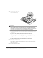
1
magicolor 2200
User’s Guide
®
1800616-001B
Trademarks
The following are registered trademarks of MINOLTA-QMS, Inc.: QMS, the MINOLTA-QMS
logo, and magicolor.
Minolta is a trademark of Minolta Co., Ltd. Other product names mentioned in this manual may
also be trademarks or registered trademarks of their respective owners.
Proprietary Statement
The digitally encoded software included with your printer is Copyrighted © 2000 by MINOLTAQMS, Inc. All Rights Reserved. This software may not be reproduced, modified, displayed,
transferred, or copied in any form or in any manner or on any media, in whole or in part,
without the express written permission of MINOLTA-QMS, Inc.
Copyright Notice
This manual is Copyrighted © 2000 by MINOLTA-QMS, Inc., One Magnum Pass, Mobile, AL
36618. All Rights Reserved. This document may not be copied, in whole or part, nor
transferred to any other media or language, without written permission of MINOLTA-QMS, Inc.
Manual Notice
MINOLTA-QMS, Inc. reserves the right to make changes to this manual and to the equipment
described herein without notice. Considerable effort has been made to ensure that this manual
is free of inaccuracies and omissions. However, MINOLTA-QMS, Inc. makes no warranty of
any kind including, but not limited to, any implied warranties of merchantability and fitness for
a particular purpose with regard to this manual. MINOLTA-QMS, Inc. assumes no
responsibility for, or liability for, errors contained in this manual or for incidental, special, or
consequential damages arising out of the furnishing of this manual, or the use of this manual
in operating the equipment, or in connection with the performance of the equipment when
so operated.
Registering the Printer
Mail—Fill out and send in the registration card enclosed in your shipment.
Internet—www.qms.com/support/prodreg (US only)
Contents
Replacing Consumables .................................................................................7
Consumable Life Expectancies 8
Replacing Consumables 8
Replacing Toner Cartridges 9
Replacing the OPC Drum, Laser Lens Cover, and Waste Toner Pack 13
Replacing the Fuser Unit and Transfer Roller Kit 20
Replacing the Fuser Oil Roller 26
Replacing the Transfer Belt 28
Using Media....................................................................................................33
Introduction 34
Media Handling 34
Media Types 35
Loading Media 40
Media Storage 47
Maintaining the Printer ......................................................................................... 49
Maintaining the Printer 50
Cleaning 52
Troubleshooting ..................................................................................................... 53
Introduction 54
Printing a Status Page 54
Preventing Media Jams 54
Automatic Jam Recovery 55
Understanding the Media Path 56
Clearing Media Jams 57
Solving Problems with Media Jams 69
Solving Other Problems 71
Solving Problems with Printing Quality 75
Status, Error, and Service Messages 85
Additional Assistance 97
Installing Other Accessories ..................................................................................99
Introduction 100
BuzzBox 106
Antistatic Protection 109
Dual In-Line Memory Modules 109
Emulations, Fonts, and Other Software 114
Kanji Font Internal IDE Hard Disk 118
QFORM 120
Interfaces and Daughterboards 121
SCSI Interface 124
Internal IDE Hard Disk Drive 126
Media Trays 128
Printer Stand/Cabinet 129
SC-210 Convenience Copier 129
Time-of-Day Clock (Standard on Models EN and DP) 129
4
Color Printing ...................................................................................................133
Introduction 134
Repacking the Printer ......................................................................................137
Storing the Printer 138
Relocating Your Printer 138
Repacking the Printer 139
Technical Specifications .................................................................................. 145
Requirements 146
Engine and Controller Specifications 150
Print Media 155
Document Option Commands 156
Supported DOCs 156
Contents
5
Replacing Consumables
1
The stated life expectancy of each consumable is based on printing under specific
operating conditions, such as media type, number of color planes, page size, and page
coverage (@ normal 5% coverage of letter/A4-size media). The actual life expectancy will
vary depending on these and other printing variables, including continuous or intermittent
printing, ambient temperature, and humidity. For further information about the
consumables statistics page and replacement menus, refer to the CrownBook.
Failure to follow instructions as outlined in the User’s Guide could result in voiding
your warranty.
The following messages indicate that a consumable needs to be replaced:
REPLACE OIL ROLLER
FUSER OIL LOW, FUSER OIL EMPTY, "#
$#%
REPLACE OIL ROLLER &
!!
'(
REPLACE FUSER UNIT
)
*)+(
,
-!.!
!
"#
/
0#
1%
$23
($23
!(
REPLACE OPC DRUM
REPLACE WASTE TONER
WASTE TONER NEAR FULL
/4
56+7
56+7
$
"#
$2389
93!
:0
2(%4
Item/Message Display
This item needs replacing by user after... Page Reference
Toner
<COLOR> TONER EMPTY
Approximately 6,000 single-sided pages per “Replacing Toner
cartridge—black, yellow, magenta, cyan at Cartridges” on
5% coverage of each color.
page 9
Transfer belt
REPLACE TRANSFER BELT
100,000 single-sided images (1:1 color/
monochrome printing)
“Replacing the
Transfer Belt” on
page 28
*A plane (also called an image) is a single pass of the OPC drum (one toner color). For example,
a black-only, single-sided (simplex) print job makes one pass, and a two-color (duplex) print job
makes two passes. A single-sided color page (also called a face) consists of four passes of the
OPC drum, since most color print jobs use all four toner colors. A two-sided color page may consist
of up to eight passes of the OPC drum, since most color print jobs use all four toner colors. Stated
consumable life is expressed at 5% in simplex letter/A4 pages. A duplex page is equivalent to two
simplex pages.
The number of sheets/faces printed shown on the startup page differs from the number of sheets/
faces printed statistics in CrownView and on the consumables statistics page (Operator Control/
Consumables/Print Statistics). The numbers on the startup page refer to number of sheets/faces
printed during the lifetime of the printer. The numbers in CrownView and on the consumables statistics page refer to the number of sheets/faces printed to date during the current consumables
tracking period (Administration/Consumables/Start Period menu).
Ordering Consumables
Choosing the right consumables for your magicolor 2200 printer not only increases its
reliability and performance, but also minimizes the risk of damage.
For example, only MINOLTA-QMS toner cartridges are designed to meet the exact
specifications of your MINOLTA-QMS printer, giving maximum performance, efficiency,
and long life.
Toner cartridges and other consumables for the magicolor 2200 are available from your
local vendor or Q-SHOP (www.q-shop.com). See the Service & Support Guide for the
telephone number of the MINOLTA-QMS office nearest you for information on ordering.
Replacing Toner Cartridges
Characters and images are created in your laser printer through a process that applies toner
to the photosensitive (OPC) drum (which functions like photographic film). Your printer
Replacing Toner Cartridges
9
uses four toner cartridges: black, yellow, magenta, and cyan. Handle the toner cartridges
carefully to avoid spilling toner inside the printer or on yourself.
5"
The carbon-particle toner is nontoxic. If you get toner on your hands, wash them in cool
water or a neutral detergent. If you get toner on your clothes, lightly dust them off as
much as possible. If some toner remains on your clothes, use cool, not hot water, to
rinse the toner off, provided your clothing is washable.
Attention
If you get toner in your eyes, wash it out immediately and consult a doctor. Material
Safety Data Sheets (MSDS) information can be found at www.minolta-qms.com
(click on the Answer Base).
Toner Cartridge Life
A toner cartridge contains enough toner (yellow, magenta, cyan, or black) to print a
maximum of 6,000 (@ normal 5% page coverage) letter/A4-size pages.
When toner runs low in a cartridge, X TONER LOW displays in the message window (X
indicates the toner color). It’s your option whether to continue printing; usually, parts of
the page print lighter.
When toner is low, it’s sometimes helpful to take the cartridge out of the printer and
redistribute the toner by gently rocking the cartridge horizontally side to side (as you do
for a new cartridge) five or six times. Then reinstall the cartridge.
The printer, approximately 100 pages after detecting that toner in a cartridge is low,
displays X TONER EMPTY in the message window (X indicates the toner color). Printing
continues even though the out-of-toner warning appears. However, the color gradually
fades, so replace the toner cartridge as soon as possible.
10
Replacing Toner Cartridges
Toner Cartridge Handling
Attention
Do not hold a toner cartridge vertically. Do not touch the
toner roller surface c or the protective shutter d. This
could lower image quality.
c d
Keep toner cartridges:
„
In their packaging until you’re ready to install them.
„
In a cool, dry location away from sunlight (due to heat).
The maximum storage temperature is 95° F (35° C) and the maximum storage humidity is 80% without condensation.
„
Level during storage.
Do not stand or store cartridges on their ends or turn them upside down; the toner
inside the cartridges may become caked or unequally distributed.
„
Away from salty air and corrosive gases such as aerosols.
„
Away from disk drives and floppy disks.
The magnets in the cartridges can damage stored data.
Toner Cartridge Replacement
1
2
Check the message display to see what toner color is out.
Open the printer’s front cover.
Attention
Be careful not to spill toner on the inside of the printer’s front cover. Toner will
fall from there into the upper media tray. If toner does fall onto the open cover,
immediately wipe it with a dry, lint-free soft cotton cloth or swabs.
If the toner cartridge you want to replace is the one showing, go to step 5. If not, go
to step 3.
Replacing Toner Cartridges
11
3
Press the toner cartridge carrousel button
c and release the button d before turning
the carrousel dial e counterclockwise until
it stops.
The carrousel rotates 90° and stops.
The toner cartridge carrousel may start to
turn automatically from the weight of the
inserted toner cartridge. Make sure you
have fully turned to the next slot before trying to insert another toner cartridge.
4
Continue step 3 until the color to be
replaced is visible.
5
Pull the release lever to eject the toner
cartridge you are going to replace.
2
1
3
5" Dispose of it properly according to your
local regulations (do not dispose of it by
burning).
6
12
Remove the new toner cartridge from its
shipping carton.
Replacing Toner Cartridges
7
Distribute the toner inside the cartridge.
Holding a cartridge with both hands, gently shake it
five or six times.
5" Each toner cartridge has a colored end that
corresponds to a colored label inside the cartridge slots. Always install the toner
cartridge in the slot with a label of the same color.
8
Place the front end of the toner cartridge
installation guides into the cartridge installation rails on the cartridge carrousel.
9
10
Gently push the new cartridge into the printer.
Close the printer’s front cover.
Refilled Toner Cartridges
Attention
Refilled toner cartridges may produce variations in toner quality and reliability and
can reduce the print quality of your documents. Any damage to the printer or quality
problems caused by a refilled toner cartridge use will void your warranty.
Replacing the OPC Drum, Laser Lens Cover, and Waste
Toner Pack
Attention
The OPC drum is extremely sensitive to bright light and direct sunlight. Always
leave it in its protective bag until you’re ready to install it. Any exposure to light
should be avoided, or permanent damage could result. Any damage resulting from
mishandling of the OPC drum will void the warranty of the OPC drum. Also, handle
the cartridge carefully by its sides so you don’t touch the surface (the green part) of
the drum. The drum is also extremely sensitive to hand oils and scratches, both of
which reduce print quality.
Replacing the OPC Drum, Laser Lens Cover, and Waste Toner Pack
13
When the OPC drum is worn out, the message REPLACE DRUM appears. The printer will
not print until the drum kit is replaced.
When you replace the OPC drum cartridge after a DRUM LOW or REPLACE DRUM
message displays in the message window, the printer automatically recovers. However, the
replaced waste toner pack consumables monitoring system must be reset.
The three items below are included in the OPC drum kit. If one needs replacing, replace
all three items.
„
Waste toner pack
„
OPC drum cartridge
„
Laser lens cover
5"
The OPC drum life is directly related to the number of rotations of the drum. Longest
drum life is achieved with continuous printing. Intermittent printing with small job sizes
requires cleaning rotations before and after each job, and subsequently will impact
OPC life.
The steps are:
„
Removing the used waste toner pack
„
Removing the used OPC drum cartridge
„
Replacing the laser lens cover
„
Installing the new OPC drum cartridge
„
Installing the new waste toner pack
Removing the Used Waste Toner Pack
When the waste toner pack is nearly full, the message “WASTE TONER NEAR FULL”
appears. Prepare to replace the entire OPC drum kit.
1
2
14
Turn off the printer.
Open the printer’s front cover.
Replacing the OPC Drum, Laser Lens Cover, and Waste Toner Pack
3
Carefully remove the waste toner pack using
the handle.
Keep the waste toner pack upright so the
toner does not spill.
4
Turn the two caps labeled “A” counterclockwise and remove them.
5
Twist the two “A” caps c onto the two “A”
holes d.
Turn the caps clockwise to secure them.
11
11
22
22
Replacing the OPC Drum, Laser Lens Cover, and Waste Toner Pack
15
6
Remove waste toner pack cap labeled “B” and insert
it into hole “B.”
7
Dispose of the used waste toner pack.
5" Dispose of it properly according to your local
regulations (do not dispose of it by burning).
8
Continue with replacing the OPC drum
cartridge.
Reinstall the new waste toner pack after replacing
the OPC drum.
Removing the Used OPC Drum Cartridge
1
With the front cover open, rotate the transfer belt unit left release lever counterclockwise to the top (12 o’clock) position.
This raises the transfer belt unit.
2
16
Hold the OPC drum cartridge handle and
carefully pull it out about 8 inches (20 cm).
Replacing the OPC Drum, Laser Lens Cover, and Waste Toner Pack
3
Support the bottom of the drum with your
hand, then carefully pull the cartridge toward
you and remove it.
5" Dispose of it properly according to
your local regulations.
Replacing the Laser Lens Cover
1
Press on the laser lens cover lock release lever and
gently pull the laser lens cover toward you.
5" Dispose of it properly according to your local
regulations.
2
Remove the new laser lens cover from the OPC
drum kit box.
Attention
Do not touch the glass surface of the laser lens.
3
Place the front end of the laser lens cover into
its installation rail.
4
Carefully insert the laser lens cover and
check to make sure it is fully inserted.
Attention
If the laser lens cover is not properly installed, serious damage to the printer
could result.
Replacing the OPC Drum, Laser Lens Cover, and Waste Toner Pack
17
Installing the New OPC Drum Cartridge
1
Remove the new OPC drum cartridge from
its shipping box.
Attention
Keep the protective sheet on the cartridge. Do not touch the protective sheet on
the photosensitive (green) surface or scratch the surface. This could lower
image quality.
Make sure the transfer belt left release lever is still set to its top position
(12 o’clock).
2
Hold the OPC drum cartridge level, place
the front end of the OPC drum cartridge
installation guide into the installation rail.
3
Carefully push the OPC drum cartridge in.
Attention
The cartridge should slide easily into the printer. Don’t force it.
18
Replacing the OPC Drum, Laser Lens Cover, and Waste Toner Pack
4
Press on the front handle of the OPC drum cartridge with one hand and hold the front handle of
the OPC protective cover with the other hand.
5
Peel the protective cover off (straight toward
you).
5" Dispose of it properly according to your local
regulations.
6
Turn the left release lever of the transfer belt
clockwise to its correct position (2 o’clock).
This lowers the transfer belt.
Also make sure the transfer belt right release
lever is set to its correct position (10 o’clock).
Attention
If the transfer belt left release lever is at its top position (12 o’clock), the waste
toner pack cannot be installed.
Installing the New Waste Toner Pack
1
Remove the new waste toner pack from the drum kit box.
Replacing the OPC Drum, Laser Lens Cover, and Waste Toner Pack
19
2
Insert the bottom of the waste toner pack c
into its installation position in the printer.
3
Insert the top of the waste toner pack d
into its installation position in the printer
until it is firmly seated.
4
Close the printer’s front cover.
2
If the waste toner pack is not correctly
installed or the transfer belt right release
lever is at its top position (12 o’clock), the
front cover cannot be closed. Turn on the
printer.
5
1
In the Operator Control/Consumables/Items Replaced/Waste Toner menu, choose
Yes to reset the consumables monitoring system.
Replacing the Fuser Unit and Transfer Roller Kit
WARNING!
The fuser unit is hot. When the top cover is opened, the fuser unit temperature
drops gradually (one hour wait time). Do not replace the fuser oil roller until you
are sure that the fuser unit has cooled down.
When the fuser is worn out, the message “REPLACE FUSER UNIT” appears and the
printer does not print. Replace the fuser kit. After the new fuser kit is installed, printing
automatically resumes.
The fuser kit includes the two items below. When replacing the fuser unit, replace the
transfer roller as well.
20
„
Fuser unit
„
Transfer roller unit
Replacing the Fuser Unit and Transfer Roller Kit
Replacing the Fuser Unit
1
2
3
Turn off the printer.
4
Remove the fuser oil roller.
Open the printer’s top cover.
Rotate the two fuser oil roller lock levers to
release the fuser oil roller.
Hold it by the green handle only.
5
Place the fuser oil roller on a table or level surface.
Attention
Since the fuser oil roller removed here is to be
installed in the new fuser unit, handle it with care.
If you set the fuser oil roller on the table do it as
shown in the illustration. Do not allow the roller
surface to contact the table or get dirty. This could
lower image quality.
Replacing the Fuser Unit and Transfer Roller Kit
21
6
Turn the release levers (front, rear) to
release the fuser unit.
7
Holding the fuser unit handles,
lift up the unit.
5" Dispose of it properly according
to your local regulations.
8
22
Remove the new fuser from its
shipping box.
Replacing the Fuser Unit and Transfer Roller Kit
9
Carefully lower the new fuser unit so that the two pins in the fuser unit installation
section go into the two installation holes in the fuser unit.
10
Press in on the fuser unit release levers c and
rotate them downward d.
This secures the fuser unit.
11
22
11
22
Attention
If the fuser unit release levers are not set correctly, the fuser oil roller cannot be
installed. Set the fuser unit release levers to the fixed position.
Replacing the Fuser Unit and Transfer Roller Kit
23
11
Reinstall the fuser oil roller (removed
in step 4).
12
Rotate the two oil roller levers to lock
the oil roller into place.
13
Close the printer’s top cover.
Check the release button to make sure the top cover is properly closed.
Replacing the Transfer Roller Unit
5"
1
24
If there is media in the multipurpose tray, remove it. Close the multipurpose tray.
Press the right cover release button and carefully open the right cover.
Replacing the Fuser Unit and Transfer Roller Kit
2
Holding the two transfer roller unit handles,
remove the transfer roller unit.
5" Dispose of it properly according to your local
regulations.
3
Remove the new transfer roller unit from the
fuser kit box.
Attention
Do not touch the surface of the transfer
roller unit. This could lower image quality.
4
Place the new transfer roller unit on a
level surface.
5
Lift up the two transfer roller unit handles.
6
Holding the two transfer roller unit handles, carefully lower it so the transfer roller unit shaft goes
into the two transfer roller unit installation
guides.
Replacing the Fuser Unit and Transfer Roller Kit
25
7
8
Lower the two transfer roller unit handles.
Carefully close the right cover.
Check the release button status to make sure
the cover is properly closed.
9
If necessary, reopen the multipurpose tray
and put the media back in.
Replacing the Fuser Oil Roller
The fuser oil roller provides a lubricant for the printer via an oil-impregnated roller. This
oil is necessary for the proper functioning of the printer.
WARNING!
The fuser unit is hot. When the top cover is opened, the fuser unit temperature
drops gradually (one hour wait time). Do not replace the fuser oil roller until you
are sure that the fuser unit has cooled down.
When the fuser oil roller is worn out, the message “REPLACE OIL ROLLER” appears
and the printer does not print. Replace the fuser oil roller. After the new roller is installed,
printing automatically resumes.
5"
26
When you replace the fuser oil roller after a REPLACE OIL ROLLER message
displays in the message window, the printer automatically recovers.
Replacing the Fuser Oil Roller
1
2
3
Turn off the printer.
Open the printer’s top cover.
Rotate the two fuser oil roller lock levers to
release the fuser oil roller.
5" Dispose of it properly according to your local
regulations.
4
Remove the new fuser oil roller from its
shipping box.
Attention
If you set the new fuser oil roller on a table, do it as shown in
the illustration. Do not allow the roller surface to contact the
table or get dirty. This could lower image quality.
5
Insert the new fuser oil roller
installation guides (front, rear)
into the fuser unit installation
rail.
6
Carefully lower the roller.
Replacing the Fuser Oil Roller
27
7
Rotate the two oil roller levers to lock the oil
roller into place.
Attention
If the two fuser oil roller release levers are
not correctly set, the top cover cannot be
closed. Set the release levers to the roller
fixed position.
8
Carefully close the top cover.
Check the release button to make sure the
top cover is properly closed.
9
Turn on the printer.
Replacing the Transfer Belt
When the transfer belt is at its end of life, the message “REPLACE TRANSFER BELT”
appears, and the printer does not print. Replace the transfer belt. After the new transfer
belt is installed, printing automatically resumes.
1
2
3
28
Open the printer’s front cover.
Remove the waste toner pack.
Rotate the left transfer belt lock lever.
Replacing the Transfer Belt
4
Remove the OPC drum cartridge and set it
aside.
Attention
The OPC drum is extremely sensitive to bright light and direct sunlight. Always
put it in its protective bag until you’re ready to reinstall it. Any exposure to
light should be avoided, or permanent damage could result.
Also, handle the cartridge carefully by its sides so you don’t touch the surface
(the green part) of the drum. The drum is also extremely sensitive to hand oils
and scratches, both of which reduce print quality.
5
Rotate the left lever to its 4 o’clock position.
Replacing the Transfer Belt
29
6
Grasp the handles of the transfer belt and remove it.
5" Dispose of it properly according to your local regulations.
7
Remove the new transfer belt from its packaging and insert it into the printer.
8
Press on the transfer belt front handle with
one hand, take the handle of the transfer belt
fixture with your other hand, and pull the fixture straight toward you.
5" Dispose of it properly according to your
local regulations.
30
Replacing the Transfer Belt
9
Rotate the transfer belt lock lever.
10
Reinstall the OPC drum cartridge.
Replacing the Transfer Belt
31
11
12
Close the transfer belt lock lever.
13
14
Reinstall the waste toner pack.
Check to make sure the laser lens cover is
firmly seated.
Close the front cover and turn on the printer.
2
1
32
Replacing the Transfer Belt
Using Media
2
Introduction
This chapter provides information on handling, selecting, and storing media. Refer to the
Maintenance Guide for media specifications.
Media Handling
Before purchasing a large quantity or special media, do a trial printing with the same
media and check print quality. Check with our web site www.minolta-qms.com for a list of
current approved media.
Attention
Do not use the media types listed below. These could cause poor print quality, media
jams, or damage to the printer.
Do not use media that is
„
Not approved
„
Meant for ink jet printers
„
Folded, embossed, warped, or wrinkled
„
Perforated or prepunched
„
Too slick, too coarse
„
Composed of foil or gilt
„
Coated with a processed surface (such as carbon paper, heat-sensitive paper, heatpressure paper)
„
Irregularly shaped (not rectangular); not uniform in size
„
Bound with glue, tape, or paper clips
„
Attached to ribbons, hooks, buttons, etc.
Do not use envelopes that have
„
34
Sticky flaps
Introduction
„
Metal clasps, fasteners, transparent windows, peel-off strips for sealing
„
Material that will melt, vaporize, offset discolor, or emit dangerous fumes
Do not use labels that have
„
Label(s) already peeled off
„
Labels that peel off easily
„
Glue or sealer that might come off
„
Material that will melt, vaporize, offset discolor, or emit dangerous fumes
Media Types
Plain Paper
Formatting
Format data within your application.
Input
Upper and
Optional Trays
500 sheets of 20 lb bond (75 g/m²) paper (letter/A4/legal)
each; capacity for other weights varies accordingly.
Multipurpose
Tray
150 sheets of 20 lb bond (75 g/m²) paper; capacity for other
weights varies accordingly.
Upper and
Optional Trays
Simplex—Face up; Duplex—Face down
Multipurpose
Tray
Simplex—Face down; Duplex—Face up
Orientation
Type
Any standard or recycled office paper suitable for plain-paper laser printers,
such as
„ Hammermill Laser Print
„ Georgia-Pacific Microprint Laser 1000
„ Neusiedler Color Copy 90
„ Xerox 4024
Weight
16–24 lb bond (60–90 g/m²)
Duplexing
Up to 28 lb bond (105 g/m²)
Media Types
35
Letterhead and Memo Media
Formatting
Format letterhead or memo data within your application. Try printing your data on
a plain sheet of paper first to check placement.
Input
Upper and
Optional Trays
Up to 500 sheets
Multipurpose
Tray
Up to 150 sheets
Upper and
Optional Trays
Face up—top of page toward the right
Multipurpose
Tray
Face down—top of page toward the printer side
Orientation
Type
Any standard or recycled office paper suitable for plain-paper laser printers,
such as
„ Hammermill Laser Print
„ Georgia-Pacific Microprint Laser 1000
„ Neusiedler Color Copy 90
„ Xerox 4024
Weight
16–24 lb bond (60–90 g/m²)
Duplexing
Upper and
Optional Trays
Face down—top of page toward the right
Multipurpose
Tray
Face up—top of page toward the printer side
Notes
Check your application documentation for other information about printing on
letterhead and memo media.
Thick Stock
36
Formatting
Format the information to be printed on the thick stock within your application. Try
printing your data on a plain sheet of paper first to check placement.
Input
Multipurpose
Tray Only
Orientation
Face down
Up to 50 sheets, depending on the thickness of the media
Media Types
Type
For information about thick stock media recommended for your printer, go to
www.minolta-qms.com/support, then click on Answer Base, or contact Technical
Support. See the Service & Support Guide for a complete listing of support
telephone numbers.
Weight
Simplex: 24–43 lb bond (90–163 g/m²)
Autoduplex: Up to 28 lb bond (105 g/m²)
Manual Duplex: 24 lb (90 g/m²) to 43 lb (163 g/m²) bond
Duplexing
Autoduplexing thick stock over 28 lbs (105 g/m²) is not supported. Thicker stock
may be manually duplexed.
Notes
You should test the number of sheets of thick stock the multipurpose tray can hold
to ensure that its performance is acceptable.
43 lb (163 g/m²) bond is also referred to as 90 lb index stock.
Envelopes
Formatting
Your printer receives the instructions to print on envelopes from your application.
„
Print on the front side only. Some parts of the envelope consist of three layers
of paper—the front, back, and flap. Anything printed in these layered regions
may be lost or faded.
„
See your application documentation for specific information on printing
envelopes.
Input
Multipurpose
Tray Only
Orientation
Face down
Type
Use common office envelopes approved for laser printing with diagonal joints,
sharp folds and edges, and ordinary gummed flaps, such as
„ Commercial #10: Columbian Recycled COR02
Duplexing
Not supported
Up to 50, depending on the thickness of the envelopes
„ International DL: Auto Fil #01914
Notes
„ You can print only on the address side of the envelope.
„ Envelopes should be dry.
„ Do not preload or preseal envelopes.
Media Types
37
Labels
Formatting
Format label data within your application. Try printing your data on a plain sheet
of paper first to check placement.
Input
Multipurpose
Tray Only
Orientation
Face down
Type
Use only labels recommended for laser printers, such as
Up to 50 sheets, depending on the thickness of the labels
„ Avery 5260
Weight
16–90 lb (60–163 g/m²)
Duplexing
Not supported
Notes
„
Avoid using labels with exposed adhesive; it may stick to the transfer belt or
the fuser roller, causing labels to peel off and media jams to occur.
„
Adhesive label stock is supported only in letter or A4 sheets.
„
A label consists of a face sheet (the printing surface), adhesive, and a carrier
sheet
—
The face sheet must follow the plain paper specification.
—
The face sheet surface must cover the entire carrier sheet, and no
adhesive should come through on the surface.
„
You can print continuously with label paper. However, this could affect the
media feed, depending on the media quality and printing environment. If
problems occur, stop the continuous print and print one sheet at a time.
„
Check your application documentation for other information on
printing labels.
Postcards
38
Formatting
Format postcard data within your application. Try printing your data on a plain
sheet of paper first to check placement.
Input
Multipurpose
Tray Only
Orientation
Face down
Type
Use only postcards recommended for laser printers
Weight
16–90 lb (60–163 g/m²)
Duplexing
Not supported
Up to 50 sheets, depending on the thickness of the postcards
Media Types
Notes
If the postcard is warped, press on the warped area before
putting in multipurpose tray.
Transparencies
Formatting
Format the information to be printed on the transparencies within your
application. Try printing your data on a plain sheet of paper first to check
placement.
Input
Location
Upper and Optional Trays
Multipurpose tray
Capacity
Up to 50 sheets, depending on the thickness of the
transparencies
If you have problems feeding 50 sheets, try loading only 5–10
sheets at a time. Loading a large number of transparencies at a
time may cause static buildup, thus causing feeding problems.
Orientation
Upper and
Face up
Optional Trays
Multipurpose
Tray
Type
Face down
Use any full-color transparencies (also known as OHP film) that meet normal
photocopier standards. We recommend
„ Q-Media Transparency Media for the magicolor 2200 for color printing
„ 3M PP2500 for monochrome printing
Duplexing
Media Types
Not supported
39
Notes
„
If you touch the face of transparencies with your bare hands, print quality
may be affected.
„
Do not handle transparency media too much. Do not fan transparency media
before loading it. Resulting static electricity may cause printing errors.
„
Keep the media path clean. Transparencies are especially sensitive to a dirty
media path. If there are shadows on either the top or the bottom of the
sheets, see “Cleaning the Printer Interior” in the Maintenance Guide.
„
You can print continuously with transparencies. However, this could affect the
media feed, depending on the media quality and printing environment. If
problems occur, stop the continuous print and print one sheet at a time.
„
Check your application documentation for other information about printing on
transparencies.
Loading Media
Take off the top and bottom sheets of a ream of
paper. Holding a stack of approximately 250
sheets at a time, fan the stack to prevent static
buildup for the paper before inserting it in a tray.
5"
OHP
Do not fan transparency media.
Attention
Always load the media short edge first.
Attention
Do not mix media of different sizes, types, or weights, as this will cause
printer jamming.
„
40
When refilling media, first remove any media remaining in the tray. Stack it with the
new media, even the edges, then reload it. Although the magicolor 2200 was designed
Loading Media
for printing on a wide range of media types, it is not intended to print exclusively on a
single media type except plain paper. Continuous printing on media other than plain
paper (such as envelopes, labels, thick stock, or transparencies) may adversely affect
print quality or reduce engine life.
„
For media other than standard plain paper or transparencies, both the driver (Paper
tab, Paper Type option) and the MP Size key on the control panel need to be selected.
It is important to use the MP Size key to set the multipurpose tray to the appropriate
media size in order to obtain optimum printing results.
Autoduplexing
Duplex (2-sided) printing can be done automatically with the optional duplex unit
installed.
5"
Only up to 28 lb bond (105 g/m²) plain paper can be duplexed.
If you are printing duplex from the upper or optional tray, load the media printing-side
down with the top of the media (or letterhead or memo information) toward the right side
of the tray. If you are printing duplex from the multipurpose tray, load the media
printing-side up with the top of the media toward the printer. Set the driver, for example:
1
In the printer driver, make sure you have selected Duplexer and clicked on the
Add button.
2
In the printer driver, select Simplex (1-sided pages), or Long Edge (flipped horizontally as in a loose-leaf notebook), or Short Edge (flipped vertically as on a clipboard)
as the Duplex option.
3
Click OK.
Upper and Optional Media Trays
1
Slide the media tray open.
Loading Media
41
2
Push the media pressure plate down to lock it
in position.
3
Adjust the media guides to fit the size paper you’re loading.
Squeeze the retainers, move the guides to the appropriate location (media sizes are
listed on the tray), and release the retainers. The media should fit easily between
the guides.
42
Loading Media
4
Load the paper face-up, short edge toward the
right of the tray.
Often, an arrow on the media package label
indicates the printing-side of the media.
Do not overfill the tray.
A fill limit mark is provided on the inside of
the tray. The media tray holds 500 sheets of
20 lb bond (75 g/m²) paper.
Make sure that the paper fits easily between
the guides and the paper corners are under the
left and right media-separating tabs and are
not bent.
Attention
Always readjust the media guides after inserting the media. Improperly
adjusted guides may cause poor print quality, media jams, or printer damage.
Loading Media
43
5
Slide the tray back into the printer.
5" If you have removed the tray from the
printer, slightly tilt up the tray to insert
it into the installation rails to slide it
back in.
Multipurpose Tray
Page sizes other than letter, A4, and legal can be printed only from the multipurpose tray
(also known as tray 1). Use the MP (Multipurpose) Size key on the control panel to set the
page size.
Other special types of media (such as thick stock, transparencies, and envelopes) are also
fed from the multipurpose tray. See “Media Specifications” in the Maintenance Guide for
more information about media.
1
44
Open the multipurpose tray on the right side
of the printer.
Loading Media
2
Open the media support.
Attention
Load only one type/size of media per tray at a time.
Load the media face down, short edge toward the printer.
FA
C
DO E
WN
3
Often, an arrow on the paper package label
indicates the face-up (printing) side of the
paper.
A fill limit mark is provided on the inside of the
media guides on the multipurpose tray. The
multipurpose tray holds 150 sheets of 20 lb
bond (75 g/m²) paper.
Loading Media
45
4
Adjust the media guides to fit the size media
you’re loading.
LTR
LG .
EXE. L.
A5
B5
A4
Attention
Always adjust the media guides after inserting the media. A guide that is not
properly adjusted can cause poor print quality, media jams, or printer damage.
5
Specify the media size in the multipurpose tray by using the MP Size key on the
control panel.
Printing Envelopes from the Multipurpose Tray
1
2
3
4
Flex the envelope stack (including the edges) to remove any stiffness.
Place the envelopes on a flat surface, and flatten them by pressing down the corners.
Correct any bent corners, and then tap the envelopes on a flat surface to align them.
Place the envelope stack into the multipurpose tray with the flap-side up.
Check your application documentation to determine if the flap should be placed on
the left or on the right. Print a single envelope to check the orientation before printing multiple copies.
46
Loading Media
5
Adjust the media guides to the width of the envelopes.
Make sure the guides are snug enough to keep the envelopes straight, but not so tight
that they buckle the envelopes.
6
Open the flap of each envelope immediately (before it cools) after the envelope is
delivered to the output tray.
5" Because the envelopes pass through heated rollers, the gummed area on the flaps
may seal. Using envelopes with emulsion-based glue avoids this problem.
Printing Area
The printing area on all media sizes is up to about 0.157 inch
(4 mm) from the edges of the media.
Media Storage
When storing media, avoid:
„
Direct sunlight
„
Excess heat and humidity
„
Dust
If media has been removed from its wrapper, place it in its original packaging and store in a
cool, dark place on a level surface.
Media Storage
47
Maintaining the Printer
3
Maintaining the Printer
Handle the printer with care to preserve its life. Abuse may cause damage and void
your warranty. If dust and paper scraps remain on the inside or outside of the printer,
printer performance and print quality will suffer, so the printer should be cleaned
periodically. Keep the following guidelines in mind:
„
When cleaning the printer, always turn it off (O) and unplug it. Disconnect all
interface cables before cleaning inside the printer.
If you have an optional 5-bin mailbox installed, turn the printer off first, then turn
off the mailbox.
„
Either clean the printer before use, or allow time after unplugging it to allow the
fuser unit to cool down.
Attention
The fuser unit is hot. When the top cover is opened, the fuser unit
temperature drops gradually (one hour wait time).
„
Be careful when cleaning the inside or removing paper jams, as the fuser unit and
other internal parts may become very hot.
„
Do not place anything on the top of the printer.
„
Use a soft cloth to clean the printer.
WARNING!
Do not spill water or detergent into the printer; otherwise the printer will be damaged
and an electric shock may occur.
50
„
Never spray cleaning solution directly on the printer’s surface; the spray could
penetrate through the air vents of the printer and damage the internal circuits.
Avoid using abrasive or corrosive solutions or solutions that contain solvents,
(such as alcohol and benzene) to clean the printer.
„
Always test any cleaning solution (such as mild detergent) on a small area of your
printer to check the solution's performance.
Maintaining the Printer
„
Never use sharp or rough implements, such as wire or plastic cleaning pads.
„
Always close the printer covers gently. Never expose the printer to vibrations.
„
Do not put a cover on the printer immediately after using it. Turn it off and wait until it
cools down.
„
Do not leave the printer’s covers open for any length of time, especially in well-lit
places; light may damage the OPC drum cartridge.
„
Do not open the printer during printing.
„
Do not tap paper stacks on the printer.
„
Do not tilt, lubricate, or disassemble the printer.
„
Do not touch the electrical contacts, gears, or laser beam devices. Doing so may damage the printer and cause the print quality to deteriorate.
„
Keep media in the output tray at minimum level. If the media stacks too high, your
printer may experience media jams and excessive media curl.
„
Lift the printer from the bottom only, using the carrying grips and the carrying bars.
Make sure two people are available to lift the printer when moving it.
When moving the printer, keep the printer level to avoid toner spillage.
„
If you get toner on your skin, wash it off with cool water and neutral detergent.
WARNING!
If you get toner in your eyes, wash it out immediately with cool water and consult a doctor.
Material Safety Data Sheets (MSDS) information can be found at www.minolta-qms.com
(click on the Answer Base).
„
Read all caution and warning labels carefully, making sure to follow any instructions
contained in them. These labels are located on the inside of the printer’s covers and
the interior of the printer body.
„
Make sure any parts removed during cleaning are replaced before you plug in
the printer.
See Chapter 7, “Repacking the Printer,” for printer storing and shipping instructions.
Maintaining the Printer
51
Cleaning
You should perform a thorough cleaning every 30,000 single-sided pages or 12 months,
whichever comes earlier.
Always test any cleaning solution (such as a mild detergent) on a small area of your printer
to check the solution’s performance.
Use
Avoid
A soft dry cloth to clean the
control panel
Sharp or rough implements (such as wire or plastic
cleaning pads)
A soft damp cloth to clean the printer
Sharp or rough implements (such as wire or plastic
cleaning pads)
Mild detergent to clean the
printer
Abrasive or corrosive solutions that contain solvents
(such as alcohol or benzine)
Any liquid
52
This item needs
cleaning...
After...
By...
Duplex unit paper guides
or rollers
Every 30,000 single-sided pages, or 12
months, whichever comes earlier.
Laser lens cover
Removing the waste toner pack to clean
around it or to replace it.
User
See the Maintenance
Guide.
OPC drum cartridge
Every 30,000 single-sided pages, or 12
months, whichever comes earlier.
Paper exit rollers
Every 30,000 single-sided pages, or 12
months, whichever comes earlier.
Printer exterior
As needed.
Printer interior
Every 30,000 single-sided pages, or 12
months, whichever comes earlier.
Registration roller
Every 30,000 single-sided pages, or 12
months, whichever comes earlier.
Transfer roller
Every 30,000 single-sided pages, or 12
months, whichever comes earlier.
Cleaning
Troubleshooting
4
Introduction
This chapter provides information to aid you in resolving printer problems you may
encounter, or at least guide you to the proper sources for help.
Printing a Status Page
Print a status page to verify the printer is printing correctly.
Press Key
(Until) Display Reads
Online
IDLE (and online LED is off)
Menu
OPERATOR CONTROL
Next (
)
ADMINISTRATION
Select
ADMINISTRATION–SPECIAL PAGES
Select
PRINT STATUS
Select
YES
Online
IDLE (and online LED is on)
Preventing Media Jams
Make sure that...
Avoid...
Media matches the printer specifications
Media that is folded, wrinkled, or excessively curled
Media is flat, especially on the leading edge Double feeding (remove the media and fan the
sheets—they may be sticking together)
The printer is on a hard, flat, level surface
Fanning transparencies since this causes static
You have the correct media type selected if Loading more than one type/size/weight of media in a
you’re printing on envelopes, labels, thick
tray at the same time
stock, or transparencies.
You store media in a dry location away from Overfilling the media input trays
moisture and humidity
54
Introduction
Make sure that...
Avoid...
You always adjust the media width regulation guides in the multipurpose tray after
inserting the media (a guide that is not
properly adjusted can cause poor print
quality, paper jams, or printer damage)
Allowing the output tray to overfill (the face-down
output tray has a 500-sheet capacity—jamming may
occur if you allow media to accumulate more than
500 sheets at a time)
You remove transparencies from the output
tray immediately to avoid static buildup.
You load the media (for single-sided pages)
printing-side up in the upper or optional
trays or printing-side down in the multipurpose tray (many manufacturers place
an arrow on the end of the wrapper to
indicate the printing side—if you can’t
determine which side of the media to print
on, remove the media from the tray, rotate
the stack a half-turn, turn the stack over,
and then place it back in the tray)
The printer is on a hard, flat, level surface
Automatic Jam Recovery
The magicolor 2200 provides automatic jam recovery (when enabled through the
Administration/Engine/Page Recovery menu). After you remove any jammed media,
printing automatically resumes from the page the printer stopped at when the jam
occurred.
5"
For automatic jam recovery to work, it is necessary to leave the printer turned on when
you remove the jammed media.
Automatic Jam Recovery
55
Understanding the Media Path
Understanding the printer’s media path will help you locate media jams.
Media exit unit
c
d
e
f
g
h
i
j
k
l
Output tray
Fuser
Transfer belt
OPC drum cartridge
Duplex unit (standard on DP model)
Multipurpose tray
Upper media tray
Lower feeder unit and optional tray (standard on DP model)
5-bin mailbox
c
d
e
f
g
h
i
DP Model
j
k
l
DP Model with
5-bin Mailbox
Simplex
Duplex
56
Understanding the Media Path
Media Tray (Upper Tray Standard on All Models and Optional Tray
Standard on DP Model)
The media tray(s) is (are) located at the bottom front of the printer. The media is picked
from the tray, passed under the OPC drum cartridge and the transfer belt, passed through
the fuser, and delivered via the paper exit unit to the output tray on top of the printer.
Multipurpose Tray (Standard on All Models)
The multipurpose tray is located at the right of the printer. The media is picked from the
multipurpose tray, passed under the OPC drum cartridge and the transfer belt, passed
through the fuser, and delivered via the paper exit unit to the output tray on top of the
printer.
Duplex Unit (Standard on DP Model)
The media is picked from a media tray, passed under the transfer belt, passed through the
fuser, fed into the duplex unit where the media undergoes a change in direction, cycles
through the transfer belt and fuser again, and is delivered via the paper exit unit to the
output tray, which is the top of the printer.
Since several sheets cycle through the printer/duplex unit at the same time, recovering
from a media jam may require the removal of more than one sheet.
To manually duplex, remove the media, flip it over, and reload it.
5-bin Mailbox (Optional on All Models)
The 5-bin mailbox is located on the top of the printer. The media is picked from the tray,
passed under the transfer belt, passed through the fuser, and delivered via the paper exit
unit to the 5-bin mailbox, which is on top of the printer.
Clearing Media Jams
To avoid damage, always remove jammed media gently, without tearing it. Any pieces of
media left in the printer, whether large or small, can obstruct the paper path and cause
further jams. Do not reload media that has jammed.
Clearing Media Jams
57
Attention
The image is not fixed on the media before the fusing process. If you touch the
printed surface, the toner may stick to your hands, so be careful not to touch the
print face when removing the jammed media. Make sure not to spill any toner inside
the printer. Unfused toner can dirty your hands, clothes, or anything else it gets on. If
you accidentally get toner on your hands, wash them in cool water. If you
accidentally get toner on your clothes, lightly dust them off as much as possible. If
some toner remains on your clothes, use cool, not hot water, to rinse the toner off,
provided your clothing is washable. If toner gets on your skin, wash it off with water
or a neutral detergent.
WARNING!
If you get toner in your eyes, wash it out immediately with cool water and consult a doctor.
Material Safety Data Sheets (MSDS) information can be found at www.minolta-qms.com
(click on the Answer Base).
If, after clearing the media jam, the jam message in the control panel window persists,
open and close the printer’s covers. This should clear the jam message.
Handling Media Jams by Location
58
Location of Jam
Page Reference
Tray 1—multipurpose tray
page 60
Tray 2—upper tray
Tray 5—optional tray (lower feeder unit)
page 59
Near OPC drum
page 61
Near duplex unit
page 64
In mailbox
page 67
Clearing Media Jams
Clearing Misfeed (Upper or Optional Tray) Jams
1
Remove the media tray(s).
2
Carefully remove the jammed media.
3
Shuffle the media currently in the tray and
even up the front edges.
4
Reinsert the media printing face up.
Make sure the media is lying flat, is under the media separating tabs, and doesn’t exceed the media limit mark.
Check to see if the media width guides are correct.
5
6
Slide the tray(s) back into the printer.
Open the front cover, then close it.
The media jam display is cancelled.
Clearing Media Jams
59
Clearing Misfeed (Multipurpose Tray) Jams
1
2
Remove the media from in the multipurpose tray.
3
Shuffle the media that was removed in step 1 and
even up the front edges.
4
Reinsert the media printing face down.
Carefully remove the jammed media.
Make sure the media is lying flat and doesn’t exceed the
media limit mark. Check to see if the media width guides
are correct.
5
Open the front cover, then close it.
The media jam display is cancelled.
Clearing Inner Jams, Outer Jams, and Drum Jams
Media Jams inside the Lower Right Door (Vertical Transport Area)
1
2
3
Open the lower right door(s).
Carefully remove the jammed media.
Close the lower right door(s).
The media jam display is cancelled.
60
Clearing Media Jams
Media Jams near the OPC Drum
1
If there is any media in the multipurpose tray, remove it
and close the multipurpose tray.
2
Press the right-side cover release button and carefully
open the cover all the way.
3
Remove the jammed media by pulling it
slowly from the bottom of the fuser.
Attention
Do not pull jammed media from the top of the
printer through the fusing rollers.
This prevents any unfused toner from dirtying
the fuser rollers.
Clearing Media Jams
61
4
Close the right-side cover.
The media jam display is cancelled.
5
6
7
Check the release button to make sure the cover is securely closed.
8
Reinsert the media printing face down.
If media was removed in step 1, open the multipurpose tray.
Shuffle the media that was removed in step 1 and even
up the front edges.
Make sure the media is lying flat and doesn’t exceed
the media limit mark. Check to see if the media width
guides are correct.
Media Jams near the Duplex Unit (Standard on DP Model)
1
Open the top cover.
Attention
Do not pull jammed media from the top of the
printer through the fusing rollers.
This prevents any unfused toner from dirtying
the fuser rollers.
62
Clearing Media Jams
2
Carefully remove the jammed media in the top
cover media reverse area.
3
Open the media jam removal cover with your left
hand and carefully remove the jammed media in
the duplex media feed area with your right hand.
4
Close the media jam removal cover with your left
hand and close the top cover.
5
Check the release button to make sure the door is
securely closed.
6
If the multipurpose tray is closed, open it.
Clearing Media Jams
63
64
7
Pressing the duplex unit cover release, carefully open
the cover.
8
9
10
Remove the jammed media.
11
If there still is a jam message, press the
right-side cover release button and carefully
open the cover all the way.
12
Lift the inner paper guide.
Close the duplex unit’s cover.
Close the multipurpose tray.
Clearing Media Jams
13
Remove the jammed media by pulling it toward you.
If the media came out easily, skip ahead to step 15.
If the media did not come out easily or if you cannot reach the media from this area,
keep the duplex unit’s lower cover open.
14
15
Open the duplex unit cover.
Remove the jammed media by pulling it slowly from the bottom of the fuser rollers.
Be careful not to touch the transfer belt while removing jammed media.
16
17
Close the printer’s top cover.
Close the duplex unit’s paper guide, lower cover, and top cover.
Media Jams near the Fuser Unit
1
Open the top cover.
Attention
Do not pull jammed media from the top of the
printer through the fusing rollers.
This prevents any unfused toner from dirtying
the fuser rollers.
Clearing Media Jams
65
2
3
Carefully remove the jammed media.
4
Close the media jam removal cover.
5
Close the top cover.
Open the media jam removal cover and carefully
remove the media that is jammed there.
Check the release button to make sure the top cover is securely closed.
6
7
Open the right-side cover.
Remove the jammed media by pulling it slowly
from the bottom of the fuser.
Be careful not to touch the transfer belt while
removing jammed media.
66
Clearing Media Jams
8
Close the right-side cover.
Check the release button to make sure the duplex unit
cover is securely closed.
The media jam display is cancelled.
Media Jams in the Optional 5-bin Mailbox
1
Carefully remove the jammed media from the paper
eject area of the mailbox.
2
Open the mailbox door.
Clearing Media Jams
67
3
Lift up the paper jam removal guide in the mailbox
with your left hand, and use your right hand to carefully remove the jammed paper.
4
Close the mailbox door.
The media jam display is cancelled.
Clearing Other Jams
Remove jammed media from the output tray by gently pulling it to the left away from the
media exit area.
68
Clearing Media Jams
Solving Problems with Media Jams
5"
Frequent jams in any area indicate that area should be checked, repaired, or cleaned.
Repeated jams may also happen if you’re using the wrong weight print media.
Symptom Cause
Several
sheets go
through
the printer
together.
Solution
The front edges of the media Remove the media and even up the front edges, then
are not even.
reload it.
The media is moist from
humidity.
Paper jam Front cover needs to be
message opened and closed again to
stays on reset the printer.
Remove the moist media and replace it with new, dry
media.
Open and close the front cover of the printer again.
Some media remains jammed Recheck the paper path and make sure you have
in the printer.
removed all of the media jams.
5-bin mail- The wrong media is being
box jams. used.
Make sure that you are using only plain paper (or
recycled plain paper).
Duplex
The wrong media is being
unit jams. used.
Use only supported media. Refer to the “Media Types”
on page 35.
Make sure that you are using only letter/A4 paper.
Plain paper and thick stock up to 28 lb bond (105 g/m²)
can be autoduplexed if the optional duplex unit is
installed. For heavier weights, manual duplexing is
required. To manually duplex, remove the media, flip it
over, and reload it.
Make sure that you have not mixed media types in your
multipurpose tray.
Do not duplex envelopes, glossy stock, labels, transfer
media, or transparencies.
Media may still be jammed.
Check for media stuck in the paper guides in the duplex
unit’s top cover, and the media supply area on the lower
left of the printer.
If you removed jammed media from near the OPC drum,
reset the OPC drum’s locking levers.
Solving Problems with Media Jams
69
Symptom Cause
Solution
Media is
jamming.
The media is not correctly
positioned in the tray.
Remove the jammed media aand reposition the media
properly in the tray.
The number of sheets in the
tray exceeds the maximum
allowed.
Remove the excess media and reload the correct number of sheets in the tray.
The width regulation guides
are not correctly adjusted to
the media size.
Adjust the regulation guides in the tray to match the size
of the media.
The media in upper or
optional tray is not under the
media separating tabs.
Remove the media and reload it so the front corners are
under the media separating tabs.
Warped or wrinkled media is
loaded in the tray.
Remove the media, smooth it out, and reload it. If it still
jams, do not use that media.
Labels, letterhead, envelopes, Special media must be loaded in the multipurpose tray
postcards, thick stock, or
only.
transfer material are loaded in
the upper or optional tray.
The recommended transparency (OHP) or label paper is
facing the wrong way in the
multipurpose tray.
Load the transparencies or labels according to the manufacturer’s instructions.
Envelopes are facing
Load the envelopes in the multipurpose tray so the the
the wrong way in the multipur- flaps are facing up.
pose tray.
If the flaps are on the short edge, set the envelopes in
the multipurpose tray so that the flaps are on the printer
side.
Multiple sheets of transparRemove the OHP media and load them in the tray one
ency (OHP) media are collect- sheet at a time. Do not fan transparencies before loading
ing static electricity in the tray. them.
70
The media is moist from
humidity.
Remove the moist media and replace it with new, dry
media.
Unsupported media (wrong
size, thickness, type, etc.) is
being used.
Use media that is covered by the printer warranty.
Media supply roller is dirty.
Clean the media supply roller.
Solving Problems with Media Jams
Solving Other Problems
Symptom
Cause
Solution
Data was
sent to the
printer, but it
doesn’t print.
An error message is
displayed in the message
window.
Handle according to the message displayed.
The transfer belt installaRemove the transfer belt. Place the front end of the
tion guide is not set corintermediate transfer unit installation guide (2 locations)
rectly in the installation rail. correctly in the installation rail. Next, lightly push in the
unit. Carefully insert the transfer belt about 6 inches
(152.4 mm). Let go with your right hand that was holding
the top handle of the transfer belt, hold the front handle
with both hands, and carefully push in.
Data indica- Too many typefaces are
tor stays on. being downloaded at the
same time.
Make sure you have enough printer memory.
Printer
resets.
Some applications send a printer prep file to the printer
at the beginning of each document. When this occurs,
other prep files cannot be sent without resetting the
printer. Monitor your activities to see if there is a correlation between your use of a certain application and the
printer resetting. If so, contact the application developer.
Occasionally, software
applications interfere with
each other.
Downloading too many
Additional memory (RAM) or a hard drive, which can be
typefaces can overload the used for font storage, is available and easily installed.
printer memory and cause
the printer to reset to
default.
Printing
takes too
much time.
The printer is set to a slow It takes more time to print with special media. When
printing mode (for example, using regular paper, make sure that the media type is
for OHP, thick stock, or
set properly in the driver.
some other special kind of
media).
The printer is set to power It takes a little time for printing to start in power saving
saving mode.
mode. If you do not want to use this mode, disable it.
The printer memory is
insufficient.
Solving Other Problems
Add more memory.
71
Symptom
Cause
You are
Media or settings are
experiencing not correct.
problems
duplexing.
Solution
Make sure that you are using only plain paper. Do not
duplex envelopes, glossy stock, labels, postcards,
transfer media, or transparencies. Make sure that you
have not mixed media types in your multipurpose tray.
Make sure that your document has more than one page.
Go into the printer’s control panel and make sure that
duplex is an available option.
In the printer driver, choose Short Edge (flipped as on a
clipboard) or Long Edge (flipped as in a loose-leaf notebook). Make sure that you are using correct media.
Make sure that all of the covers are closed. Open and
then close the covers to confirm that they are securely
closed.
If you turned the printer off, make sure that you have
turned the printer on again and waited for it to warm up
Transfer belt The OPC drum unit is
cannot be
installed.
removed.
The transfer belt left
release lever is not set in
the transfer belt removal
position.
Remove the OPC drum unit first, then remove the transfer belt.
You are
The wrong media is being
experiencing used.
problems
with the 5-bin
mailbox.
Make sure that you are using only letter/A4 plain paper.
The printer
pauses.
After 100 1-sided pages of a continuous print run, the
magicolor 2200 automatically pauses to do an AIDC
cycle. This process is provided to make sure reliable
printer operation with optimum output quality.
The printer pauses for the
Auto-Image Density Control (AIDC) cycle.
A blank
The toner cartridge is
startup page empty or missing.
ejects or
blank pages
come out
during a
The wrong media is being
printing job
used.
72
Turn the transfer belt left release lever clockwise to the
4 o’clock position, then remove the transfer belt.
Check the toner cartridges. The image does not print if
the cartridges are empty.
If the toner cartridges are not empty and blank pages
are ejecting, take each cartridge out, rock it from side to
side, and reinstall it in the printer.
Check that the media type set in the driver matches the
media loaded in the printer.
Solving Other Problems
Symptom
Cause
Solution
Not all pages The printer could have the Check your cable.
print.
wrong kind of cable, or
your printer may not be
configured for the correct
cable and port.
The Cancel key was
pressed.
Make sure no one pressed the Cancel key while your
job was printing.
The media tray is empty.
Check the message window to see if the tray you are
using is out of media.
Text appears A new toner cartridge has
fuzzy or
been installed, but the
unclear.
“break-in” period has not
been reached.
Solving Other Problems
Print at least 20 pages to achieve maximum printing
quality in the new cartridges.
73
Symptom
Cause
Printer power The power cord is not
is not on.
correctly plugged into the
outlet.
Solution
Turn the power switch off (O position), then remove the
power cord from the outlet and plug it back in.
The mailbox power cord is Turn the power switch and the mailbox power switch off
not correctly connected.
(O position), then reconnect the mailbox power cord
using the procedure below:
—Connect the mailbox power cord plug end to the
mailbox power socket (lower connection).
—Connect the mailbox power cord socket end to the
printer power plug.
—Connect the printer power cord socket end to the
mailbox power plug (upper connection).
—Plug the printer power cord into the outlet.
The power switch is not
correctly turned on (I
position).
Set the power switch to the off (O) position, then set it
back to the on (I) position.
Turn the printer power switch and the mailbox power
switch off (O position), then turn on the power again
using the procedure below:
—Turn the mailbox power switch on.
—Turn the printer power switch on.
Something is wrong with
Plug another electrical appliance into the outlet and see
the outlet you are using for whether it operates properly.
the printer.
The printer is connected to Use a power source with the following specifications:
an outlet with a voltage or —Power
frequency that does not
Japan: 100 VAC 50–60 Hz 12 amps
match the printer specificaNorth America: 120 VAC 50–60 Hz 8 amps
tions.
Europe: 220-240 VAC 50–60 Hz 6 amps
Latin America: 120 VAC 50–60 Hz 8 amps
220-240 VAC 50–60 Hz 6 amps
—Voltage fluctuation
Japan: 100 VAC ±10%
North America: 120 VAC ±10%
Europe: 220-240 VAC ±10%
Latin America: 120 VAC ±10%
220-240 VAC ±10%
—Frequency fluctuation rate within 50/60 ±3 Hz
74
Solving Other Problems
Solving Problems with Printing Quality
Symptom
Cause
Solution
Nothing is
printed.
The toner cartridge is
damaged.
Remove the toner cartridge and check for damage. If necessary, replace it.
The driver is not set correctly.
Select the proper setting in the driver to switch from transparency (OHP) film to plain paper.
The OPC drum cartridge is
damaged.
Remove the OPC drum cartridge and check for damage. If
necessary, replace the entire drum kit.
The transfer roller unit is
misinstalled.
Reset the transfer roller unit.
The media is moist from
humidity.
Adjust the humidity for paper storage. Remove the moist
media and replace it with new, dry media.
The media set in the driver
mismatches the media
loaded in the printer.
Load the correct media in the printer.
Image is too Image darkness sensor is
light; there is dirty.
low image
density.
ABCDE
ABCDE
ABCDE
ABCDE
Open the front cover. Lift up the transfer belt release lever
to the 12 o’clock position. Next, return the lever to the 3
o’clock position. Repeat this operation several times. (This
cleans the surface of the image darkness sensor.)
The media is moist from
humidity.
Remove the moist media and replace with new, dry media.
There is not much toner left
in the cartridge.
Remove the toner cartridge and gently rock it horizontally
five or six times to redistribute the toner.
Replace the toner cartridge.
One or more toner cartridges Remove the toner cartridges and check for damage. If necare defective.
essary, replace it.
Media type may be set incor- Envelopes, glossy stock, labels, transfer media, and thick
rectly.
stock have to be set in the thick stock mode.
The transfer unit may be
misinstalled or defective.
Reinstall the image transfer unit. If necessary,
replace it.
Image darkness (Auto-Image Open the front cover. Lift up the transfer belt release lever
Density Control [AIDC]) sen- to the 12 o’clock position. Next, return the lever to the 3
sor is dirty.
o’clock position. Repeat this operation several times. (This
cleans the surface of the image darkness sensor.)
Solving Problems with Printing Quality
75
Symptom
Cause
Solution
The print
contains
whited out
areas.
Media may be moist.
Remove the moist media and replace it with new, dry
media.
Humidity may be too high.
Adjust the humidity in the paper storage area.
ABCDE
ABCDE
ABCDE
ABCDE
Horizontal
white lines
appear in
image.
The fuser unit may be defec- Check the fuser unit for damage. If necessary, replace it.
tive.
The OPC drum cartridge is
damaged.
Remove the OPC drum cartridge and check for damage. If
necessary, replace the entire drum kit.
The transfer roller unit is
misinstalled.
Reset the transfer roller unit.
The toner cartridge is
damaged.
Remove the toner cartridge and check for damage. If necessary, replace it.
The OPC drum cartridge is
damaged.
Remove the OPC drum cartridge and check for damage. If
necessary, replace the entire drum kit.
The transfer unit is misinstalled.
Make sure that the transfer unit was correctly installed.
The transfer roller is damaged.
Replace the transfer roller.
Printouts
The printer is not on a level
seem faded enough surface.
on one side.
76
Level the printer (not exceeding 1.5° slant at any point
around the machine).
Solving Problems with Printing Quality
Symptom
Cause
Solution
Irregular
print or mottled image
appears.
The media is moist from
humidity.
Remove the moist media and replace it with new, dry
media.
There is
insufficient
fusing or the
image comes
off when
rubbed.
The media is moist from
humidity.
Remove the moist media and replace it with new, dry
media.
Media with specifications not Use media that is covered by the printer warranty.
covered by the printer warranty is being used.
Your media type may be
incorrectly set.
The print or The toner cartridges may be
color density near empty or damaged.
may be
uneven.
The OPC drum may bave
misinstalled or defective.
Envelopes, glossy stock, labels, transfer media, and thick
stock have to be set in the Thick Stock mode.
Remove the toner cartridges and gently rock them five or
six times to redistribute the toner. Then, reinstall the cartridges.
Install new toner cartridges.
Reinstall the OPC drum cartridge. If necessary, replace the
entire drum kit.
Solving Problems with Printing Quality
77
Symptom
Cause
Image is
blurred;
background
is lightly
stained;
there is insufficient gloss
of the printed
image.
One or more toner cartridges Check the toner cartridges. If necessary, replace them.
may be defective.
The fuser oil may be
depleted.
Check the fuser oil condition. If necessary, replace it.
Background
is foggy.
The toner cartridge is
defective.
Remove the toner cartridge and check for damage. If necessary, replace it.
The OPC drum cartridge is
damaged.
Remove the OPC drum cartridge and check for damage. If
necessary, replace the entire drum kit.
The toner cartridge is
defective.
Remove the toner cartridge and check for damage. If necessary, replace it.
The OPC drum cartridge is
damaged.
Remove the OPC drum cartridge and check for damage. If
necessary, replace the entire drum kit.
Entire sheet
is printed in
black or
color.
78
Solution
The OPC drum may be mis- Reinstall the OPC drum cartridge. If necessary, replace the
installed or defective.
entire drum kit.
Solving Problems with Printing Quality
Symptom
Cause
Part of image The media is moist from
is missing.
humidity.
Solution
Remove the moist media and replace it with new, dry
media.
Media with specifications not Use media that is covered by the printer warranty.
covered by the printer warranty is being used.
The toner cartridge is
defective.
Remove the toner cartridge and check for damage. If necessary, replace it.
The OPC drum cartridge is
damaged.
Remove the OPC drum cartridge and check for damage. If
necessary, replace the entire drum kit.
Image is too The toner cartridge is
dark.
defective.
Dark tones
are uneven.
There are
toner
smudges or
residual
images.
Remove the toner cartridge and check for damage. If necessary, replace it.
The OPC drum cartridge is
damaged.
Remove the OPC drum cartridge and check for damage. If
necessary, replace the entire drum kit.
The toner in the toner cartridges is uneven.
Remove the toner cartridges and gently rock them five or
six times to redistribute the toner. Then, reinstall the cartridges.
The OPC drum cartridge is
damaged.
Remove the OPC drum cartridge and check for damage. If
necessary, replace the entire drum kit.
Toner cartridge misinstalled
or defective.
If the toner smudges are on only the front of the page:
„ Remove the toner cartridges and gently rock them five
or six times to redistribute the toner. Then, reinstall the
cartridges.
„ One or more toner cartridges may be defective. Check
the toner cartridges. Install new ones, if necessary.
The image transfer roller
need cleaning.
If toner smudges are on the front and back of the page:
„ Open the printer front cover once and close it again to
clean the image transfer roller.
Solving Problems with Printing Quality
79
Symptom
Cause
Solution
There are
The fuser oil roller is dirty or Remove the fuser oil roller and check the roller surface. If it
dark spots on worn.
is very dirty, replace it.
the image.
The transfer belt is defective. Remove the transfer belt and check for damage. If necessary, replace it.
There are
toner
smudges on
the back side
of the page
(whether or
not it has
been
duplexed).
Image
defects in
same place
on every
page.
The paper transport rollers
may be dirty.
Clean the paper transport, pressure, and fuser oil rollers.
Check the transport roller. If necessary, replace it.
The media path is dirty with
toner.
Print several blank sheets and the excess toner should disappear.
The fuser oil roller is dirty or Remove the fuser oil roller and check the roller surface for
worn.
dirt or worn places. If necessary, replace the fuser oil roller.
The toner cartridge is
defective.
Remove the toner cartridge and check for damage. If necessary, replace it.
The OPC drum cartridge is
defective.
Remove the OPC drum cartridge and check for damage. If
necessary, replace the entire drum kit.
The fuser unit is defective.
Replace the fuser unit.
The transfer belt is defective. Remove the transfer belt. If necessary, replace it.
ABCDE
ABCDE
ABCDE
ABCDE
80
Solving Problems with Printing Quality
Symptom
Cause
Solution
Abnormal
areas (white
or black)
appear in a
regular
pattern.
Width of abnormal area:
1.25" (31.75 mm)
Remove the toner cartridge with the color causing the
abnormal image. Replace it with a new toner cartridge.
ABCDE
ABCDE
ABCDE
ABCDE
The toner cartridge is
damaged.
Width of abnormal area:
3" (76.2 mm)
Replace the transfer belt.
The transfer belt is damaged.
Width of abnormal area:
3.25" (82.55 mm)
Replace the entire drum kit.
The OPC drum cartridge is
damaged.
Width of abnormal area:
8" (203.2 mm)
Replace the transfer belt.
The transfer belt is damaged.
Image
defects cyclical (evenly
spaced).
Lateral image defects have
1–2 mm spacing.
Clean the laser lens cover.
Lateral image defects have
35 mm spacing.
Replace the color toner cartridge.
Lateral image defects have
75 mm spacing.
Replace the image transfer roller.
Lateral image defects have
95 mm spacing.
Replace the entire OPC drum kit.
Lateral image defects have
204 mm spacing.
Replace the fusing unit.
Lateral image defects have
other spacing.
Replace the entire OPC drum kit.
Solving Problems with Printing Quality
81
Symptom
Cause
Solution
Abnormal
areas (white
or black belt
or spots)
appear.
The toner cartridge may be
defective.
Remove the toner cartridge and check for damage. If necessary, replace it.
The OPC drum cartridge
may be defective or
scratched.
Remove the OPC drum cartridge and check the photosensitive surface (the green surface) for scratches. If necessary, replace the entire drum kit.
ABCDE
ABCDE
ABCDE
ABCDE
Lateral lines
or bands
appear on
image.
The fuser oil roller is dirty or Remove the fuser oil roller and check the roller surface for
worn.
dirt or scratches. If necessary, replace the fuser oil roller.
The fuser belt may be dirty.
Clean the fuser belt.
The fusing unit may be
defective.
Replace the fusing unit.
The printer is not on a level
enough surface.
Level the printer (not exceeding 1.5° slant).
The media path is dirty with
toner.
Print several sheets and the excess toner should disappear.
The toner cartridge is damaged.
Remove the toner cartridge and check for damage. If necessary, replace it.
The fuser oil roller is dirty or Remove the fuser oil roller and check the roller surface for
worn.
dirt or worn places. If necessary, replace the fuser oil roller.
82
The toner cartridge is
defective.
Remove the toner cartridge and check for damage. If
necessary, replace it.
The OPC drum surface is
scratched or damaged.
Remove the OPC drum cartridge and check the green
photosensitive surface for scratches. If necessary, replace
the entire drum kit.
The transfer belt is misinstalled or defective.
Remove the transfer belt and reinstall it. If necessary,
replace it.
Solving Problems with Printing Quality
Symptom
Cause
Solution
Lateral lines
appear cyclically (evenly
spaced) on
image.
Lateral lines have 1–2 mm
spacing.
Replace the laser lens cover.
Lateral lines have 35 mm
spacing.
Replace the color toner cartridge.
Lateral lines have 75 mm
spacing.
Replace the image transfer roller.
Lateral lines have 95 mm
spacing.
Replace the entire OPC drum kit.
Lateral lines have 204 mm
spacing.
Replace the fusing unit
Trailing edge 35 mm, other
spacing
Replace the entire OPC drum kit.
Vertical
streaking
appears.
The laser lens cover may be Check to see if the laser lens cover is dirty. If necessary,
dirty.
clean it with a clean soft cloth.
One or more toner cartridges The item may be defective or misinstalled. Remove the
may be defective.
designate item, check it for damage and reinstall it. If necessary, replace the entire drum kit.
The OPC drum may be
defective or misinstalled.
The fuser unit may be defective or misinstalled.
The transfer unit may be
defective or misinstalled.
If a wide vertical white band
appears, check the transfer
belt surface.
Clean the transfer belt surface. If necessary, replace it.
Make sure that the transfer unit is closed.
Solving Problems with Printing Quality
83
Symptom
Cause
Solution
Colors are
not registering properly;
colors are
mixed or
have
page-to-page
variation.
The front cover may not be
properly closed.
Make sure that the printer’s front cover is closed.
The OPC drum cartridge is
not correctly seated.
Remove the OPC drum cartridge and reinstall it.
ABCDE
ABCDE
ABCDE
ABCDE
The toner in the cartridges
Remove the toner cartridges and gently rock them five or
may need to be redistributed. six times to redistribute the toner. Then, reinstall the cartridges.
The toner cartridge may be
defective.
Remove the toner cartridge and check for damage. If necessary, replace it.
The media is moist from
humidity.
Remove the moist media and replace it with new, dry
media.
The transfer roller is
misinstalled.
Confirm the proper installation of the transfer roller.
Agfa Screening is not
enabled.
Make sure you have Agfa Screening chosen in the
Administration/Emulations/PostScript/Halftone Type
menu in the driver.
The image is The OPC drum cartridge is
offset.
defective.
ABCDE
ABCDE
ABCDE
ABCDE
Colors look
drastically
wrong.
84
Check the OPC drum cartridge. If necessary, replace the
entire drum kit.
The fuser oil roller is
defective.
Check the fuser oil roller. If necessary, replace it.
The fuser unit is defective.
Check the fuser unit. If necessary, replace it.
The toner cartridges are
incorrectly installed.
Remove the toner cartridges and reinstall them.
Solving Problems with Printing Quality
Symptom
Cause
Solution
The color has
a poor reproduction or
has poor
color density.
The paper image transfer is
defective.
Check the OPC drum cartridge. If necessary, replace the
entire drum kit.
The Auto-Image Density
Control (AIDC) detection
sensor is dirty.
Open the front cover. Lift up the transfer belt release lever
to the 12 o’clock position. Next, return the lever to the 3
o’clock position. Repeat this operation several times. (This
cleans the surface of the AIDC detection [image darkness]
sensor.)
ABCDE
ABCDE
ABCDE
ABCDE
Status, Error, and Service Messages
Status, error, and service messages are displayed in the control panel message window.
They provide information about your printer and help you locate many problems. When
the condition associated with a displayed message has changed, the message is cleared
from the window.
Status, Error, and Service Messages
85
Status and Error Messages
5"
Status messages are not displayed while the printer is off line.
This message...
means...
Do this...
<X> ACTIVE JOBS
The printer is on line and
actively processing jobs. (<X>
identifies the number of jobs in
process.)
No action needed.
<X> COVER OPEN
The <X> (specified cover) is
open and must be closed.
Close the cover.
<X> LIFE LOW
The <X> (specified item) is near Replace the specified
end of life, such as the fuser oil item.
roller. If you have a new fuser oil
roller on hand, you may want to
install it now. If you don’t, order
one now. A limited number of
copies (about 100) will still print.
However, when the oil runs out,
the printer stops and the FUSER
OIL EMPTY message appears.
<x> MISSING
The <X> (specified item) is
Install a new item.
missing, such as the OPC drum
or toner.
<X> TONER EMPTY
The <X> (color) toner cartridge
is empty.
Replace the toner cartridge.
<X> TONER LOW
The <X> (color) toner cartridge
is low. There is still enough for
approximately 100 letter/A4
pages (at 5% coverage) before
the printer stops.
Redistribute the toner in
the cartridge, or replace
the cartridge.
ACC ALREADY DISABLED
The accounting option selected No action needed.
is now in effect.
ACC ALREADY ENABLED
ACC DISABLED
ACC ENABLED
86
Status, Error, and Service Messages
This message...
ACC
ACC
ACC
ACC
FILE
FILE
FILE
FILE
95%
90%
85%
80%
FULL
FULL
FULL
FULL
ACC FILES GOT REMOVED
means...
Do this...
The Job Accounting File is 80,
85, 90, or 95% full.
If you want accounting
enabled, copy the job
accounting and paper
accounting files to floppy
disk(s), or transfer them
to your host computer
using ftp (if available).
Then reset the accounting files so that new jobs
can be accepted. If you
don’t want to use
accounting, you can disable it.
The accounting option is disNo action needed.
abled and the accounting files
are empty. After a reset, the files
are removed. This prevents you
from wasting disk space with
empty accounting files.
ACC FILES NOT EMPTY SHRUNK An attempt to reduce the size of Reset the accounting
TO %D
the accounting files has been
files.
made unsuccessfully because
the size of files is bigger than
the space required.
ACC_GETSTATUSREC;CODE-%D, The accounting files have been No action needed.
RESETTING ACC TO INITIAL reset.
STATE
ADJUST <INPUT> BIN
The<INPUT> (specified tray) is Adjust the tray.
not inserted correctly.
CALIBRATING PRINT QUALITY After 100 1-sided pages of a
Wait. No action needed.
continuous print run, the magicolor 2200 automatically pauses
to do an Auto-Image Density
Control (AIDC) cycle. This process is provided to make sure
reliable printer operation with
optimum output quality.
Status, Error, and Service Messages
87
88
This message...
means...
Do this...
CANCEL ALL JOBS
The Cancel key has been
pressed, and one or more of the
print jobs in the print queue are
being canceled.
Press Select for all jobs
with a printing, interpreting, spooled, or terminating status to be
completely removed
from the system.
CANCEL JOB
The Cancel key has been
Press Select and the job
pressed, and the print job in the in the print queue will be
print queue is being canceled. canceled.
CHECK WASTE TONER
Either the waste toner is full and Make sure that the
needs to be replaced, or it is
waste toner is not full
incorrectly installed.
and is correctly installed.
CREATED FILE
The accounting file has been
created.
CREATING XXXXXXXXXXXX
FILE, WAIT...
The specified accounting file is Wait. No other action
created when accounting is
needed.
enabled and the files are not in
existence or these files are created following a Reset Accounting (XXXXXXXXXXXX represents
the Job Accounting or Paper
Accounting file).
DSK TOO SMALL ACC NOT
ENABLED
There is not enough space in
the hard disk to create the
accounting file.
END JOB
The Cancel key has been
Press Select to provide
pressed and the End Job option an end-of-job indicator
selected.
for a print job that does
not have one.
No action needed.
Remove unnecessary
files stored in the hard
disk.
Status, Error, and Service Messages
This message...
means...
Do this...
ENERGY SAVER
The printer is in energy saver
No action needed.
mode to reduce power consumption during periods of inactivity. When a print job is
received, the printer returns to
normal power within 90 seconds. While in “deep sleep,” the
printer’s message window will
not display operator status such
as door- and tray-open messages. The printer remains in
“deep sleep,” until a print job is
received, or until the printer is
manually switched from offline
to online.
EXTENDED ACC FILE SIZE BY The <X> (size of the non-empty No action needed.
<X> KB
accounting file) has been
increased successfully.
FUSER OIL EMPTY
The fuser oil roller for the fuser
is depleted. The printer will not
print any more copies until a
new fuser oil roller is installed.
IDLE
The printer is on line, but no jobs No action needed.
are in process.
INITIALIZING
The printer is warming up and
getting ready to go on line.
Wait. No other action
needed.
INPUT BIN JAM
Input bin jams occur in the
input bin.
Locate and remove the
jam.
INPUT IDLE
PRINTING
The printer is on line and printing jobs already in the queue.
No new jobs are arriving at the
communication interfaces.
No action needed.
MAILBIN POWER OFF
The mailbox unit power is off.
Turn off the printer, turn
on the mailbox unit, then
the turn on the printer.
Status, Error, and Service Messages
Install a new fuser oil
roller.
89
This message...
means...
Do this...
MAIN UNIT COVER OPEN
The front, top, or duplex covers Close the specified
are open and must be closed.
cover(s).
MEDIA JAM DUPLEX
Media has jammed in the duplex Locate and remove the
area or duplex refeed area on
jam.
the models with duplex units
installed.
MEDIA JAM EXIT
Media has jammed between the
print engine and the output tray.
A media jam has been detected
between the fuser and output
tray rollers located near the top
cover.
Exit jams occur in the media
eject area.
90
MEDIA JAM FUSER
Media has jammed leaving the
fuser area.
MEDIA JAM MAIL BIN
Mail bin jams occur if the media
is jammed in the 5-bin mailbox
on the models with the 5-bin
mailbox installed, between the
printer and the 5-bin mailbox, in
the mailbox eject area, or in the
mailbox transport area.
MEDIA JAM MPT
Media has jammed while being
pulled from the specified multipurpose tray.
Status, Error, and Service Messages
This message...
means...
MEDIA JAM OPTIONAL TRAY
Tray jams occur between the
Locate and remove the
standard upper or optional tray jam.
and the print engine. A misfeed
jam may be as simple as a
sheet of media not being picked,
or it may be that the media was
picked but not fed properly.
The lower feeder unit (optional
on all models except the DP)
door is open.
Do this...
Close the door.
MEDIA JAM TRANSFER
Transfer jams occur in the trans- Locate and remove the
fer roller area. This type of jam jam.
means that the media did not
make it to the paper exit area.
MEDIA JAM UPPER TRAY
Media has jammed while being
pulled from the specified tray.
MEDIA SIZE MISMATCH
The media detected in the tray
doesn’t match the media size
setting.
NEW FILE SIZE IN EFFECT
The size of the accounting files Press Select to accept
has been increased or
changes.
decreased.
NO PRNTREQ ERROR
A printer hardware error has
occurred.
Reboot printer. If message continues to
appear, contact your
service provider or Support. See the Service &
Suuport Guide for support telephone numbers.
ONLINE
The printer is online and ready
to print.
No action needed.
OUTPUT BIN FULL
The media has exceeded the
limit in the specified output bin.
Remove the media from
the specified output bin.
Status, Error, and Service Messages
Change the media in the
tray or change the
media size setting.
91
92
This message...
means...
Do this...
PAPER MISMATCH
The media detected in the tray
doesn’t match the media size
setting.
Change the media in the
tray or change the
media size setting.
PRINTING STATUS
A status page is printing
Wait until after the status
page prints, and the
message clears.
PUT <X> IN INPUT <Y>
The <X> specified media is not
in the input tray <Y>.
Refill the tray with the
specified type media.
PUT <SIZE> PAPER IN <BIN> The Operator Control/Chain
Inputbins is set to Off and the
displayed tray is empty. Refill it
with the specified size media.
<SIZE> is the media size
detected by the engine, and
<BIN> is the empty tray.
Refill the tray with the
specified size media.
PUT <TYPE MEDIA> IN INPUT Operator Control/Chain InputBIN
bins is set to On and a chained
tray is empty.
Refill the tray with the
specified type media.
REPLACE <X>
The specified item <X> needs to Replace the specified
be replaced, such as the OPC item.
drum.
RESETTING ACCOUNTING
The reset accounting operation No action needed.
is in process.
WAITING FOR IDLE
An active job is in process.
Wait until the print job is
Access to the menu is not
finished and the printer
allowed until the job is finished. goes idle.
Status, Error, and Service Messages
This message...
means...
Do this...
WAITING ON INPUT
END JOB?
The compiler is waiting on
incoming data for the first job in
the queue. The job may not
have an end-of-job indicator and
therefore cannot end. The message clears if more input arrives
from the port or if you press the
Cancel key. No other jobs can
be printed until this job has
ended.
Wait until the job is finished and the printer
goes idle to access the
configuration menu.
WARMING UP
The printer is warming up.
Wait. No other action
needed.
WASTE TONER NEAR FULL
The waste toner pack is nearly
filled with toner.
Replace the waste toner
pack.
Status, Error, and Service Messages
93
Service Messages
This service message...
SERVICE CALL 04 MAIN UNIT
SERVICE CALL 05 FLASH ROM
SERVICE CALL 08 MAIN MOTOR
SERVICE CALL 09 FUSING MOTOR
SERVICE CALL 0B XFER FAN BELT
SERVICE CALL 0C PWR SUPPLY FAN
SERVICE CALL 0D ENGINE FAN
SERVICE CALL OE SUCTION FAN
SERVICE CALL OF FUSING UNIT FAN
SERVICE CALL 10 POLYGON MOTOR
SERVICE CALL 12 LASER ERROR
SERVICE CALL 14 XFER ROLLER
SERVICE CALL 15 XFER BELT CLN
SERVICE CALL 16 XFER BELT ROT
SERVICE CALL 17 TONER RACK
Means...
An error has been detected with the
item indicated in the service message. Correction of these errors is
performed by a MINOLTA-QMSauthorized service provider only. Contact your local vendor.
A service message sometimes
occurs as a result of an unusual combination of events, not because of an
actual problem. When the printer
stops and a service message displays in the message window, turn
the printer off and then back on. This
often clears the service message
indicator, and printer operation
resumes. Always try this before
making a service call.
Service calls should be placed to the
vendor from whom you purchased the
printer. If you cannot get service from
your vendor, see the Service & Support Guide for additional contact
information.
SERVICE CALL 18 FUS UPP WARMUP
SERVICE CALL 19 FUS UPP LOWTMP
SERVICE CALL 1A FUS UPP HIGHTMP
SERVICE CALL 1B FUS UPP THERM
SERVICE CALL 1C FUS LOW WARMUP
SERVICE CALL 1D FUS LOW LOWTMP
SERVICE CALL 1E FUS LOW HIGTMP
94
Status, Error, and Service Messages
This service message...
SERVICE CALL 1F FUS LOW THERM
SERVICE CALL 20 FUS RETRACT
SERVICE CALL 21 TRANS DET SENS
SERVICE CALL 22 MAN TRAY LIFT
SERVICE CALL 29 MEM MALF COUNTER
SERVICE CALL 2A MEM MALF DATA
SERVICE CALL 2B MEM MALF ACCESS
SERVICE CALL 2C MEM MALF INSTALL
SERVICE CALL 30 5BIN MAIL
SERVICE CALL 31 5BIN INST MAIL
Means...
An error has been detected with the
item indicated in the service message. Correction of these errors is
performed by a MINOLTA-QMSauthorized service provider only. Contact your local vendor.
A service message sometimes
occurs as a result of an unusual combination of events, not because of an
actual problem. When the printer
stops and a service message displays in the message window, turn
the printer off and then back on. This
often clears the service message
indicator, and printer operation
resumes. Always try this before
making a service call.
Service calls should be placed to the
vendor from whom you purchased the
printer. If you cannot get service from
your vendor, see the Service &
Support Guide for additional
contact information.
Status, Error, and Service Messages
95
HP-GL Error Codes and PCL Error Codes
The following tables list error codes that could appear on the printer message window
when running the HP-GL, PCL or HPXL emulation.
HP-GL
Error
PCL
Description
Error
Code
Description
0
Not enough memory for job.
0
Not enough memory for job.
1
Too many transformations.
1
State lost.
2
Math error.
2
Math error.
3
Job aborted.
3
Job aborted.
4
Instruction not recognized.
4
Out of memory for macros.
5
Wrong number of parameters.
5
Disk full. Cannot store fonts.
6
Out of range parameter, or illegal
character.
6–13
Internal error 1–8.
7
Not used.
8
Unknown character set.
9
Position overflow.
10
Buffer overflow.
11
Not used.
Code
HPXL
Error
Description
Code
96
0
Not enough memory for job.
1
Math error.
2–7
Internal error 1–6
Status, Error, and Service Messages
PostScript Errors
If your printer is having trouble printing when using PostScript emulation, you should turn
on the Error Handler in the control panel menu. Error Handler is a diagnostic tool that
identifies PostScript errors encountered during a print job.
Menu
Administration/Startup Options/Do Error Handler
Choices
Yes—Load the Error Handler on reboot.
No—Don’t load the Error Handler on reboot.
Default
No
Notes
Refer to the PostScript Language Reference Manual (Adobe Systems Incorporated, Reading, PA: Addison-Wesley, 1990, ISBN 0-201-18127-4) for information on PostScript errors.
You must reboot the printer after turning on the error handler.
Additional Assistance
If you’ve followed all of the instructions in this guide and still have problems you can’t
solve, refer to the Service & Support Guide or visit our web site at www.minolta-qms.com
for current information on getting help.
Additional Assistance
97
Installing Other
Accessories
5
Introduction
The optional lower feeder unit and duplex unit were discussed in the Installation Guide.
This chapter provides information about the following accessories. Contact your local
vendor for purchase information.
5-bin Mailbox
Three models: For 100-, 120-, or 220-volt printers
BuzzBox
Via parallel connection for 100, 120, and 220 volts
Dual In-Line
Memory Modules
(DIMMs)
Additional memory must be 32, 64, or 128 MB, PC-100 Compliant
SDRAM DIMMs, up to a printer maximum of 384 MB.
Emulations,
Fonts, and Other
Software
Interfaces and
Daughterboards
100
„
ImageServer
„
LNO3
„
CGM
„
Kanji Font Internal IDE Hard Disk
„
QFORM
„
PlanetPress (forms-creation utility)
„
„
Fonts
„
CrownNet for Ethernet 10BaseT/100BaseTX (equipped with RJ45
connector)
„
CrownNet for Token-Ring (equipped with STP and UTP connectors)
„
LocalTalk Interface
„
SCSI Interface
Crown for DECnet-TCP/IP (equipped with 10BaseT)
Internal IDE Hard
Disk Drive
Standard with models EN and DP
Media Tray, 500
Sheet
Purchasing extra trays may be convenient when changing media formats and/or media qualities vary.
Printer Stand and/
or Cabinet
Tabletop or floor model printer stand and/or cabinet
SC-210
Convenience
Copier
SC-210 Color Convenience Copier
Time-of-Day Clock
Standard with models EN and DP
Introduction
Installing an Optional 5-bin Mailbox
Read this section if you purchased a 5-bin mailbox for your magicolor 2200.
Kit Contents
„
Mailbox unit
„
5 bins
„
2 thumbscrews
„
Accessory screen cover
„
Power cord
Installation
1
Remove the mailbox unit from
its shipping box.
2
Remove any tape and packing material.
Introduction
101
3
Open the mailbox unit cover and remove any packing material from the rear of the mailbox unit.
4
Close the mailbox unit cover.
5
Remove any packing material from the front of the
mailbox unit.
6
Remove the two screen covers from the top of the
printer.
Pry the covers off with your fingers. Retain these covers in case you ever want to remove the 5-bin mailbox.
7
102
Locate the two holes, the pin, and the positioning
guide for the mailbox.
Introduction
8
Slowly lower the mailbox unit so that the two pins at
the bottom fit into the two holes in the printer and the
pin on the printer fits into the hole at the bottom of the
mailbox.
5" The mailbox bins will face the left side of the printer.
9
Push the mailbox toward the right-hand side of the
printer until it stops.
Introduction
103
104
10
Secure the mailbox tightly with the two
thumbscrews supplied in the kit.
11
Place the slot on the right side of the accessory screen
cover from the kit onto the tab on the mailbox then
press on the left side of the accessory screen cover so
the tab on that side fits into the slot on the mailbox.
12
Remove the five plastic bins from their packaging.
13
Hold a bin and insert the right side into the
bottom level of the mailbox unit, then insert
the left side.
14
Install the other four bins.
Introduction
15
Plug the mailbox power cord from the kit into the mailbox unit (lower connection).
16
Plug the other end of the power cord into the printer.
17
Make sure the printer is turned off.
18
Make sure the 5-bin mailbox is turned off.
Attention
Always turn off the printer before turning off the mailbox.
Introduction
105
19
Plug the printer power cord into the mailbox unit (upper connection) and into the dedicated, grounded, surge-protected
electrical outlet.
20
21
Turn the mailbox unit on.
Turn the printer on.
BuzzBox
BuzzBox is a printer accessory that warns you with a buzzer and/or a blinking light any
time the printer goes off line. This means you’re alerted to print job interruptions, such as
empty media trays or other consumable issues.
What's in the Kit?
The BuzzBox kit contains the following items:
106
„
BuzzBox
„
Interface box
„
RJ-11 cable
„
Power adapter
„
Adhesive-backed clips
BuzzBox
Installing BuzzBox
1
If you have a cable attached to the printer’s parallel port, unplug it from
the printer.
2
Attach one end of the parallel cable on the interface box to the printer’s
parallel port.
5" The BuzzBox’s ribbon cable is designed to be directly attached to the printer’s
parallel port, not to an adapter or an additional cable.
BuzzBox
Interface
Box
Adapter
Ribbon Cable
3
BuzzBox
Use the included RJ-11 cable to connect BuzzBox to the interface box.
107
4
Choose a good location on the printer to mount the interface box. Make sure that the
unit does not
z interfere with paper exiting the printer.
z cover any vents, doors, connectors, or labels.
z cause the BuzzBox ribbon cable to stretch or twist.
5
Use the adhesive-backed clips provided to mount the BuzzBox where the printer
operator can see and/or hear it.
A 14-foot (4.2 m) cable is provided, but you can use up to a 500-foot cable (RJ-11
4-pin or 6-pin).
6
Connect the interface box to an electrical outlet.
A 110/220-volt adaptor is provided in the US, and a universal power supply is provided outside the US.
7
If you unplugged a parallel cable from the printer in step 1, attach the cable to the
parallel port on the interface box.
8
To test the BuzzBox, make sure its switches are on, then press the printer’s Online
key to take the printer off line.
5" You can use the BuzzBox switches to enable or disable the buzzer, the light, or both.
When the printer goes off line, the light flashes and the buzzer sounds until the
printer is placed back on line or until the light and buzzer switches are turned off.
Using BuzzBox
108
„
When the BuzzBox lights or buzzes, check the printer message window to find out
what has interrupted printing. See “Status, Error, and Service Messages” on page 85
for a list of printer messages and how to respond to them.
„
Remember that pressing the Online key to enter the printer configuration menu triggers the BuzzBox alarm.
BuzzBox
Antistatic Protection
Attention
It’s very important to protect the printer controller board and any associated
daughterboard or module from electrostatic damage while performing any task
involving the controller board.
If an antistatic wrist strap is provided in your printer option kit, attach one end of it
to your wrist and the other end to any convenient electrical ground (for example, the
bare metal chassis of equipment, as on the back of a computer, that is plugged in but
turned off). Never attach the wrist strap to any piece of equipment with an electrical
current present. Turn off all power switches first. Plastic, rubber, wood, painted
metal surfaces, and telephones are not acceptable grounding points. The printer isn’t
an acceptable grounding point either because it must be unplugged before you
perform this task. If you don’t have an antistatic wrist strap, discharge your body’s
static electric charge by touching a grounded surface before you handle any printer
boards or components and before removing the controller board. Also avoid walking
around after grounding yourself.
Dual In-Line Memory Modules
Dual in-line memory modules (or DIMMs) are compact circuit boards with surface-mount
memory chips. Your magicolor 2200 printer comes with the following printer memory:
„
Model N—64 MB SDRAM
„
Models GN and EN—128 MB SDRAM
„
Model DP—256 MB SDRAM
However, you can upgrade these models to a maximum of 384 MB of RAM through the
installation of additional DIMMs. Additional memory must be 32, 64, or 128 MB, PC-100
Compliant SDRAM DIMMs.
Antistatic Protection
109
Additional memory allows you to download more fonts and increase the printer's buffer
(area where data sent from the computer is stored while waiting to be printed).
5"
You may also need additional memory to print on some media sizes at resolutions above
600x600 dpi.
How Much Memory Do You Need?
The amount of RAM installed in your printer governs which resolutions can be used with
each media size.
If a certain resolution is chosen and the minimum amount of memory is not installed in the
printer, the file is printed using the next lower resolution that can handle the job. For
example, if you attempt to print a 4-color image at 1200x1200 dpi resolution on legal
media, but the printer has only 64 MB of RAM instead of the required 128 MB minimum,
the file prints at 600x600 dpi.
The magicolor 2200 will print all print jobs at the highest resolution that the installed
memory will support.
Minimum System Memory Requirements
Media Size
600x600
1200x1200
Mono
Mono
Duplex
4-Color 4-Color
Duplex
Mono
Mono
Duplex
4-Color
4-Color
Duplex
Basic*
64 MB
64 MB
64 MB
64 MB
64 MB
64 MB
96 MB
160 MB
Maximum
Performance*
64 MB
64 MB
64 MB
96 MB
64 MB
96 MB
160 MB
224 MB
Basic*
64 MB
64 MB
64 MB
96 MB
64 MB
96 MB
128 MB
192 MB
Maximum
Performance*
64 MB
64 MB
96 MB
96 MB
96 MB
96 MB
192 MB
288 MB
Letter, A4
Legal
* “Basic” memory requirement is the minimum memory required to print at the indicated resolution.
“Maximum Performance” memory requirement is the minimum memory required to achieve the maximum
performance possible for any given job. The page rate, with maximum listed memory, will be determined
solely by the complexity of the job.
110
Dual In-Line Memory Modules
You may also need additional memory (DIMMs) for the following:
„
To print complex graphics or complex PostScript documents
„
For increased collation performance
„
For increased spooling performance
The magicolor 2200 has 3 DIMM slots available. The maximum memory that can be
installed is 384 MB (3 x 128 MB DIMMs).
Model
Standard Memory
Supports up to...
N
64 MB SDRAM DIMM
4-color 600x600 dpi simplex printing, at speed, on all paper
sizes up to and including 8.5" x 14" (215 mm x 356 mm)
GN, EN 128 MB SDRAM DIMM
1200x1200 dpi simplex printing on paper sizes up to and
including 8.5" x 14" (215 mm x 356 mm)
DP
Full-speed duplexing at 1200x1200 dpi printing with most
paper sizes
256 MB SDRAM DIMM
(2 x 128 MB SDRAM)
„
Check the startup page to make sure the printer has enough RAM installed.
„
If you have enough RAM installed, and you have configured the printer from the control panel to print at 600x600 or 1200x1200 dpi resolution (Administration/Engine/
Def Resolution menu) but the printer continues printing at a lower resolution, you may
need additional memory allocated to the frame buffer. (See the CrownBook for
instructions.)
To allocate the default amount of memory to the memory clients, use the Memory/
Quick Config menu to choose the correct resolution and paper size for your printing.
If you experience a problem with your magicolor 2200, first go through the installation
procedure in this guide once more. Verify each item thoroughly. You may also refer to
the User’s Guide for troubleshooting tips. If you still experience a problem, contact your
local vendor or contact Customer Service at 1 (877) 778-2687 (toll-free US).
Dual In-Line Memory Modules
111
Installation
Attention
It’s very important to protect the printer controller board and any associated
circuit boards from electrostatic damage. Before performing this procedure,
review the antistatic caution on page 112. In addition, always handle circuit
boards by the edges only.
1
If you are not to the point when you are able to print an advanced status page yet,
skip to step 2.
If you have previously installed your printer and have confirmed that it is printing,
print an advanced status page in case you need to restore any memory settings after
the DIMM installation.
5" Installing DIMMs automatically restores memory defaults. If your memory settings
are specific to your environment, print an advanced status page before installing
DIMMs, so you can recover the current memory settings.
2
Ensure that the printer is turned off and the power cord and all interface cables are
disconnected.
3
Remove the printer’s controller board.
Loosen five screws and, using the tab on the lower side of the connector panel, pull
the controller board from the printer.
4
112
Position the controller board on a flat surface so the controller board lies flat and the
I/O connector panel is facing you.
Dual In-Line Memory Modules
5
If you need to remove a DIMM before
installing one, remove it as follows;
otherwise skip to step 6.
5" If all the DIMM connectors are filled
and you want to install more memory,
you have to exchange one or more
DIMMs for DIMMs with a greater
memory capacity.
6
a
Using both thumbs, pull the latches
(one on each side of the DIMM connector) outward.
b
Lift the DIMM straight out of the
DIMM connector.
IIIIII
IIIIII
IIIIII
IIIIII
IIIIII
IIIIII
IIIIII
IIIII
III
IIIIII
.. ..
IIIIII
.. .. .. .. .. .. .. ..
IIIIII
.. .. .. .. .. ..
IIIIII
.. .. .. .. .. ..
IIIIII
.. ..
.. .. .. .. .. ..
II
.. .. .. .. .. ..
.. .. .. .. .. .. .. ..
IIIIII
.. .. .. .. .. ..
.. .. .. .. .. ..
III
.. .. .. .. ..
.. .. .. .. .. ..
.. ..
.. .. ..
.. .. .. .. .. ..
..
.. .. .. .. .. .. ..
..
.. .. ..
..
.. .. .. .. .. .. .. ..
.. .. .. .. .. ..
.. .. .. .. .. .. .. ..
.. .. .. .. .. ..
.. .. .. .. .. ..
.. .. .. .. ..
.. .. .. .. ..
.. .. ..
.. .. .. .. .. ..
.. ..
.. .. ..
.. .. .. .. .. ..
.. .. ..
.. .. .. .. .. .. .. ..
.. .. .. .. .. ..
.. .. .. .. ..
.. .. .. .. .. ..
.. .. .. .. .. ..
.. ..
.. .. .. .. ..
.. .. ..
.. ..
.. .. ..
.. ..
.. .. .. .. .. .. ..
.. .. .. .. .. ..
.. .. .. .. .. ..
.. ..
.. .. .. .. .. ..
.. .. ..
.. ..
.. .. .. .. .. ..
.. ..
... ...
IIII
... ... ... ... ... IIIIIIIIIIII
... ...
...
IIII
... ...
... ... ... ... ... IIIIIIII
... ... ... ... ...
IIII
... ...
...
... ...
...
... ... ... ... ... IIIIIIIIIIII
... ... ... ... ...
... ...
...
... ...
... ... ... ... III IIII
...
... ... ... ... ...
... ...
... ... IIIIIIII
... ...
...
... ... ... ...
... ... ... ... ... IIIIIIIIIIII
... ...
... ...
IIII
...
... ...
... ... ... ... IIIIIII
... ...
... ... ... ... ...
... ... IIIIIIII
... ...
...
I
... ... ... .
... ... ... ...
... .
... ...
... ...
... ... ... .
... .
Insert the new DIMM straight down into the DIMM connector until the latches snap
into the locked position.
Observe the keyed side of the
DIMM to align it with the connector. When seated, the DIMM stands
upright, firmly in place. If you cannot snap the DIMM into place, do
not force it. Reposition it, making
sure that the bottom of the DIMM is
seated completely in the connector.
7
Repeat steps 5–6 for each additional
DIMM that you install.
8
Reinstall the controller board into
the printer.
IIIIII
IIIIII
IIIIII
IIIIII
IIIIII
IIIIII
IIIIII
IIIII
.. ..
IIIIII
IIIIII
.. .. .. .. .. .. .. ..
IIIIII
.. .. .. .. .. ..
IIIIII
.. .. .. .. .. ..
IIIIII
.. ..
.. .. .. .. .. ..
IIIII
.. .. .. .. .. .. .. ..
.. .. .. .. .. ..
IIIIII
.. .. .. .. .. ..
.. .. .. .. .. ..
III
.. .. .. .. .. ..
.. .. .. .. ..
.. .. ..
.. .. .. .. .. ..
.. .. ..
.. ..
.. .. .. .. .. .. ..
.. .. .. .. .. ..
.. .. .. .. .. ..
.. .. .. .. .. ..
.. .. .. .. .. .. .. ..
.. .. .. .. .. ..
.. .. .. .. ..
.. .. .. .. .. ..
.. .. .. .. .. ..
.. .. ..
..
..
..
..
.. ..
.. .. ..
.. .. .. .. .. ..
.. .. ..
..
.. .. .. .. .. ..
.. .. .. .. .. .. .. ..
..
..
.. .. .. .. ..
.. .. ..
.. .. .. ..
.. .. .. .. .. .. ..
.. .. ..
.. ..
.. ..
.. .. ..
.. ..
.. .. .. .. .. .. .. ..
.. .. .. .. .. ..
.. .. .. .. .. ..
.. ..
.. .. .. .. ..
.. .. ..
.. ..
.. .. .. .. .. ..
.. ..
... ...
III
... ... ... ... ... IIIIIIIIIIII
... ...
III
...
... ...
... ... ... ... ... IIIIIIIII
... ... ... ... ...
III
... ...
...
... ...
...
... ... ... ... ... IIIIIIIIIIII
... ... ... ... ...
... ...
III
...
... ...
... ... ... ... II III
...
... ... ... ... ...
... ...
... ... IIIIIIIII
... ...
...
... ... ... ...
... ... ... ... ... IIIIIIIIIIII
... ...
... ...
III
...
... ...
... ... ... ... IIIIIIII
... ...
... ... ... ... ...
... ... IIIIII
... ...
...
... ... ... . III
... ... ... ...
... .
... ...
... ...
... ... ... .
... .
Gently slide the controller board
into the printer until it is fully seated, and then tighten the five screws.
When you print a startup page, verify that the total size of the RAM installed in your
printer is listed.
Dual In-Line Memory Modules
113
Emulations, Fonts, and Other Software
Emulations
Optional emulations, such as ImageServer, LN03, and CGM are available as PostScript
files. This section describes how to download an emulation to the printer’s hard disk.
5"
You must have at least one hard disk, internal or external, attached to the printer in
order to use an optional emulation. If more than one hard disk is available, the
emulation automatically installs itself on the disk with the most free storage space.
MINOLTA-QMS recommends that you have at least 4 MB of memory above the base
configuration and that you add at least 1 MB memory to each emulation installed. This
ensures that the printer can run the emulation without slowing down performance.
Downloading an Emulation via CrownAdmin
We recommend that you use CrownAdmin to download an emulation. Refer to the
CrownAdmin online help for instructions.
Downloading an Emulation via a Parallel Interface
1
2
Turn on the printer, and wait for IDLE to display in the message window.
3
Send the emulation to the printer’s hard disk. Type
Insert the emulation CD-ROM or disk in your PC, and change to that drive (for
example, if you’re using the D drive, type d:↵).
copy filename 1pt#↵
where filename is the name of the installation file and where # is 1 to 3.
4
When downloading is complete, reboot the printer.
The emulation should be listed in the Options section of the printer’s startup page, in
the Administration/Emulation printer’s configuration menu, and on the advanced
status page.
114
Emulations, Fonts, and Other Software
Downloading an Emulation via an Ethernet Interface
5"
1
2
3
Before you begin this procedure, your printer and PC (or UNIX workstation) must be
connected to an Ethernet network running TCP/IP and have valid IP addresses.
Turn on the printer, and wait for IDLE to display in the message window.
If your PC is running Windows, change to DOS.
Insert the emulation CD-ROM or disk in your PC, and change to that drive (for
example, if you’re using the D drive, type d:↵).
If you want to download the emulation from a UNIX workstation, copy the installation file from the emulation CD-ROM or disk to a temporary directory on your UNIX
workstation, then change to that directory.
4
5
Open an ftp session at your PC or workstation by typing one of the following commands:
ftp printername↵
(for example, ftp pctdev6↵)
ftp ipaddress↵
(for example, ftp 161.33.130.45↵)
When prompted for a user name and password, press Enter for both.
An ftp> prompt displays.
6
At the ftp> prompt, change to binary mode by typing
bin↵
7
At the ftp> prompt, send the emulation file to the printer’s hard disk by
typing
put filename↵
where filename is the name of the installation file.
The printer’s message window reads 1 Active Job to indicate that the emulation
is being downloaded to the hard disk. The ftp> prompt returns when the emulation
has finished loading.
8
At the ftp> prompt, end the ftp session by typing
quit↵
Emulations, Fonts, and Other Software
115
9
When the Disk light stops flashing and the printer’s message window reads Idle
for at least 30 seconds, turn the printer off and then on again.
10
When downloading is complete, reboot the printer.
5"
The emulation should be listed in the Options section of the printer’s startup page, in
the Administration/Emulation printer’s configuration menu, and on the advanced
status page.
You may want to erase any installation files left on your computer (and/or workstation),
and then remove any temporary directories.
Using an Optional Emulation
Refer to the documentation that came with your emulation for configuration and usage
instructions.
ImageServer
MINOLTA-QMS ImageServer technology provides a high-performance, cost-effective
way for businesses using document imaging to print their stored image files.
CCITT Emulation
A CCITT emulation (Group 4, monochrome only) is available through the
MINOLTA-QMS ImageServer option, which image-enables your printer, allowing it
to print many images at or near the rated engine speed and eliminating the need for a
computer dedicated to rasterizing images. For complete information, refer to the
documentation that comes with the ImageServer option.
Fonts
Optional fonts are available as files on floppy disks. This section describes how to
download optional fonts from a floppy disk to the printer’s hard disk.
5"
116
At least one hard disk (internal or external) must be present on your printer before you
can download a font. If more than one hard disk is available, the font automatically
installs itself on the disk with the most free storage space.
Emulations, Fonts, and Other Software
Downloading Disk Fonts via CrownAdmin
We recommend that you use CrownAdmin to download PostScript fonts. Refer to the
CrownAdmin online help for instructions.
Downloading Disk Fonts via a Parallel Interface
1
2
Turn on the printer, and wait for IDLE to display in the message window.
3
Send the fonts to the printer’s hard disk. Type
Insert the font disk or CD-ROM in your PC, and change to that drive (for example, if
you’re using the A drive, type a:↵).
copy filename↵
where filename is the name of the installation file
4
When the downloading is complete, reboot the printer.
Downloading Fonts via an Ethernet Interface
5"
Before you begin this procedure, your printer and PC (or UNIX workstation) must be
connected to an Ethernet network running TCP/IP and have valid IP addresses.
1
2
If your PC is running Windows, change to DOS.
3
If you want to download the fonts from a UNIX workstation, copy the installation
file from the fonts disk to a temporary directory on your UNIX workstation.
4
5
Turn on the printer, and wait for IDLE to appear in the message window.
6
Insert the fonts disk or CD-ROM in your PC, and change to that drive (for example,
if you’re using the A drive, type a:↵).
Open an ftp session at your PC or workstation by typing one of the following commands:
ftp printername↵
(for example, ftp pctdev6↵)
ftp ipaddress↵
(for example, ftp 161.33.130.45↵)
When prompted for a user name and password, press Enter for both.
An ftp> prompt displays.
Emulations, Fonts, and Other Software
117
7
At the ftp> prompt, change to binary mode by typing
bin↵
8
At the ftp> prompt, send the fonts file to the printer’s hard disk by
typing
put filename↵
where filename is the name of the installation file.
The printer’s message window reads 1 Active Job to indicate that the fonts are
being downloaded to the hard disk. The ftp> prompt returns when the fonts have
finished loading.
9
At the ftp> prompt, end the ftp session by typing
quit↵
10
When the Disk light stops flashing and the printer’s message window reads Idle
for at least 30 seconds, turn the printer off and then on again.
11
When the printer’s message window reads Idle again, the fonts are ready to use.
5"
The fonts should be listed in the Fonts section of the printer’s Advanced Status page.
You may want to erase any installation files left on your computer (and/or workstation),
and then remove any temporary directories.
Kanji Font Internal IDE Hard Disk
The preformatted Kanji font internal IDE hard disk contains Kanji fonts and other files.
These fonts can be printed at a variety of point sizes and in different styles and resolutions.
After the Kanji hard disk is installed in your magicolor 2200, the Kanji fonts are available
for use just as if they were resident in the printer.
What's in the Kit?
„
Internal hard disk preformatted with the following Kanji fonts:
z FutoGoB101-Bold
118
Kanji Font Internal IDE Hard Disk
z FutoMinA101-Bold
z Jun101-Light
z MidashiGo-MB31
z MidashiMin-MA 31
„
IDE hard disk with ribbon cable attached
„
IDE hard disk bracket
„
4 screws
Hardware Requirements
„
A Macintosh, IBM PC, or compatible computer
Software Requirements
„
An application (such as a word processing or desktop publishing package) that supports the PostScript printing. If you’re using a Macintosh, the following Macintosh
system software:
z KanjiTalk, version J1-6.0.7 or later
z System File, version J1-6.0.7 or later
z Laser Prep, version J1-6.0.1 or later
z LaserWriter, version J1-6.0.2 or later
z Print Monitor, version J1-1.3 or later
z MultiFinder, version J1-6.1.7 or later
z Macintosh OS 8.xJ
„
If you’re using a PC, the following system software:
z If you’re using Windows, version 3.1J or later
z If you’re using DOS, version 5.0J or later
Kanji Font Internal IDE Hard Disk
119
Installing a Kanji Font Internal IDE Hard Disk
Attention
The Kanji fonts are factory installed on a formatted hard disk drive. DO NOT
reformat or initialize the Kanji internal hard disk. Reformatting erases all data,
fonts, and files on the disk. Your warranty does not cover this error.
The Kanji font internal IDE hard disk is installed on the controller board in the same way
any internal hard disk is installed. See “Internal IDE Hard Disk Drive” on page 126 for
detailed steps on installing an internal hard disk.
Attention
If you already have an internal hard disk installed, you must remove it before you
can install the Kanji disk.
Configuring the Printer for Kanji
See “Storage Devices” in the CrownBook for information on how to configure your
printer’s memory when using an internal hard disk.
QFORM
QFORM allows you to use existing lineprinter and forms-printing applications on your
magicolor 2200. This printer-resident application gives you the ability to store PostScript
forms on the printer’s hard disk and fill those forms with your application’s ASCII print
stream. Features include
120
„
Definition of page formatting and fonts
„
Duplexing with binding-margin offsets
„
Two-sided forms with text fill-in on front and/or back
„
“Gray bar” listing formats
„
Automatic page numbering
„
ANSI carriage-control recognition
QFORM
„
Single- and multipart forms
„
Labels
„
Logos and watermarks
5"
QFORM doesn’t support color features.
Refer to the documentation that comes in the QFORM kit for installation and usage
instructions.
PlanetPress
PlanetPress is an electronic forms package that allows the creation and modification of
business forms, MICR checks, bar codes, and other preprinted forms.
Refer to the documentation that comes in the PlanetPress kit for installation and usage
instructions.
Interfaces and Daughterboards
Interfaces
Your printer supports the following interface cards:
„
CrownNet for Ethernet 10BaseT/100BaseTX (TCP/IP, NetWare, Ethertalk, LAN
Manager/LAN Server) for an additional CrownNet for Ethernet connection
„
CrownNet for Token-Ring (TCP/IP, NetWare, LAN Manager/LAN Server)
„
Crown for DECnet-TCP/IP
„
LocalTalk
You can install one of these interface cards in addition to the two standard interfaces—
parallel and CrownNet for Ethernet (TCP/IP, NetWare, Ethertalk, LAN Manager/LAN
Server). The printer’s Simultaneous Interface Operation (SIO) allows all of these
interfaces to be active at the same time. In other words, your printer can simultaneously
communicate through all three ports with three hosts, either computers or networks.
If installing Token-Ring or LocalTalk optional interface cards, see the “Notices” section in
the Installation Guide for FCC compliance classification information.
Interfaces and Daughterboards
121
What’s in the Kit?
An optional interface kit includes the following:
„
An interface card
„
Interface documentation (in hardcopy and/or on CD-ROM)
The kit may also include additional parts not required for network interface installation on
this printer.
Installation
Attention
It’s very important to protect the printer controller board and any associated circuit
boards from electrostatic damage. Before performing this procedure, review the
antistatic caution on page 112. In addition, always handle circuit boards by the edges
only.
1
Turn off the printer, and then disconnect the power
cord and all interface cables from the printer.
2
Loosen five screws and, using the tab on the lower side
of the panel, pull the controller board from the printer.
3
Remove the two screws holding the metal plate over
the optional interface opening.
The optional interface opening is labelled “Option.”
It’s located next to the “Parallel” port. Save the two
screws. (You’ll use them when you install the optional
interface card.) You can dispose of the plate according
to local regulations.
122
Interfaces and Daughterboards
a
Attach the interface card
to the controller board.
b
Position the interface
card so that its I/O connector slides into its
opening in the interface
panel and that its 80-pin
connector aligns with
the 80-pin connector on
the controller board.
c
... ...
III
... ... ... ... ... IIIIIIIIIIII
... ...
III
...
... ...
... ... ... ... ... IIIIIIIII
... ... ... ... ...
III
... ...
...
... ...
...
... ... ... ... ... IIIIIIIIIIII
... ... ... ... ...
... ...
III
...
... ...
... ... ... ... II III
...
... ... ... ... ...
... ...
... ... IIIIIIIII
... ...
...
... ... ... ...
... ... ... ... ... IIIIIIIIIIII
... ...
... ...
...
III
... ...
... ... ... ... IIIIIIII
... ...
... ... ... ... ...
... ... IIIIII
... ...
...
... ... ... . III
... ... ... ...
... .
... ...
... ...
... ... ... .
... .
Gently press the interface card down until its connector
is fully seated and the card is secured
by the plastic support post(s).
Attention
Make sure that the connectors on the interface card and controller board are
properly aligned. Damage to the interface card and/or controller board could
result if the pins are misaligned.
4
Secure the interface card to the interface panel with the two screws you
removed earlier.
5
Reinstall the controller board.
Gently slide the controller board into the printer until it is fully seated, and then
tighten the five screws.
6
7
Reconnect all interface cables.
Reconnect the power cord, and turn on the printer.
5" In compliance with UL guidelines, “The appliance inlet is considered to be the main
disconnect device.”
8
Print a startup page.
Check that the startup page lists the interface (Optional NIC) just installed under
“Options.”
Interfaces and Daughterboards
123
Using a Network Interface
Once a network interface is installed, refer to “Connecting the Printer to the Host
Computer,” in the Installation Guide and the CrownBook for information on connecting
to the network, installing the software, and configuring the interface and the network.
SCSI Interface
The optional SCSI interface allows you to connect up to three optional SCSI devices,
including a hard disk, and Jaz and Zip drives. These devices provide storage for fonts,
emulations, and other files; increase the number of pages that can be collated; and provide
a secondary storage area for spooled data, while providing virtual memory capabilities.
What's in a Kit?
An optional SCSI interface kit includes the following:
„
SCSI interface card
„
SCSI interface card ribbon cable
„
Connector face plate
„
Two larger screws
„
Two smaller screws
Installation
Attention
It’s very important to protect the printer controller board and any associated circuit
boards from electrostatic damage. Before performing this procedure, review the
antistatic caution on page 112. In addition, always handle circuit boards by the
edges only.
124
SCSI Interface
1
Turn off the printer, and then disconnect the power cord
and all interface cables from the printer.
2
Loosen five screws and, using the tab on the lower side
of the panel, pull the controller board from the printer.
3
Remove the two screws holding the metal plate over the
SCSI interface opening.
You can dispose of the metal plate and screws according
to local regulations.
4
Attach the SCSI interface card to the controller board.
a
Position the SCSI interface card so that its ribbon cable connector aligns with the
SCSI connector on the controller board.
b
Gently press the ribbon cable connector down until it’s fully seated.
Attention
Make sure that the connectors on the ribbon cable and the controller board are
properly aligned. Damage to the controller board could result if the pins are
misaligned.
5
c
Insert the SCSI interface card connector into its opening in the interface panel.
d
Secure the SCSI interface card to the interface panel with the two larger screws in
the kit.
Reinstall the controller board.
Gently slide the controller board into the printer until it’s fully seated, and then
tighten the five screws.
6
7
Reconnect all interface cables.
Reconnect the power cord and turn on the printer.
5" In compliance with UL guidelines, “The appliance inlet is considered to be the main
disconnect device.”
8
Print a startup page.
Check that the startup page lists the interface (SCSI) just installed under “Options.”
SCSI Interface
125
Using a SCSI Interface
5"
Installing a SCSI interface allows the attachment of external SCSI storage devices, such
as hard drives, JAZ, and ZIP drives. Installing the SCSI interface kit will not allow you to
print via SCSI.
Internal IDE Hard Disk Drive
WARNING!
Make sure that the printer and all accessories are turned off before installing accessories
involving the controller board.
One internal IDE hard disk is supported—standard on the EN and DP models, and optional
on the N and GN models.
What's in the Kit?
The IDE hard disk kit includes the following:
„
IDE hard disk with ribbon cable attached
„
IDE hard disk bracket
„
4 screws
Installation
Attention
It’s very important to protect the printer controller board and any associated circuit
boards from electrostatic damage. Before performing this procedure, review the antistatic caution on page 112. In addition, always handle circuit boards by the edges only.
When installing or removing a hard disk, make sure that the metal support posts (on
the hard disk) don’t hit any of the electrical leads on the chips mounted on the
controller board. The controller board will not function if any of the leads are broken
or shorted together.
126
Internal IDE Hard Disk Drive
1
Ensure that the printer is turned off and the power cord and all interface cables are
disconnected.
2
Loosen five screws from the controller board and, using
the tab on the lower side of the panel, pull the controller
board from the printer.
3
Position the controller board on a flat surface so the
controller board lies flat and the interface panel is
facing you.
4
Attach the IDE hard disk to the hard disk bracket.
Attach the IDE hard disk to the
bracket with the grooved-end
of the bracket facing the ribbon
cable. The screw holes in the
bottom of the hard disk should
match up with the holes on the
hard disk bracket. Fasten the
hard disk to the bracket with
the screws provided.
... ...
III
... ... ... ... ... IIIIIIIIIIII
... ...
III
...
... ...
... ... ... ... ... IIIIIIIII
... ... ... ... ...
III
... ...
...
... ...
...
... ... ... ... ... IIIIIIIIIIII
... ... ... ... ...
... ...
III
...
... ...
... ... ... ... II III
...
... ... ... ... ...
... ...
... ... IIIIIIIII
... ...
...
... ... ... ...
... ... ... ... ... IIIIIIIIIIII
... ...
... ...
III
...
... ...
... ... ... ... IIIIIIII
... ...
... ... ... ... ...
... ... IIIIII
... ...
...
... ... ... . III
... ... ... ...
... .
... ...
... ...
... ... ... .
... .
5
Position the hard disk so that
the four support posts face the
controller board, the colored
stripe on the ribbon cable faces
away from you, and the connector is down.
6
Insert ribbon cable connector pin 1 (the colored stripe side of the cable) in hard disk
connector pin 1.
Internal IDE Hard Disk Drive
127
Attention
Make sure that the ribbon cable connector and the controller board connector
pins are properly aligned. Damage to the controller board could result if the
pins are misaligned.
7
Press down gently but firmly on the cable connector until it is fully seated.
Attention
Do not push or pull with the ribbon cable. Use the cable connector.
8
Align the support posts with the holes on the controller board, and then press down
to secure the hard disk to the controller board.
So that you don’t stress the board, press one corner at a time to secure the hard disk
to the controller board.
If you’re installing DIMMs, go to the next section.
Otherwise, reinstall the controller board into the printer. Gently slide the controller
board into the printer until it is fully seated, and then tighten the five screws.
When you print a startup page (page 42), verify that the hard disk is listed.
Media Trays
The printer comes with a 500-sheet media tray (the upper tray—tray 2). The lower feeder
unit (standard on the DP model) has another 500-sheet optional media tray (the optional
tray—tray 5) that provides two main benefits:
„
Expanded flexibility to switch media size, color, and type without having to unload
and load media.
„
Increased media-feed capacity
Keep replacement trays close by, so you can easily change media by slipping one tray out
and another in.
Media trays accommodate only letter/A4/legal media.
128
Media Trays
Printer Stand/Cabinet
A tabletop- or floor-model printer stand or a cabinet is available. Follow the assembly
instructions included with it.
SC-210 Convenience Copier
You can expand your magicolor 2200’s functionality by connecting an SC-210 digital
color convenience copier option to the standard parallel port on the printer (interface set to
“non-interactive”). The SC-210 supports up to legal-size paper. An optional 25-sheet
Automatic Document Feeder (ADF) is available.
Check the documentation included with your SC-210 for instructions on setup,
configuration, and operation.
Included with the SC-210:
„
Software CD-ROM
„
Parallel cable
„
Power adapter
„
User warranty and registration card
Time-of-Day Clock (Standard on Models EN and DP)
The time-of-day clock provides time and date information on the startup page and in the
accounting data.
Installation
Attention
It’s very important to protect the printer controller board and any associated circuit
boards from electrostatic damage. Before performing this procedure, review the
antistatic caution in “Installing an Optional 5-bin Mailbox” on page 101. In addition,
always handle circuit boards by the edges only.
Printer Stand/Cabinet
129
1
Turn off the printer, and then disconnect the power cord and all interface cables from
the printer.
2
Loosen five screws and, using the tab on the lower side of
the panel, pull the controller board from the printer.
WARNING!
Because the time-of-day clock includes an internal battery, there is a danger of explosion if
the clock is incorrectly installed or replaced. Replace it only with a supported
MINOLTA-QMS time-of-day clock. Dispose of any used time-of-day clock in accordance
with local laws and regulations.
ACTUNG! Da der Uhrenbaustein eine interne Batterie enthält, besteht Explosionsgefahr,
falls dieser falsch eingesetzt oder ersetzt wird. Er darf nur durch einen unterstützten
Baustein ersetzt werden. Bitte entsorgen Sie den Baustein gemäß den geltenden
Entsorgungsbestimmungen.
AVERTISSEMENT! Dû au fait que l’horloge interne de l’imprimante est munie d’une
batterie interne, il y a un risque d’explosion si celle-ci est mal installée ou remplacée. La
remplacer seulement avec une horloge supportée par MINOLTA-QMS. Se départir de toute
horloge interne défectueuse en respectant les lois et réglementations en vigueur.
130
Time-of-Day Clock (Standard on Models EN and DP)
3
Attach the time-of-day clock
to the controller board.
... ...
III
... ... ... ... ... IIIIIIIIIIII
... ...
III
...
... ...
... ... ... ... ... IIIIIIIII
... ... ... ... ...
III
... ...
...
... ...
...
... ... ... ... ... IIIIIIIIIIII
... ... ... ... ...
... ...
III
...
... ...
... ... ... ... II III
...
... ... ... ... ...
... ...
... ... IIIIIIIII
... ...
...
... ... ... ...
... ... ... ... ... IIIIIIIIIIII
... ...
... ...
III
...
... ...
... ... ... ... IIIIIIII
... ...
... ... ... ... ...
... ... IIIIII
... ...
...
... ... ... . III
... ... ... ...
... .
... ...
... ...
... ... ... .
... .
Attention
Make sure that the pins on the time-of-day clock are properly aligned with
those in the receiving socket on the controller board. Damage to the time-of-day
clock and/or controller board could result if the pins are misaligned.
a
Locate the time-of-day clock socket on the controller board and the pin 1 notch or
printed label.
b
Locate the pin 1 indicator mark on the top of the time-of-day clock.
This mark may be a notch or a slight depression on one end of the clock.
5
c
Align this indicator mark with the pin 1 notch or printed label on the controller
board.
d
Gently press down on the time-of-day clock until it’s firmly seated.
Reinstall the controller board.
Gently slide the controller board into the printer until it is fully seated, and then
tighten the two screws.
6
Reconnect all interface cables.
Time-of-Day Clock (Standard on Models EN and DP)
131
7
Reconnect the power cord and turn on the printer.
5" In compliance with UL guidelines, “The appliance inlet is considered to be the main
disconnect device.”
8
Print a startup page.
The time-of-day clock is not listed under “Installed Options” on the startup page,
but the time will appear as System Date in the Printer Information column.
132
Time-of-Day Clock (Standard on Models EN and DP)
Color Printing
6
Introduction
Your magicolor 2200 features advanced color laser technology that produces inexpensive
and durable color prints at 600x600, and 1200x1200 dpi on plain paper, envelopes, labels,
thick stock, and transparencies.
Color Management and Control
The magicolor 2200 offers a host of color screening, matching, and calibration tools for
both the beginner and professional color user.
MINOLTA-QMS QCOLOR Technology
Color management does not mean all devices will match exactly. It does ensure the closest
possible color transformation. MINOLTA-QMS QCOLOR technology offers four methods
for color matching across devices:
„
MINOLTA-QMS QCOLOR automatic color correction
„
Supplied ICC printer profiles
„
Built-in color rendering dictionaries (CRDs)
„
Supplied PANTONE®* Color matching tables
MINOLTA-QMS QCOLOR technology takes the guesswork out of color reproduction by
automatically optimizing color output. Now even a novice can produce professional
quality, colorized documents without the use of sophisticated manual optimization
techniques.
The following is a summary of MINOLTA-QMS QCOLOR automatic color correction
features:
„
*.Pantone,
134
Ease of use across applications: With MINOLTA-QMS QCOLOR, it’s as easy to get
great color from a PowerPoint presentation as it is from a desktop publishing application, such as QuarkXPress. MINOLTA-QMS QCOLOR’s color matching methods are
simple for both novice and professional color users to navigate.
Inc.’s check-standard trademark for color reproduction and color reproduction materials.
Introduction
„
Single-button control: Whether accessing through the printer driver, or from the
printer’s front panel, MINOLTA-QMS QCOLOR’s single-button controls enable automatic correction of uncalibrated RGB or CMYK color files.
„
Printer-resident CMS: Because MINOLTA-QMS QCOLOR automatic color correction is built into the printer, it works well in all computing environments and with
most design, publishing, and office applications.
„
Industry-standard profiles: QCOLOR uses industry-standard ICC profiles for compatibility with popular input and output devices.
„
Supports host-based color management systems: Easily disable MINOLTA-QMS
QCOLOR automatic color correction when using host-based ColorSync or ICM color
matching.
„
Profiles for common monitors and output devices: MINOLTA-QMS QCOLOR offers
default color matching for a variety of common monitors and printing presses.
„
Download device profiles: For custom color matching, QCOLOR supports downloaded
(to disk only) ICC profiles.
„
Support for Internet standard: MINOLTA-QMS QCOLOR uses sRGB for Internet-standard default color matching.
„
Individual page element correction: QCOLOR separately color corrects (matches)
graphics, text, and images on a singe page using printer-resident CRDs.
Further Information
For further information about the MINOLTA-QMS color management, refer to the
CrownBook.
Introduction
135
Repacking the Printer
7
Storing the Printer
Keep the following in mind when storing the printer for an extended period:
1
2
Unplug the printer.
Remove the OPC drum, the fuser oil roller, and toner cartridges from the printer and
return them to their original packaging. If the original packaging is not available,
protect the toner cartridges from spilling toner, and protect the OPC drum cartridge
from damage and light.
Relocating Your Printer
Occasionally, you may have to move your printer to a different location, either nearby or
to a distant location. To avoid damage to your printer, we advise you to follow the next
instructions very carefully.
1
2
3
Turn off the power to your printer.
4
Relocate the printer.
If the printer has a lower feeder unit and/or a 5-bin mailbox, remove them.
If you are moving to a distant location, follow the instructions for repacking
the printer.
WARNING!
The printer weighs about 87.1 lb (39.5 kg). Always have two people to lift and move the
printer to avoid back injury.
5
6
Unpack and set up the printer in its new location.
Reinstall the accessories you removed in step 2.
Refer to the Service & Support Guide or www.minolta-qms.com for additional
information on where to obtain assistance if necessary.
138
Storing the Printer
Repacking the Printer
If you need to relocate or ship your printer after it’s been installed, follow the procedures
in this chapter to prevent damage to the printer and to keep your warranty valid.
5"
If you’re returning just the printer for service, do not return the interface cables, power
cable, documentation, media tray(s), or accessories.
Attention
MINOLTA-QMS cannot be held responsible for damage to your printer during
shipment that results from the improper packaging of your printer. You must use the
instructions given in this section before repacking the printer in its original shipping
carton with the original packing materials. These supplies must be replaced prior to
re-shipping the printer.
If you need replacement packaging, in the United States, call MINOLTA-QMS
Spares at 1 (334) 633-4300 x2530 and request part number 2600674-901 for the
repacking kit. For locations outside the United States, refer to the Service & Support
Guide or www.minolta-qms.com. If you need to return the printer for service, be sure
to write the RMA (Return Merchandise Authorization) number you received from
your customer support representative clearly on the carton before shipping
the printer.
What's Involved?
Repacking your printer for shipment involves the following steps. Each is described in
more detail in the following sections.
1
2
3
4
5
6
Remove the cables.
Remove the fuser oil roller.
Remove the toner cartridges.
Remove the waste toner pack.
Remove the OPC drum.
Remove the transfer belt.
Repacking the Printer
139
7
8
9
10
Remove the duplex unit (if attached).
Remove the 5-bin mailbox (if attached).
Remove the lower input feeder (if attached).
Repack the printer for shipment.
Attention
To avoid toner contamination during shipment, the printer should be repacked
without the fuser oil roller, toner cartridges, waste toner pack, OPC drum
cartridge, or transfer belt installed.
Remove the Cables
1
2
Turn off the printer.
Remove the power cable and all interface cables.
Remove the Fuser Oil Roller
WARNING!
The fuser unit can become extremely hot and cause severe burns. Make sure the
unit is cool before handling it.
1
2
3
4
5
Open the printer’s top cover.
Rotate the two lock levers to release the fuser oil roller.
Remove the fuser oil roller.
Store the fuser oil roller in its original shipping bag.
Close the printer’s top cover.
Remove the Toner Cartridges
1
2
140
Open the printer’s front cover.
Remove the four toner cartridges and store them in their original packaging.
Repacking the Printer
Remove the Waste Toner Pack
1
With the printer’s front cover open, remove the waste toner pack from
the printer.
2
3
Use the three plugs on the side of the waste toner pack to seal the opening.
Store the waste toner pack in its original packaging.
Remove OPC Drum Cartridge
Remove the OPC drum cartridge and store it in its original packaging.
Remove Transfer Belt
1
2
Remove the transfer belt and store it in a plastic bag in a box to avoid toner spillage.
Close the printer’s front cover.
Remove the Duplex Unit
5"
If you don’t have a duplex unit installed, skip to the next section.
1
2
Open the duplex cover and unhook the spring wire.
3
4
5
Lift duplex unit up and away from the printer.
Loosen the two thumbscrews until the duplexer moves freely away from the right
side of the printer.
Install the original right-side cover that came with the printer.
Repack the duplex unit in its original shipping carton for storage or shipment.
5" If you’re returning the printer for service, you don’t need to return the
duplex unit, unless the problem is with the duplex unit.
Remove the 5-bin Mailbox
5"
1
2
If you don’t have a 5-bin mailbox installed, skip to the next section.
Remove the power cable.
Remove the side plates and loosen the thumbscrews.
Repacking the Printer
141
3
4
5
Lift 5-bin mailbox up and away from the printer.
Replace the original screen covers on the top of the printer.
Repack the 5-bin mailbox in its original shipping carton for storage or shipment.
5" If you’re returning the printer for service, you don’t need to return the 5-bin
mailbox, unless the problem is with the 5-bin mailbox.
Remove the Lower Feeder Unit
5"
If you don’t have a lower feeder unit installed, skip to the next section.
1
2
3
Remove the rear bracket securing the lower feeder unit to the printer.
4
5
Replace the upper media tray.
Remove the upper media tray.
Remove the brackets on the right and left in front that are securing the optional
tray to the printer.
With the help of another person, lift the printer by its carrying grips and carrying
bar, and place the printer on a table.
WARNING!
The printer weighs approximately 87.1 lbs (39.5 kgs) without consumables. Be sure to
have help when lifting and moving it.
6
Repack the lower feeder unit in its original shipping
carton for storage or shipment.
5" If you’re returning the printer for service, you don’t
need to return the lower feeder unit, unless the
problem is with the lower feeder unit.
142
Repacking the Printer
Repack the Printer
If you need replacement packaging, in the United States, call MINOLTA-QMS Spares
at 1 (334) 633-4300 x 2530 and request part number 2600674-901 for the repacking kit.
Refer to the Service & Support Guide or www.minolta-qms.com for locations outside the
United States.
1
2
3
Place the lower cushions into the shipping carton’s base.
4
Replace the outer shipping carton over the printer and the
base, and secure the shipping carton using the plastic interlocks that came with the original carton.
5
Pack the printer for shipment
as shown.
6
If you’re also shipping the power
cord and any manuals with the
printer, place them in the
shipping carton.
Put the printer’s plastic bag into the shipping carton’s base.
With another person’s help, put the printer into its plastic bag
and tape the bag closed.
5" Don’t ship these items if
you’re returning the printer
for service.
7
Securely tape the top flaps of the
shipping carton closed.
Repacking the Printer
143
Technical Specifications
A
Requirements
Space Requirements
The illustration below shows the amount of space required for operating the printer,
replacing supplies, and removing media jams.
Top View
4" (100 mm)
16" (400 mm )
Height 37" (950 mm)
4" (100 mm)
38" (950 mm)
18" (450 mm)
38" (950 mm)
If you have added accessories, the printer’s height will increase by
146
Lower feeder unit
4.6" 116.5 mm)
Duplex unit
0" (0 mm)
5-bin mailbox
15.34" (400 mm)
Requirements
Power Requirements
Power
Voltage Fluctuation Rate
Frequency Variation Rate
Japan
100 VAC 50–60 Hz 12 amps
North America
120 VAC 50–60 Hz 8 amps
Europe
220–240 VAC 50–60 Hz 6 amps
Latin America
120 VAC 50–60 Hz 8 amps
220–240 VAC 50–60 Hz 6 amps
Japan
100 VAC ±10%
North America
120 VAC ±10%
Europe
220–240 VAC ±10%
Latin America
120 VAC ±10%
220–240 VAC ±10%
Within 50–60 ±3 Hz
Location Requirements
„
On a hard, flat, level (1° or less slant at any point around the machine) surface capable of
supporting the printer, accessories, consumables, and media. Weights are shown
below.
Component
Weight
Printer
87.1 lbs (39.5 kg)
Consumables (such as toner, OPC drum)
11 lbs (5.0 kg) (total)
Media
5.2 lbs (1.9 kg) per ream
Lower feeder unit
14.8 lbs (6.7 kg)
Duplex unit
5.3 lbs (2.4 kg)
5-bin mailbox
15.5 lbs (7.0 kg)
5" A surface can be tested for levelness with a standard round pencil. If the pencil rolls,
the surface is not level. Clear the area of any obstruction or items such as cables
that might prevent the printer from sitting directly on the flat, level surface.
„
In an area with an ambient temperature range of 50°–95° F (10°–35° C) and relative
humidity range of 15%–85% (noncondensating).
„
Away from cooling and heating sources, extreme temperature or humidity changes,
direct sunlight, excessive dust, corrosive chemicals or vapors (such as ammonia),
Requirements
147
water pipes, refrigerators, and any strong electromagnetic field (such as that created
by an air conditioner), open flames, or items that can easily burn, or items that produce
excessive vibration.
If the printer is located in a cold room that is rapidly heated, or if the printer is moved
from a cold place to a warm, humid place, condensation may occur within the printer,
degrading print quality. If this occurs, allow the printer to adapt to the environment
for about one hour before use.
„
Away from water.
If using a humidifier or water vaporizer in the room with the printer, use only purified
or distilled water. Impurities in the water may be released into the air, where they can
accumulate inside the printer and cause degraded printer output.
„
At an altitude of 0–8202' (0–2500 m).
„
Near your computer—6.5' (2 m) or less for an IEEE 1284 bidirectional parallel connection; cables for other connections may be longer.
„
Close to an easily accessible grounded power supply on an exclusively dedicated
power outlet.
WARNING!
Do not connect the groundwire to gas or water pipes or grounding for telephones.
„
Not connected to the same electrical outlet as noise-generating equipment. If the
printer is connected to the same circuit used by other high-current machines, such as a
copier or air conditioner, or to an electrically noisy machine, low voltage or noise may
cause overheating, computing errors resulting in data loss, and improper performance.
„
In a well-ventilated area, but away from wind.
„
With enough space to allow adequate ventilation and easy servicing.
Attention
Obstructing the ventilation grilles could present a fire hazard.
148
Requirements
Computer Requirements
Printer performance depends upon the tpe of computer to which you connect it. We
recommend a Pentium-class computer with at least 16 MB of RAM (if you’re using
Windows Me/98/95) or 32 MB of RAM (if you’re using Windows 2000/NT4).
ENERGY STAR Compliance
All models of the magicolor 2200 are compliant with
US Environmental Protection Agency (EPA) ENERGY
STAR regulations. After a specified period of inactivity,
the printer changes to a low-power state (the engine
remains on, but the fuser turns off). When a print job is
received, the printer returns to normal power within a
user-configurable time period.
Year 2000 (Y2K) Compliance
MINOLTA-QMS would like to reassure its customers by
pointing out that the design of its products precludes the
possibility of Year 2000 errors.
There are two instances when time and date information is
provided by MINOLTA-QMS printers: when information
about a print job is stored in the MINOLTA-QMS accounting
file, and when a time stamp is printed on the header and/or
trailer page. Date and time information that appears on the header and/or trailer
page is passed to the MINOLTA-QMS printer by the host computer. Since this
information is passed in real time, it is virtually impossible for there to be any
confusion regarding the century date. The real-time clock used to apply the time
stamp to the accounting files stores the year as four digits and is designed to
correctly handle leap year calculations, including the Year 2000.
Requirements
149
Engine and Controller Specifications
Engine
Engine
Duty cycle
5"
Minolta NC-L4001
Simplex letter/A4 pages
per month
8,000 average prints and up to 35,000
maximum prints per month*
*The duty cycle will be affected by the media type, percent coverage, and the number of
monochrome versus color pages.
Print Speed—Simplex
The following table defines the maximum print speed in Pages Per Minute (ppm).
Page size
Monochrome ppm
4-Color ppm
A4
20
5
Letter
20
5
Legal
20
4*
Transparency Film (A/A4)
3.8
2.4
Label (A/A4)
3.8
2.4
Thick (A/A4)
3.8
2.4
5"
*When color printing on legal paper, only A4 length is guaranteed.
Print Speed—Autoduplex
The following table defines the maximum print speed in Pages Per Minute (ppm).
150
Page size
Monochrome ppm
4-Color ppm
A4
10
2.5
Letter
10
2.5
Legal
10
1.5
Engine and Controller Specifications
General
Printer type
Desktop, non-impact, 4-color printer
Print method
Scanner: Semiconductor laser with rotating mirror
Recorder: Black writing electrophotographic
Process: Cyan, magenta, yellow, and black dry toner image transfer
to print media
Fuser: Heated rollers
Resolution
Standard: 600x600 dpi (1200x1200 dpi standard on GN, EN, and
DP models)
Optional: 1200x1200 dpi (additional SDRAM may be required).
Toner
Type: Microfine, dry, single component
Packaging: User-replaceable cartridges
Warm-up time
Maximum: 110 volts: 150 seconds
220 volts: 160 seconds
Input sources
Standard: 500-sheet tray
150-sheet multipurpose tray
Optional: 500-sheet lower input feeder
Output
250-sheet tray on top of printer
Controller
CPU
IDT RC64574
Resident
emulations
PostScript—Level 2 (600/1200 dpi)
HP PCL—PCL5c, PCL XL, PCL5e/GL2 (HP PaintJet XL300
compatible; 600 dpi; 600/1200 dpi, GL2 only)
PDF—Version 1.2
HP-GL—7475A/7550/Draftmaster (600 dpi)
Lineprinter—(600 dpi)
Optional
emulations
ImageServer (monochrome only)
CGM
LN03+ (300 dpi monochrome only)
Engine and Controller Specifications
151
Fonts
PostScript—137 resident PostScript fonts that can be scaled from 4
points upward and rotated to any angle in 1° increments; all
typefaces have multilingual character sets
HP PCL 5e, 5c—80 scalable and 4 bitmapped fonts
PCL XL—45 scalable and 9 bitmapped typefaces
HP-GL—40 resident HP-GL symbol sets
Type 1 / Type 3 Support—Support for Type 1 and Type 3
host-resident downloadable PostScript fonts
TrueType—Support for Type 42 (PostScript format) host-resident
downloadable TrueType fonts, support for TrueType fonts in PCL
Kanji fonts
Hard disk—MINOLTA-QMS Kanji Internal IDE Hard Disk with 7
Morisawa fonts
Standard
interfaces
CrownNet for Ethernet—10BaseT/100BaseTX
Optional
interfaces
Parallel—Centronics/IEEE 1284 bidirectional
Network interface—Support for one optional network interface
(CrownNet for Ethernet, supporting EtherTalk, LAN Manager/LAN
Server, Netware, and TCP/IP; CrownNet for Token-Ring,
supporting LAN Manager/LAN Server, NetWare, and TCP/IP; or
Crown for DECnet-TCP/IP)
SCSI interface—Support for up to 3 external SCSI hard disks (up to
2.2 GB)/Jaz drives/Zip drives
RAM
Type: PC-100 Compliant SDRAM DIMMs
N model base system RAM: 64 MB
GN and EN model base system RAM: 128 MB
DP model base system RAM: 256 MB
Total RAM: Upgradable to 384 MB (through 3 DIMM connectors)
Optional RAM
32, 64, and 128 MB DIMMs
System software
Softloadable; stored in Flash ROM
Internal IDE hard
disk
N and GN models: Optional, up to 2.2 GB
EN and DP models: Standard, up to 2.2 GB
5"
152
For information about hard disks recommended for your
printer, see the magicolor 2200 Answer Base through the
Internet at http://www.qms.com/support/, or contact
Technical Support (see the Service & Support Guide for a
complete listing of support telephone numbers).
Engine and Controller Specifications
Time-of-day clock
N and GN models: Optional (socket provided for)
EN and DP models: Standard
Job accounting
Crown job accounting; requires an optional IDE drive
Warning function
convenience
Optional, BuzzBox (light/buzzer printer warning device); operates
over a parallel connection
Convenience
copier
Optional, SC-210 operates over a parallel connection
Electrical
Voltage and Power
Voltage and
frequency
US: 120 volts ±10% at 50–60 Hz ±3 Hz
Japan: 100 volts ±10% at 50–60 Hz ±2 Hz
International: 220-240 volts +10% at 50–60 Hz ±3 Hz
Phase
Single
Power
consumption
Mode
Maximum
Operation
100/120 volts—1000 watts
220 volts—1100 watts
250 watts
45 watts
Standby
Power saver
Compliance
ENERGY STAR compliant
Engine and Controller Specifications
153
Environmental
Noise level
Printing: Less than 55 dB (A)
Standby: Less than 41 dB (A)
Relative
humidity
Operating: 15-85% RH (noncondensing)
Transportation/Storage: 30–85% RH (noncondensing)
Temperature
range
Operating: 50-95° F (10-35° C)
Transportation/Storage: 32-95° F (0-35° C)
Altitude
Operating: 0-8202 ft (0-2500 m)
Inclination
Operating: 1° or less slant at any point around the machine
Ambient Humidity (%RH)
Optimal Operating Range
Acceptable Operating Range
80
70
60
50
40
30
20
10
0
10
50
17.5 20
63.5 68
27 30 32.5 Cº
80.6 86 95 Fº
Ambient Temperature
154
Engine and Controller Specifications
Physical
Main Body
Main Body with Lower Main Body with Duplex
Input Feeder
Unit and Lower Input
Feeder
W: 18.2 in. (463 mm)
H: 20.6 in. (511 mm)
D: 21.3 in. (522 mm)
W: 18.2 in. (463 mm)
H: 22.0 in. (560 mm)
D: 21.3 in. (522 mm)
W: 18.2 in. (463 mm)
H: 22.0 in. (560 mm)
D: 21.3 in. (522 mm)
Weight
Unpacked:
(excluding
87.1 lbs (39.5 kg)
consumables)
Unpacked:
Printer: 87.1 lbs
(39.5 kg)
Lower Input Feeder:
13.2 lbs (6.0 kg)
Unpacked:
Printer: 87.1 lbs (39.5 kg)
Lower Input Feeder:
13.2 lbs (6.0 kg)
Duplex Unit: 3.7 lbs
(1.7 kg)
Weight
Shipping: 117 lbs
(including
(53 kg)
consumables)
Shipping*:
Shipping*:
Printer: 117 lbs (53 kg) Printer: 117 lbs (53 kg)
Lower Input Feeder:
Lower Input Feeder:
31 lbs (14 kg)
14.8 lbs (6.7 kg)
Duplex Unit: 5.3 lbs
(2.4 kg)
Dimensions
Notes
* Shipped separately.
Print Media
Delivery—Output
Tray
Output: Face-down
Tray Capacity: 500 sheets of 20 lb bond (75 g/m 2) paper
Delivery—Mailbox
Output: Face-down
Mailbox Bin Capacity: Each bin holds approximately 50 sheets of
16–24 lb (60–90 g/m2) bond letter/A4 paper only
Input sources
Upper input feeder (500-sheet tray): Paper, transparencies
Optional lower input feeder (500-sheet tray): Paper,
transparencies
Multipurpose tray (150 sheet): Envelopes, labels, paper, thick
stock, transparencies
Media sizes, types, See “Media Types” on page 35.
and weights
Print Media
155
Notes
The maximum media weight supported for duplex printing is 28 lb
bond (105 g/m2).
Document Option Commands
This lists the supported Document Option Commands (DOCs) for your magicolor 2200.
The commands are grouped by feature type.
Each command is preceded by either a DOC statement (%%) or an IncludeFeature
statement (%%IncludeFeature). See the Crown Document Option Commands manual for
information on all other commands.
Supported DOCs
Header/Trailer Page Commands
Print charge number
Print copyright statement
Print document creator
Print creation date and time
Print current date
End comments
Print document owner
Print document host
%%ChargeNumber
%%CopyRight:
%%Creator:
%%CreationDate:
%%Date:
%%EndComments
%%For:
%%Host:
%%Page
Job completion notification via email %%Notify
Select page order
%%PageOrder
Save job for reprinting (proof and print) %%Retain proof <job name>
Print routing information
%%Routing:
Print document title
%%Title:
Print version and revision
%%Version:
Print header page
%%IncludeFeature: header
Print trailer page
%%IncludeFeature: trailer
156
Document Option Commands
HP-GL Emulation Commands
Select enhanced resolution
Expand plot
Select original paper size
Select pen width and color
Select plotter
Scale the image
Set origin
%%IncludeFeature: enhanced
%%IncludeFeature: expand
%%IncludeFeature: size
%%IncludeFeature: pen
%%IncludeFeature: plotter
%%IncludeFeature: scaling
%%IncludeFeature: origin
HP PCL 5e Emulation Commands
Install object
Remove object
Remove resource
Retain temporary
Select default font
Select default font ID
Reset
Select scalable fonts
Select symbol set
Set carriage return to CR+LF
Set linefeed to CR+LF
Set number of lines per inch
Set point size
Resource
Set monochrome GL/2
%%IncludeFeature: install
%%IncludeFeature: remove
%%IncludeFeature: removeresource
%%IncludeFeature: retaintemporary
%%IncludeFeature: font
%%IncludeFeature: fontid
%%IncludeFeature: reset
%%IncludeFeature: scalablefonts
%%IncludeFeature: symbolset
%%IncludeFeature: criscrlf
%%IncludeFeature: lfiscrlf
%%IncludeFeature: linesperinch
%%IncludeFeature: pointsize
%%IncludeFeature: resource
%%IncludeFeature: monochromegl
Lineprinter Emulation Commands
Select font for current job
Set point size for current job
Specify character map type
Number lines
Set tabs
Set linefeed to CR+LF
Set carriage return to CR+LF
Supported DOCs
%%IncludeFeature: font
%%IncludeFeature: pointsize
%%IncludeFeature: map
%%IncludeFeature: number
%%IncludeFeature: tabs
%%IncludeFeature: lfiscrlf
%%IncludeFeature: criscrlf
157
Set formfeed to CR+FF
Wrap lines
Set number of lines per page
Set margins
Set orientation
%%IncludeFeature: ffiscrff
%%IncludeFeature: autowrap
%%IncludeFeature: linesperpage
%%IncludeFeature: lpmargins
%%IncludeFeature: lporientation
PostScript Emulation Command
SC 200 to set PostScript protocol
%%IncludeFeature: parpsprotocol x
CCITT Groups 3 and 4 Commands
Start decompression
Set encoded byte flag
Set end of block
Set line end
Eject page
Set image position
Invert image
Set dpi for image expansion
Set data compression
Reverse bits
End print job
Set image size
Set image rotation
Set source image origin
Set source image position
%%ImageData
%%EBAMode
%%BlockEnd
%%LineEnd
%%PageEnd
%%ImagePosition
%%InvertImage
%%DPI
%%Compression
%%BitReverse
%%JobEnd
%%ImageSize
%%Rotation
%%SourceImageOrigin
%%SourceImagePosition
Document Formatting
Logical page orientation
Number up printing
Offset logical page
Print borders
Scale logical page
Print background images
Set printer resolution
158
%%IncludeFeature: pageorientation
%%IncludeFeature: pagegrid
%%IncludeFeature: pageoffsets
%%IncludeFeature: border
%%IncludeFeature: pagescaling
%%IncludeFeature: background
%%IncludeFeature: resolution
Supported DOCs
Print page range
Duplex printing
Collate print job
Logical page size
Select number of copies
Select paper
Select orientation
Select emulation
Logical margins
Select color separations
Select color or monochrome
Media type
%%IncludeFeature: pagerange
%%IncludeFeature: duplex
%%IncludeFeature: collate
%%IncludeFeature: pagesize
%%IncludeFeature: numcopies
%%IncludeFeature: input
%%IncludeFeature: orientation
%%IncludeFeature: emulation
%%IncludeFeature: margins
%%IncludeFeature: colorseparation
%%IncludeFeature: colormodel
%%IncludeFeature: mediatype
Job and Subjob Boundary Commands
Sessions (only via network interface)
End of document
%%Session
%%EndOfDocument
<ESC>%-12345x
LN03+ Commands
Identify product
Control line wrap
Specify default paper size
Control transformation point
Adjust image horizontally
Adjust image vertically
Set power-up configuration
Supported DOCs
%%IncludeFeature: product
%%IncludeFeature: autowrap
%%IncludeFeature: paper_size
%%IncludeFeature: paper_size_override
%%IncludeFeature: xorigin
%%IncludeFeature: yorigin
%%IncludeFeature: reset_override
159
Index
1.5° slant 76, 82
1200x1200 dpi printing 111
5-bin mailbox 101
600x600 dpi printing 111
A
Acc already disabled message 86
Acc disabled message 86
Acc enabled message 86
Acc file x% full message 87
Acc files got removed message 87
Accessories
5-bin mailbox 100
BuzzBox 100
CGM 100
Crown for DECnet-TCP/IP 100
CrownNet for Ethernet 100
CrownNet for Token-Ring 100
Daughterboards 100
DIMMs 109
Dual In-Line Memory Modules (DIMMs) 100
Emulations 100
Fonts 100
Hard disk 126
ImageServer 100
Interfaces 100
Internal IDE hard disk drive 100
Kanji font internal IDE hard disk 100
LN03 100
LocalTalk 100
Media tray 100
Other software 100
PlanetPress 100
Printer cabinet 129
Printer stand and/or cabinet 100
QFORM 100
SC-210 convenience copier 100
SCSI 100
Time-of-Day Clock 100
Active jobs message 86
Additional memory 109
Advanced printing features
Memory 110
AIDC 85
Cycle 72
Sensor 75
ANSI 120
Antistatic protection 109
ASCII 120
Autoduplex 41
Print speed 150
Auto-Image Density Control (also known as
AIDC) 75
Automatic jam recovery 55
B
BuzzBox 100, 106
Installation 107
C
Cable
Removing 140
Cancel all jobs message 88
Cancel job message 88
Cancelling job
Status message 88
Card
Security 107
Cassette (see tray) 128
CCITT 116
CGM 114
Check waste toner message 88
Cleaning
AIDC sensor 75
Cleaning solutions 50
Image darkness sensor 75
Codes
Error 96
Color
Color Rendering Dictionaries (CRDs) 134
PANTONE© 134
Profiles 135
162
QCOLOR Technology 134
See also the CrownBook 135
Consumables
Life Expectancy 8
Replacement 8
Continuous printing 41
Control panel messages 85
Controller
Board removal 112
Specifications 151
Convience copier 100
Cooldown pause 87
CRDs 134
Created files message 88
Creating x file message 88
CrownAdmin 114
Emulation, downloading optional 114
D
Default memory 111
DIMMs 109
Additional 110
DOC
See Document Options Commands
Document Option Commands
Header/trailer page 156
HP PCL 5e emulation commands 157
HP-GL emulation commands 157
Job and subjob boundary commands 159
Lineprinter emulation commands 157
LN03 commands 159
Downloading 114
Emulation 114
Via CrownNet 114
Via Ethernet interface 114
Via parallel interface 114
Dual In-Line Memory Modules
See DIMMs 109
Duplex
Definition 9
Manual duplexing 57
Printing 41
Duty cycle 150
E
Electrostatic discharge 109
Emulation 114
CCITT 116
Downloading optional 114
ImageServer 116
End job message 88
End job? message 93
ENERGY Star 149
Envelopes
Formatting 37
Loading 47
Printing 37, 46, 47
Environmental requirements 154
Error codes 96
Error message 85
Bins 91
Fuser 86
Jams 91
Oil roller 86
OPC 86
See Status message
Transfer belt 86
Waste toner 86
Ethertalk 121
Extended accounting file size message 89
F
Face, definition 9
Fonts 114, 116
Downloading disk fonts via CrownAdmin 116
ftp 115
Fuser
Replacement 20
Fuser oil empty message 89
Fuser oil roller 26
Replacement 26
Fuser unit and transfer roller 20
H
Hard disk 126
Header/trailer page, Document Option
Commands 156
HP PCL 5e
Document Option Commands 157
HP-GL
DOC 157
I
IDE hard disk 126
Idle
Status message 89
Idle message 89
Image darkness sensor 75
ImageServer 114, 116
Initializing
Status message 89
Installation
5-bin mailbox 101
BuzzBox 107
Hard disk 126
Kanji font IDE hard disk 120
Removing the transfer belt unit fixture 30
Interface kit 122
Interfaces 152
DECnet interfaces 121
SCSI 124
J
Jam recovery, automatic 55
Jams 70
Media path 56
Preventing 54
Removing 57
Jaz drive 124
Job and subjob boundary, DOC 159
163
K
Kanji
Option kit 120
Software requirements 119
Keys
Security 107
Kit 20
5-bin Mailbox 101
BuzzBox 106
DECnet interfaces 122
IDE hard disk 126
Kanji font internal IDE hard disk 118
PlanetPress 121
QFORM 121
SCSI 124
L
Labels
Continuous printing 38
Loading 38
Printing 38
LAN
Manager 121
Server 121
Laser lens cover 17
Lineprinter, DOC 157
LN03 114
LN03, DOC 159
Loading media 40
Lower input feeder
Removing 142
M
Mailbox 101
Bin 104
Mailbox jam 90
Mailbox jam message 90
Maintenance
Paper exit rollers 52
164
Media
Automatic jam recovery 55
Clearing media jams 57
Loading 40
Media path
5-bin mailbox 57
Duplex unit 57
Trays 57
Path 56
Preventing jams 54
Refilling cassette 40
Refilling multipurpose tray 40
Specifications 155
Tray 128
Tray fill limit mark 43, 45
Media jams 70
Drum, inner, and outer jams 60
Inner, outer and drum jams 60
Lower right-side door 60
Outer, inner, and drum jams 60
Vertical transport area 60
Memory modules (DIMMs)
Dual in-line memory modules 109
Memory requirements 110
Memory, standard 111
Memory/Quick Config 111
MICR checks 121
Minimum system memory requirements 110
Moving, printer 139
Replacement packaging 139, 143
Multipurpose tray (also known as tray 1) 44
N
NetWare 121
Network interface
Installation 122
Using 124
O
OHP film 39
OPC drum cartridge 13, 29
Installing 18
Kit 14
Removing 16
Replacing 18
Optional (lower feeder unit) tray 41
Ordering consumables 9
P
Packaging, printer
Replacement 139, 143
Page, definition 9
Paper
Jams 70
Pass, definition 9
Path, media 56
Pause
Cooldown 87
Pause for AIDC 72
Physical specifications 155
Plane, definition 9
PlanetPress 121
Plastic interlocks 143
Please wait message 88
PostScript
Forms 120
PostScript files 114, 116
Power requirements 147
ENERGY Star, compliance 149
Preventing paper jams 54
Print quality
All black sheet 78
Colors not correct 84
Faded on one side 76
Horizontal lines 76
Image blurred 78
Image comes off when rubbed 77
Irregular print 77
Lines on every page 83
Part of image missing 79
Print or color density uneven 77
Toner spots 79
Too dark 79
Too light 75
Vertical lines 83
Printer
Handling 50
Level 76, 82
Lifting 51
Relocating 138
Repacking 139
Replacement packaging 139, 143
Resets 71
See also Specifications
Speed 150
Storage 138
Storing 138
Printer stand/cabinet 129
Printing
Area 47
Envelopes 47
Labels 38
Method 151
Speed 150
Printing status message 92
Proof and print 156
Put x paper in any bin message 92
Put x paper in x bin message 92
Q
QFORM 120
Q-SHOP 9
R
Relocating your printer 138
Relocating, printer 139
Replacement packaging 139, 143
Repacking, printer 139
Replacement packaging 139, 143
Replacement
Transfer belt 28
Replacement packaging 139, 143
Resets
Printer 71
Resetting accounting message 92
165
Resolution 111, 151
Return Merchandise Authorization Number
139
Returning, printer
139
RMA number 139
S
SC-210 convenience copier 100
Screen cover 102
SCSI 124
SCSI interface kit
Installation procedure 124
Service
Messages 86
Service messages 85
Shipping, printer 139
Replacement packaging 139, 143
RMA number 139
Simplex,definition 9
SIO 121
Slant 76, 82
Specifcations
Internal IDE hard disk 152
Specifications
CGM 151
Consumables 8
Controller 150, 151
CPU 151
CrownNet Ethernet 152
Duty cycle 150
Emulations 151
Engine 150
Environmental 154
Flash ROM 152
Fonts 152
ImageServer 151
Input sources 151
Interfaces 152
Lineprinter 151
Media 155
Memory 152
166
Network interface 152
Optional emulations 151
Optional interfaces 152
Options 152
Output 151
Parallel 152
Physical 155
Print method 151
Print speed 150
Resolution 151
SCSI interface 152
System software 152
Temperature 154
Toner 151
Toner cartridges 8
Warm-up time 151
Spooling performance increase 111
Static electricity discharge 109
Status message
Acc already disabled 86
Acc disabled 86
Acc enabled 86
Acc file x% full 87
Acc files got removed 87
Cancel all jobs 88
Cancel job 88
Check waste toner 88
Created files 88
Creating x file 88
End job 88
End job? 93
Extended accounting file size 89
Fuser oil roller
Fuser oil empty 89
Idle 89
Idle input printing 89
Initializing 89
Mailbox jam 90
Please wait 88
Printing status 92
Put x paper in any bin 92
Put x paper in x bin 92
Resetting accounting 92
Waiting for idle 92
Waiting on input end job? 93
Warming up 93
x Active jobs 86
Status messages 85
System software
Specifications 152
Duplexing 72
Error codes 96
Media jams 70
Nothing is printed 75
Printer resets 71
Printer takes too much time 71
Status, service, and error messages 85
T
U
TCP/IP 115, 121
Temperature requirements 154
Thick stock
Loading 36
Printing 36
Time-of-Day clock 129
Toner 151
Toner Cartridge
Storage 11
Toner cartridges 8
Transfer belt
Lowering 19
Raising to install OPC drum cartridge 16
Replacing 28
Transfer belt unit fixture 30
Transparencies 39
Continuous printing 40
Loading 39
Printing
OHP film 39
Tray 128
Lower feeder unit (Tray 5)’Tray
Also known as cassette 128
Multipurpose tray 44
Optional (lower feeder unit) tray 5 41
Upper (also known as Standard) (Tray 2) 128
Upper (standard) tray 2 41
Tray 1 44
Tray 2 41, 128
Tray 5 41
Troubleshooting
5-bin mailbox jams 69
Color looks wrong 85
UNIX 115
Upper (standard) tray 41
V
Ventilation grilles 148
W
Waiting for idle message 92
Waiting for idle status message 92
Waiting on input end job? message 93
Warming up message 93
Warm-up time 151
Waste toner pack
Installing 19
Removing 14
Replacing 14, 19
Wrist strap for antistatic protection 109
X
x Active jobs message 86
Y
Y2K Compliance 149
Z
Zip drive 124
167