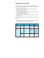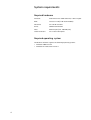
1
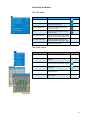
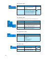
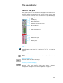
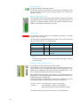
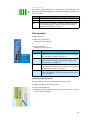
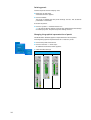
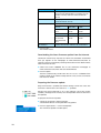
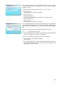
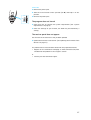
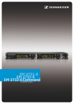
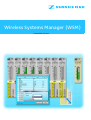
Wireless Systems Manager (WSM)
Instructions for use
Contents
Important information regarding this manual .................................. 2
For your safety ......................................................................................... 2
Included with delivery ............................................................................. 2
Capabilities of the WSM .......................................................................... 3
System requirements .............................................................................. 4
Required hardware .............................................................................................. 4
Required operating system ............................................................................... 4
Putting the system into operation ....................................................... 5
Connecting the NET 1 to a PC ............................................................................ 5
Installing the WSM software ............................................................................. 5
Configuring the network .................................................................................... 6
Launching the WSM PC software ...................................................................... 6
The Operator interface of WSM ............................................................. 7
Main window ........................................................................................................ 7
Overview of menus .............................................................................................. 9
The panel display .................................................................................. 11
Layout of the panel ........................................................................................... 11
Editing panels ..................................................................................................... 13
Updating the firmware of the devices .............................................. 17
“Easy Setup” frequency management ............................................. 21
Configuring devices .............................................................................. 24
If a problem occurs ............................................................................... 26
Hardware ............................................................................................................. 26
Software .............................................................................................................. 26
Glossary ................................................................................................... 28
You have made the correct selection!
These Sennheiser products will satisfy for years on the basis of their
reliability, economy and simple operation. Your guarantee is the good
name of Sennheiser and the competence it has gained in over 60 years of
manufacturing high-quality electroacoustic products.
Please take a few minutes to read this manual. We wish to help you enjoy
this technology quickly and easily.
1
Important information regarding this
manual
This manual describes the “Wireless Systems Manager” (WSM) PC
software for the NET 1 system.
Information on the NET 1 system as well as the transmitters and receivers
can be found in the individual user guides.
Note:
The operator interface for the WSM PC software is only available in
English.
For your safety
Individuals who are not trained in the operation of computers can
unintentionally alter computer files, corrupt or erase them! Ensure that
only competent individuals operate the computer on which the “WSM”
software is installed.
Save all files of your WSM on removable media (e.g. CD-ROM) as soon as
you have created or changed a configuration! Store the removable medium
securely in a safe location!
If you use a firewall, make sure to open port 8101 for incoming and
outgoing connections and port 2900 for outgoing connections.
Included with delivery
The following items are included:
y 1 “Wireless Systems Manager” (WSM) PC software on the CD
y 1 Installation instructions in the booklet accompanying the CD
y 1 Instructions as a PDF file on the CD
y 1 Online help on the CD
2
Capabilities of the WSM
The “Wireless Systems Manager” (WSM) permits real-time monitoring as
well as remote control of all relevant device parameters in the live mode.
Using the WSM PC software, you can:
y display and monitor the devices connected to the NET 1 system,
y configure the connected devices,
y perform a frequency preset scan,
y control 3000/5000 systems, combined systems and multichannel
systems with more than 20 channels,
y update the firmware of the NET 1,
y update the firmware of the receivers and transmitters via the NET 1
(except EM 3532).
The following Sennheiser systems can be configured using the WSM and
the NET 1:
Note:
Only transmitters and receivers that are equipped with the same
compander system can be combined with each other.
System
Compander
system
Receivers
Transmitters
Wireless
monitoring
system
ew IEM G2 HDX
portable:
rack-mount:
EK 300 IEM G2 SR 300 IEM G2
Wireless
microphone
system
ew G2
HDX
rack-mount:
EM 500 G2
EM 550 G2
EM 300 G2
portable:
SK 500 G2
SKM 5xx G2
SKP 500 G2
SK 300 G2
SKM 3xx G2
3000/
5000
series
HiDyn plus™
rack-mount:
EM 3532
portable:
SK 5212
SKM 5200
SKP 3000
3
System requirements
Required hardware
Processor:
Intel Pentium 4 or AMD Athlon XP, 2 GHz or higher
RAM:
at least 512 MB (1 GB recommended)
Hard drive:
min. 30 MB available
Drives:
CD-ROM or DVD-ROM
Ports:
Ethernet port (min. 100 MBit/sec)
Screen resolution:
min. 1280 x 1024 pixels
Required operating system
The WSM PC software supports the following operating systems:
y Windows 2000 with SP4
y Windows XP Professional with SP2
4
Putting the system into operation
Connecting the NET 1 to a PC
How to connect the NET 1 to a PC is shown in the user guide for the NET 1.
Installing the WSM software
Install the WSM PC software by following procedure below:
왘 Close all currently running programs, including those running in the
background (e. g. anti-virus programs).
왘 Place the WSM CD in the CD-ROM drive of your computer.
The installation wizard starts automatically and will guide you through
the installation.
Note:
If the wizard does not start automatically, use Explorer to change to the
CD drive containing the WSM CD and double-click on the “setup.exe”
file.
왘 Follow the wizard’s instructions.
The installation wizard suggests installation on the program folder on
the “C:\” drive as the subfolder “…\Sennheiser\WSM”. You can
change the install path by clicking on “Change directory”.
5
Configuring the network
To enable communication between the WSM and the NET 1, configure the
network (LAN connections) as follows:
Note:
Only launch the WSM after having configured the network.
Automatically obtaining an IP address (DHCP servers only)
왘 In the “Internet Protocol (TCP/IP) Properties” dialog box, click on the
“Obtain an IP address automatically” option button.
왘 Click on “OK”.
The dialog box closes. The configuration of the network is terminated.
Manually entering an IP address
If the “IP address” field is empty:
왘 In the “IP address” field, enter the following addresses:
IP address
Subnet mask
169.254.XXX.XXX
(XXX = any arbitrary number from 1 to 254)
255.255.0.0
왘 Click on “OK”.
The dialog box closes. The configuration of the network is terminated.
If the “IP address” field displays an IP address that does not start with
169.254. :
왘 Click on “Advanced...”
왘 In the “IP address” field, enter the following addresses:
IP address
Subnet mask
169.254.XXX.XXX
(XXX = any arbitrary number from 1 to 254)
255.255.0.0
왘 Click on “OK”. The IP address is added.
The dialog box closes. The configuration of the network is terminated.
Launching the WSM PC software
Note:
Before you launch the WSM software, you must switch on all rackmount devices and the NET 1.
To launch the WSM PC software:
왘 Double-click on the program icon on the desktop or click on “Start” >
“Programs” > “Wireless Systems Manager”.
This launches the WSM software and the main window appears.
6
The Operator interface of WSM
Main window
The main window contains the following regions:
쐃 Menu bar
쐇 Symbol bar (tool bar)
쐋 Display area
쐏 Status bar
Menu bar
The menu bar 쐃 is always visible.
You can select from the following menus (see page 9 and page 10):
y “File”
y “View”
y “System”
y “Channel”
y “Applications”
y “Help”
7
Symbol bar (tool bar)
You can operate the WSM via the menu bar 쐇 and via the buttons in the
symbol bar. The symbol bar can be shown or hidden (“View Menu” >
”Tool Bar”).
Display area
Scene
System window
Tab „Devices“
Tab „Messages“
Panel
With the standard settings, the display area 쐋 is divided in two. The
“panels” for the connected devices are displayed on the left; this region is
designated as the scene (“Master Scene”).
The tabs of the system window are displayed on the right.
In the scene (“Master Scene”), you can set up and move panels (see “The
panel display” on page 11).
The system window can be enlarged or reduced by dragging the border
between the scene and the system window. By selecting the menu item
“View” > “System Window”, you can show or hide the system window.
By clicking on the tabs, you can toggle between the tree structure of the
devices (“Devices”) and the message list (“Messages”).
Status bar
The last message from the devices is displayed on the left in the status
bar 쐏 .
The current date and time are displayed in the status bar on the right.
8
Overview of menus
The “File” menu
Menu item
Function of the menu item
Button
Open Configuration... Opens a saved configuration.
Save Configuration
Saves the current configuration
under the same name.
Save Configuration
As...
Saves the current configuration
under a new name.
Print
Prints the current configuration as
graphic or text.
Save Message Log...
Saves the messages in the system
window as a file (“Messages” tab).
Clear Message Log...
Deletes the messages from the
system window (“Messages” tab).
Exit
Terminates the “WSM”.
The “View” menu
Day Mode
Menu item
Function of the menu item
System Window
Shows or hides the system window.
Tool Bar
Shows or hides the symbol bar
(tool bar).
Night Mode
Changes to “Night Mode” display
or restores the “Day Mode” display.
Show Grid
Shows or hides the grid for aligning
the panels.
Snap to grid
Aligns the panels to the grid if you
move the panels.
Auto Arrange
Automatically arranges the panels
side by side.
Button
Night Mode
9
The “System” menu
Menu item
Function of the menu item
Remote Access
Activates access to the parameter
settings of the devices (see
page 24).
Refresh Device List
Updates (refreshes) the device list
in the system window (“Devices”
tab). New devices are displayed,
previously moved or deleted panels
are repositioned in the display
area.
Button
The “Channel” menu
The following menu items only appear if you have selected a panel.
Menu item
Function of the menu item
Properties
Displays the parameters of the selected device.
Delete
Deletes marked panels from the display area.
View Style
Displays a submenu with a selection list of three
different graphical representations for the
“receiver” panels (see page 14).
Icon
Displays a submenu with a selection list of
13 different icons (see page 15).
The “Applications” menu
Menu item
Function of the menu item
Frequency Manager
Calls up the “Frequency Management Wizard”.
Firmware Update
Starts the firmware update in the following order
(see page 17):
y NET 1
y Rack-mount devices
y Portable devices
The “Help” menu
10
Menu item
Function of the menu item
Help...
Opens a window in which the
online help is displayed.
About...
Opens a window in which the
version number is displayed.
Button
The panel display
Layout of the panel
Every panel displays a rack-mount device. The graphical representation of
the panel depends on the device type and the settings made under
“View Style” in the “Channel” menu. For details on the possible settings,
see “Editing panels” on page 13.
햲 Icon
햳 Port display
햴 Name of the device
햵 Frequency and channel display
햶 Diversity display
햷 Field strength display
햸 Status field
햹 Modulation display
햺 Battery status
Icon 햲
The upper left corner of the panel can be equipped with an icon
representing an instrument (see “Selecting an icon for a panel” on
page 15).
Port display 햳
This device is connected to the connection group 5 (“port”) of the first
NET 1.
Name of the device 햴
The name set on the device is displayed.
Frequency and channel display 햵
The frequency of the device appears below its name. The channel is
displayed below the frequency (see ““Easy Setup” frequency
management” on page 21 and “Configuring devices” on page 24).
11
Diversity display 햶
The active antenna is displayed in green.
The diversity sections of the EM 3532 twin receiver are labeled “A” and
“B”, the diversity sections of the “evolution wireless G2” receivers are
labeled “I” and “II”.
Field strength display (RF) 햷
The bar graphs indicate the current field strength. The horizontal yellow
line indicates the set squelch threshold (see “Configuring devices” on
page 24). If the field strength is below the squelch threshold, the bar
appears in red and the audio output is muted.
Status field 햸
If a threshold value on the device is exceeded or undershot, a message
appears in the status field.
The messages are highlighted in different colors. The part of the panel to
which the message refers is also highlighted.
Message
Color
Meaning of the message
MUTE
yellow
The device is muted.
PEAK
red
The device is overmodulated.
LOW BATT
red
The device’s battery is almost flat.
LOW RF
red
The squelch threshold is almost
reached.
Note:
The message also appears in the system window (“Messages” tab) and
in the status bar.
Modulation display (Deviation/AF) 햹
Level indicator for the audio level at the transmitter.
The threshold values are displayed in color in the modulation display. A
yellow section in the bar graph indicates that the transmitter is fully
modulated. An additional red section indicates overmodulation. If this
occurs, reduce the modulation level on the transmitter.
On a panel displaying an EM 3532 twin receiver, the modulation display is
labeled “Dev”, on panels displaying “evolution wireless G2” receivers, the
modulation display is labeled “AF”.
With these receivers, the modulation can be shown in different views (see
“Changing the graphical representation of panels” on page 14):
“Variant” 1 and 3: The modulation is shown as a bar graph.
“Variant” 2:
The modulation is shown as a colored box –
green for OK, yellow for high and red for overload.
The audio level of the rack-mount transmitters is also labeled “AF”.
12
Battery status 햺
The battery symbol indicates the charge status of the batteries. The
graphical representation depends on the device and battery type (primary
cells or accupack).
Color
Meaning
green
The battery is fully charged.
yellow
The battery is about half discharged.
red
The critical level is reached. The battery symbol flashes red
and a message appears in the panel, the system window
(“Messages” tab) and the status bar.
Editing panels
To edit the panels:
왘 Right-click on the panel.
A contextual menu appears.
or
왘 Click on “Channel”.
A contextual menu appears.
Menu item
Function of the menu item
Properties
Opens the “Properties” window in which you can set
various parameters in the selected device (see “Changing
the parameters of a device” on page 25).
Delete
Removes the selected panel from the display area. The
device continues to appear in the system window (see
“Deleting panels” on page 14).
View Style
Displays a submenu with a selection list of three different
display modes for the panels (see “Changing the graphical
representation of panels” on page 14).
Icon
Displays a submenu with a selection list of different icons
that can be added to a panel (see “Selecting an icon for a
panel” on page 15).
Enlarging/reducing panels
There is a dashed area in the lower right corner of the panel.
To steplessly reduce or enlarge the panels:
왘 Click on the dashed area.
왘 Hold down the mouse button and drag the panel to the left (= reduce)
or to the right (= enlarge).
13
Deleting panels
To remove panels from the display area:
왘 Right-click on the panel.
A contextual menu appears.
왘 Click on “Delete”.
The panel is deleted and the panel settings are lost. The set device
parameters are retained.
To restore all panels:
왘 Click on “System” > “Refresh Device List”.
All rack-mount devices appear as panels with the default panel settings
on the display area. The previous panel settings are lost.
Changing the graphical representation of panels
The WSM offers different graphical representations for the panels.
To change the graphical representation for a “receiver” panel:
왘 Click on the panel of the device.
왘 Click on “Channel” > “View Style”.
An additional contextual menu appears.
왘 Select the desired style:
Receivers
Variant 1
14
Variant 2
Variant 3
Note:
The graphical representation for a “transmitter” panel depends on the
device settings.
Transmitters
Mode:
Stereo
Mode:
Mono
Selecting an icon for a panel
You can assign an icon representing an instrument to each panel.
왘 Click on the desired panel.
왘 Click on “Channel” > “Icon”.
An additional contextual menu appears.
왘 Select one of the following icons:
Icon Designation
“Trumpet“
“Guitar“
“Vocal“
“Bass“
“Accordion“
“Flute“
“Clarinet“
“Saxophone“
“Percussion“
“Trombone“
“Violin“
“No Icon“
The icon then appears in the upper left corner of the selected panel.
15
Aligning and moving panels
To align panels to the grid:
왘 Click on “View” > “Show Grid” to show the grid.
A tick appears in front of the menu item. The grid is shown.
왘 Click on the panel and hold down the mouse button.
왘 Drag the panel to the desired position in the scene.
If the menu item “Snap to Grid” is activated, the panel is automatically
aligned to the grid.
To automatically arranging panels:
왘 Click on “View” > “Auto Arrange”.
A tick appears in front of the menu item. The panels are arranged side
by side.
16
Updating the firmware of the devices
NET 1 is compatible with previously delivered wireless systems (see table
on page 3). However, these systems must have a compatible firmware.
You can identify receivers and transmitters that already have this
firmware via the additional menu item “Software Revision” or “SW REV”
in the operating menu of the device or the identifying mark “NET” on the
type plate of the device.
The current firmware is included on the CD. You can also download the
latest firmware updates from the Sennheiser homepage at
www.sennheiser.com/net1.
Displaying the firmware versions of the devices
왘 In the system window, click on the “Devices” tab.
왘 If necessary, place the portable device in front of the infrared interface
of the NET 1.
왘 In the system window, right-click on “NET 1”.
A contextual menu appears.
왘 Click on “Show device information”.
The “NET1 version Information” window opens.
17
Display
Meaning
“NET1 software“
The entry “Application” shows the firmware
version of the selected NET 1. The other version
numbers are only relevant to the Sennheiser
Service.
“NET1 hardware“
The displayed version numbers are only relevant
to the Sennheiser Service.
“Subdevices“
Displays the connected devices as follows:
“Port 4“
“EM550G2“ “2.0.0“
Channel 4 on the Rack-mount Firmware
NET 1
device
version
“IR Port“
“EK300G2“
Device in front of Portable
device
the infrared
interface of the
NET 1
“IP Address“
“1.7.3“
Firmware
version
Displays the network address (IP) of the NET 1.
왘 Click on “OK”.
The window closes.
Downloading the latest firmware update from the Internet
Sennheiser continuously improves the WSM. We therefore recommend
that you register on our homepage at www.sennheiser.com/net1 to
regularly receive a newsletter providing information on the WSM and the
latest firmware versions.
왘 Select the current SENNPKG file on the Sennheiser homepage at
www.sennheiser.com/net1 and start the download.
왘 Click on “Open”.
The file is automatically saved in the “New Releases” subfolder of the
program folder. If this folder already contains a file, this file is moved to
the “Archive” folder.
Preparing the firmware update
Only the firmware is updated, the device settings remain the same. The
firmware in the EM 3532 twin receiver is not updated.
Devices that are marked with a “U” in the “Devices” tab of the system
window (see diagram on the left) have incompatible firmware that must
be updated.
To prepare the firmware update:
왘 Switch on all receivers and transmitters.
Switched-off devices will be ignored during update.
왘 Click on “Applications” > “Firmware Update”.
The “Firmware Update” window opens.
18
If there is a new firmware version available in the “New Releases” folder
of the program folder, it is displayed in the “The selected firmware
package is:” field.
To use the firmware version from the “New Releases” folder:
왘 Click on “Next >”.
The connection to the devices is checked.
왘 Click on “Choose...”.
A dialog box appears.
왘 Select the desired SENNPKG file and confirm by clicking on “OK”.
The dialog box closes.
왘 Click on “Next >”.
The connection to the devices is checked.
The “Connected Devices” window on the left displays the connected NET 1
and the corresponding devices. The “Firmware Package” window on the
right displays all available firmware versions from the selected SENNPKG
file.
Devices with an older firmware version are automatically ticked.
To not update the firmware in a device:
왘 In the “Connected Devices” window, click on the checkbox of the device.
The tick is removed. The firmware is not updated.
If you want to transmit an older firmware version to a device:
왘 Click on the “Allow downgrade” checkbox.
A tick appears.
왘 In the “Connected Devices” window, click on the checkbox of the device.
A tick appears. The older firmware version will be transmitted to the
devices during firmware update.
19
Updating the firmware in the devices
The firmware is automatically updated in the following order:
1. NET 1
2. Rack-mount devices
3. Portable devices
CAUTION!
Risk of data loss if transmission is interrupted during
firmware update!
Data may be lost if the transmission is interrupted. The
devices may also be damaged as a result.
왘 When updating the firmware, do not interrupt any
device connection to the NET 1 or to the rack-mount
devices.
왘 Do not disconnect power from the devices. Preferably
use fully charged batteries for the portable devices!
왘 Since the updating process takes about 40 seconds,
firmly position the portable devices in front of the
infrared interface.
왘 Place the portable devices in front of the infrared
interface of the NET 1 until a corresponding message
appears in the wizard window.
To start the firmware update:
왘 Click on “Start”.
왘 Follow the instructions of the wizard.
Note:
After the firmware in the NET 1 has been updated, the device restarts.
This can take up to one minute.
20
“Easy Setup” frequency management
Using the “Easy Setup” frequency management capability, you can:
y distribute frequencies in the channel bank to devices from the
“evolution wireless G2” series that are connected to the NET 1,
y detect occupied frequencies,
y allocate unused frequencies to the devices.
You can also configure devices after “Easy Setup” (see “Configuring
devices” on page 24).
Launching the “Easy Setup” frequency management
왘 Click on “Applications” > “Frequency Manager”.
The “Frequency Management Wizard” window opens.
왘 Activate the “Easy Setup” option button and click on “Next >”.
왘 Follow the instructions of the wizard.
“Easy Setup” with or without frequency preset scan
You can allocate unused frequencies in various ways:
y “Preset Scan...” - after a frequency preset scan:
To find occupied as well as unused frequencies in the current vicinity of
the system, perform a frequency preset scan.
y “Continue without Scan” - without a frequency preset scan:
To allocate to rack-mount devices already known unused frequencies,
specify these frequencies without a scan.
You can then allocate these unused frequencies to the portable devices.
21
Performing a frequency preset scan for monitoring systems
Note:
The rack-mount transmitters of the corresponding frequency range are
automatically switched off during the frequency preset scan.
Performing a frequency preset scan for an EK 300 IEM G2
The frequency preset scan is performed using the EK 300 IEM G2 portable
receiver. The scan results are then transmitted to the NET 1. The WSM
retrieves the data from the NET 1.
왘 Before starting the scan, switch all portable transmitters of your system
off, since frequencies used by switched-on transmitters will not be
displayed as “unused”.
왘 Start the frequency preset scan on the EK 300 IEM G2 (see
ew 300 IEM G2 user manual).
Transfering the unused frequencies of the receiver to the NET 1
왘 When prompted by the wizard, place the receiver in front of the infrared
interface of the NET 1. The distance between the infrared interface of
the NET 1 and the infrared interface of the receiver must not exceed
10 cm.
Note:
< 10 cm
Strong extraneous light may interfere with the transfer of the
frequencies via the infrared interface. Therefore, position the receiver
so that any possible interference caused by extraneous light is avoided.
The arrow in the diagram on the left indicates the direction from which
the IR radiation must impinge upon the receiver.
The WSM continuously retrieves the scan results from the NET 1.
y When all frequencies are successfully transmitted, a tick appears in the
WSM window and the “Next >” button becomes active.
y When the transmission has failed (e.g. because the receiver operates in
the wrong frequency range), repeat the procedure.
Allocating frequencies to rack-mount transmitters
You can allocate frequencies automatically or manually.
y Automatic allocation:
If you have connected more transmitters (IEM) from one frequency
range than free channels are available in one channel bank, the RF
signals of the surplus transmitters are muted.
y Manual allocation:
If you assign the same frequency to several transmitters (IEM), only the
first transmitter with this frequency is transmitting. The RF signals of
the surplus transmitters are muted.
22
Allocating frequencies for a monitoring system without a
frequency preset scan
Note:
When you allocate frequencies without a frequency preset scan,
interference with transmitters in the vicinity of the system may result.
Allocating frequencies to rack-mount transmitters
You can allocate frequencies automatically or manually.
y Automatic allocation:
If you have connected more transmitters (IEM) from one frequency
range than free channels are available in one channel bank, the RF
signals of the surplus transmitters are muted.
y Manual allocation:
If you assign the same frequency to several transmitters (IEM), only the
first transmitter with this frequency is transmitting. The RF signals of
the surplus transmitters are muted.
Performing a frequency preset scan for microphone systems
When you have connected both monitoring and microphone systems to
the NET 1, you first have to perform the frequency preset scan for the
monitoring system.
The frequency preset scan is always performed for all frequencies in the
selected channel bank.
For receivers from the “evolution wireless G2” series, the frequencies are
arranged in banks and stored in the receivers. For EM 3532 twin receivers,
the frequencies are selected from tables that are supplied together with
the WSM software. As for “evolution wireless G2” receivers, these tables
are arranged in banks.
Allocating frequencies to rack-mount receivers
You can allocate frequencies automatically or manually.
y Automatic allocation:
If you have connected more receivers from one frequency range than
free channels are available in one channel bank, the WSM reassigns the
last frequency assigned several times.
y Manual allocation:
You can assign the same frequency to several receivers.
23
Allocating frequencies for a microphone system without a
frequency preset scan
Note:
When you allocate frequencies without a frequency preset scan, interference with transmitters in the vicinity of the system may result.
Allocating frequencies to rack-mount receivers
You can allocate frequencies automatically or manually.
y Automatic allocation:
If you have connected more receivers from one frequency range than
free channels are available in one channel bank, the WSM re-assigns
the last frequency assigned several times.
y Manual allocation:
You can assign the same frequency to several receivers.
Configuring devices
You can configure the devices using the “Properties” window.
Before you can change parameters, you must activate the “Remote
Active” menu item:
왘 Click on “System” > “Remote Access”.
A tick appears in front of the menu item.
When you call up the “Properties” window (see next section), “Remote
Active” is displayed in the lower part of the window.
Displaying an overview of parameters
To display the parameters of a device:
왘 Double-click on a device In the system window (“Devices” tab) or on the
corresponding panel in the display area.
The “Properties” window opens.
“Properties” window of a
wireless microphone system
“Properties” window of a
wireless monitoring system
The parameters for the device appear In the left column (“Name”). To the
right, the associated values (“Value”) and units (“Units”).
24
Changing the parameters of a device
The parameters that you can change depend on the respective device type.
Specific information on the parameters can be found in the user manuals
for the devices.
Line highlighted in
Meaning
white
y You can change these parameters.
y The data transmission to the devices was
successful.
yellow
The parameter has been changed but not yet
transmitted to the devices.
blue
You have clicked on a parameter highlighted in
white.
왘 Click on the corresponding parameter.
The line for the parameter is highlighted in blue.
왘 Click on “Set”.
A new window opens.
왘 Enter the desired value.
왘 Confirm with “OK”.
The window closes; the new parameter is displayed.
왘 Then transmit the parameters as described in the user manual of the
NET 1.
Note:
The frequency of the device can only be changed when the channel
bank “U” is selected.
25
If a problem occurs
Hardware
First check the connections and cables for the devices (see NET 1 user
manual).
Software
The Sennheiser homepage at www.sennheiser.com/net1 has an FAQ
(Frequently Asked Questions) area. Recurring problems and possible
solutions will be listed here.
The firmware update has failed
(displays of the devices remain dark)
Start the updating process as described in the section “Updating the
firmware in the devices” on page 20.
Put the device manually into the update mode (see below) and then
position it again in front of the infrared interface.
ew G2 rack-mount devices
왘 Disconnect the device from the mains by pulling out the mains plug (the
device remains connected to the NET 1 via the RJ 10 cable).
왘 Keep the “ON/OFF” button pressed.
왘 Reconnect the mains plug.
ew G2 portable devices and SKP 3000
왘 Keep the “ESC” button (portable receivers) or the “ON/OFF” button
(portable transmitters) pressed.
왘 Briefly interrupt the power supply by pushing the batteries/accupack
against the contact spring in the battery compartment.
SK 5212
왘 Remove the battery.
DOWN
26
SET
왘 Slide the multi-function switch to the right (UP 왘 ) and keep it in this
position.
UP
왘 Reinsert the battery.
SKM 5200
왘 Remove the power pack.
왘 Slide the multi-function switch upwards (UP 왖 ) and keep it in this
position.
UP
왘 Reinsert the power pack.
SET
DOWN
The program does not launch
왘 Check that your PC satisfies the system requirements (see “System
requirements” on page 4).
왘 Check the settings of your firewall; the WSM may be blocked by a
setting.
The receiver panel does not appear
The firmware in the receiver has not yet been updated.
왘 Update the firmware in the receiver (see “Updating the firmware of the
devices” on page 17).
If a problem occurs that cannot be solved with the proposed solutions:
y Register on the Sennheiser homepage at www.sennheiser.com/net1
and describe the problem in the “Support” section
or
y contact your local Sennheiser agent.
27
Glossary
Deviation
Modulation associated with the receiver;
Represented as a bar diagram (Dev)
Easy Setup
Function for allocating frequencies
Firmware
Software that resides on a chip in the device.
It can and, sometimes, must be updated.
The current firmware is supplied on the CD.
In the future, new versions will be available from the Sennheiser home
page.
Frequency preset scan
Function for detecting (identifying) unused and occupied frequencies in
the immediate vicinity; the identified frequencies can be allocated to the
receivers manually or automatically.
Panel
Window in the display area; the panels contain, among other information,
the name of the device, the current frequency and the field strength
display.
Squelch
Squelch is the term used to describe the suppression of interfering noises
during transmission.
Scene
Left portion of the display area containing the panels for the devices.
28
Sennheiser electronic GmbH & Co. KG
30900 Wedemark, Germany
Phone +49 (5130) 600 0
Fax +49 (5130) 600 300
www.sennheiser.com
Printed in Germany
Publ. 03/07
516555/A3