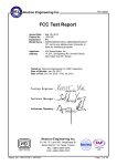
1
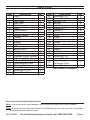
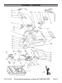
3 in 1 JUMPSTARTER/
AIR COMPRESSOR
39954
Set up And Operating Instructions
Visit our website at: http://www.harborfreight.com
Read this material before using this product.
Failure to do so can result in serious injury.
Save this manual.
Copyright© 1999 by Harbor Freight Tools®. All rights reserved. No portion of this manual or any artwork
contained herein may be reproduced in any shape or form without the express written consent of
Harbor Freight Tools. Diagrams within this manual may not be drawn proportionally. Due to continuing
improvements, actual product may differ slightly from the product described herein. Tools required for
assembly and service may not be included.
For technical questions or replacement parts, please call 1-800-444-3353.
Manual Revised 06d, 08j , 09d
Specifications
Battery Type
Power Output
Cables
Compressor
Output Socket
Features
Sealed, lead-acid, rechargeable, 17 Ah
12 VDC, 900 amps peak; 400 amps starting power
Rubber insulated (#4) copper; 400 amp clamps
260 PSI maximum pressure
12 VDC Cigarette lighter output
• Overload protection
• Automatic charge cutoff (at 14.5~15.5 volts) to help
prevent overcharging
• Inflating Needle and Air Raft Tips
Note: Performance of this unit may vary depending on variations in local line voltage.
Save This Manual
You will need the manual for the safety warnings and precautions, assembly instructions,
operating and maintenance procedures, parts list and diagram. Keep your invoice with this
manual. Write the invoice number on the inside of the front cover. Keep the manual and
invoice in a safe and dry place for future reference.
Safety Warnings and Precautions
WARNING: When using tool, basic safety precautions should always be followed to reduce
the risk of personal injury and damage to equipment.
Read all instructions before using this tool!
1. Wear eye protection. When working on or around lead-acid batteries, always wear
ANSI-approved eye protection.
2. Avoid contact with Battery Acid. If splashed, immediately wash effected area with
clean water. Continue washing area until medical help arrives.
3. Connect cables to proper polarities. Connect RED POSITIVE (+) cable to Positive
Battery Terminal first. Connect BLACK NEGATIVE (-) cable to body ground (a non moving
metal part) second. Do not connect the BLACK NEGATIVE (-) cable to the Negative
Battery Terminal. Turn vehicle ignition off before making cable connections.
4. Use this tool in well ventilated areas. Do not attempt to jump start vehicle around
flammable gases or liquids.
5. Do not allow the Black and Red clamps to touch. If this happens it can melt clamps
or other metal objects. Place them only on the corresponding terminals.
6. 12 Volt Systems Only. Use only with vehicles and boats with 12 volt electrical systems.
7. For emergency use only. Do not use this system in the place of a vehicle battery. Only
use to jump start your vehicle.
8. Avoid working alone. If an accident happens, an assistant can bring help.
REV 08b, 08k
SKU 39954
For technical questions, please call 1-800-444-3353.
Page 2
9. Avoid electrical shock. Use extreme caution when clamping around uninsulated conductors or bus bars. Prevent body contact with grounded surfaces such as pipes, radiators,
ranges, and cabinet enclosures when testing voltages.
10. Keep work area clean. Cluttered areas invite injuries.
11. Avoid damaging Jumpstarter System. Use only as specified in this manual.
12. Observe work area conditions. Do not use tool in damp or wet locations. Don’t expose
to rain. Keep work area well lighted.
13. Keep children away. Children must never be allowed in the work area. Do not let them
handle machines, tools, or extension cords.
14. Store idle equipment. When not in use, tools must be stored in a dry location to inhibit
rust. Always lock up tools and keep out of reach of children.
15. Do not place this unit in direct sunlight, direct heat or moisture.
16. Dress properly. Do not wear loose clothing or jewelry as they can be caught in moving
parts. Protective, electrically nonconductive clothes and nonskid footwear are recommended when working. Wear restrictive hair covering to contain long hair.
17. Use eye and ear protection. Always wear ANSI-approved impact safety goggles.
18. Do not overreach. Keep proper footing and balance at all times. Do not reach over or
across electrical cables or frames.
19. Maintain tools with care. Inspect tool cords periodically and, if damaged, have them
repaired by an authorized technician.
20. Stay alert. Watch what you are doing, use common sense. Do not operate any tool
when you are tired.
21. Check for damaged parts. Before using any tool, any part that appears damaged
should be carefully checked to determine that it will operate properly and perform its
intended function. Check for alignment and binding of moving parts; any broken parts
or mounting fixtures; and any other condition that may affect proper operation. Any part
that is damaged should be properly repaired or replaced by a qualified technician. Do
not use the tool if any switch does not turn On and Off properly.
22. Replacement parts and accessories. When servicing, use only identical replacement
parts. Use of any other parts will void the warranty. Only use accessories intended for
use with this tool. Approved accessories are available from Harbor Freight Tools.
23. Do not operate tool if under the influence of alcohol or drugs. Read warning labels
on prescriptions to determine if your judgment or reflexes are impaired while taking drugs.
If there is any doubt, do not operate the tool.
24. People with pacemakers should consult their physician(s) before use. Electromagnetic fields in close proximity to heart pacemaker could cause pacemaker interference
or pacemaker failure.
25. The warnings, cautions, and instructions discussed in this instruction manual cannot
cover all possible conditions and situations that may occur. It must be understood by
the operator that common sense and caution are factors which cannot be built into this
product, but must be supplied by the operator.
SKU 39954
For technical questions, please call 1-800-444-3353.
Page 3
Operation
Warning: Electrical shock can cause death or injury. Avoid touching exposed conductors of electricity.
Recharger Socket
Safety Switch
Volt Meter (17)
Light Case (2)
Cigarette Lighter
Socket (18)
Button (15)
AC Inlet
Power Cord (47)
Cigarette Lighter
Recharger (18)
Button Lock (16)
Copper Booster
Cables (11)
The Jumpstarter System is designed for use with vehicles and boats. You will not
need a host vehicle or 120 VAC power supply. You can also use this system as a portable
power source of 12 VDC in remote areas or emergencies.
Jump Starting
1. Switch the Safety Switch to the OFF position.
2. Connect RED POSITIVE (+) cable to Positive Battery Terminal first. Connect BLACK
NEGATIVE (-) cable to body ground (a non moving metal part) second. Do not connect the BLACK NEGATIVE (-) cable to the Negative Battery Terminal. Turn vehicle
ignition off before making cable connections.
3. Switch the vehicle or boat ignition to the On position, and turn the Safety Switch to the
ON position.
4. Wait for about a minute or two.
5. Switch the boat or vehicle to the start position for no more than 5 to 6 seconds.
6. If the vehicle or boat engine does not start, wait at least 3 minutes before retrying.
Caution: Never allow the red and black clamps to touch each other or a common conductor.
REV 05h, 07h, 08b
SKU 39954
For technical questions, please call 1-800-444-3353.
Page 4
7. When the engine is running, turn the Safety Switch to the OFF position, disconnect the
black clamp first, and return the cable to its stored position on the jumpstarter system.
8. Disconnect the red clamp and return the cable to its position on the system.
9. As soon as possible, recharge the 3 in 1 Jump Start / Air Compressor.
Using the 12 V Receptacle
1. Lift up the cover of the Cigarette Lighter Receptacle (18)
2. Insert the cigarette lighter Plug from the appliance into the Cigarette Lighter Receptacle (18).
Compressor Operation
Switch, Compressor (43)
Pressure Meter
Hose Compartment
Inflation Needle and Plastic
Adapters (37)
Hose Connector
1. Turn the main Power Switch on the front panel to the On position.
2. If inflating a tire, place the Hose Connector on the tire valve stem and press the connector lever down to lock in place.
3. If inflating a ball, air mattress, or other item, place the inflation needle or plastic
adapter into the hose connector and press the connector lever down to lock in place.
Insert the adapter into the item to be inflated.
4. Turn the compressor power Switch (43) to the On position.
Note: Do not overinflate item. Check pressure gauge. Only run the Compressor for 10
minutes at a time. If more air is needed, wait 10 minutes before using again.
5. Turn Switch Off when inflation is finished.
REV 08b
SKU 39954
For technical questions, please call 1-800-444-3353.
Page 5
Maintenance
1. After every use, wipe unit with clean dry cloth and turn all switches to the off position.
Store in a cool, dry place out of reach of children.
2. If light does not work, make sure it is tight in the socket. If it does not work after tightening, replace the bulb.
3. Recharge unit after every use, and after every 3 months of storage.
Recharging
This unit is rechargeable, by either the Power Cord, or by use of a vehicle 12 VDC
cigarette lighter output socket. It is recommended that the battery is kept fully charged at
all times. If the battery is left in a low charge state it could shorten battery life. The time
required to recharge the battery depends on the number of previous battery jump starts.
To check and see if the battery is low, press the (red) Button (16). The Meter (17) will
show the battery charge level. Green area of meter indicates that it is charged.
To charge and recharge using the Power Cord and AC Inlet:
1. Insert the Power Cord’s female plug into the rectangular AC Input on the side of the
unit, and the male plug into a 120 VAC outlet.
2. For the initial charge and for recharges, allow the Jump Start System to
recharge for 48 hours (maximum). Check the recharge progress by pressing the
red Button (15). This will show the level of battery power on the Volt Meter (17).
Note: If the Volt Meter does not show any voltage, verify the voltage with a separate
voltage meter (not included).
3. This Jumpstarter System is equipped with an automatic cut off to help prevent
overcharging.
To recharge using a 12 VDC supply:
1. Insert the Cigarette Lighter Recharger Plug into the Front Panel port labeled
Recharge.
2. Insert the other end of the Cigarette Lighter
Recharger Cord into the 12 VAC Cigarette lighter
receptacle on your vehicle or boat.
3. Allow the Jump Start System to recharge for 8 to 10
hours. An automatic cut off will help prevent overcharging the battery.
Battery Replacement
1. Remove all 8 Screws (27), using a Phillips screwdriver, from the back Cover (5) to
expose the Battery (20).
2. Remove the 2 Phillips Screws (24) that are holding the Battery Bracket (12) to the
Battery.
REV 09d, 09j
SKU 39954
For technical questions, please call 1-800-444-3353.
Page 6
3. Lift the Battery (20) out of the compartment.
4. Detach the jumper cables and the recharging wires from the battery terminals. Make
sure that red and black jumper cables stay with their recharging wires and are not
switched.
5. Remove the dead battery.
6. Attach the jumper cables and recharging wires to the terminals of the new battery; red
cable to positive terminal, black cable to negative terminal. Make sure that the battery
has the label facing out from the back of the Jump Start System.
7. Place the new battery into the System, taking care not to damage the Circuit Board
(7).
8. Reattach the Battery Bracket (12) with the 2 Phillips head Screws (24).
9. At this time you may also replace the fuses in the fuse box, by removing the failed
fuse and replacing with a new fuse.
10. Attach the battery Cover (5) using the 8 Phillips head screws (27).
11. Recharge new battery using the 12 volt Adapter (22) for at least 4 hours.
Battery Disposal
After the battery in the Jumpstarter System has expired, it should be recycled.
Some States require this recycling. Contact your local solid waste authority for recycling
information.
Warning: Do not dispose of battery by fire. This could result in an explosion. Before disposing of battery, cover exposed terminals with heavy duty electrical tape to prevent
shorting. Do not expose battery to intense heat or fire as this could cause an explosion.
PLEASE READ THE FOLLOWING CAREFULLY
The manufacturer and/or distributor has provided the parts list and assembly diagram in this manual as a reference tool only. Neither the manufacturer or distributor makes any representation or warranty of any kind to the buyer that he or she is qualified to make any
repairs to the product, or that he or she is qualified to replace any
parts of the product. In fact, the manufacturer and/or distributor
expressly states that all repairs and parts replacements should be undertaken by certified and licensed technicians, and not by the buyer. The buyer assumes all risk and liability arising out of his or her repairs to the original product or replacement parts thereto, or arising out of his or her installation of replacement parts thereto.
SKU 39954
For technical questions, please call 1-800-444-3353.
Page 7
Parts List
Item
1
2
3
4
5
6
7
8
9
10
11
12
13
14
15
16
17
18
19
20
21
23
24
25
26
Description
Qty
Case
1
Light Case
1
Light Glass
1
Light Cup
1
Back Cover
1
Label
1
Circuit Board
1
Clip
1
Adapter Holder
1
Washer
1
Copper Booster Cables
2
Bracket
2
Light Socket
1
Bulb
1
Button (Lock)
1
Button
1
Volt Meter
1
Cigarette Lighter Socket
1
Cigarette Lighter Cup
1
Battery 12V / 17 AH
1
Overcharging Cutoff
1
Adapter Cover
1
Screw M2.5 x 6
2
Screw M2.5 x 12F
2
Screw M3 x 12
4
Item
27
28
29
30
31
32
33
34
35
36
37
38
39
40
41
42
43
44
45
Description
Qty
Screw M4 x 16
8
Screw M3 x 12
4
Bolt M5 x 16
2
Nut M5
2
Nut M3
2
Washer 2.5
2
Washer 3
2
Washer 3
1
Cover
1
Clamp
1
Inflation Needle
1
Clamp
1
Pressure Meter Cover
1
Clip
2
Gasket
1
Air Pump Unit
1
Switch
1
Screw M3 x 16
7
Screw ST3 x 12
1
Cigarette Lighter
46
1
Recharger Cord*
47 Power Cord
1
*Not shown on diagram.
Record Product’s Serial Number Here:
Note: If product has no serial number, record month and year of purchase instead.
Note: Some parts are listed and shown for illustration purposes only, and are not available
individually as replacement parts.
SKU 39954
For technical questions, please call 1-800-444-3353.
Page 8
SKU 39954
5
47
44
27
42
40
37
38
33
39
35
30 29 20 24 12
44
41
36
43
26
6
31 34 21 25 32 7 10
1
19
4
18
11
9
8 26
2
3
13
14
17
15
16
28 23
45
Assembly Diagram
For technical questions, please call 1-800-444-3353.
Page 9
LIMITED 90 DAY WARRANTY
Harbor Freight Tools Co. makes every effort to assure that its products meet high
quality and durability standards, and warrants to the original purchaser that this product
is free from defects in materials and workmanship for the period of 90 days from the date
of purchase. This warranty does not apply to damage due directly or indirectly, to misuse,
abuse, negligence or accidents, repairs or alterations outside our facilities, criminal activity,
improper installation, normal wear and tear, or to lack of maintenance. We shall in no event
be liable for death, injuries to persons or property, or for incidental, contingent, special
or consequential damages arising from the use of our product. Some states do not allow
the exclusion or limitation of incidental or consequential damages, so the above limitation
of exclusion may not apply to you. This warranty is expressly in lieu of all other warranties, express or implied, including the warranties of merchantability and fitness.
To take advantage of this warranty, the product or part must be returned to us with
transportation charges prepaid. Proof of purchase date and an explanation of the complaint must accompany the merchandise. If our inspection verifies the defect, we will either
repair or replace the product at our election or we may elect to refund the purchase price
if we cannot readily and quickly provide you with a replacement. We will return repaired
products at our expense, but if we determine there is no defect, or that the defect resulted
from causes not within the scope of our warranty, then you must bear the cost of returning
the product.
This warranty gives you specific legal rights and you may also have other rights
which vary from state to state.
3491 Mission Oaks Blvd. • PO Box 6009 • Camarillo, CA 93011 • (800) 444-3353
SKU 39954
For technical questions, please call 1-800-444-3353.
Page 10