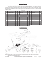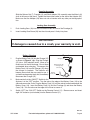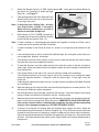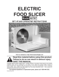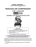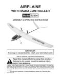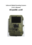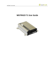
1
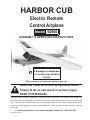
harbor cub
Electric Remote
Control Airplane
Model 92906
assembly & Operating Instructions
IMPORTANT:
If damage is caused due
to a crash, your warranty
is void.
Visit our website at: http://www.harborfreight.com
Read this material before using this product.
Failure to do so can result in serious injury.
Save this manual.
Copyright© 2005 by Harbor Freight Tools®. All rights reserved. No portion of this manual or any artwork contained herein may be reproduced in any shape or form without the express written consent of Harbor Freight
Tools. Diagrams within this manual may not be drawn proportionally. Due to continuing improvements, actual
product may differ slightly from the product described herein. Tools required for assembly and service may not
be included.
For technical questions or replacement parts, please call 1-800-444-3353.
Revised Manual 09k
THANK YOU for choosing a HARBOR FREIGHT TOOLS product. For future reference, please
complete the owner’s record below:
Model______________
Serial No._____________ Purchase Date_______________
SAVE THE RECEIPT, WARRANTY AND THESE INSTRUCTIONS. It is important that you read the
entire manual to become familiar with the unit BEFORE you begin assembly.
Technical Specifications
Wingspan������������������������������ 371/2”
Wing Area����������������������������� 212.3 sq. in.
Fuselage Length������������������� 283/4”
Flying Weight������������������������ 18.1 oz.
Battery���������������������������������� 8.4V, 600 mAh, NiMh
Flight Time���������������������������� About 10 minutes
Remote Control��������������������� 3 Channel
Remote Power���������������������� 8 “AA” Batteries (Not included)
Safety Warnings and Precautions
WARNING: When using product, basic safety precautions should always be followed to
reduce the risk of personal injury and damage to equipment.
Read all instructions before using this product!
1.
Store idle equipment. When not in use, the Airplane must be stored in a dry location to inhibit
damage from moisture and salt air.
2.
Check for damaged parts. Before using the Airplane, any part that appears damaged should
be carefully checked to determine that it will operate properly and perform its intended function.
Check for any broken or damaged parts and any other conditions that may affect its operation.
Replace or repair damaged or worn parts immediately. Do not use the Airplane if any part is
damaged or broken.
3.
Replacement parts and accessories. When servicing, use only identical replacement parts.
Use of any other parts will void the warranty.
4.
For ages 16 and over. Do not let children use the Airplane without adult supervision.
Failure to do so could result in personal injury and/or property damage.
5.
Keep your work area clean and well lit. Cluttered benches and dark areas invite accidents.
6.
Always check hardware and assembled parts after assembling. All connections should
be tight and hardware tightened.
Rev 09j
SKU 92906
For technical questions, please call 1-800-444-3353.
Page 2
7.
Dress properly. Wear restrictive hair covering to contain long hair.
8.
Use eye protection. Always wear ANSI approved impact safety goggles when assembling
and using this product.
9.
Use the right Airplane and components. There are certain applications for which this Airplane was designed. Do not modify this Airplane and do not use this Airplane for a purpose
for which it was not intended.
10.
Do not use or assemble the Airplane if under the influence of alcohol or drugs. Read
warning labels on prescriptions to determine if your judgement or reflexes are impaired while
taking drugs. If there is any doubt, do not assemble or use the Airplane.
11.
Do not pick up the Airplane while it is in motion.
12.
Use only Batteries of the type recommended.
13.
Do not mix old and new batteries.
14.
Remove batteries if the Airplane is not used for a long period of time.
15.
Make certain to use the Airplane in a large area free from interference from trees, electrical power lines and other obstacles. If two airplanes with the same frequency are used
(both with the same numbers on the transmitter and/or receiver) they must be at least
1640 feet away from one another.
16.
Never fly near buildings, cars or busy streets.
17.
Do not fly the Airplane at or near other people or animals.
18.
Keep this product away from small children; small parts can be easily swallowed.
WARNING: The warnings, cautions, and instructions discussed in this instruction manual cannot
cover all possible conditions and situations that may occur. It must be understood by
the operator that common sense and caution are factors which cannot be built into this
product, but must be supplied by the operator.
Unpacking
When unpacking your Airplane with Radio Controller, check to make sure the parts listed on the
next page are included. If any parts are missing or broken, please call HARBOR FREIGHT TOOLS
at 1-800-444-3353.
Please read the following carefully
THE MANUFACTURER AND/OR DISTRIBUTOR HAS PROVIDED THE PARTS DIAGRAM IN THIS
MANUAL AS A REFERENCE TOOL ONLY. NEITHER THE MANUFACTURER NOR DISTRIBUTOR MAKES ANY
REPRESENTATION OR WARRANTY OF ANY KIND TO THE BUYER THAT HE OR SHE IS QUALIFIED TO MAKE
ANY REPAIRS TO THE PRODUCT OR THAT HE OR SHE IS QUALIFIED TO REPLACE ANY PARTS OF THE
PRODUCT. IN FACT, THE MANUFACTURER AND/OR DISTRIBUTOR EXPRESSLY STATES THAT ALL REPAIRS
AND PARTS REPLACEMENTS SHOULD BE UNDERTAKEN BY CERTIFIED AND LICENSED TECHNICIANS
AND NOT BY THE BUYER. THE BUYER ASSUMES ALL RISK AND LIABILITY ARISING OUT OF HIS OR HER
REPAIRS TO THE ORIGINAL PRODUCT OR REPLACEMENT PARTS THERETO, OR ARISING OUT OF HIS OR
HER INSTALLATION OF REPLACEMENT PARTS THERETO.
REV 05j
SKU 92906
For technical questions, please call 1-800-444-3353.
Page 3
Assembly/ Operation
Your Airplane with Radio Controller will require complete assembly. It is important that you
read the entire manual to become familiar with the product BEFORE you use the Airplane. Before
assembling the Airplane be sure that you have all parts described in the Parts List and Assembly
Diagram, below.
Parts List
Part
Description
Q’ty Part
Description
Q’ty
Part
Description
Q’ty
1
Main Wing Assembly
1
8
Motor Cover
1
18
Wing Screw
6
1a
Left Wing
1
9
Propeller
2*
19
Battery Cover
1
1b
Right Wing
1
20
1” Screw
2
1c
Top Wing Support
1
10
Landing Gear
1
21
Vertical Stabilizer
1
1d
Bottom Wing Support
1
11
Remote Control
1
22
Tail Screw
3
2
Horizontal Stabilizer
1
12
Receiver
1
23
Strut Screw
2
3
Fuselage
1
13
Servo
2
24
Shaft Adapter
1
4
Pushrod
2
14
Battery Pack
1
25
Motor Cover Screw
2
5
Wing Strut
2
15
Charger
1
26
Landing Gear Brace
1
6
380 Motor
1
16
Speed Controller
1
27
Ribbon
1
7
Spinner Nut
1
17
Crystals (pair)
1
*Includes 1 spare
Assembly Diagram
NOTE:Some parts are listed and shown for illustration purposes only, and are not available
individually as replacement parts.
REV 08j
SKU 92906
For technical questions, please call 1-800-444-3353.
Page 4
Set out all parts on a clear and level surface prior to assembly.
Wing Assembly
1.
Position the Left and Right Wings (1a,1b) inside the Bottom Wing Support (1d) as shown in
Figure 1.
2.
Align the Top Wing Support (1c) in top of the Bottom Support and fasten the wing assembly
together using the six Wing Screws (18).
3.
The Wing Assembly (1) should balance on a flat surface with about 2” to 23/8” distance from
the wing tips to the table. The height of both sides should be roughly equal.
4.
Insert the two tabs at the back of the Bottom Wing Support (1d) into the holes on the top of the
Fuselage (3). Gently press the front of the Wing Assembly (1) into place. Secure with the two
1” Screws (20).
5.
Hook a Wing Strut (5) into the tabs underneath one Wing - see Figure 2. Make sure that the
tab at the other end of the Strut (5) is angled properly to fit into the bottom of the Fuselage
(3). Attach the strut to the bottom of the Fuselage (3) using a Strut Screw (23). Repeat for the
other Strut and Wing.
Figure 1
Left
Wing (1a)
Bottom
Wing
Support
(1d)
Figure 2
Wing
Strut (5)
Left/Right
Wing (1a/1b)
Right
Wing (1b)
Tail Assembly
1.
2.
Use the remaining Tail Screw (22) to attach the
Vertical Stabilizer (21) onto the tab on the end
of the Fuselage (3) - see Figure 3.
3.
Connect the clips on both Pushrods (4) to the
tabs controlling the rudder and elevators.
4.
Figure 3
Use two Tail Screws (22) to attach the Horizontal Stabilizer (2) onto the end of the Fuselage
(3).
With Servos energized adjust the clips on the
pushrods, until both the elevators and rudder
are straight and level.
SKU 92906
Vertical
Stabilizer
(21)
Tail
Screw (22)
For technical questions, please call 1-800-444-3353.
REV 08j
Page 5
Propeller Assembly
Slide the Spinner Nut (7), Propeller (9), and Shaft Adapter (24) assembly onto the Motor’s (6)
shaft at the nose of the plane. Tighten the internal hex screw on the side of the Adapter (24).
Make sure that the Adapter (24) does not rub or interfere with any other part during operation.
Landing Gear Assembly
1.
Push Landing Gear (10) into the slot located under the front of the Fuselage (3).
2.
Insert Landing Gear Brace (26) into the slot and press it firmly into place.
IMPORTANT:
If damage is caused due to a crash, your warranty is void.
Battery Charging
1.
Plug the Battery Pack (14) into the Charger (15)
as shown in Figure 4, right. Plug the Charger
(15) into a 120V electrical outlet. Allow up to
three hours for the initial charge. Do not leave
unattended when charging. Disconnect the
Battery Pack (14) from the Charger (15) when
the charge is complete. The batteries will
become warm when they are ready for use. If
you feel them becoming overly hot, immediately
disconnect the Charger (15).
Figure 4
Charger (15)
Battery Pack (14)
to Charger (15)
connection
Battery
Pack (14)
2.
Make certain that the “On/Off” Switch for the
Airplane is in the “OFF” position. Turn the tabs at the edge of the Battery Cover (19) to the
side and remove the Cover. Plug the Battery Pack (14) into the socket located underneath the
Battery Cover (19). Insert the Battery Pack (14) into the Fuselage (3) and close the Battery
Cover (19). Turn the tabs over the edge of the Cover to secure it.
3.
Switch “OFF” the “ON/ OFF” Switch on the Remote Control (11). Remove cover and insert
eight “AA” batteries (not included) into the Remote Control (11).
REV 06e
SKU 92906
For technical questions, please call 1-800-444-3353.
Page 6
Remote
Control (11)
Figure 6
Figure 5
Ribbon
(27)
Battery
indicator
light
Elevator
control
Rudder
control
Elevator
trim
Rudder
trim
Reverse
toggles
Back of Remote
Control (11)
Figure 7
Elevator Controls
Plane Speed
control
“On/Off”
trim
adjustment
control
stick
Setting up The Controls
1.
Tie the Ribbon (27) to the end of the antenna, as shown in Figure 5.
2.
Make certain that your hands are clear of the Propellers and any moving parts. Push the Plane
Speed control all the way toward the L position - see Figure 6. Move both trim adjustments
to the center. Turn on the switch on the Airplane and the switch on the Remote Control (11).
3.
If the plane is adjusted properly, the rudder (on the Vertical Stabilizer (21) and elevators (on
the Horizontal Stabilizer (2)) should be straight and level.
4.
If either the Rudder or Elevators are not straight and level, the Clips at the end of the Pushrods
(4) should be adjusted. This is done by turning the Clip IN (to shorten) or OUT (to lengthen)
the Pushrod. Note: This should be done with Servos energized (power to Radio & Plane ON)
for proper alignment.
5.
Each control stick on the front of the control has a trim adjustment next to it, shown in Figure 5.
These adjustments are used to fine-tune the position of the controls. They are typically used
in flight to ensure that the plane can stay at a steady height and can fly straight more easily.
6.
NOTE: The Plane Speed control is disabled until the Safety Button on the side of the
Fuselage (3) is pressed. Leave it disabled until you are ready to fly the plane.
Pushing the plane speed control (see Figure 6) upward, toward the H position, will cause the
Propeller (9) to spin faster. Pushing the plane speed control back down, toward the L position,
will slow down and stop the Propeller (9).
7.
The rudder control stick controls the plane’s left and right direction. Move the control stick right
to turn the rudder right, turning the plane right; and left to turn the rudder left, turning the plane
left. When the control stick is in the center position, the rudder should also be centered.
8.
The Elevator Control Stick changes the position of the Elevator which causes the Plane to climb
or descend. Moving the Stick up causes the Elevator to more down making it possible for the
Plane to descend; moving the Stick down causes the Elvator to move up making it possible for
the Plane to climb. If the Stick is centered the Elevator should be level.
9.
Practice these steps until you are comfortable with the controls.
10.
The reverse toggles can be used to reverse the operation of the two front control sticks. Each
reverse toggle controls the Control Stick nearest it. There are two settings: “N”=Normal
Operation; “R”=Reversed Controls (left->right or forward->backward, and vice-versa).
Flying the Airplane
1.
Choose a day when the wind is light. The Ribbon (27) attached to the Remote Control antenna
should be blowing slightly (not greater than 30 degrees) and not be blowing straight out. Find
a wide-open field.
REV 08j
SKU 92906
For technical questions, please call 1-800-444-3353.
Page 7
2.
Switch the Remote Control (11) “ON” and the plane “ON”. Lastly, press the Safety Button on
the side of the Fuselage (3) under the Right
Figure 8
Wing (1b) - see Figure 8.
3.
Face the Airplane into the wind. Move the Plane
Speed Control all the way up so that the motor
is running at full power.
Note: If launching from a Rolling Take - off make
sure Plane taxies straight, if not adjust
Wheel Wires by bending one or both to
achieve a controlled straight taxi.
4.
Right
Wing (1b)
Safety
Button
ON/OFF
Switch
Fuselage
(3)
With Airplane at FULL POWER and taxiing in
a straight line pull back on the Elevator Control
to gain altitude and achieve Take - off.
Note: If Hand Lauching it is recommended two people work together to launch the Plane, one to
Launch and one to operate the Radio Transmitter.
5.
If Hand Launching tilt the Plane up about 10°, propel in a straight line and release into the
wind.
6.
Let the Airplane climb to and fly at about 50 to 300 feet high. By moving the control sticks you
can change pitch, direction, and speed.
7.
If the Airplane rises too slowly, or dives, you may wish to adjust the elevator trim until the plane
flies level with no pressure applied to the stick.
8.
To steer the Airplane, move the rudder control stick to the left to steer to the left, and right to
steer it right. Move the rudder control stick slightly to adjust for minor changes in direction and
tilt of the Airplane.
9.
If the airplane drifts to the right or left, you may adjust the rudder trim accordingly.
If the Airplane continues to fly too far right or too far left, correct for it by moving the rudder
control the opposite direction. If flying left, move the control right. If flying right, move the
control left.
If adjusting the rudder control does not work, land the Airplane and adjust the Rudder Pushrod
(4) to compensate.
10.
Note that letting go of the control sticks will automatically bring them to a center position. This
will cause the Airplane to glide, unpowered.
11.
Normal flight time for one full charge is about ten (10) minutes. If the plane appears to be losing
power or climbs with difficulty, the batteries are low. Land the plane.
12.
When the remote control’s battery begins to reach the end of its power, the red indicator light will
blink or it will make a warning noise. When this occurs, IMMEDIATELY LAND THE AIRPLANE.
If the remote control’s battery is allowed to die completely, the plane will be uncontrolled
and may cause damage to property or SEVERE PERSONAL INJURY.
13.
To bring in the Airplane for landing, glide the Airplane down against the wind. Move the
plane speed control backwards to slow the Propeller (9). Pull the Elevator control stick back
somewhat to pull the nose of the plane up. Move the rudder control stick to adjust for direction.
Continue to gradually decrease the Propeller (9) speed until you bring it to a stop and land the
Airplane. If airplane descends too quickly, press slightly harder on the plane speed control to
compensate.
REV 08j
SKU 92906
For technical questions, please call 1-800-444-3353.
Page 8