1
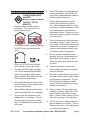
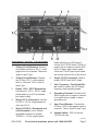
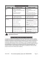
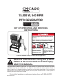
15,000 W, 540 RPM
PTO Generator
65309
Set up, Operating, and Servicing
Instructions
Using an engine indoors CAN KILL YOU IN
MINUTES.
Engine exhaust contains carbon monoxide.
This is a poison you cannot see or smell.
NEVER use inside
a home or garage,
EVEN IF doors and
windows are open.
Only use OUTSIDE
and far away from
windows, doors, and
vents.
Visit our website at: http://www.harborfreight.com
Read this material before using this product.
Failure to do so can result in serious injury.
Save this manual.
Copyright© 2008 by Harbor Freight Tools®. All rights reserved. No portion of this manual or any artwork
contained herein may be reproduced in any shape or form without the express written consent of
Harbor Freight Tools. Diagrams within this manual may not be drawn proportionally. Due to continuing
improvements, actual product may differ slightly from the product described herein. Tools required for
assembly and service may not be included.
For technical questions or replacement parts, please call 1-800-444-3353.
Revised Manual 09k
Save This Manual
NOTICE is used to
address practices
not related to personal injury.
Keep this manual for the safety warnings and precautions, assembly, operating, inspection, maintenance and cleaning
procedures. Write the product’s serial
number in the back of the manual near the
assembly diagram (or month and year of
purchase if product has no number). Keep
this manual and the receipt in a safe and
dry place for future reference.
CAUTION, without
the safety alert
symbol, is used to address
practices not related to
personal injury.
WARNING! Read all instructions.
Failure to follow all instructions
listed below may result in fire,
serious injury and/or DEATH.
The warnings and precautions
discussed in this manual cannot
cover all possible conditions and
situations that may occur. It must
be understood by the operator that
common sense and caution are
factors which cannot be built into
this product, but must be supplied
by the operator.
Important SAFETY
Information
In this manual, on the labeling,
and all other information
provided with this product:
This is the safety alert
symbol. It is used to alert
you to potential personal
injury hazards. Obey all
safety messages that
follow this symbol to avoid
possible injury or death.
DANGER indicates
a hazardous
situation which, if not
avoided, will result in death or
serious injury.
WARNING
indicates a
hazardous situation which, if
not avoided, could result in
death or serious injury.
SAVE THESE INSTRUCTIONS
Set up precautions
1.
Follow precautions and instructions
provided by tractor manufacturer.
2.
Gasoline fuel and fumes are flammable, and potentially explosive. Use
proper fuel storage and handling procedures. Do not store fuel or other
flammable materials nearby. Use only
in a well-ventilated area.
3.
Have multiple ABC class fire extinguishers nearby.
4.
Set up and use only on a flat, level,
surface that is capable of supporting
this Generator, the tractor and the
forces applied during use of this tool.
CAUTION, used
with the safety
alert symbol, indicates a
hazardous situation which, if
not avoided, could result in
minor or moderate injury.
SKU 65309
For technical questions, please call 1-800-444-3353.
Page 2
5.
Wear ANSI-approved safety goggles,
heavy-duty work gloves, and dust
mask/respirator during set up.
6.
Use only lubricants and fuel recommended in the engine manual provided by the tractor manufacturer.
7.
Permanent wiring or wiring into an
existing electrical service MUST be
done by a licensed electrician, and
MUST comply with all applicable
codes.
• Don’t connect the generator directly
to a building’s wiring. A portable
electric generator that is connected
directly to utility line can ‘back feed’
into the power lines. This lower voltage created by the generator can
be increased to thousands of volts
by line transformers. That unexpected voltage can injure or even
kill a utility lineman making outage
repairs many miles away. Hard
wiring can also cause expensive
damage to utility equipment and the
generator.
9.
Don’t overload the generator. The
total wattage used by the devices
should be less than the output rating
of the generator. If you put too many
devices on the generator, it could
seriously damage them. Overloading the generator can also cause
fire. This generator is rated at 15,000
Watts. NOTE: At start-up, devices
draw more power in a surge than
they do during continuous operation.
When figuring total wattage of all
devices connected to this generator,
use the higher start-up rating of each
device.
10. Do not exceed the current limit specified for any one receptacle. Refer to
the Specifications chart for amperage
limits on each receptacle.
• A hard wired generator must be
installed by a licensed electrician
with a UL approved cut-off switch
that will automatically disconnect
the home from the power grid when
the generator is being used. Check
with the local utility company before
having a generator hard-wired to a
building.
8.
Make sure the generator is properly
grounded to avoid electrical shocks.
Connect a 6 ga. or larger insulated
copper wire to the Ground Connection on the Control Panel. Connect this wire to a suitable external
ground, such as a metal stake in the
ground.
SKU 65309
For technical questions, please call 1-800-444-3353.
Page 3
Operating precautions
1.
Carbon Monoxide
Hazard
Using an engine indoors
CAN KILL YOU IN
MINUTES.
Engine exhaust contains carbon
monoxide. This is a poison you
cannot see or smell.
6.
Wear ANSI-approved safety glasses,
hearing protection, and NIOSH-approved dust mask/respirator under a
full face shield during use.
7.
People with pacemakers should
consult their physician(s) before
use. Electromagnetic fields in close
proximity to a heart pacemaker could
cause pacemaker interference or
pacemaker failure. Caution is necessary when near the engine’s magneto
or recoil starter.
8.
Use only accessories that are recommended by Harbor Freight Tools for
your model. Accessories that may be
suitable for one piece of equipment
may become hazardous when used
on another piece of equipment.
9.
Do not operate in explosive atmospheres, such as in the presence of
flammable liquids, gases, or dust.
Electrical sparks may ignite the dust
or fumes.
NEVER use inside a home or garage,
EVEN IF doors and windows are
open.
Only use OUTSIDE and far away
from windows, doors, and vents.
2.
The exposed PTO shaft is dangerous. Do not operate the generator
without the guards in place and in
good condition. Stay away from the
PTO shaft during operation.
3.
Drive shaft Guards must be in place
and not spinning. Drive shaft must be
secured at both ends.
4.
Keep children away from the equipment, especially while it is operating.
5.
Do not leave the equipment unattended when it is running. Turn off
the equipment (and remove safety
keys, if available) before leaving the
work area.
SKU 65309
10. Keep the generator, tractor, and
surrounding area clean and clear of
debris at all times.
11. Stay alert, watch what you are doing
and use common sense when operating this piece of equipment. Do not
use this piece of equipment while
tired or under the influence of drugs,
alcohol or medication.
12. Dress properly. Do not wear loose
clothing or jewelry. Keep hair, clothing and gloves away from moving
parts. Loose clothes, jewelry or long
hair can be caught in moving parts.
13. Do not overreach. Keep proper footing and balance at all times. This enables better control of the equipment
in unexpected situations.
For technical questions, please call 1-800-444-3353.
Page 4
14. Do not cover the engine or generator
during operation.
indicate it is acceptable for outdoor
use.
15. Do not handle any electrical device
while standing in water, while barefoot, or while hands or feet are wet.
ELECTRICAL SHOCK WILL RESULT.
6.
Make sure the extension cord is properly wired and in good electrical condition. Always replace a damaged
extension cord or have it repaired by
a qualified electrician before using it.
16. Excessively high drive speeds are
dangerous. This unit was designed
for the PTO shaft to turn at 540 RPM.
Do not operate the Generator at excessively high speeds.
7.
Protect the extension cords from
sharp objects, excessive heat, and
damp or wet areas.
3.
When using more than one extension cord to make up the total length,
make sure each cord contains at
least the minimum wire size required.
(See Table A.)
4.
If you are using one extension cord
for more than one tool, add the
nameplate amperes and use the sum
to determine the required minimum
cord size. (See Table A.)
5.
If you are using an extension cord
outdoors, make sure it is marked with
the suffix “W-A” (“W” in Canada) to
SKU 65309
(at full load)
100’
150’
The smaller the gauge number of the
wire, the greater the capacity of the
cord. For example, a 14 gauge cord
can carry a higher current than a 16
gauge cord. (See Table A.)
EXTENSION CORD
LENGTH
75’
2.
As the distance from the supply outlet
increases, you must use a heavier
gauge extension cord. Using extension cords with inadequately sized
wire causes a serious drop in voltage,
resulting in loss of power and possible tool damage. (See Table A.)
NAMEPLATE
AMPERES
50’
1.
(120/240 VOLT)
25’
Extension Cords
RECOMMENDED MINIMUM WIRE
GAUGE FOR EXTENSION CORDS*
0 – 2.0
18
18
18
18
16
2.1 – 3.4
18
18
18
16
14
3.5 – 5.0
18
18
16
14
12
5.1 – 7.0
18
16
14
12
12
7.1 – 12.0
18
14
12
10
-
12.1 – 16.0
14
12
10
-
-
16.1 – 20.0
12
10
-
-
-
TABLE A
* Based on limiting the line
voltage drop to five volts at
150% of the rated amperes.
For technical questions, please call 1-800-444-3353.
Page 5
Service precautions
1.
Wear ANSI-approved safety goggles
during set up and maintenance.
2.
Turn tractor switch off and remove
key after use.
3.
Unconditioned electrical power can
damage sensitive equipment. Use a
line conditioner (sold separately) between this generator and the devices.
4.
Maintain labels and nameplates on
the equipment. These carry important information. If unreadable or
missing, contact Harbor Freight Tools
for a replacement.
5.
Store equipment out of the reach of
children.
Save these
instructions.
SKU 65309
For technical questions, please call 1-800-444-3353.
Page 6
loads requiring up to 50 Amps of
current up to 12,000 Watts (12kW) of
power. Use a connector rated to 250
Volts, 50 Amps with a same-rated
4-wire set. The 50 Amp circuit breakers protect each hot line of the circuit.
Control Panel Features
1.
20 Amp Circuit Breakers. Each circuit breaker protects a 125 V~ outlet
against short or overload. These are
“push to reset” type.
2.
30 Amp Circuit Breaker. Protects
the 30 Amp 125 V~ outlet against
short or overload. This is “push to
reset” type.
3.
4.
5.
6.
Single 12V DC receptacle. Used to
power 12VDC loads at 8.3 Amps.
7.
Volt / Frequency / Time Digital Meter. Used to monitor the AC voltage,
frequency and operating speed.
8.
Single 125 V~ Receptacle. Use this
for 125 V~, 60 Hz, single phase devices up to 30 A.
Grounding Terminal. Connect to #6
AWG copper wire or larger to connect
to an earth-driven copper or brass
grounding rod.
9.
Single 125/250 V~ Receptacle and
circuit breakers. Use a 4-blade
grounded connector to operate
125/250 V~, 60 Hz, single phase
Amp Circuit Breaker. Protects the
8.3 Amp 12 DC outlet against short or
overload. This is “push to reset” type.
10. Voltage Switch. 240V on the left,
120V on the right.
Duplex 125 V~ GFCI Receptacles.
Use these for 125 V~, 60 Hz, single
phase loads up to 20 A (combined
per duplex outlet).
REV 09d
SKU 65309
For technical questions, please call 1-800-444-3353.
Page 7
16,000 Watts
To prevent
serious injury
from accidental
starting:
Turn the Power Switch of the
equipment to its “OFF”
position, wait for the engine to
cool, and disable the engine
before assembling or making
any adjustments to the
equipment
1 (single) phase
Basic Specifications
PTO Operating
Speed
540 RPM
PTO Power
At Least 25 HP
Output Shaft
1-3/8” diameter shaft with
6-tooth spline
Rated
Continuous
Output
Rated Maximum
Output
15,000 Watts
Phase
To prevent
serious injury
from Electrical Shock:
A licensed electrician must do
all installation work, including
earth-ground connection.
• 12 VDC, 8 A, 2-prong outlet
• 2 X 125 V~, 20 A, duplex
GFCI outlets (5-20R)
Receptacles
• 125 V~, 30 A 3-blade twist
lock outlet (L5-30R)
• 125/250 V~, 50 A 4-prong
outlet (14-50R)
Unpacking
When unpacking, check to make sure
that the item is intact and undamaged. If
any parts are missing or broken, please
call Harbor Freight Tools at the number
shown on the cover of this manual as soon
as possible.
Keep this generator and all
electrical wires, cords and
components dry.
Note: For additional information regarding
the parts listed in the following pages,
refer to the Assembly Diagram near
the end of this manual.
Included components:
a.Generator unit
b.PTO shaft
c. PTO guard
Set Up Instructions
Read the entire Important
Safety Information
section at the beginning of this
manual including all text under
subheadings therein before set
up or use of this product.
SKU 65309
1.
Attach the PTO (power Take-Off)
Shield to the Generator using the
supplied bolts and washers. Adjust and tighten securely, as shown
above.
For technical questions, please call 1-800-444-3353.
Page 8
2.
The PTO shaft must be attached to
the tractor (not included) and the
Generator. The ends of the PTO shaft
slide into the Generator Gearbox, and
the tractor PTO drive.
3.
WARNING! The PTO shaft must
fit properly into the PTO drive. Do not
attempt to use this generator if the
PTO shaft does not fit properly. Severe injury or property damage may
result if the Drive shaft comes loose
during operation.
4.
When installing the PTO shaft, ensure that it is aligned as (seen from
above) with both the Generator and
the tractor. Also keep the vertical
difference of the Generator and
tractor as small as possible to minimize the angle of the Drive shaft
U-joints.
Note: Aligning the shafts minimizes torsional forces which tend to topple the
Generator. Minimizing vertical angles
reduces friction, heat and wear on the
U-joints of the PTO shaft.
SKU 65309
5.
Attach the generator to the tractor using all 3 connection points and appropriate hardware (not included). The
connection method must prevent the
generator from twisting during operation.
6.
The Generator must be on a solid,
level surface that is capable of supporting its weight and the forces applied during use.
7.
Check the Gearbox oil level (see
maintenance section of this manual).
8.
Before operating the Generator, it
must be grounded. Grounding Terminals are provided on the Control
Panel and on the Rear Vent panel of
the Generator. Use #6 AWG copper
wire or larger to connect to an earthdriven copper or brass grounding rod.
Do not operate the Generator without
grounding.
For technical questions, please call 1-800-444-3353.
Page 9
Operating Instructions
Read the entire Important
Safety Information
section at the beginning of this
manual including all text under
subheadings therein before set
up or use of this product.
6.
Test each GFCI outlet by pressing the
TEST button. The green light on that
outlet should go out. Then press the
RESET button. The green light on
that outlet should come back on. If
either GFCI outlet does not function
as described have a qualified electrician repair the generator before use.
Inspect Generator and
7. With the devices turned OFF, plug the
equipment looking for
devices into the appropriate outlets.
damaged, loose, and missing
CAUTION! Do not plug in or unplug
parts before set up and starting.
electrical loads while the loads are
If any problems are found, do
turned on.
not use equipment until fixed
properly.
8. Turn on the devices one at a time
from the largest to the smallest.
Start Procedure
Check the frequency meter reading
on the Control Panel. If the reading
Before starting the engine:
has dropped below 60 Hz, do not
a.Follow the Set Up Instrucconnect any additional loads.
tions to prepare the equipment. Follow all instructions 9. Be sure that all devices are in good
in the separate tractor manworking order before connecting
ual.
them to the generator. If a device
b.Inspect the generator and
begins to operate abnormally, betractor.
comes sluggish, or stops suddenly,
turn off the device. Then disconnect
c. Fill the tractor engine with
the device and examine it for signs of
the proper amount and type
malfunction.
of fuel and oil.
1.
Set the tractor on a flat surface. Set
the brake on the tractor. Ensure that
it is not in gear, and cannot move during operation.
2.
Unplug all loads from the Generator
before starting to prevent permanent
damage to connected devices.
3.
Start and operate the tractor according to the provided engine manual.
4.
Engage the tractor PTO drive.
5.
Set the tractor’s PTO speed to 540
RPM.
SKU 65309
Note: If an overloaded circuit causes the
AC circuit breaker to switch off, reduce the electrical load on the circuit
and wait a few minutes before resetting the circuit breaker.
10. The DC terminal may be used operating 12 VDC portable devices only.
WARNING: Do not use this generator
to charge 12 VDC batteries without a
charge controller. Directly charging a
12 Volt battery may cause the battery
to overheat and possibly explode.
For technical questions, please call 1-800-444-3353.
Page 10
CAUTION: Do not attempt to start an automobile engine with this generator.
Voltage feedback from the running
automobile may damage the generator.
Note: The DC terminal may be used while
the AC power is in use. An overloaded DC circuit will trip the DC circuit
protector (push button comes out).
If this happens, wait a few minutes
before pushing in the circuit protector
to resume operation.
11. Watch the Volt Meter to determine
the current load on the generator.
If the Volt Meter reading falls below
110 V~ (or the voltage requirement
of attached devices), remove some
devices from the system to reduce
demand on the generator.
WARNING! To prevent serious
injury from electric shock:
Use the GFCI unit properly.
If the power supply to either duplex
outlet is interrupted, there may be a
short in the attached device’s wiring
that is tripping the GFCI unit. Check
all wiring connections carefully for
moisture and damaged insulation
before pressing the reset button.
If the GFCI unit trips again
immediately or after a short while,
discontinue use immediately and
have the generator and the device
attached to that outlet serviced by
a qualified electrician.
Stopping the Generator
1.
Turn OFF all attached devices.
2.
Unplug the cords from the Generator.
3.
Turn OFF the tractor engine.
SKU 65309
For technical questions, please call 1-800-444-3353.
Page 11
shields and guards are in good condition. Inspect for general condition and
cleanliness.
erator.
Servicing
To prevent
serious injury
2. Keep the generator clean and free of
from accidental
dirt, grease or debris. Clean it regustarting:
larly and whenever it becomes dirty.
Turn the Power Switch of the
Use a soft brush, damp soft cloth or
equipment to its “OFF”
low pressure air to remove dirt and
position, wait for the engine to
debris.
cool, and disable the engine
before assembling or making
CAUTION: Do not use high pressure
any adjustments to the
water spray to clean the generator.
equipment
Injected water can damage the genTo prevent
serious injury
from equipment failure:
Do not use damaged
equipment. If abnormal noise,
vibration, or excess heating
occurs, have the problem
corrected before further use.
Maintenance Procedures
Many maintenance procedures,
including those not detailed
in this manual, will need to
be performed by a qualified
technician for safety. If you
have any doubts about your
ability to safely service the
equipment, have a qualified
technician service the
equipment instead.
3.
Protect the generator from high humidity and salt air environments.
4.
Periodically clean the interior of the
Generator Control Panel. Use compressed air, a dry brush or electrical
contact cleaner to remove carbon
build up and metal corrosion.
5.
When cleaning, check for loose wires
or damage. Be sure printed circuit
boards are firmly plugged into their
sockets.
Gearbox Oil Check
1.
Check the oil level before each use
and after each 10 hours of use. To
check oil level, be sure generator is
as level as possible.
Note: These procedures are in addition to
the regular checks and maintenance
explained as part of the regular operation of the engine and equipment.
1.
Perform regular visual inspection of
the Generator and PTO shaft. Look
for loose or broken wires or defective
connections. Check for missing, corroded or loose fasteners. Be sure all
SKU 65309
For technical questions, please call 1-800-444-3353.
Page 12
Gearbox
Oil Fill
Plug (31)
Oil Level
Plug (30)
Gearbox
Oil Drain
Plug (21)
2.
3.
The oil should be visible at least halfway up the Oil Level Plug (30).
If necessary, remove the Gearbox Oil
Fill Plug (31) and add SAE 90 oil to
fill to the recommended level. Replace the Oil Fill Plug.
5.
After all the used oil has drained,
replace and tighten the Oil Drain Plug
(21).
6.
Slowly add SAE 90W Oil until the
oil is visible at least halfway up the
Gearbox Oil Sight (30).
7.
Replace the Oil Fill Plug (31) and
tighten securely.
8.
Recheck all plugs for tightness. Restart the Generator and check for
leaks.
Lubricating the PTO shaft
1.
The PTO shaft must be lubricated
frequently.
2.
Use a low pressure grease gun to
inject lithium grease into the grease
fittings. The grease fittings are located at both ends of the PTO shaft
Universal Joint Bearings (13).
3.
Also apply Lithium grease to the
Splines and telescoping parts of the
Shaft.
Changing Gearbox Oil
1.
After the first 25 hours of operation,
you must change the Gearbox oil.
You must also change the oil after
every 250 hours of operation, or each
6 months, whichever comes first.
2.
To change the oil, operate the generator for approximately 30 minutes
to warm the oil in the Gearbox (22).
Then shut down the tractor and generator.
3.
Immediately after shutting down,
while the oil is still warm, remove the
Oil Drain Plug (21) along with the Oil
Fill Plug (31) to help the oil to drain.
4.
Catch the draining oil in a suitable
container. Dispose of the used oil
properly.
REV 09j
SKU 65309
For technical questions, please call 1-800-444-3353.
Page 13
Storage
1.
Wait for generator to cool, then remove from the tractor.
2.
Clean equipment with clean dry cloth.
3.
Check and top off Gearbox oil level.
4.
Lubricate PTO shaft as explained
previously.
5.
Apply a thin coat of rust preventive oil
to all uncoated metal parts.
6.
Cover and store in a dry, well-ventilated area out of reach of children.
7.
For cold weather operation, store the
equipment in a cool dry area to prevent
condensation and premature wear.
SKU 65309
For technical questions, please call 1-800-444-3353.
Page 14
Equipment Troubleshooting
Problem
Possible Causes
Probable Solutions
No output or low
output
1. Open or shorted rotor.
2. Open or shorted stator.
3. Generator operating below correct
speed.
4. Generator overloaded.
5. Short circuit in load.
1. Replace rotor.
2. Replace stator.
3. Operate generator at correct
speed.
4. Reduce load to rated output.
5. Disconnect load. Check voltage at
all receptacles. Repair short.
Output voltage is too
high.
1. Incorrect Adjustable Voltage
Regulator (AVR) setting.
2. Engine speed is too high.
1. Readjust Adjustable Voltage
Regulator (AVR) setting.
2. Reduce engine speed.
Generator is
overheating.
1. Generator is overloaded.
2. Rotor is rubbing stator.
1. Reduce load.
2. Check bearings (23 and 27). Repair
or replace as needed.
3. Ensure generator air vents are
clear.
4. Check stator, repair or replace as
needed.
5. Repair or replace rotor.
3. Poor ventilation.
4. Short circuit in stator.
5. Shorted turns in rotor.
Sparking at brushes.
1. Generator is overloaded.
2. Brushes not seated properly.
3. Brushes sticking in holder.
4. Brushes worn to less than 3/8”.
1. Reduce load.
2. Contour and re-seat brushes.
3. Remove brushes, clean holder and
reinstall brushes.
4. Replace brushes. NOTE: Replace
brushes in pairs.
Follow all safety precautions whenever diagnosing or servicing the
equipment or generator.
PLEASE READ THE FOLLOWING CAREFULLY
The manufacturer and/or distributor has provided the parts list and assembly
diagram in this manual as a reference tool only. Neither the manufacturer or
distributor makes any representation or warranty of any kind to the buyer that
he or she is qualified to make any repairs to the product, or that he or she is
qualified to replace any parts of the product. In fact, the manufacturer and/
or distributor expressly states that all repairs and parts replacements should
be undertaken by certified and licensed technicians, and not by the buyer. The
buyer assumes all risk and liability arising out of his or her repairs to the
original product or replacement parts thereto, or arising out of his or her
installation of replacement parts thereto.
SKU 65309
For technical questions, please call 1-800-444-3353.
Page 15
PARTS LIST
Part
Description
Q’ty
Part
PARTS LIST
Description
Q’ty
1
Frame
1
32
Control Panel Frame
1
2
Connecting Plate
2
33
Control Panel Window
1
3
Nut m12
4
34
Control Panel Gasket
1
4
Washer m12
4
35
GFCI Receptacle
2
5
Bolt m12 x 75
4
36
Meter
1
6
Pin m22
2
37
Locking 125V Socket
1
7
Washer m22
2
38
250 V Socket
1
8
Locknut m22
2
39
Circuit Breaker 50A
2
9
Drive Shaft
1
40
Circuit Breaker 30A
1
10
Shield Plate
1
41
T Receptacle
1
11
Shield Plate Cover
1
42
Circuit Breaker 20A
2
12
U-Joint
2
43
Gate Pin
1
13
Universal Joint Bearing
2
44
Hinge
1
14
Gimbal Arm
1
45
Control Box Cover
1
15
Gimbal Pipe
1
46
Washer m72
1
Adjustable Voltage Regulator
(AVR)
1
16
17
Seal m30 x 72 x 10
1
47
Bolt m8 x 12
5
18
Sealed Bearing 6207-2Z
1
48
Control Box Body
1
19
Center Drive Gear
1
49
Bolt m10 x 60
4
20
Sealed Bearing 6206-2Z
1
50
Rubber Shock Absorber
4
21
Gearbox Oil Drain Plug m16 x 1.5
1
51
Control Box Bracket
2
22
Gearbox Body
1
52
Wire
1
23
Sealed Bearing 6305-2Z
1
53
Washer m12
4
24
Seal m35 x 72 x 8
1
54
Bolt m12 x 180
4
25
Washer m72
1
55
15 KW Alternator
1
26
Output Shaft
1
56
m60 x 40 x 25 Shock Absorber
4
27
Sealed Bearing 6306-2Z
1
57
Bolt m12 x 60
4
28
Gasket
1
58
Alternator Rear Cover
1
29
Gearbox Cover Plate
1
59
Stator & Rotor
1
30
Oil Level Plug
1
60
Alternator Front Cover
1
31
Gearbox Oil Fill Plug
1
REV 09d; 09j
SKU 65309
For technical questions, please call 1-800-444-3353.
Page 16
ASSEMBLY DIAGRAM
SKU 65309
For technical questions, please call 1-800-444-3353.
Page 17
Wiring Diagram
SKU 65309
For technical questions, please call 1-800-444-3353.
Page 18
Limited 1 year / 90 Day warranty
Harbor Freight Tools Co. makes every effort to assure that its products meet high
quality and durability standards, and warrants to the original purchaser that for a period
of ninety days from date of purchase that the engine/motor, the belts (if so equipped),
and the blades (if so equipped) are free of defects in materials and workmanship. Harbor Freight Tools also warrants to the original purchaser, for a period of one year from
date of purchase, that all other parts and components of the product are free from
defects in materials and workmanship (90 days if used by a professional contractor or
if used as rental equipment). This warranty does not apply to damage due directly or
indirectly, to misuse, abuse, negligence or accidents, repairs or alterations outside our
facilities, normal wear and tear, or to lack of maintenance. We shall in no event be liable
for death, injuries to persons or property, or for incidental, contingent, special or consequential damages arising from the use of our product. Some states do not allow the
exclusion or limitation of incidental or consequential damages, so the above limitation
of exclusion may not apply to you. This warranty is expressly in lieu of all
other warranties, express or implied, including the warranties of
merchantability and fitness.
To take advantage of this warranty, the product or part must be returned to us with
transportation charges prepaid. Proof of purchase date and an explanation of the complaint must accompany the merchandise. If our inspection verifies the defect, we will either repair or replace the product at our election or we may elect to refund the purchase
price if we cannot readily and quickly provide you with a replacement. We will return repaired products at our expense, but if we determine there is no defect, or that the defect
resulted from causes not within the scope of our warranty, then you must bear the cost
of returning the product.
This warranty gives you specific legal rights and you may also have other rights
which vary from state to state.
3491 Mission Oaks Blvd. • PO Box 6009 • Camarillo, CA 93011 • (800) 444-3353
Record Product’s Serial Number Here:
Note: If product has no serial number, record month and year of purchase instead.
Note: Some parts are listed and shown for illustration purposes only, and are not available individually as replacement parts.
SKU 65309
For technical questions, please call 1-800-444-3353.
Page 19