1
Agilent 75000 SERIES B
Installing the E1300B/E1301B
Mainframe and Plug-In Modules
Configuration Guide
Copyright© Agilent Technologies, Inc., 1994 - 2006
*E1300-90007*
E1300-90007
E0912
Manual Part Number: E1300-90007
Microfiche Part Number: E1300-99007
Printed: September 2012 Edition 4
Printed in U.S.A. E0912
Certification
Agilent Technologies certifies that this product met its published specifications at the time of shipment from the factory. Agilent
Technologies further certifies that its calibration measurements are traceable to the United States National Institute of Standards and
Technology (formerly National Bureau of Standards), to the extent allowed by that organization’s calibration facility, and to the calibration
facilities of other International Standards Organization members.
Warranty
This Agilent Technologies product is warranted against defects in materials and workmanship for a period one year from date of
shipment. Duration and conditions of warranty for this product may be superseded when the product is integrated into (becomes a part
of) other Agilent products. During the warranty period, Agilent Technologies will, at its option, either repair or replace products which
prove to be defective.
For warranty service or repair, this product must be returned to a service facility designated by Agilent Technologies. Buyer shall
prepay shipping charges to Agilent and Agilent shall pay shipping charges to return the product to Buyer. However, Buyer shall pay
all shipping charges, duties, and taxes for products returned to Agilent from another country.
Agilent warrants that its software and firmware designated by Agilent for use with a product will execute its programming instructions
when properly installed on that product. Agilent does not warrant that the operation of the product, or software, or firmware will be
uninterrupted or error free.
Limitation Of Warranty
The foregoing warranty shall not apply to defects resulting from improper or inadequate maintenance by Buyer, Buyer-supplied products
or interfacing, unauthorized modification or misuse, operation outside of the environmental specifications for the product, or improper
site preparation or maintenance.
The design and implementation of any circuit on this product is the sole responsibility of the Buyer. Agilent does not warrant the Buyer’s
circuitry or malfunctions of Agilent products that result from the Buyer’s circuitry. In addition, Agilent does not warrant any damage
that occurs as a result of the Buyer’s circuit or any defects that result from Buyer-supplied products.
NO OTHER WARRANTY IS EXPRESSED OR IMPLIED. Agilent SPECIFICALLY DISCLAIMS THE IMPLIED WARRANTIES
OF MERCHANTABILITY AND FITNESS FOR A PARTICULAR PURPOSE.
Exclusive Remedies
THE REMEDIES PROVIDED HEREIN ARE BUYER’S SOLE AND EXCLUSIVE REMEDIES. Agilent SHALL NOT BE LIABLE
FOR ANY DIRECT, INDIRECT, SPECIAL, INCIDENTAL, OR CONSEQUENTIAL DAMAGES, WHETHER BASED ON
CONTRACT, TORT, OR ANY OTHER LEGAL THEORY.
Notice
The information contained in this document is subject to change without notice. Agilent Technologies MAKES NO WARRANTY OF
ANY KIND WITH REGARD TO THIS MATERIAL, INCLUDING, BUT NOT LIMITED TO, THE IMPLIED WARRANTIES OF
MERCHANTABILITY AND FITNESS FOR A PARTICULAR PURPOSE. Agilent shall not be liable for errors contained herein or
for incidental or consequential damages in connection with the furnishing, performance or use of this material. This document contains
proprietary information which is protected by copyright. All rights are reserved. No part of this document may be photocopied,
reproduced, or translated to another language without the prior written consent of Agilent Technologies, Inc. Agilent assumes no
responsibility for the use or reliability of its software on equipment that is not furnished by Agilent.
U.S. Government Restricted Rights
The Software and Documentation have been developed entirely at private expense. They are delivered and licensed as "commercial
computer software" as defined in DFARS 252.227- 7013 (Oct 1988), DFARS 252.211-7015 (May 1991) or DFARS 252.227-7014 (Jun
1995), as a "commercial item" as defined in FAR 2.101(a), or as "Restricted computer software" as defined in FAR 52.227-19 (Jun
1987)(or any equivalent agency regulation or contract clause), whichever is applicable. You have only those rights provided for such
Software and Documentation by the applicable FAR or DFARS clause or the Agilent standard software agreement for the product
involved.
Installing the Agilent E1300B/E1301B Mainframe and Plug-In Modules
Configuration Guide
Edition 4 Rev 3
Copyright ©1994-2006 Agilent Technologies, Inc. All Rights Reserved.
ii
Printing History
The Printing History shown below lists all Editions and Updates of this manual and the printing date(s). The first printing of the manual
is Edition 1. The Edition number increments by 1 whenever the manual is revised. Updates, which are issued between Editions, contain
replacement pages to correct the current Edition of the manual. Updates are numbered sequentially starting with Update 1. When a
new Edition is created, it contains all the Update information for the previous Edition. Each new Edition or Update also includes a
revised copy of this printing history page. Many product updates or revisions do not require manual changes and, conversely, manual
corrections may be done without accompanying product changes. Therefore, do not expect a one-to-one correspondence between product
updates and manual updates.
Edition 1 (Part Number E1300-90003) . . . . . . . . . . . . . . . September 1989
Edition 2 (Part Number E1300-90004) . . . . . . . . . . . . . . . . . August 1990
Edition 3 (Part Number E1300-90006) . . . . . . . . . . . . . . . . . . . June 1993
Edition 4 (Part Number E1300-90007) . . . . . . . . . . . . . . . December 1994
Edition 4 Rev 2 (Part Number E1300-90007) . . . . . . . . . . . . . March 2006
Edition 4 Rev 3 (Part Number E1300-90007). . . . . . . . . . . . . . . . . . . September 2012
Safety Symbols
Instruction manual symbol affixed to product. Indicates that the user must refer to the
manual for specific WARNING or CAUTION information to avoid personal injury
or damage to the product.
Alternating current (AC).
Direct current (DC).
Indicates hazardous voltages.
Indicates the field wiring terminal that must
be connected to earth ground before operating the equipment—protects against electrical shock in case of fault.
or
Frame or chassis ground terminal—typically connects to the equipment’s metal
frame.
WARNING
Calls attention to a procedure, practice, or
condition that could cause bodily injury or
death.
CAUTION
Calls attention to a procedure, practice, or
condition that could possibly cause damage to
equipment or permanent loss of data.
WARNINGS
The following general safety precautions must be observed during all phases of operation, service, and repair of this product.
Failure to comply with these precautions or with specific warnings elsewhere in this manual violates safety standards of design,
manufacture, and intended use of the product. Agilent Technologies assumes no liability for the customer’s failure to comply
with these requirements.
Ground the equipment: For Safety Class 1 equipment (equipment having a protective earth terminal), an uninterruptible safety earth
ground must be provided from the mains power source to the product input wiring terminals or supplied power cable.
DO NOT operate the product in an explosive atmosphere or in the presence of flammable gases or fumes.
For continued protection against fire, replace the line fuse(s) only with fuse(s) of the same voltage and current rating and type.
DO NOT use repaired fuses or short-circuited fuse holders.
Keep away from live circuits: Operating personnel must not remove equipment covers or shields. Procedures involving the removal
of covers or shields are for use by service-trained personnel only. Under certain conditions, dangerous voltages may exist even with the
equipment switched off. To avoid dangerous electrical shock, DO NOT perform procedures involving cover or shield removal unless
you are qualified to do so.
DO NOT operate damaged equipment: Whenever it is possible that the safety protection features built into this product have been
impaired, either through physical damage, excessive moisture, or any other reason, REMOVE POWER and do not use the product until
safe operation can be verified by service-trained personnel. If necessary, return the product to an Agilent Technologies Sales and Service
Office for service and repair to ensure that safety features are maintained.
DO NOT service or adjust alone: Do not attempt internal service or adjustment unless another person, capable of rendering first aid
and resuscitation, is present.
DO NOT substitute parts or modify equipment: Because of the danger of introducing additional hazards, do not install substitute
parts or perform any unauthorized modification to the product. Return the product to an Agilent Technologies Sales and Service Office
for service and repair to ensure that safety features are maintained.
iii
Declaration of Conformity
Declarations of Conformity for this product and for other Agilent products may be downloaded from the Internet. There are two methods to obtain
the Declaration of Conformity:
•
Go to http://regulations.corporate.agilent.com/DoC/search.htm . You can then search by product number to find the latest Declaration
of Conformity.
• Alternately, you can go to the product web page (www.agilent.com/find/E1300B), click on the Document Library tab then
scroll down until you find the Declaration of Conformity link.
Contents
Warnings and Cautions . . . . . . . . . . . . . . . . . . . . . . . . . . . . . . . . . . . vii
Chapter 1 Installing the System
Should I Use this Guide or Agilent VIC? . . . . . . . . . . . . . . . .
Installation Steps . . . . . . . . . . . . . . . . . . . . . . . . . . . . .
Step 1: Set Up Mainframe for AC Power . . . . . . . . . . . . . .
Step 2: Select Internal IBASIC or External Controller . . . . . .
Step 3: Rack Mount the Mainframe (Optional) . . . . . . . . . .
Step 4: Determine Instrument Configurations . . . . . . . . . . .
Step 5: Set Plug-In Module Logical Addresses . . . . . . . . . . .
Step 6: Install Plug-In Modules . . . . . . . . . . . . . . . . . . . .
Step 7: Connect Bus Cables (Multiple Module Instruments Only)
Step 8: Connect Interface Cables . . . . . . . . . . . . . . . . . . .
Step 9: Apply AC Power . . . . . . . . . . . . . . . . . . . . . . .
Step 10: Connect External DC Power (Optional) . . . . . . . . .
Step 11: Download Device Drivers . . . . . . . . . . . . . . . . . .
Step 12: Verify Operation . . . . . . . . . . . . . . . . . . . . . . .
Step 12A: Verify Using The VERF_XXX Program . . . . . . . .
Step 12B: Verifying Using Other Than The VERF_XXX Program
Where to go Next . . . . . . . . . . . . . . . . . . . . . . . . . . .
.
.
.
.
.
.
.
.
.
.
.
.
.
.
.
.
.
.
.
.
.
.
.
.
.
.
.
.
.
.
.
.
.
.
.
.
.
.
.
.
.
.
.
.
.
.
.
.
.
.
.
.
.
.
.
.
.
.
.
.
.
.
.
.
.
.
.
.
.
.
.
.
.
.
.
.
.
.
.
.
.
.
.
.
.
.
.
.
.
.
.
.
.
.
.
.
.
.
.
.
.
.
.
.
.
.
.
.
.
.
.
.
.
.
.
.
.
.
.
.
.
.
.
.
.
.
.
.
.
.
.
.
.
.
.
.
.
.
.
.
.
.
.
.
.
.
.
.
.
.
.
.
.
1-1
1-2
1-3
1-4
1-5
1-6
1-9
1-13
1-14
1-16
1-18
1-19
1-20
1-21
1-21
1-22
1-24
.
.
.
.
.
.
.
.
.
.
.
.
.
.
.
.
.
.
.
.
.
.
.
.
.
.
.
.
.
.
.
.
.
.
.
.
.
.
.
.
.
.
.
.
.
.
.
.
.
.
.
.
.
.
.
.
.
.
.
.
.
.
.
.
.
.
.
.
.
.
.
.
.
.
.
.
.
.
.
.
.
.
.
.
.
.
.
.
.
.
.
.
.
.
.
.
.
.
.
.
.
.
.
.
.
.
.
.
.
.
.
.
.
.
.
.
.
.
.
.
.
.
.
.
.
.
.
.
.
.
.
.
.
.
.
.
.
.
.
.
.
.
.
.
.
.
.
.
.
.
.
.
.
.
.
.
.
.
.
.
.
.
.
.
.
.
.
.
.
.
.
.
.
.
.
.
.
.
.
.
.
.
.
.
.
.
.
.
.
2-1
2-1
2-2
2-2
2-2
2-2
2-4
2-5
2-5
2-5
2-6
2-8
2-9
2-9
2-10
2-10
2-10
2-11
2-11
2-11
2-12
Chapter 2 Sending SCPI Commands
Verification and Example Programs . . . . . . . . . . . . .
Primary and Secondary GPIB Addressing . . . . . . . . . .
Using Visual BASIC and Agilent SICL . . . . . . . . . . . .
What’s Needed . . . . . . . . . . . . . . . . . . . . . . . .
How to Run a Program . . . . . . . . . . . . . . . . . . .
Sending SCPI Commands and Receiving Data . . . . . .
Program Example . . . . . . . . . . . . . . . . . . . . . .
Using C/C+ + and Agilent SICL . . . . . . . . . . . . . . .
What’s Needed . . . . . . . . . . . . . . . . . . . . . . . .
How to Run a Program . . . . . . . . . . . . . . . . . . .
Sending SCPI Commands and Receiving Data . . . . . .
Program Example to Send and Read Unformatted Data
Example to Read Formatted Data . . . . . . . . . . . . .
Example to Send and Read Formatted Data . . . . . . .
Using C and the GPIB Command Library . . . . . . . . . .
Supported C Programs . . . . . . . . . . . . . . . . . . .
Executing a Program . . . . . . . . . . . . . . . . . . . .
Compiling a Program . . . . . . . . . . . . . . . . . . . .
Sending SCPI Commands . . . . . . . . . . . . . . . . . .
Receiving Data . . . . . . . . . . . . . . . . . . . . . . . .
Program Example . . . . . . . . . . . . . . . . . . . . . .
v
.
.
.
.
.
.
.
.
.
.
.
.
.
.
.
.
.
.
.
.
.
.
.
.
.
.
.
.
.
.
.
.
.
.
.
.
.
.
.
.
.
.
.
.
.
.
.
.
.
.
.
.
.
.
.
.
.
.
.
.
.
.
.
.
.
.
.
.
.
.
.
.
.
.
.
.
.
.
.
.
.
.
.
.
.
.
.
.
.
.
.
.
.
.
.
.
.
.
.
.
.
.
.
.
.
Using BASIC/IBASIC . . .
Sending SCPI Commands
Receiving Data . . . . . .
Program Example . . . .
Using a Terminal . . . . . .
Connecting the Terminal
Sending SCPI Commands
.
.
.
.
.
.
.
.
.
.
.
.
.
.
.
.
.
.
.
.
.
.
.
.
.
.
.
.
.
.
.
.
.
.
.
.
.
.
.
.
.
.
.
.
.
.
.
.
.
.
.
.
.
.
.
.
.
.
.
.
.
.
.
.
.
.
.
.
.
.
.
.
.
.
.
.
.
.
.
.
.
.
.
.
.
.
.
.
.
.
.
.
.
.
.
.
.
.
.
.
.
.
.
.
.
.
.
.
.
.
.
.
.
.
.
.
.
.
.
.
.
.
.
.
.
.
.
.
.
.
.
.
.
.
.
.
.
.
.
.
.
.
.
.
.
.
.
.
.
.
.
.
.
.
.
.
.
.
.
.
.
.
.
.
.
.
.
.
.
.
.
.
.
.
.
.
.
.
.
.
.
.
.
.
.
.
.
.
.
.
.
.
.
.
.
.
.
.
.
.
.
.
.
.
.
.
.
.
.
.
.
.
.
.
.
.
.
.
.
.
.
.
.
.
2-13
2-13
2-13
2-14
2-15
2-15
2-15
No Communication Between Mainframe and Computer . . . . . . . . .
Start-Up Errors and Messages . . . . . . . . . . . . . . . . . . . . . . . .
Error 1: Failed Device . . . . . . . . . . . . . . . . . . . . . . . . . . .
Error 3: Config warning. Device driver not found . . . . . . . . . . .
Error 10: Config error 10. Insufficient system memory . . . . . . . . .
Error 11: Config error 11. Invalid instrument address . . . . . . . . .
Error 13: Config error 13. Logical address or IACK switch set wrong
System Errors and Messages . . . . . . . . . . . . . . . . . . . . . . . . .
Reading the Error Queue . . . . . . . . . . . . . . . . . . . . . . . . .
Error Types . . . . . . . . . . . . . . . . . . . . . . . . . . . . . . . . .
System Error Message Listing . . . . . . . . . . . . . . . . . . . . . .
.
.
.
.
.
.
.
.
.
.
.
.
.
.
.
.
.
.
.
.
.
.
.
.
.
.
.
.
.
.
.
.
.
.
.
.
.
.
.
.
.
.
.
.
.
.
.
.
.
.
.
.
.
.
.
.
.
.
.
.
.
.
.
.
.
.
.
.
.
.
.
.
.
.
.
.
.
A-1
A-2
A-2
A-3
A-3
A-3
A-3
A-3
A-3
A-4
A-4
Appendix A In Case Of Difficulty
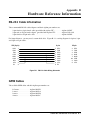
Appendix B Hardware Reference Information
RS-232 Cable Information . . . . . . . . . . . . . . .
GPIB Cables . . . . . . . . . . . . . . . . . . . . . . .
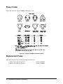
Power Cords . . . . . . . . . . . . . . . . . . . . . . .
Replacement Fuses . . . . . . . . . . . . . . . . . . .
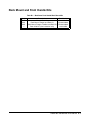
Rack Mount and Front Handle Kits . . . . . . . . . .
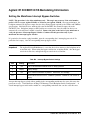
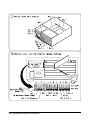
Agilent E1300B/E1301B Backdating Information . .
Setting the Mainframe Interrupt Bypass Switches
.
.
.
.
.
.
.
.
.
.
.
.
.
.
.
.
.
.
.
.
.
.
.
.
.
.
.
.
.
.
.
.
.
.
.
.
.
.
.
.
.
.
.
.
.
.
.
.
.
.
.
.
.
.
.
.
.
.
.
.
.
.
.
.
.
.
.
.
.
.
.
.
.
.
.
.
.
.
.
.
.
.
.
.
.
.
.
.
.
.
.
.
.
.
.
.
.
.
.
.
.
.
.
.
.
.
.
.
.
.
.
.
.
.
.
.
.
.
.
.
.
.
.
.
.
.
B-1
B-1
B-2
B-2
B-3
B-5
B-5
Introduction . . . . . . . . . . . . . . . . . . . . . . . . . . . . . . .
Steps To Debug Programs . . . . . . . . . . . . . . . . . . . . . . .
Step 1: Verify Instrument Communication . . . . . . . . . . . .
Step 2: Reset Each Instrument at the Start of the Program . . .
Step 3: Query the Instruments for Errors . . . . . . . . . . . . .
Step 4: Query All Command Parameter Settings that are Set . .
Step 5: Check the Program is Trying to Enter the Same Amount
Step 6: Check the Instrument’s Arm/Trigger Subsystem . . . .
Step 7: Check that Coupled Commands are Sent as a Group . .
Step 8: Check for Command Synchronization . . . . . . . . . . .
Automating the Debugging Steps . . . . . . . . . . . . . . . . . . .
RN13_RMB Program . . . . . . . . . . . . . . . . . . . . . . . .
Using other Program Languages . . . . . . . . . . . . . . . . . .
Using the Program . . . . . . . . . . . . . . . . . . . . . . . . . .
Program Description . . . . . . . . . . . . . . . . . . . . . . . .
Program Theory . . . . . . . . . . . . . . . . . . . . . . . . . . .
Changing the Program to BASIC . . . . . . . . . . . . . . . . .
.
.
.
.
.
.
.
.
.
.
.
.
.
.
.
.
.
.
.
.
.
.
.
.
.
.
.
.
.
.
.
.
.
.
.
.
.
.
.
.
.
.
.
.
.
.
.
.
.
.
.
.
.
.
.
.
.
.
.
.
.
.
.
.
.
.
.
.
.
.
.
.
.
.
.
.
.
.
.
.
.
.
.
.
.
.
.
.
.
.
.
.
.
.
.
.
.
.
.
.
.
.
.
.
.
.
.
.
.
.
.
.
.
.
.
.
.
.
.
.
.
.
.
.
.
.
.
.
.
.
.
.
.
.
.
.
.
.
.
.
.
.
.
.
.
.
.
.
.
.
.
.
.
.
.
.
.
.
.
.
.
.
.
.
.
.
.
.
.
.
C-1
C-1
C-1
C-3
C-4
C-4
C-5
C-5
C-6
C-6
C-7
C-7
C-7
C-7
C-8
C-9
C-11
Appendix C Debugging VXI SCPI Programs
vi
Warnings and Cautions
WARNING
SHOCK HAZARD. Only service-trained personnel who are aware of the
hazards involved should install, remove, or configure the system. Before
you perform any procedures in this guide, disconnect AC power and field
wiring from the mainframe.
Caution
Do not install modules into the mainframe with power applied. Doing so
may damage the modules and the mainframe.
Caution
STATIC ELECTRICITY. Static electricity is a major cause of component
failure. To prevent damage to the electrical components in the mainframe
and plug-in modules, observe anti-static techniques whenever installing a
module into the mainframe.
vii
Notes
viii
Chapter 1
Installing the System
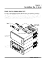
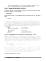
Should I Use this Guide or Agilent VIC?
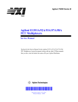
In an effort to make installation of your B-size VME/VXI system as easy as possible, we have included
Agilent VIC (Agilent VME/VXI Installation Consultant). Agilent VIC is a Microsoftâ Windows 3.1ä
compatible program that helps you configure and install your system. If you are using an external Personal
Computer to control the system, we recommend that you configure your system using Agilent VIC instead
of this Configuration Guide. For all other computers, use this Configuration Guide.
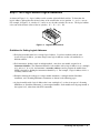
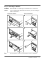
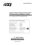
Typical Multimeter
Module
Typical B-Size
Sw itch Module
Typical Terminal Block
Agilent E1300B
Mainframe
Agilent E1301B
Mainframe
Installing t he System 1-1
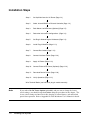
Installation Steps
Step 1:
Set Up Mainframe f or AC Pow er (Page 1-3)
Step 2:
Select Int ernal IBASIC or Ext ernal Controller (Page 1-4)
Step 3:
Rack Mount the Mainframe (Optional) (Page 1-5)
Step 4:
Det ermine Inst rument Configurat ions (Page 1-6)
Step 5:
Set Plug-In Module Logical Addresses (Page 1-9)
Step 6:
Install Plug-In Modules (Page 1-13)
Step 7:
Connect Bus Cables (Page 1-14)
Step 8:
Connect Interface Cables (Page 1-16)
Step 9:
Apply AC Pow er (Page 1-18)
Step 10:
Connect Ext ernal DC Pow er (Optional) (Page 1-19)
Step 11:
Dow nload Device Drivers (Page 1-20)
Step 12:
Verify Operation (Page 1-21)
Wire Terminal Blocks (see individual plug-in module manuals)
Note
1-2
If you ordered the DC Power Option (option 008) and you want to change the factory
switch settings, you should change them before doing the procedures in this chapter. The
factory switch settings are 0mA (no trickle charging of external battery) and non-latched
power-down operation. Refer to Appendix D of the Mainframe User’s Manual for details.
Inst alling the Syst em
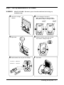
Step 1: Set Up Mainframe for AC Power
WARNING
SHOCK HAZARD. Disconnect power from the mainframe before doing any
installation steps.
A Locate line voltage
select or
B Is the volt age set correct ly?
Yes—go t o Step 2 on the next page
No—perf orm steps C through F below
115 Vac
Setting
230 Vac
Setting
C Open door
D Remove selector drum and re-install
E
F
Install correct fuse for your line voltage
w it h correct voltage f acing out
Close door
115 Vac = 3.0A fuse
230 Vac = 1.5A fuse
Installing t he System 1-3
Step 2: Select Internal IBASIC or External Controller
Set to “ Sys Control” if you are using the internal
IBASIC controller (Option 020, 021, or 022)
*GPIB is the implementation of IEEE Standard 488.1-1978.
1-4
Inst alling the Syst em
Set to “ Talk/Listen” if you are
using an ext ernal GPIB* cont roller
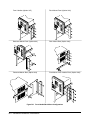
Step 3: Rack Mount the Mainframe (Optional)
Note
Simplified rack mount installation steps are shown here. Refer to the instructions provided
with the rack mount kits for specific details.
A
Install rails and flange nuts
C
Secure mainframe t o rack
B At tach rack mount hardw are
Refer to Appendix B for front handle/rack mount kit part numbers and typical
configurations.
Installing t he System 1-5
Step 4: Determine Instrument Configurations
In this step, you determine the instrument configurations that best suit your application. You will create the
instruments in the next step “ Step 5: Set Plug-In Module Logical Addresses.”
A module can be set up as a single module instrument or as part of a multiple module instrument. For
example, many Agilent plug-in modules can be configured as part of a multiple module Scanning Multimeter
or Switchbox instrument. A single module instrument is programmed and operated independently from the
other modules in the mainframe. Multiple module instruments are programmed and operated together as
one instrument. You designate whether a module is a single module instrument or part of a multiple module
instrument by how you set its logical address switch.
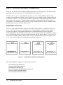
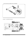
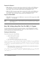
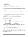
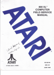
Single Module Instruments
To create a single module instrument, simply set the module’s logical address to a multiple of 8 (such as 8,
16, 24 ...256). In most cases, you can use the factory set logical address—provided no other modules are
set to the same address. Single module instruments are recommended when you want to program the
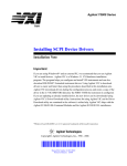
module independently and the module will have little or no interaction with other switching modules. Figure
1-1 is a block diagram showing four single module instruments and their logical addresses. Notice that each
instrument has an GPIB secondary address which is its logical address divided by eight (for example, 72/8
= 09). This secondary address is used when programming the instruments.
HP E1328A
4-Channel D/A Converter
HP E1326B
5 1/2 Digit Multimeter
HP E1332A
4-Channel
Counter/Totalizer
HP E1340A
Arbitrary Function
Generator
Logical Address = 72
(Secondary Address = 09)
Logical Address = 24
(Secondary Address = 03)
Logical Address = 48
(Secondary Address = 06)
Logical Address = 80
(Secondary Address = 10)
Figure 1-1. Single Module Instruments Block Diagram
These modules must be configured as single module instruments:
E1313A Scanning A/D Converter
E1328A 4-Channel D/A Converter
E1330B Quad 8-Bit Digit al I/O
E1331A 32-Channel Isolated Digital Input/Interrupt
E1332A 4-Channel Counter/Tot alizer
E1333A 3-Channel Universal Counter
1-6
Inst alling the Syst em
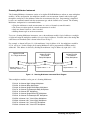
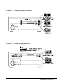
Scanning Multimeter Instrument
The Scanning Multimeter instrument consists of an Agilent E1326B Multimeter and one or more multiplexer
modules. In this configuration, the multiplexer modules scan measurement channels and feed the signal
through the analog bus to the multimeter where the measurements take place. Programming is simplified
because one command controls both the measurement type and the channels to be scanned. The Scanning
Multimeter configuration is recommended when:
•
•
•
•
Using the multimeter to make measurements on a series of channels (scanned channels).
The fastest execution speed for scanned measurements is needed.
Only one channel closure at a time is needed.
Making thermocouple or strain measurements.
To create a Scanning Multimeter instrument, you set the multimeter module’s logical address to a multiple
of eight and assign the multiplexer modules successive logical addresses. You then connect the Analog Bus
cables between all modules (this is shown in detail later in Step 7).
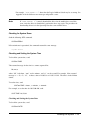
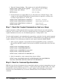
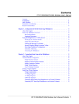
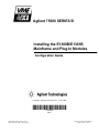
For example, as shown in Figure 1-2, if the multimeter’s logical address is 24, the multiplexers would be
25, 26, and so on. In this example, the Scanning Multimeter will be programmed at GPIB secondary
address 03. This address is derived by dividing the multimeter’s logical address by eight (24/8 = 03).
Agilent E1326B
5 1/2 Digit Mult imeter
Agilent E1345A
16-Channel
Relay Multiplexer
Analog Bus Cable
Logical Address = 24
Secondary Address = 03
Agilent E1345A
16-Channel
Relay Multiplexer
Analog Bus Cable
Logical Address = 25
Logical Address = 26
Figure 1-2. Scanning Multimeter Instrument Block Diagram
These multiplexer modules can be part of a Scanning Multimeter:
E1343A
E1345A
E1346A
E1347A
E1351A
E1352A
E1353A
E1355A
E1356A
E1357A
E1358A
16-Channel High Voltage Multiplexer
16-Channel Relay Multiplexer
48-Channel Single Ended Relay Mult iplexer
16-Channel Thermocouple Relay Multiplexer
16-Channel FET Multiplexer
32-Channel Single-Ended FET Mult iplexer
16-Channel Thermocouple FET Multiplexer
8-Channel 120Ω Strain Relay Multiplexer
8-Channel 350Ω Strain Relay Multiplexer
8-Channel 120Ω Strain FET Multiplexer
8-Channel 350Ω Strain FET Multiplexer
Installing t he System 1-7
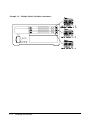
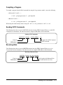
Switchbox Instrument
The Switchbox instrument is composed of one or more switch modules. The single module Switchbox
behaves as an independent instrument as described earlier. When using the multiple module Switchbox, all
switch modules are programmed together and behave as if they are one instrument. The multiple module
Switchbox configuration is recommended when you need to:
• Simplify the programming of multiple switch modules.
• Group multiplexers together to create a larger multiplexer.
• Make scanned measurements but are not using the Agilent E1326B Multimeter (if you are using the
Agilent E1326B, use the Scanning Multimeter configuration).
• Close channels on more than one module simultaneously.
To create a multiple module Switchbox, set one switch module’s logical address to a multiple of eight and
assign the other switch modules successive logical addresses. If applicable, you then connect the Analog Bus
cables between all modules (this is shown in detail later in Step 7).
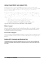
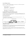
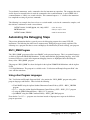
Figure 1-3 is a block diagram example of a Switchbox instrument containing three multiplexers. In this
example, one multiplexer has a logical address of 112, the other multiplexers have successive logical
addresses of 113 and 114. The multiplexers are linked together using the Analog Bus to form a larger
(48-channel) multiplexer. In this example, the Switchbox will be programmed at GPIB secondary address
14. This address is derived by dividing the first multiplexer’s logical address by eight (112/8 = 14).
Agilent E1345A
16-Channel
Relay Multiplexer
Agilent E1345A
16-Channel
Relay Multiplexer
Agilent E1345A
16-Channel
Relay Multiplexer
Analog Bus Cable
Analog Bus Cable
Logical Address = 114
Logical Address = 113
Logical Address = 112
Secondary Address = 14
Figure 1-3. Switchbox Instrument Block Diagram
These modules can be used to form a Switchbox:
E1343A
E1344A
E1345A
E1346A
E1347A
E1351A
E1352A
E1353A
16-Ch.
16-Ch.
16-Ch.
48-Ch.
16-Ch.
16-Ch.
32-Ch.
16-Ch.
High Voltage Multiplexer
Thermocouple High Volt Multiplexer
Relay Multiplexer
Single Ended Relay Mult iplexer
Thermocouple Relay Multiplexer
FET Multiplexer
Single-Ended FET Mult iplexer
Thermocouple FET Multiplexer
E1355A 8-Ch. 120 Ω Strain Relay Multiplexer
E1356A 8-Ch. 350 Ω Strain Relay Multiplexer
1-8
Inst alling the Syst em
E1357A 8-Ch. 120 Ω Strain FET Multiplexer
E1358A 8-Ch. 350 Ω Strain FET Multiplexer
E1361A 4 x 4 Relay Matrix
E1364A 16-Ch. Form C Sw it ch
E1366A 50 Ω RF Multiplexer (2 x 4:1)
E1367A
E1368A
E1369A
E1370A
75 Ω RF Multiplexer (2 x 4:1)
18 GHz Microw ave Sw itch
Microw ave Sw itch Driver
Sw itch Microw ave/At tenuat or Driver
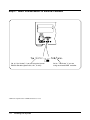
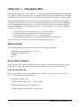
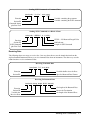
Step 5: Set Plug-In Module Logical Addresses
As shown in Figure 1-4, a logical address switch contains eight individual switches. To determine the
logical address, add together the decimal values of the switches that are set (position 1 = set, 0 = not set).
For example, in Figure 1-4, switches 4, 5, and 6 are set, the other switches are not set. The logical address
is the sum of the decimal values of the set switches: 16 + 32 + 64 = 112.
Figure 1-4. Logical Address Switch
Guidelines for Setting Logical Addresses
• Each plug-in module must have a unique logical address. If you have modules with the same
factory-set logical address, you must change some logical addresses so that each module has a
different address.
• Each instrument, whether single or multiple module, must have one module assigned as an
instrument identifier. The instrument identifier is the module with its logical address set to a multiple
of 8, such as 8, 16, or 24. An instrument’s secondary address (used to program the module from
GPIB) is derived by dividing the instrument identifier by 8. For example, a logical address of 24 is a
secondary address of 03.
• Examples showing the settings for a single module instrument, a multiple module Switchbox
instrument, and a Scanning Multimeter instrument are shown on the following pages.
• A plug-in module with a logical address that is not a multiple of 8, or that is not part of a Scanning
Multimeter or Switchbox instrument, is an unassigned module. Such modules must be programmed at
the register level, rather than with SCPI commands.
Installing t he System 1-9
Locate and Set the Logical Address Switch on all Modules:
Example 1-1. Single Module Instruments:
1-10
Inst alling the Syst em
Example 1-2. Scanning Multimeter Instrument:
Example 1-3. Built-In Scanning Multimeter:
Inst alling the Syst em 1-11
Example 1-4. Multiple Module Switchbox Instrument:
1-12
Inst alling the Syst em
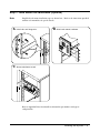
Step 6: Install Plug-In Modules
WARNING
SHOCK HAZARD. Secure modules tightly to the mainframe and cover all unused slots.
Caution
To prevent equipment damage, DISCONNECT the mainframe’s power before installing any
module into the mainframe.
Note
Install B-Size Modules:
Install A-Size Modules:
A
D
B
E
C
F
On older mainframes, you must set the interrupt bypass switches (see Appendix B).
Inst alling the Syst em 1-13
Step 7: Connect Bus Cables (Multiple Module Instruments Only)
The Analog Bus creates an analog signal path between modules. The Analog Bus cables are always used in
the Scanning Multimeter instrument and can also be used to link multiplexers in a Switchbox instrument.
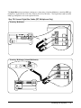
Step 7A: Connect Analog Bus Cables
Scanning Multimeter:
Multimeter Module
Multiplexer Modules
Scanning Multimeter (Internal Multimeter):
Note
1-14
Be sure to properly orient the long analog bus cable--it is not keyed. Make sure that the
connector pin H connects to H, L to L, G to G, ...
Inst alling the Syst em
The Digital Bus ensures maximum scanning rates when using a Scanning Multimeter containing FET type
multiplexers (Agilent E1351A, E1352A, E1353A, E1357A or E1358A). The Digital Bus is not used with
relay type multiplexers such as the Agilent E1345A.
Step 7B: Connect Digital Bus Cables (FET Multiplexers Only)
Scanning Multimeter:
Scanning Multimeter (Internal Multimeter):
Inst alling the Syst em 1-15
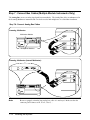
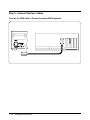
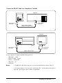
Step 8: Connect Interface Cables
Connect the GPIB Cable to External Controller/GPIB Peripherals:
1-16
Inst alling the Syst em
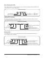
Connect the RS-232 Cable to a Computer or Terminal:
Computer
9-Pin Female
Connector
9-Pin Female
Connector
Agilent 24542U Cable
(shipped w ith Agilent VIC)
Terminal
9-Pin Female
Connector
25-Pin Male
Connector
Agilent 24542G Cable
Set your computer or terminal communications protocol to:
•
•
•
•
•
Baud Rate — 9600
Parity/Data Bit — None/8
Pacing — XON/XOFF
Enq/Ack — Off
1 Stop bit
Notes
1. The RS-232 cable will be necessary if you need to download device drivers (Step 11).
2. For longer distances, you may need a custom built cable. A wiring diagram for 9-pin to
9-pin and 9-pin to 25-pin cables is shown in Appendix B.
Inst alling the Syst em 1-17
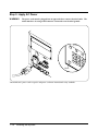
Step 9: Apply AC Power
WARNING
The power cord must be plugged into an approved three-contact electrical outlet. The
outlet must have its own ground connector connected to an electrical ground.
Press
The mainframe’s power cord receptacle and power cord meet international safety standards.
1-18
Inst alling the Syst em
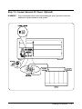
Step 10: Connect External DC Power (Optional)
WARNING
To prevent possible electric shock hazard during DC power operation, connect the
mainframe’s chassis terminal to earth ground.
Inst alling the Syst em 1-19
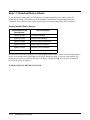
Step 11: Download Device Drivers
If your instrument is not listed in the table below, you must download the device driver so that the
mainframe can interpret the instrument’s SCPI (Standard Commands for Programmable Instruments)
commands. Device drivers enable register-based modules to be programmed using SCPI commands.
Factory Installed Device Drivers:
Register-Based Device
Model Number
Device Description
Agilent E1326B
5 1/2-Digit Multimeter
Agilent E1328A
4-Channel D/A Convert er
Agilent E1330B
Quad 8-Bit Digit al Input/Out put
Agilent E1332A
4-Channel Counter/Totalizer
Agilent E1333A
3-Channel Universal Counter
Most Sw itch Modules
Multiplexers, Matrix, General Purpose
Drivers that are not factory-installed are on a disk shipped with the module. Instructions for downloading the
drivers are included in the Downloading Device Drivers Installation Note. If a driver is not installed, the
mainframe will report the following message to the display (Agilent E1301B) or to an external terminal at
the end of the power-on sequence.
WARNING: DEVICE DRIVER NOT FOUND
1-20
Inst alling the Syst em
Step 12: Verify Operation
This step verifies mainframe operation by:
•
•
•
•
•
Checking for start-up errors
Checking for system errors
Checking/Setting the System Time
Checking/Setting System Date
Determining the Installed Instruments
Use Step 12A to verify using a program supplied on the “Verification and Example Program Disk”, or use
Step 12B to verify using other programs.
Note
If errors are noted or your computer is unable to communicate with the mainframe, go to
Appendix A “ In Case Of Difficulty” for troubleshooting information.
Step 12A: Verify Using The VERF_XXX Program
Use the program called “ VERF_XXX” (the “ XXX” identifies program type) to verify the mainframe
operation. The programs come in three different versions: two for Windows, three for DOS, and one for
computers with BASIC/IBASIC. The programs can be found on the “ Verification and Example Programs”
disks that came with the mainframe. Included on the disks are both the executable files and source codes (to
allow customizing the programs).
Note
To verify mainframe operation using program languages other than those provided, go to
page 1-22.
Programs for DOS
• VERF_CC.EXE - this program requires an Agilent 82335 GPIB Interface Card. The program was
written in the C language using the GPIB Command Library, which comes with the Agilent 82335
GPIB Interface Card.
• VERF_QBC.EXE - this program requires an Agilent 82335 GPIB Interface Card. The program was
written in Microsoft® QuickBASIC using the GPIB Command Library which comes with the Agilent
82335 GPIB Interface Card.
• VERF_QBT.EXE - use this program to verify mainframe operation using the RS-232 port on the PC
computer. The program was written in Microsoft® QuickBASIC.
Inst alling the Syst em 1-21
Programs for Window s
• VERF_VBS.EXE - this program requires either an Agilent 82335, 82540, or 82541 GPIB Interface
Card. The program was written in Visual BASIC using the Agilent Standard Instrument Control
Library (SICL), which comes with the Agilent 82540 or 82541 GPIB Interface Card.
• VERF_VCS.EXE - this program requires either an Agilent 82335, 82540, or 82541 GPIB Interface
Card. The program was written in Visual C/C+ + using the Agilent Standard Instrument Control
Library (SICL), which comes with the Agilent 82540 or 82541 GPIB Interface Card.
Program for BASIC/IBASIC
• VERF_RMB - this program requires the GPIB interface connection of an HP computer that has GPIB
capability (i.e., a series 200/300).
Note
For information on how to control mainframe operation using different program languages,
refer to Chapter 2.
Step 12B: Verifying Using Other Than The VERF_XXX Program
To verify mainframe operation using your own program language, send the following SCPI commands
(Standard Commands for Programmable Instruments). (Refer to the Agilent E1300/E1301 User’s Manual
for more information on the mainframe SCPI commands.)
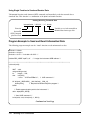
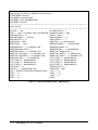
Checking for Start-Up Errors
To check for start-up errors, do the following:
1. Send the following SCPI command:
VXI:CONFigure:DeviceLIST?
2. The returned message should look similar to the one below:
+0,-1,+4095,+1301,-1,+0,HYB,NONE,#H00000000,#H00000000,READY,"","","","SYSTEM IN
STALLED AT SECONDARY ADDR 0";+80,+0,+4095,+65440,-1,+0,REG,A16 ,#H00000000,#H00
000000,READY,"","","","ARB INSTALLED AT SECONDARY ADDR 10";+112,+0,+4095,+65296,
-1,+0,REG,A16 ,#H00000000,#H00000000,READY,"","","","SWITCH INSTALLED AT SECONDA
RY ADDR 14"
3. If the message indicates a start-up error, it may look similar to the one shown below (where the
text in italics shows the actual error message):
+0,-1,+4095,+1301,-1,+0,HYB,NONE,#H00000000,#H00000000,READY,"","","","CNFG ERRO
R: 13“;+112,+0,+4095,+65280,-1,+0,REG,A16 ,#H00000000,#H00000000,READY,”","","",
“CNFG ERROR: 13”
1-22
Inst alling the Syst em
For example, “ CNFG ERROR: 13” shows that the Logical Address Switch may be set wrong. See
Appendix A for the different error messages and possible causes.
If “ CNFG ERROR: 3” is noted, download the driver for the module that caused this
error. After the driver is downloaded, perform the above step again. The procedure for
downloading drivers is in the Operating Note that came with the driver.
Note
Checking for System Errors
Send the following SCPI command:
SYSTem:ERRor?
If the mainframe is operational, the command returns this error message:
+0,"No error"
Checking and Setting the System Time
To check the system time, send:
SYSTem:TIME?
The returned message for the time is a comma separated list:
hh,mm,ss
where “ hh” is the hour, “ mm” are the minutes, and “ss” are the second. For example, if the returned
message is “ + 23,+ 5,+ 38” , it shows a time of 23:05:38 or 11:05:39 P.M.. The time is in the 24 hour
format.
To set the time, send:
SYSTem:TIME < hour> ,< minute> ,< second>
For example, to set the time for 10:15:00 AM, send:
SYST:TIME 10,15,00
Checking and Setting the System Date
To check the system date, send:
SYSTem:DATE?
Inst alling the Syst em 1-23
The returned message for the date is a comma separated list:
yyyy,mm,dd
where “ yyyy” is the year, “mm” is the month, and “ dd” is the day. For example, if the returned message is
“ + 1994,+ 7,+ 24” , it shows a date of 7/24/1994 or July 24,1994.
To set the system date, send:
SYSTem:DATE < year> ,< month> ,< day>
For example, to set the date for May 31, 1994, send:
SYST:DATE 1994,5,31
Where to go Next
Your B-Size system should now be installed and operational. Next, you should wire the terminal blocks and
begin programming. Refer to the individual module manuals for wiring schematics and specific terminal
block wiring information.
The next chapter (Chapter 2) shows how to program instruments using a variety of languages. Shipped with
the command module are two “ Verification and Example Programs” disks. These disks (one DOS and one
LIF disk) contain example programs in various languages. Refer to the “ README” files on the disks for
information on the various programs on the disks.
1-24
Inst alling the Syst em
Chapter 2
Sending SCPI Commands
This chapter shows how to send Standard Commands for Programmable Instruments (SCPI) and IEEE 488.2
Common Commands to the Agilent E1300/E1301 Mainframe from a computer over the General Purpose
Interface Bus (GPIB)*, or from a Terminal. Chapter contents are:
•
•
•
•
•
Using Visual BASIC and Agilent SICL (Agilent Standard Instrument Control Library)
Using C/C+ + and Agilent SICL (Agilent Standard Instrument Control Library) . . . .
Using C and the GPIB Command Library . . . . . . . . . . . . . . . . . . . . . . . . . . . . .
Using BASIC/IBASIC . . . . . . . . . . . . . . . . . . . . . . . . . . . . . . . . . . . . . . . . . .
Using a Terminal . . . . . . . . . . . . . . . . . . . . . . . . . . . . . . . . . . . . . . . . . . . . .
.
.
.
.
.
.
.
.
.
.
.
.
.
.
.
.
.
.
.
.
.
.
.
.
.
.
.
.
.
.
2-2
2-5
2-10
2-13
2-15
Verification and Example Programs
Shipped with the Agilent E1300/E1301 Mainframe are two disks that contain verification and example
programs for the mainframe. One disk (Agilent Part Number: E1300-10307) is in the LIF format and
contains programs written for BASIC/IBASIC. The other disk (Agilent Part Number: E1300-10308) is in the
DOS format and contains programs written in C/C+ + , Visual BASIC, QuickBASIC, and BASIC/IBASIC.
Refer to the “ README” files on the disks for information on the various programs on the disks.
Primary and Secondary GPIB Addressing
The plug-in modules in the mainframe are considered individual instruments. This requires them to have a
unique GPIB Secondary address. This is because the Primary GPIB address of each instrument is the same,
which is the primary address of the mainframe itself. To determine the Secondary GPIB address, divide the
Logical Address of an instrument by 8.
For example, a typical GPIB address is:
70903
where:
• “ 7” is the Select Code
• “ 09” is the Primary GPIB address of the Agilent E1300/E1301 (default value)
• “ 03” is the Secondary GPIB address (default value of the Agilent E1326 Multimeter); the “ 03”
Secondary GPIB address is derived from a Logical Address of 24 (i.e., 24 / 8 = 3)
* GPIB is the implementation of the IEEE Standard 488.1-1978
Sending SCPI Commands 2-1
Using Visual BASIC and Agilent SICL
The following shows how to use the Visual BASIC program language (version 3.0) with the Agilent
Standard Instrument Control Library (SICL) and the Agilent 82335, Agilent 82340, or Agilent 82341 GPIB
Interface Card. Both the GPIB Card and SICL are used in a PC type computer under Microsoft®
Windows or Windows NT.
The Agilent Standard Instrument Control Library provides the sub calls to send the SCPI commands that
control instrument operation. To send a SCPI command, the appropriate sub call requires the GPIB address
of the instrument and the SCPI command. To receive data from the instrument, the appropriate sub call
requires the GPIB address and the returned data format. To send commands and to receive data is a multiple
step process, as follows:
1.
2.
3.
4.
SICL first opens an I/O session between Visual BASIC and the instrument.
Send the commands and return the data to and from the instrument.
Close the the I/O session between Visual BASIC and the mainframe.
If using Microsoft® Windows, cleanup SICL (not needed for Windows NT).
Typical sub calls are as follows (refer to the “ SICL Manual” for other commands):
What’s Needed
Include the “SICL.BAS” program file to the Visual BASIC project. This file came with SICL. To add the
file, press Ctrl-D and enter the path and file name, or select the Add File menu under the File menu (see
Visual BASIC documentation for more information).
How to Run a Program
You can run the program in the Visual BASIC environment or compile it to make an executable file. Use the
appropriate menu in the environment to make the executable file. Note that the file can only operate under
Windows.
Sending SCPI Commands and Receiving Data
The following shows how to send SCPI commands and receive data. To do this, open the communication
path between Visual BASIC and the instrument. The following shows how to open the path, and send and
receive data.
2-2
Sending SCPI Commands
Open Communication Path
Use the iopen subproutine to open the communication path between the instrument and Visual BASIC. The
command requires the complete GPIB address.
Open the I/O Session
Addr = iopen(" hpib7,9,0" )
I/O Address (e.g., GPIB Address)
I/O Interface (i.e., GPIB Card)
Session Identifier
Opens I/O Session
Sending SCPI Commands
The following shows how to send SCPI commands to an instrument using the iw rite subroutine from the
Agilent Standard Instrument Control Library (SICL).
Sending SCPI Commands
Call iw rite(Addr, ByVal “ ABORt” + Chr$(10), 6, 1, Actual)
Returned Length of the Command
End Indicator
Length of SCPI Command
SCPI Command plus Line Feed
Sub Call
Session ID
Program Control
Receiving Data
The following shows how to use the iread subroutine from the Agilent Standard Instrument Library to
receive string data from an instrument.
Receiving String Data
Call iread(Addr, ByVal RdMsg, Lengt h, 0, Actual)
Sub Call
Session ID
Program Control
Get length of the Returned Data
Reason for Termination
Set length of the Returned Data
String Variable that Receives Data
Sending SCPI Commands 2-3
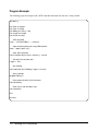
Program Example
The following program example sends a SCPI command and returns the data into a string variable.
Sub Main ()
Dim
Dim
Dim
Dim
Dim
Addr As Integer
Cmd As String
RdMsg As St ring * 256
Lengt h As Integer
Act ual As Long
’ SCPI command
Cmd = “ SYSTem:ERRor?” + Chr$(10)
’ Open communication path using GPIB address
Addr = iopen(" hpib7,9,0" )
’ Send SCPI command
Call iw rit e(Addr, ByVal Cmd, Len(Cmd), 1, Actual)
’ Set space f or returned data
Length = 256
’ Get readings
Call iread(Addr, ByVal RdMsg, Length, 0, Act ual)
’ Show readings
MsgBox RdMsg, 0
’ Close communication w it h inst rument
Call iclose(Addr)
’ Clean up sicl (f or Window s only)
Call siclcleanup
End
End Sub
2-4
Sending SCPI Commands
Using C/C+ + and Agilent SICL
The following shows how to use the Visual C/C+ + program language with the Agilent Standard Instrument
Control Library (SICL) and the Agilent 82335, Agilent 82340, or Agilent 82341 GPIB Interface Card. Both
the GPIB Card and SICL are used in a PC type computer under Microsoft® Windows or Windows NT.
The Agilent Standard Instrument Control Library provides the functions to send the SCPI commands that
control instrument operation. To send a SCPI command, the appropriate function requires the GPIB address
of the instrument and the SCPI command. To receive data from the mainframe, the appropriate function
requires the GPIB address and the returned data format. To send commands and receive data is a multiple
step process, as follows:
1.
2.
3.
4.
SICL first opens an I/O session between C/C+ + and the mainframe.
Send the commands and return the data to and from the mainframe.
Close the the I/O session between C/C+ + and the mainframe.
If using Microsoft® Windows, cleanup SICL (not needed for Windows NT).
Typical functions are as follows (refer to the SICL Manual for other commands):
What’s Needed
You need the the following libraries and header files. These are supplied with SICL.
•
•
•
•
msapp16.lib - for Microsoft® Visual C and C+ +
bcapp16.lib - Borland C and C+ +
sicl16.lib
sicl.h
How to Run a Program
To run a program, first compile and link the program to make an executable file using the Large memory
model. You can compile from the command line or the Windows interface. The two methods are:
From the Command Line
Make sure the program to be compiled and the appropriate libraries are in a project file. Do this in the
C/C+ + environment. Then do the following:
• For Borland compilers, type:
MAKE < project_name> .MAK
and press Enter
• For Microsoft compilers used in Windows, type:
NMAKE < project_name> .MAK
and press Enter
Sending SCPI Commands 2-5
From the Window s Interface
Select the C/C+ + Windows environment and make sure the program to be compiled and the appropriate
libraries are in a project file. Then do the following:
• For Borland compilers, select:
Project | Open Project
to open the project, then
Compile | Build All
to compile the program
• For Microsoft compilers used in Windows, type:
Project | Open
to open the project, then
Project | Re-build All to compile the program
Sending SCPI Commands and Receiving Data
The following shows how to send SCPI commands and receive data using several different functions. To do
this, open the communication path between Visual C/C+ + and the instrument. The following shows how to
open the path, and send and receive data.
Open Communication Path
Use the iopen function to open the communication path between the instrument and Visual C/C+ + . The
command requires the complete GPIB address.
Open the I/O Session
addr = iopen(" hpib7,9,0" );
Session Identifier variable
Opens I/O Session
I/O Address (i.e., GPIB Address)
I/O Interface (e.g., GPIB Card)
Sending SCPI Commands
The following shows two ways to send SCPI commands. One way uses the iprintf function from the Agilent
Standard Instrument Library to send the commands as formatted data to the instrument. The other way uses
the iw rit e function to send the commands in a block of data.
Use the iw rite function to send SCPI commands that will not change and use the iprintf function to send
SCPI commands where the parameters may change. The format for the iprint f command are the same format
used by C/C+ + (e.g., %s, %i, %f, etc.).
2-6
Sending SCPI Commands
Sending SCPI Commands as Formatted Data
iprintf(addr, “ % s %i\n” , cmd, parm);
Variable containing the parameter
Variable containing the SCPI command
Function
Session ID
Command format
plus Line Feed
Sending SCPI Commands as a Block of Data
iw rite(addr, “ ABORt \n” , 6, 1, NULL);
NULL = No Returned Length Value
End Indicator
Length of SCPI Command
Function
Session ID
SCPI Command
plus Line Feed
Receiving Data
The following shows two ways to receive data. One way shows how to use the iscanf function from the
Agilent Standard Instrument Library to receive formatted data from an instrument. The other way uses the
iread function to receive unformatted data.
Receiving Formatted Data
iscanf(addr, " %f " , &rd_data);
Variable that Receives the Data
Specifies Returned Data Format
Function
Session ID
Receiving Unformatted Data
iread(addr, rdmsg, length, NULL, &actual);
Function
Session ID
Variable that
Receives Data
Get length of the Returned Data
Reason for Termination
Set length of the Returned Data
Sending SCPI Commands 2-7
Using Single Function to Send and Receive Data
The ipromptf function sends formatted SCPI commands and immediately reads the returned data as
formatted data. This function is a combination of the iprintf and iscanf functions.
Sending/Receiving Formatted Data
ipromptf (addr, “ * OPC?\n” , “ %i” , &into);
Variable to received returned data
Returned data format specifier
Function
Session ID
SCPI Command
plus Line Feed
Program Example to Send and Read Unformatted Data
The following program example uses the “ iread” function to read unformatted raw data.
#include < stdio.h>
#include < string.h>
#include < sicl.h> /* Included w ith SICL * /
#define DEV_ADDR " hpib7,9,0"
/* Assign the instrument GPIB address * /
/* * * * * * * * * * * * * * * * * * * * * * * * * * * * * * * * * * * * * * * * * * * * * * * * * * * * * * * * * * * * * * * * * /
void main(void)
{
INST addr;
unsigned long act ual;
int
length = 256;
char
into[256],
* cmd = “ SYSTem:ERRor?\n” ; /* SCPI command * /
#if defined(__BORLANDC__) && !defined(__WIN_32)
_InitEasyWin();
/* Required for Borland EasyWin program * /
#endif
/* Enable communication pat h to the instrument * /
addr= iopen(DEV_ADDR);
/* Send SCPI command * /
iw rite(addr, cmd, strlen(cmd), 1, NULL);
Continued on Next Page
2-8
Sending SCPI Commands
/* Read returned data * /
iread(addr, into, length, NULL, &actual);
/* NULL terminates result string and print the results * /
if (actual)
{
into[actual - 1] = (char) 0;
print f(“ \n%s” , int o);
}
/* Close communication * /
iclose(addr);
/* Release SICL resource allocat ion; not needed for Window s NT * /
_siclcleanup();
}
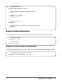
Example to Read Formatted Data
To read formatted data, replace the “ iread” function in the above program with the “ iscanf ” function.
/* Read returned data * /
iscanf(addr, “ %t” , into);
/* Print the result s * /
print f(“ \n%s” , int o);
Example to Send and Read Formatted Data
To send and read formatted data, replace the “ iscanf ” and “ iprintf ” functions with the “ ipromptf ” function.
/* Send SCPI command and read returned data * /
ipromptf (addr, “ SYSTem:ERRor?\n” , “ %t ” , int o);
Sending SCPI Commands 2-9
Using C and the GPIB Command Library
The following shows how to use the C program language with the GPIB Command Library and the Agilent
82335 GPIB Interface Card (the command library is supplied with the GPIB Card). Both the GPIB Card and
Command Library are used in a PC type computer.
The GPIB Command Library provides the functions to send the SCPI commands that control instrument
operation. To send a SCPI command, the C function requires the GPIB address of the instrument (e.g.,
70900) and the SCPI command. To receive data from the instrument, the C function requires the GPIB
address and the returned data format. Typical functions to send commands and to receive data are as follows
(refer to the GPIB Command Library Manual for other commands).
Supported C Programs
The supported C programs are:
• Microsoft® C and C+ +
• Borland C and C+ +
What’s Needed
You need the following libraries and header files. These are supplied with the command library.
• clhpib.lib - for Microsoft® C and C+
• tchhpib.lib - for Borland C and C+ +
• cfunc.h - for the Small memory model only
Executing a Program
To execute a program, first compile and link the program to make an executable file. To compile the
program from the command line:
• Link the appropriate GPIB C library (from the GPIB Command Library files). Use one of the
following libraries:
– Microsoft® C + and C+ + , and QuickC©: clhpib.lib
– Borland C and C+ + : tchhpib.lib
• If using the Small memory model, include “cfunc.h” header file (from the GPIB Command Library
files). This file is not needed when using the Large/Huge memory models.
• Be sure the necessary paths have been added to the AUTOEXEC.BAT file for the compilers to find
the correct library and header file (see your C Language documentation to set the proper paths).
2-10
Sending SCPI Commands
Compiling a Program
To compile a program from the DOS command line using the Large memory model, execute the following:
• Microsoft® C/ and C+ + :
cl /AL < path\program name.C> path\clhpib.lib
• Borland C and C+ + :
tcc -ml < path\program name.C> path\tchhpib.lib
When using the Small memory model, change the “AL” or “-ml” parameters to “AS” or “ -ms” .
Sending SCPI Commands
The following shows how to use the IOUTPUTS function from the GPIB Command Library to send SCPI
commands to an instrument. The function needs the complete GPIB address of the instrument.
Sending SCPI Commands
IOOUTPUTS (70900L, “ SYSTem:ERRor?” , 13);
Length of the SCPI Command
SCPI Command
Function
GPIB Address
Receiving Data
The following shows how to use the IOENTERS function from the GPIB Command Library to receive
character data from an instrument. The function needs the complete GPIB address of the instrument.
Receiving Character Data
IOENTERS (70900L, get_data, &length);
Function
GPIB Address
Get length of the Returned Data
Variable that Receives Data
Sending SCPI Commands 2-11
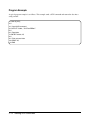
Program Example
The following program example sends a SCPI command and returns the data into a character string.
#include < stdio.h>
#include < string.h>
#include < cfunc.h>
/* This file is from t he GPIB Command Library Disk * /
#define ADDR 70900L /* Defines the GPIB address * /
/* * * * * * * * * * * * * * * * * * * * * * * * * * * * * * * * * * * * * * * * * * * * * * * * * * * * * * * * * * * * * * * * /
void main(void)
{
char
* cmd = “ SYSTem:ERRor?” ,
/* SCPI command * /
rd_msg[257];
int
length = 256;
/* Send SCPI command * /
IOOUTPUTS(ADDR, cmd, st rlen(cmd));
/* Read returned data * /
IOENTERS(ADDR, rd_msg, &lengt h);
/* Print returned data * /
print f(“ \n%s” ,rd_msg);
}
2-12
Sending SCPI Commands
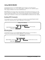
Using BASIC/IBASIC
The following shows how to use the BASIC/IBASIC program language (version 5.0 and above).
BASIC/IBASIC languages are in a variety of HP computers, including many Series 200/300 computers.
These computers normally have the means for GPIB connections.
BASIC/IBASIC have the means to directly send commands to the instruments and to directly receive data
from the instruments over GPIB. To send a SCPI command, the program requires the GPIB address of the
instrument and the SCPI command. To receive data from the instrument, the program requires the GPIB
address. Typical commands are as follows (refer to the BASIC/IBASIC documentation for other commands).
Sending SCPI Commands
The following shows how to send SCPI commands to an instrument using the BASIC/IBASIC OUTPUT
command. The command needs the complete GPIB address of the instrument.
Sending SCPI Commands
OUTPUT 70900;" SYSTem:ERRor?"
SCPI Command
BASIC/IBASIC Command
GPIB Address
Receiving Data
The following shows how to use the hp BASIC/IBASIC ENTER command to receive data from an
instrument. The command needs the complete GPIB address of the instrument.
Receiving Data
ENTER 70900;Get_data$
BASIC/IBASIC Command
GPIB Address
Variable that Receives Data
Sending SCPI Commands 2-13
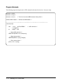
Program Example
A typical program example is as follows. This example sends a SCPI command and returns the data into a
string variable.
10 DIM A$[256]
20 !
30 ! Send SCPI command
40 OUTPUT 70900.;" SYSTem:ERRor?"
50 !
60 ! Read dat a
70 ENTER 70900.;A$
80 !
90 ! Print returned data
100 PRINT A$
110 END
2-14
Sending SCPI Commands
Using a Terminal
The following shows how to use a supported terminal to send SCPI commands to an instrument and display
returned data. The supported terminals are:
•
•
•
•
•
•
•
•
HP 700/92
HP 700/94
HP 700/22
HP 700/43
DEC®VT100®
DEC®VT220®
WYSE®WY-30
Agilent AdvanceLink terminal emulation software (configured as an HP 2392A Terminal)
Connecting the Terminal
The terminal must be connected to the RS-232 connector on the computer. The Baud Rate must be 9600.
Sending SCPI Commands
To send SCPI commands to an instrument, make sure the instrument is selected. You can select the
instrument either in the main menu or in an instrument menu, as follows:
Select Instrument from Main Menu
The Main Menu is the one that is shown after the mainframe is turned on and it has gone through its turn-on
cycle. The prompt “ Select an instrument ” is displayed when the mainframe is ready to select an
instrument. Do the following:
1. Supported Terminal: The installed instruments are shown on the terminal’s functions keys. To
select an instrument, press the appropriate function key. For example, if you wish to select the
system (i.e., mainframe), press the function key labeled “ SYSTEM ” .
2. Non-Supported Terminal: Do one of the following:
a. Type:
SI < instrument name>
press Return
where < instrument name> is the name of the instrument to be selected. For example, the
function key labeled “ VOLTMTR” for the Agilent E1326 Multimeter.
or type:
SA < logical address>
Sending SCPI Commands 2-15
where < logical address> is the Logical Address of the instrument to be selected. For
example, “ SA 24 ” selects the Agilent E1326 Multimeter.
Select Instrument from an Instrument Menu
An Instrument Menu is normally indicated by the instrument title shown on the display. For example, if the
system is selected, the title is typically displayed as “ SYSTEM_0: ” . Do the following:
1. Supported Terminal: Do the following:
a. Press the function key labeled “ UTILS” , if displayed. Continue with the next step if the label
is displayed or not.
b. Press the function key labeled “ SEL_INST” . This should bring you to the Main Menu (i.e., the
“ Select an inst rument. ” prompt shown). Use the procedure under the “ Select Instrument
from Main Menu” heading to select the instrument.
2. Non-Supported Terminal: Press Ctrl-D to select the Main Menu (i.e., the “ Select an
inst rument. ” prompt shown). Use the procedure under the “ Select Instrument from Main Menu”
heading to select the instrument.
Sending the Commands
Once the instrument menu is shown, type in the SCPI command and press ’Return’. For example, to display
an error message, type:
SYST:ERR?
and the returned error message from the selected instrument will be displayed.
2-16
Sending SCPI Commands
Appendix A
In Case Of Difficulty
This appendix gives possible failures and troubleshooting information for the mainframe. Included are
start-up and system errors, and their descriptions.
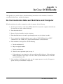
No Communication Between Mainframe and Computer
When the mainframe is unable to communicate with the computer, do the following:
1. Check for poor interface connections (GPIB or Serial I/O) between the computer and mainframe.
If connections are good, continue with step 2.
2. Turn the mainframe off.
3. Remove all plug-in modules from the mainframe.
4. Turn the mainframe on; wait until it goes through its turn on cycle (about 8 seconds).
5. Try to communicate with the mainframe again (send the “VXI:CONFigure:DeviceLIST?”
command or use the “ VERF_XXX” program from the B-Size Verification Disk).
6. If the mainframe is now operative, do the following:
a. Turn the mainframe off.
b. Plug in one plug-in module.
c. Turn the mainframe on.
d. Check for correct operation again (see step 4).
e. If the mainframe is now inoperative, the last module installed is defective. If the mainframe
module still operates, repeat steps 6-a to 6-d to check any other modules one at a time until
you find the defective one.
7. If the mainframe is still inoperative, make sure the computer operates correctly. If it appear to
operate correctly, the mainframe is inoperative.
In Case Of Dif ficult y
A-1
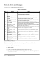
Start-Up Errors and Messages
The Start-up errors and descriptions are listed in Table A-1.
Table A-1. Start-Up Errors
Code
Message
Cause
1
Failed Device
VXI device f ailed its self test.
2
Unable to combine device
Device t ype cannot combine into an instrument such as a
scanning voltmeter or a sw itchbox.
3
Config w arning. Device driver
not found
Identification of device does not match list of drivers available.
5
Config error 5. A24 memory
overflow
More A24 memory installed in the mainf rame that can be
configured into available A24 memory space.
8
Config error 8. Inaccessible
A24 memory
An A24 memory device overlaps a memory space reserved in
the mainframe’ s operating syst em.
10
Config error 10. Insufficient
syst em memory
Too many instruments installed f or the amount of RAM
available in the mainframe/command module. Cannot configure
the instruments. Only the mainframe is started.
11
Config error 11. Invalid
instrument address
A device t hat is not part of a combined instrument has a logical
address t hat is not a multiple of 8.
13
Config error 13. Logical
address or or IACK sw itch set
w rong
Duplicate logical addresses set or interrupt bypass sw it ches set
improperly. Only t he mainframe is started.
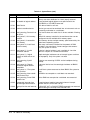
29
Config w arning. Sysfail
detect ed
A device asserted SYSFAIL on t he backplane during startup.
30
Config error 30. Pseudo
instrument logical address
unavailable
A physical device has the same logical address as IBASIC (i.e.,
30).
31
Config error 31. File system
start up failed
Insuff icient syst em resources to allow the IBASIC file system
to start.
45
Config w arning. Non-volatile
RAM cont ent s lost
NVRAM w as corrupted or a cold boot w as executed.
48
Config w arning. Driver RAM
contents lost.
Driver RAM w as corrupt ed or a cold boot w as execut ed.
Error 1: Failed Device
This indicates that a plug-in module in the mainframe is inoperative. To determine which module is
defective, do the following:
1. Remove AC power from the mainframe.
2. Unplug a module.
3. Re-apply AC power to the mainframe and check for Start-Up errors again.
4. If the error has not returned, the last module unplugged is the cause. Otherwise, repeat steps 1 to
3 to check the other modules.
A-2
In Case Of Dif ficult y
Error 3: Config warning. Device driver not found
The mainframe generates this error when it detects a module that has no driver present. Many instruments,
like the Agilent E1326 Multimeter and Agilent E1345/E1346/E1347, etc. switches, have the built-in drivers
in ROM. For other modules, like the Agilent E1340 Arbitrary Function Generator, its driver must be
downloaded.
When Error: 3 is generated, check and be sure all drivers are installed. Refer to the Downloadable Driver
Operating Note that came with module to download the drivers.
Error 10: Config error 10. Insufficient system memory
The system has a set amount of RAM memory available for use. If attempting to download instrument
drivers that require more RAM memory than available, the system generates this error message. Either
install more RAM or remove a downloadable driver to get more memory.
Error 11: Config error 11. Invalid instrument address
The mainframe generates this error if a Logical Address of a module is other than a multiple of 8. The only
exception is the Scanning Voltmeter or Switchbox configuration. However, the first module in these
configurations must be set at a multiple of 8.
Error 13: Config error 13. Logical address or IACK switch set wrong
Multiple modules with the same Logical Address causes this error. Be sure each module has its own unique
Logical Address.
System Errors and Messages
All system errors generated by the mainframe are stored into an error queue until full. When full, all
subsequent errors are not stored. Before the error queue is full, the last error message stored is called:
-350,“ Too many errors”
Reading the Error Queue
The SCPI command “ SYSTem:ERRor?” reads the error queue and returns the error message. The command
reads the oldest message to the newest. Whenever a message is read, it is removed from the queue. When all
messages are removed, the command returns:
+ 0,“ No error”
In Case Of Dif ficult y
A-3
Error Types
The returned error message consists of a number and a message. A positive number shows instrument
specific errors. Negative numbers determined different types of errors as summarized in Table A-2. The
different negative numbered types are explained following the table.
Table A-2. Negative Error Numbers
Error Number
Error Type
-199 to -100
Command Errors
-299 to -200
Execution Errors
-399 to -300
Device-Specific Errors
-499 to -400
Query Errors
Command Errors
The mainframe cannot execute or understand a command. Possible causes are:
• A syntax error. For example, wrong data type for a particular command was received.
• A command was not recognized. For example, the SCPI or Common Command is incorrect.
Execution Errors
The mainframe is unable to perform the action or operation requested by the command. Possible causes are:
• A parameter within the command is outside the limits or inconsistent with the capabilities of the
mainframe.
• A valid command cannot be executed due to a failure in the mainframe.
Device-Specific Errors
This shows that an operation cannot complete due to an abnormal hardware or firmware condition, like a
self-test failure.
Query Errors
This shows that a problem has occurred in the output queue. Possible causes are:
• An attempt was made to read an empty output queue (i.e., no data present in the queue).
• Data in the output queue has been lost for some unknown reason.
System Error Message Listing
For a listing of all system errors, refer to Tables A-3 and A-4.
A-4
In Case Of Dif ficult y
Table A-3. System Errors
Code
Message
Cause
-101
Invalid character
Unrecognized character in specified parameter.
-102
Syntax error
Command is missing a space or comma betw een parameters.
-103
Invalid separator
Command parameter is separated by some character other
t han a comma.
-104
Data type error
The w rong data type (i.e. number, charact er, string
expression) w as used w hen specifying a parameter.
-108
Parameter not allow ed
Paramet er specified in a command w hich does not require
one (e.g., SYSTem:ERRor? 10).
-109
Missing parameter
No parameter specified in the command in w hich a
parameter is required.
-113
Undefined header
Command header w as incorrectly specified (e.g., * IDN1?).
-123
Numeric overf low
A parameter specifies a value greater than the command
allow s.
-128
Numeric data not allow ed
A number w as specified f or a parameter w hen a lett er is
required.
-131
Invalid suff ix
Paramet er suff ix incorrectly specified (e.g. .SSECOND rat her
t han .SS or .SSEC).
-138
Suffix not allow ed
Paramet er suff ix is specified w hen one is not allow ed.
-141
Invalid character dat a
The discrete parameter specified is not allow ed (e.g.
TRIG:SOUR INT - INT is not a choice.).
-178
Expression data not allow ed
A parameter is enclosed in parentheses t hat should not be.
-211
Trigger Ignored
Trigger occurred w hile the Pacer is in t he idle stat e, or a
t rigger occurred from a source other than the specified
source.
-222
Data out of range
The parameter value specif ied is t oo large or too small.
-224
Illegal paramet er value
The numeric value specif ied is not allow ed.
-240
Hardw are error
Hardw are error detected during pow er-on cycle. Return
mainframe to Agilent Technologies f or repair.
-310
Syst em error
If caused by * DMC, then macro memory is full.
-350
Too many errors
The error queue is full as more than 30 errors have occurred.
-410
Query interrupted
Dat a is not read from t he output buffer bef ore another
command is execut ed.
-420
Query unterminated
Controller tried to read dat a w it hout first sending a complete
query message.
-430
Query deadlocked
Command execution cannot cont inue since the mainf rame’ s
command input, and dat a output buff ers are full. Clearing the
instrument restores control.
+ 1500 External trigger source
“ Event In” signal already allocat ed to anot her already
allocated instrument such as a Sw itchbox.
+ 2002 Invalid logical address
A value less than 0 or great er than 255 w as specified f or a
logical address.
In Case Of Dif ficult y
A-5
Table A-4. System Errors (cont.)
Code
Message
Cause
+ 2003 Invalid w ord address
An odd address w as specif ied for a 16 bit read or w rite.
Alw ays use even addresses for 16 bit (w ord) accesses.
+ 2005 No module at logical address
A non-existent logical address w as specif ied w ith the
VXI:READ? or VXI:WRITE command.
+ 2101 Failed Device
VXI device failed its self test .
+ 2102 Unable to combine device
Device type can not be combined into an instrument such as
a scanning multimeter or a sw itchbox.
+ 2103 Conf ig w arning, Device driver
not f ound
ID of device does not match list of drivers available. Warning
only.
+ 2105 Conf ig error 5, A24 memory
overflow
More A24 memory installed in t he mainframe t han can be
configured into the available A24 memory space.
+ 2108 Conf ig error 8, Inaccessible
A24 memory
A24 memory device overlaps memory space reserved by the
mainframe’s operating system.
+ 2110 Conf ig error 10, Insuff icient
system memory
Too many instrument s installed for the amount of RAM
inst alled in the mainframe. Cannot configure inst ruments.
Only the system is start ed.
+ 2111 Conf ig error 11, Invalid
instrument address
A device’ s logical address is not a mult iple of 8 and the
device is not part of a combined instrument .
+ 2113 Conf ig error 13, Logical
address or IACK sw it ch set
w rong
Duplicate logical addresses set or int errupt bypass sw itches
set improperly. Only t he system is started.
+ 2129 Conf ig w arning, Sysfail
detected
A device w as asserting SYSFAIL on the backplane during
start up.
+ 2130 Conf ig error 30, Pseudo
instrument logical address
unavailable
A physical device has the same logical address as IBASIC
(240).
+ 2131 Conf ig error 31, File syst em
st art up f ailed
Insufficient system resources to allow IBASIC f ile syst em t o
start .
+ 2145 Conf ig w arning, Non-volat ile
RAM contents lost
NVRAM w as corrupted or a cold boot w as executed.
+ 2148 Conf ig w arning, Driver RAM
cont ent s lost
Driver RAM w as corrupted or a cold boot w as executed.
+ 2202 Unexpect ed interrupt from
non-message based module
A register-based module interrupted w hen an interrupt
service routine had not been set up.
+ 2809 Interrupt line has not been set
up
A DIAG:INT:ACT or DIAG:INT:RESP command w as executed
before setting t he interrupt w ith DIAG:INT:SET.
A-6
In Case Of Dif ficult y
Appendix B
Hardware Reference Information
RS-232 Cable Information
The recommended RS-232 cables/adapters and their Agilent part numbers are:
9-pin female to 9-pin female cable (provided with Agilent VIC) . . . . . . Agilent 24542U
9-pin male to 25-pin female adapter (provided with Agilent VIC) . . . . Agilent 5181-6641
9-pin female to 25-pin male cable . . . . . . . . . . . . . . . . . . . . . . . . . Agilent 24542G
For longer distances, you may need a custom built cable. Figure B-1 is a wiring diagram for 9-pin to 9-pin
and 9-pin to 25-pin cables.
VXI (9 pin)
DCD
RXD
TXD
DTR
GND
DSR
RTS
CTS
RI
9 pin
7
3
2
6
5
4
1
8
9
1
2
3
4
5
6
7
8
9
RTS
TXD
RTD
DSR
GND
DTR
DCD
CTS
RI
25 pin
4
2
3
6
7
20
8
5
RTS
TXD
RTD
DSR
GND
DTR
DCD
CTS
Figure B-1. RS-232 Cable Wiring Schematic
GPIB Cables
The available GPIB cables and their Agilent part numbers are:
0.5 meter .
1 meter . .
2 meter . .
4 meter . .
.
.
.
.
.
.
.
.
.
.
.
.
.
.
.
.
.
.
.
.
.
.
.
.
.
.
.
.
.
.
.
.
.
.
.
.
.
.
.
.
Agilent 10833D
Agilent 10833A
Agilent 10833B
Agilent 10833C
Hardw are Ref erence Information B-1
Power Cords
Figure B-2 shows the Agilent E1300B/E1301B power cords..
Aust ralia
Figure B-2. Agilent E1300B/E1301B Power Cords
Replacement Fuses
The replacement line fuses and their Agilent part numbers are:
1.5A Fuse (for 115VAC operation) . . . . . . . . . . . . . . . Agilent 2110-0304
3.0A Fuse (for 230VAC operation) . . . . . . . . . . . . . . . Agilent 2110-0003
B-2 Hardw are Reference Informat ion
Rack Mount and Front Handle Kits
Table B-1. Mainframe Front Handle/Rack Mount Kits
Option
907
908
909
---
Description
Front Handle Kit
Rack Mount Flanges and Rails Kit
Rack Mount Flanges, Handles and Rails Kit
Rack Slide Kit (use instead of rails)
Part Number
5062-5367
E1300-80908
E1300-80909
1494-0059
Hardw are Ref erence Information B-3
Front Handles (Option 907)
Flush Mount-Front (Option 908)
Recessed Mount-Front (Option 908)
Flush Mount-Rear (Option 908)
Recessed Mount-Rear (Option 908)
Flush Mount w it h Handles-Front (Option 909)
Figure B-3. Front Handle/Rack Mount Configurations
B-4 Hardw are Reference Informat ion
Agilent E1300B/E1301B Backdating Information
Setting the Mainframe Interrupt Bypass Switches
NOTE: This procedure is for older mainframes only. This step is not necessary if the serial number
prefix is 3327A on your Agilent E1300B, or 3326A on your Agilent E1301B. On newer mainframes, the
backplane automatically bypasses empty slots for daisy-chained signals required by the VXIbus and VMEbus
specifications. Solid state devices automatically route the IACKIN* line around an empty slot to the
IACKOUT* line. Backplane jumpers or DIP switches are not necessary since the solid state devices are
automatically activated when a module is installed. Remove the plate on the back of your mainframe to
verify the presence of Interrupt Bypass Switches. Continue with this procedure only if your
mainframe has interrupt bypass switches.
If a particular slot contains a plug-in module, open the corresponding slot’s interrupt bypass switch. If a
particular slot is empty, close the corresponding interrupt bypass switch.
Important
The Agilent E1326A/B Multimeter is a two slot device that connects to the backplane on its
second slot only. When setting the bypass switches for an Agilent E1326, close the bypass
switch for its first slot, and open the bypass switch for its second slot.
Table B-2. Interrupt Bypass Switch Settings
Slot
Setting
0
full
1
empty
2
full
3-11
Comments
This is the command module w hich is alw ays present.
Alw ays empty.
Full if internal multimeter is present . Ot herw ise, set t o empty.
Set t he IACK sw itch to f ull if a module is present. Otherw ise, set sw itch to
empt y.
An open interrupt bypass switch with no module in the corresponding mainframe slot causes this error after
power-on or reset: "Fatal Bus Error ACKing VXI Interrupt, Check Backplane Switch Configuration". A
closed interrupt bypass switch with a module in a corresponding mainframe slot can also cause this error.
Hardw are Ref erence Information B-5
B-6 Hardw are Reference Informat ion
Appendix C
Debugging VXI SCPI Programs
Introduction
This appendix shows how to debug programs for the mainframe and installed modules using the Standard
Commands for Programmable Instruments (SCPI). SCPI provides a common language for the mainframe
and modules to simplify programming and debugging. For specific commands, refer to the mainframe and
module’s User’s manuals.
Steps To Debug Programs
Perform the following steps if your program does not produce the expected results. Steps 1 to 4 help find
most programming errors and steps 5 to 8 should find the more difficult errors that the previous steps may
not find.
1.
2.
3.
4.
5.
Verify Instrument Communication
Reset Each Instrument at the Start of the Program
Query the Instruments for Errors
Query All Command Parameter Settings that are Set
Check the Program is Trying to Enter the Same Amount of Data the Instrument is Trying to
Output
6. Check the Instrument’s Arm/Trigger Subsystem
7. Check that Coupled Commands are Sent as a Group
8. Check for Command Synchronization
Note
Most of the examples in the following steps use BASIC/IBASIC as the program language to
send SCPI commands.
Step 1: Verify Instrument Communication
Use this step to determine if the program can communicate with the instruments in the mainframe.
Logical and GPIB Addressing
The Agilent VXI system contains either a command module or a mainframe with a built-in command
module. The default Logical Address of the command module is normally 0 which makes the GPIB
Secondary address 0. The default Primary GPIB address is 09. If the program can communicate with the
mainframe/command module using these addresses, the program can determine other instruments in the
mainframe.
Debugging VXI SCPI Programs
C-1
The first code in the GPIB address is the Select Code. Most computers will most likely use a Select Code of
7. However, if IBASIC is installed, the select code used by IBASIC is 8.
Typical GPIB addresses for different program languages and libraries are:
•
•
•
•
•
70900 - BASIC
80900 - IBASIC
70900 - sent as a Long Integer in QuickBASIC using the GPIB Command Library
70900L - sent as Long Integer in C using the GPIB Command Library
hpib7,9,0 - sent as string in Visual BASIC using the Agilent Standard Instrument Control Library
(SICL)
• hpib7,9,0 - sent as character string in Visual C/C+ + using the Agilent Standard Instrument Control
Library (SICL)
Determining System Information
The VXI-5 document specifies a standard set of commands to access VXI system information. These
commands follow the convention used in SCPI and IEEE 488.2. Use the following commands to determine
system information.
Determine Logical Addresses
Use the VXI:CONFigure:LADDress? command to determine all Logical Addresses in the mainframe. This
allows you to determine the Secondary GPIB address of each instrument and also make sure the Logical
Address switches are set correctly. A common mistake is to interpret the Most Significant Bit (MSB) for the
Least Significant Bit (LSB), or a 1 for a 0. Execute from IBASIC:
DIM A$[128]
OUTPUT 80900.;" VXI:CONF:LADD?"
ENTER 80900.;A$
PRINT A$
! Dim variable for returned data
! Send SCPI command
! Enter returned data
! Print returned data
The command typically returns the data which returns data that may typically look like this:
+ 0,+ 24,+ 112,+ 113
Note that an instrument must have a Logical Address that is a multiple of 8.
Determine Additional Information
Execute the following commands to determine additional information about an instrument. Execute from
IBASIC:
DIM A$[128]
OUTPUT 80900;" VXI:CONF:SEL 24"
OUTPUT 80900;" VXI:CONF:INF?"
ENTER 80900.;A$
PRINT A$
C-2
Debugging VXI SCPI Programs
! Dim variable for returned data
! Select instrument at Logical Address 24
! Get instrument information
! Enter returned data
! Print returned data
Determining Instrument Communication
Use the * IDN? command to determine if the computer can communicate with the instrument. Send the
command using the Secondary GPIB address (i.e., Logical Address / 8) of the instrument. The following
IBASIC sends to command to an instrument at Logical Address 24 (Secondary GPIB address of 03)::
DIM A$[128]
OUTPUT 80903;" * IDN?"
ENTER 80903;A$
PRINT A$
! Dim variable for returned data
! Send *IDN? command to instrument at Logical Address 24
! Enter returned data
! Print returned data
Program Message Terminator
All command sequences must end with a proper program message terminator. This could be a Line Feed
(LF), a Line Feed with an EOI statement, or an EOI statement. Programs like BASIC/IBASIC, or the
functions/subroutines of the GPIB Command Library automatically provides a Line Feed at the end of an
OUTPUT or IOOUTPUTS statement, respectively. For the functions/subroutines of the Agilent Standard
Instrument Control Library (SICL), the program must supply the terminator.
Step 2: Reset Each Instrument at the Start of the Program
After a power-on occurs (i.e., mainframe is turned on), each instrument in the mainframe is fully reset.
Since after using an instrument, it may be in a different state than when first turned on. The only way to
reset to its power-on condition, is to go through the following three stages of reset.
1. Issue an IEEE 488 Interface Clear command. This command opens any handshaking between the
computer and all instruments on the bus selected by the GPIB Select Code. The following lists the
Interface Clear command for several languages:
a. ABORT < select code> - BASIC/IBASIC
b. IOABORT (< select code> ) - QuickBASIC using the GPIB Command Library
c. IOABORT (< select code> ) - C/C+ + using the GPIB Command Library
2. Issue an IEEE 488 (or GPIB) Selected Device Clear. This command terminates instrument activity
and clears input/output buffers to prepare to receive ASCI commands The following lists the
Interface Clear command for several languages:
a. CLEAR < GPIB address> - BASIC/IBASIC
b. IOCLEAR(< device_address> ) - C using the GPIB Command Library
c. iclear(< device_session_id> ) - using the Standard Instrument Control Library (SICL)
3. Reset all features of each instrument and wait for its completion, shown as follows using an
IBASIC program:
OUTPUT 80900;" * RST;* CLS;* ESE 0;* SRE 0;* OPC?"
ENTER 80900;A
The * CLS;* ESE 0;* SRE 0 resets the instrument status system that is defined by IEEE 488.2.
Debugging VXI SCPI Programs
C-3
The * OPC? command outputs a “ 1” after all previous commands are completed (see “ Step 8:
Check for Command Synchronization” for more information on the command).
Step 3: Query the Instruments for Errors
All instruments that follow the SCPI definition have an Error Queue. Each error that occurs is stored into
the queue. To read the queue, send the command:
SYSTem:ERRor?
the returned message consists of an error number and message. If no errors are in the queue, the command
returns:
+ 0,“ No error”
This command is a very useful command since it can determine if the correct SCPI command has been sent
to an instrument and that the parameters sent with the command are correct. If, for example, an incorrect
command was sent, an error message is stored in the error queue after the command is parsed. Since the
incorrect command may not otherwise indicate an error condition, the only way to find out is to query the
Error Queue. The following shows how to continuously read the Error Queue until no more errors are
stored using IBASIC:
REPEAT
OUTPUT 80900;" SYST:ERR?"
ENTER 80900;A,A$
PRINT A;A$
UNTIL A= 0
! Start a continuous loop
! Send query command
! Enter returned data
! Print error number and message
! Loop until no errors are returned
Step 4: Query All Command Parameter Settings that are Set
If there is an error in the Error Queue, you must find out which command caused the error. A command
with parameters that are incorrect will not be executed, but will generate an error in the queue. Reading the
queue may not tell you which parameter caused the error. To do this, query the command itself to determine
which parameters have been set. When the queried setting is different than what it is intended to be, the
error is then located. For example, the following shows a typical command and the query form of the
command:
:SOUR:CLOSE (@100)
:SOUR:CLOSE? (@100)
command to close a channel
command to query a channel
SCPI commands have levels similar to a computer path name. A colon separates the different levels. The
spelling in each level must be correct or the instrument generates an error. Note that each command also has
an abbreviated version. However, the command can only be sent as the full command or the abbreviated
version. The abbreviated version are normally shown as upper case letters in the instrument manuals. All
commands can be sent either using upper or lower case letters or a combination thereof.
Some common command errors are as follows:
C-4
Debugging VXI SCPI Programs
•
•
•
•
command spelling
missing the space between the command and parameter
parameter out of range
setting conflict caused by coupled commands not sent as a group (see “ Step 7: Check that Coupled
Commands are Sent as a Group” )
Step 5: Check the Program is Trying to Enter the Same Amount
An error is caused if the program is set to receive different amount of data than the instrument is attempting
to output. Do the following:
• Check the parameters in Step 4 and make sure the number of data items that you programmed to
receive
• Determine if the arrays in the program are dimensioned correctly (e.g., arrays start with 0 or 1)
• Be sure you know that multiple results are returned as a comma separated list
The following IBASIC is a typical example that receives multiple readings:
DIM A(1:10)
! Dimension array for 10 readings
OUTPUT 80903;" SAMP:COUNT 10;:READ?" ! Take 10 readings using the Agilent 1326 Multimeter
ENTER 80903;A(* )
! Enter all 10 readings
Step 6: Check the Instrument’s Arm/Trigger Subsystem
All SCPI instruments follow an Arm/Trigger model that is described in the SCPI document. This model has
both required and optional levels, as follows:
Model Level
Required/Optional
IDLE
INITiated
LAYER < x>
LAYER < 2>
LAYer1
TRIGger
Sequence Operation
Required
Required
Optional
Optional
Optional
Optional
Required
Comment
This is the slow est occurring enabling event
This is the fastest occurring enabling event
This is the final action
The Arm/Trigger subsystem starts with the IDLE state which occurs after a power-on, :ABORt , * RST, or a
previous Arm/Trigger cycle has completed. When in the IDLE state, each of the lower levels is configured
for their parameters. Some examples are:
SOURCE - The source of the enabling signal, i.e., BUS, EXTernal
SLOPe - Selects if an event occurs on POSitive or NEGative edges
COUNt - Specifies the number of times the ARMING will be true
ECOunt - Specifies the number of times the ARMING signal occurs before one true condition, etc.
After configuring all the layers, send the INITiate command to move into the INITIATED state. This then
enables all lower layers to start their activity. Since each instrument uses different layers, consult the manual
before programming. Look for a Trigger diagram and then look at the commands it references. Some
examples using IBASIC are as follows:
Debugging VXI SCPI Programs
C-5
1. Take One Voltmeter Reading - This example uses the Agilent E1326 Multimeter
OUTPUT 80903;" CONF:VOLT:DC (@100)"
OUTPUT 80903;" INIT;:FETCH?"
ENTER 80903;A
! Setup multimeter to take one reading
! Initiate and read data
! Enter the reading
2. Function Generator is to Output 100 Cycles of a Waveform after an External Trigger - This
example uses the Agilent E1340 Arbitrary Function Generator to output the waveforms after
receiving a trigger signal on its “ Aux In” port.
OUTPUT
OUTPUT
OUTPUT
OUTPUT
80910;" ARM:STAR:LAY2:SOUR EXT;" ;
80910;" ARM:STAR:LAY2:COUN INF;" ;
80910;" ARM:STAR:LAY1:COUN 1e2"
80910;" INIT"
! Arm source = Aux In port
! Infinite number of Aux In arms
! Set for 100 cycles
! Enable everything to begin
Step 7: Check that Coupled Commands are Sent as a Group
Coupled commands are SCPI commands that have parameters which all must be sent to the instrument
before they can be executed. This is necessary to transition from one set of parameters to another set. If
coupled commands are not sent as one, the instrument generates a “ Setting conflict” error.
To send coupled commands, each command must be separated by a semicolon. Once the coupled commands
are sent, a normal Line Feed (LF), Line Feed with EOI, or an EOI should be sent to indicate the end of the
coupled commands. Use the following two methods to send coupled commands in BASIC/IBASIC.
1. Send as separate commands, except disable the Line Feed with EOI by placing a semicolon at
then end of the OUTPUT statement. Note that the last OUTPUT statement sends a Line Feed with
EOI.
OUTPUT 80910;" SOUR:ROSC:SOUR INT;" ;
OUTPUT 80910;" :SOUR:FREQ:MODE FSK;" ;
OUTPUT 80910;" :SOUR:FREQ:FSK 10e3,20e3;"
OUTPUT 80910;" :SOUR:FUNC:SHAP SIN;" ;
OUTPUT 80910;" :SOUR:VOLT:LEV:IMM:AMPL 5V"
2. Send all commands in a single command string, shown as follows:
OUTPUT 80910;" SOUR:ROSC:SOUR INT;:SOUR:FREQ:MODE FSK;:SOUR:FREQ:FSK
10e3,20e3;:SOUR:FUNC:SHAP SIN;:SOUR:VOLT:LEV:IMM:AMPL 5V"
Step 8: Check for Command Synchronization
IEEE 488.2 specifies that all instruments have an input buffer and that execution of commands does not start
until a program message terminator is received (i.e., Line Feed, Line Feed with EOI, or EOI). For a single
instrument this causes no problems. However, if a single computer sends commands to more than one
instrument, the second instrument may execute the commands before the first instrument executes the
commands.
C-6
Debugging VXI SCPI Programs
To synchronize instruments, send a command to the first instrument to output data. The computer then waits
for the data to be returned before it sends the commands to the second instrument. A special IEEE 488.2
command known as * OPC? was created to do this. This command outputs a “ 1” whenever the instrument
has completed executing all previous commands.
The following is an example that closes relays on a switch module, waits for the command to complete, and
then initiates a multimeter to make a measurement.
OUTPUT 80914;" CLOSE (@100,101,190);* OPC?"
ENTER 80914;A
OUTPUT 80903;" READ?"
! Close the relays
! Wait for relays to close
! Make the measurement
Automating the Debugging Steps
The previous information defines a general process for debugging programs that control VXI SCP
instruments. The following describes how to automate many debugging steps previously explained. The
following uses a program that detects errors and displays the information you need to debug your program.
RN13_RMB Program
The “ RN13_RMB” program used here uses IBASIC as the program language. This is an optional language
available in Agilent E1300/E1301 Mainframe. To fully understand this programming language, refer to the
its manual. However, several of the important debugging features are highlighted when describing the
theory of the “ RN13_RMB” program.
The program “ RN13_RMB” has been developed for the Agilent E1300/E1301 Mainframe and the Agilent
E1326
5 1/2 Digit Multimeter. The program is available on the “Verification and Example Programs Disk” that
came with the mainframe.
Using other Program Languages
The “ Verification and Example Programs Disk” also contains the “ RN13_RMB” program using other
program languages and libraries. These include the following:
• Visual BASIC using the Agilent Standard Instrument Control Library (SICL) - RN13_VB.FRM
program
• C/C+ + using the Agilent Standard Instrument Control Library (SICL) - RN13_VC.C program
• C using the GPIB Command Library - RN13_CC.C program
• QuickBASIC using the GPIB Command Library - RN13_QBC.BAS program
Note that the C or C/C+ + programs uses functions instead of subprograms to separate the different
program operations.
Debugging VXI SCPI Programs
C-7
Using the Program
The following shows how to use the program with your application code.
Step 1: Run Program Without Application Code
Run the program with no application code in Subprogram “ Main”. This verifies that you can successfully
communicate with both the Agilent E1326 and the System instrument. If errors occur, calling Subprogram
“ E1300_stat” , or pressing the softkey “SYS_STAT” , shows information about all modules in the
mainframe. The logical addresses along with the VXI information about the card will enable you to check
that correct addresses are being used.
Step 2: Begin Writing the Application Program
Begin writing your application in Subprogram “ Main”. The first thing you should always do is fully reset
any instruments your application will be using. Lines 2250-2280 in Subprogram “ Main” resets the Agilent
E1326.
Step 3: Writing Your Application
Now write your application and then run the program. If your application terminates successfully, you will
see the messages:
Checking for E13xx Errors at the end of the program
SYSTEM ERROR + 0," No error"
DVM ERROR + 0," No error"
Program Description
In Subprogram “Main” , lines 2300-2330 are the beginning of an application that was written with an error
in it to demonstrate the program’s error handling. The error is in line 2310, as follows:
2310 OUTPUT @Dvm;" SAMP:COUNT5;:READ?"
When running the program, the resultant output shows this error:
ERROR 168 IN 2330 I/O timeout
DVM ERROR “ Undefined header”
Next, the program automatically queried all of the Agilent E1326 command parameters and showed that:
SAMP:COUNT? = + 1
Note that the I/O timeout in line 2320 was caused by an undefined header (i.e., incorrect SCPI command) in
some command. The actual SAMP:COUNT is 1, not 5, as intended thus, the undefined header is probably
in “ SAMP:COUNT5 ” . Consulting the manual on this command shows that a space is necessary between the
“ T” and the “ 5”.
C-8
Debugging VXI SCPI Programs
The second error:
DVM ERROR “ Query UNTERMINATED”
is ignored because the process of querying for errors caused it. A “ Query UNTERMINATED” error occurs
any time a second query command (i.e., a command with a “ ?” in it) occurs before the data from the first is
retrieved.
Program Theory
Now that you have seen how to use this Debugging, ERROR and TIMEOUT handling program, the
following explains some of the theory and mechanics of how it works.
Checking the Error Queue
In any VXI SCPI instrument, command errors such as syntax errors accumulate in the instrument’s error
queue. When an error is present in a command that is received, no action on that command is executed other
than logging a message into the instrument error queue. Reading the error queue is critical because no
visible indication of an error may be generated.
When the error queue has an error in it, the task is to discover which command caused it. Since most
commands set parameters, when a command has a error, this parameter is not executed. A very effective
debugging technique is to query previously sent commands for their current setting. When a queried setting
doesn’t match what you intended it to be, you have just located the error.
Using TIMEOUTS
Checking for errors after every command will find most errors. However, this decreases your overall
system performance even after all bugs have been removed. Most errors in a program causes your
application program to “ hang up” . Thus, TIMEOUTs are an excellent indication that an error has occurred.
A strategy of checking for errors at the end of your program (or whenever your program hangs up)
produces a program with no speed penalty and is very effective at finding errors.
This debugging technique is automated by the program “RN13_RMB”. The shell program traps IBASIC
ERRORS and TIMEOUTS. It then queries for instrument errors, and if any occur, it reads and prints out
the queries to its entire command set. It also does the error query at the very end of your application
program. Use this information to compare the Agilent E1326 DMM state with the intended parameters.
For rapid debugging, you need to see program flow, program variables, instrument errors and instrument
states. Making this all visible and easily accessible is the main advantage of a good DEBUGGING, ERROR
and TIMEOUT handling shell such as “RN13_RMB”.
Debugging VXI SCPI Programs
C-9
Preventing Hang-Ups
The “ Main” section of the program (lines 10-220) act as a shell that prevents your basic program from ever
hanging up due to I/O that is not proceeding. It identifies the LINE NUMBER of lines that have RUN TIME
ERRORS or that have TIMED OUT.
Lines 70 and 80, combined with placing all application code in a lower level context (Main), is what causes
a TIMEOUT to be reported as an ERROR. BASIC ERRORS contain the line number whereas, TIMEOUTs
do not. The BASIC ERRORS method provides the advantage of providing the line number of a TIMEOUT.
The “ ON TIMEOUT 8,3 GOTO End” interrupt branching can only occur if you are in the same context
when the TIMEOUT occurs. Since all application code is in a lower level context (Main), this branch cannot
be taken. Since this is a fatal condition, BASIC reports the timeout as a ERROR.
Context levels in BASIC/IBASIC provide a level of interrupt flow control. In BASIC/IBASIC the interrupt
destinations specified by GOSUB or GOTO are only taken when you are in the defining context. CALL or
RECOVER destinations are branched to when in the current or lower level context. All lower level contexts
inherit the interrupt specifications of the current context, however, lower contexts may freely redefine this.
This allows application code starting in SUB Main to override the ON TIMEOUT and ON ERROR that are
established in lines 70 and 80. However, if this is not done a very good default error handler is already in
effect because of the inheritance.
Using the “E13xx_errors” Subprogram
When the shell detects an ERROR, it will call the subprogram “ E13xx_errors”. This queries instruments for
errors. Querying instruments for errors is one of the most important steps in debugging I/O code. Often
timeouts are caused by doing an ENTER after having sent incorrect commands to instruments.
If the subprogram “ E13xx_errors” detects any errors in an instrument, it also calls a routine that queries
instruments for all of its command parameter values. You can use this information to help locate the bug.
To expand this shell to include more instruments, add the following:
1. ASSIGN a name and address to the new instrument i.e. lines 40, 50.
2. Place the new instrument name into the labeled common “ COM /Instr” .
3. Add an error reading loop for each instrument in the system (lines 300-380) into the subprogram
“ E13xx_errors” .
4. Add a subprogram such as “ E1300_stat” or “ E1326_stat” that reads all of the command
parameter values for the new instrument. Writing this program is an excellent way to become
familiar with a new instrument.
Using “PAUSE”, “Step”, and “CONT”
Since the Shell prevents I/O hang ups, BASIC/IBASIC’s PAUSE, STEP, and CONT may now be used
effectively to debug programs. When a program doesn’t seem to be proceeding correctly, use PAUSE then
STEP to trace the flow. Type variable names to see their value when PAUSEd, and finally use CONT to
proceed at full speed.
C-10
Debugging VXI SCPI Programs
Using Softkeys
The following four softkeys to aid in debugging are provided as a feature of the main line of this program.
QUIT& ?
END!
SYS_STAT
DVM_STAT
Checks for instrument errors and then stop.
Ends the program immediately with no error checking.
Queries the System instrument for all command parameter settings and print out
information on logical addresses in the system.
Queries the DMM instrument for all command parameter settings.
Starting the Application Code
Application code must start in the Subprogram “Main” for this shell to catch errors and time outs.
Changing the Program to BASIC
This program was written to run using the IBASIC language option of the mainframe. To convert it to
BASIC on an external computer, change the select codes from 8 to 7 in lines 40, 50, 70, 270, and 2250.
Debugging VXI SCPI Programs C-11
ERROR 168 IN 233O I/O t imeout
Checking f or E13xx Errors as a BASIC Error has occurred
SYSTEM ERROR “ No error”
DVM ERROR “ Undefined header”
DVM ERROR “ Query UNTERMINATED”
DVM ERROR “ No errorr”
= == == == == == == == == == == == == == == == == == == == == == == == ==
E1326 STATUS
= == == == == == == == == == == == == == == == == == == == == == == == == =
CAL:LFR? = + 60
CAL:ZERO:AUTO? = 1
CONF? = “ VOLT 7.270000E+ 000,7.629395E-006" DISP:MON:CHAN? = (@0)
DISP:MON:STAT? = 0
FORM? = ASC,+ 7
MEM:VME:ADDR? = + 2097152
MEM:VME:SIZE? = + 0
MEM:VME:STAT? = 0
SAMP:COUNT? = + 1
SAMP:SOUR? = IMM
SAMP:TIM? = + 5.000000E-002
SENSE:FUNC? = “ VOLT”
SENSE:RES:APER? = + 1.666667E-002
SENSE:RES:NPLC? = + 1.000000E+ 000
SENSE:RES:OCOM? = 0
SENSE:RES:RANG:AUTO? = 1
SENSE:RES:RES? = + 1.562500E-002
SENSE:RES:RANG? = + 1.638400E+ 004
SENSE:VOLT:RANG:AUTO? = 1
SENSE:VOLT:AC:RANG? = + 5.600000E+ 000
SENSE:VOLT:APER? = + 1.666667E-002
SENSE:VOLT:DC:RANG? = + 8.000000E+ 000
SENSE:VOLT:NPLC? = + 1.000000E+ 000
SENSE:VOLT:RES? = + 7.629395E-006
SYST:CTYPE? 1 = NONE,NONE,0,0
SYST:CTYPE? 2 = NONE,NONE,0,0
SYST:CTYPE? 3 = NONE,NONE,0,0
SYST:CTYPE? 4 = NONE,NONE,0,0
SYST:CTYPE? 5 = NONE,NONE,0,0
SYST:CTYPE? 6 = NONE,NONE,0,0
SYST:CTYPE? 7 = NONE,NONE,0,0
TRIG:COUN? = + 1
TRIG:DEL:AUTO? = 1
TRIG:DEL? = + 0.00000000E+ 000
TRIG:SOUR? = IMM
* IDN? = HEWLETT-PACKARD,E1326B,0,A.05.00
* TST? = + 0
* ESE? = + 0
* ESR? = + 36
* SRE? = + 0
* STB? = + 0
* EMC? = + 0
DONE =
Figure C-1. Printout Generated by RN13_RMB Program
C-12
Debugging VXI SCPI Programs
Index
A
A-Size modules, installing, 1-13
AC power cords, B-2
AC power, setting up mainframe for, 1-3
Adapter, RS-232, B-1
Address:
logical, 1-9
secondary GPIB, 1-6 - 1-8
setting plug-in module, 1-9
unique logical, 1-9
Addresses, determine logical, C-2
Addressing
GPIB, C-1
logical, C-1
Addressing:
GPIB, 2-1
Agilent E1326B Multimeter in scanning multimeter,
1-7
Agilent part numbers:
fuses, B-2
GPIB cables, B-1
rack mount kits, B-3
RS-232 cables, B-1
Agilent VIC, 1-1
Analog bus cables, connecting, 1-14
Apply AC power, 1-18
Automating the Debugging Steps, C-7
B
B-Size modules, installing, 1-13
Backdating information, bypass switches, B-5
BASIC, changing the program to Agilent, C-11
BASIC/IBASIC, program, 1-22
BASIC/IBASIC, using Agilent, 2-13
Battery operation, 1-2
Block, terminal, 1-1
Built-in scanning multimeter, 1-11
Bus cables:
analog bus, 1-15
digital bus, 1-15
Bypass switches, setting, B-5
C
Cables:
analog bus, 1-14
connecting interface, 1-16
connecting scanning multimeter, 1-14
custom RS-232, B-1
digital bus, 1-15
GPIB, 1-16
GPIB, part numbers, B-1
RS-232, 1-17
RS-232, part numbers, B-1
Cardcage
See mainframe
Caution:
disconnect power before installing modules, 1-13
installing modules, vii
static electricity, vii
Changing the program to BASIC, C-11
Channels, scanned, 1-7
Charge switch setting, 1-2
Checking the error queue, C-9
Checking:
and setting the system time, 1-23
for start-up errors, 1-22
for system errors, 1-23
Closing channels on multiple modules, 1-8
Code, starting the application, C-11
Command errors, A-4
Commands, sending SCPI, 2-2
BASIC/IBASIC, 2-13
C, 2-11
C/C+ + , 2-6
Terminal, 2-15
Visual BASIC, 2-3
Communication between mainframe and computer,
none, A-1
Communication, determining instrument, C-3
Compiling a program
C, 2-11
Config errors, A-3
Configurations, instrument, 1-6
Index 1
Configuring:
scanning multimeter instrument, 1-7
single module instruments, 1-6
switchbox instrument, 1-8
Connecting:
analog bus cables, 1-14
external DC power, 1-19
GPIB cable, 1-16
interface cables, 1-16
RS-232 cable, 1-17
scanning multimeter cables, 1-14
the terminal, 2-15
Controller, selecting internal or external, 1-4
Cords, power, B-2
Creating a scanning multimeter, 1-7
Creating a switchbox, 1-8
Custom cable, RS-232, B-1
Description, program, C-8
Determine:
additional information, C-2
instrument configurations, 1-6
logical addresses, C-2
Determining instrument communication, C-3
Determining system information, C-2
Device driver not found warning, 1-20
Device drivers, downloading, 1-20
Device-Specific errors, A-4
Digital bus cables, connecting, 1-15
DOS, programs for, 1-21
Download device drivers, 1-20
Driver not found warning, 1-20
Drivers, downloading device, 1-20
Drum, voltage selector, 1-3
DVM or DMM
See multimeter
D
Data, example to read formatted
C/C+ + , 2-9
Data, example to send and read formatted
C/C+ + , 2-9
Data, example to send formatted
C/C+ + , 2-9
Data, program example to read unformatted
C/C+ + , 2-8
Data, program example to send and read
unformatted
C/C+ + , 2-8
Data, program example to send unformatted
C/C+ + , 2-8
Data, receiving, 2-2
BASIC/IBASIC, 2-13
C, 2-11
C/C+ + , 2-6 - 2-7
Visual BASIC, 2-3
Data, sending SCPI commands and receiving
C/C+ + , 2-6
Visual BASIC, 2-2
Data, using single functions to receive data
C/C+ + , 2-8
Data, using single functions to send
C/C+ + , 2-8
Data, using single functions to send and receive
C/C+ + , 2-8
DC power:
connecting, 1-19
operation, 1-2
option, 1-2
warning, 1-19
2 Index
E
Error types, A-4
Error: 3: config warning. device driver not found,
A-3
Errors:
checking for start-up, 1-22
checking for system, 1-23
command, A-4
device-specific, A-4
execution, A-4
query, A-4
Example:
built-in scanning multimeter instrument, 1-11
scanning multimeter instrument, 1-11
send and read formatted data C/C+ + , 2-9
single module instrument, 1-10
switchbox instrument, 1-12
Example programs, 2-1
C, 2-12
BASIC/IBASIC, 2-14
Visual BASIC, 2-4
Executing a program
C, 2-10
Execution errors, A-4
External controller, selecting, 1-4
External DC power, connecting, 1-19
F
Front handle kit, part numbers, B-3
Fuse, installing, 1-3
Fuses, part numbers, B-2
G
GPIB:
addressing, 2-1
cable, connecting, 1-16
cable part numbers, B-1
command library, 2-10
secondary address, 1-6 - 1-8
using c, 2-10
Grounding and power warning, 1-18
Guidelines, logical address, 1-9
H
Hang-ups, preventing, C-9
How to run a program
C/C+ + , 2-5
Visual BASIC, 2-2
I
IBASIC, selecting as controller, 1-4
Identifier, instrument, 1-9
Information, determine additional, C-2
Information, determining system, C-2
Installation steps, 1-2
Installing modules caution, vii
Installing:
A-Size modules, 1-13
B-Size modules, 1-13
plug-in modules, 1-13
Instrument:
built-in scanning multimeter example, 1-11
configurations, determining, 1-6
identifier, 1-9
scanning multimeter, 1-11
scanning multimeter example, 1-11
single module, 1-10
single module example, 1-10
switchbox, 1-12
switchbox example, 1-12
Instruments:
scanning multimeter configuration, 1-7
scanning multimeter, configuring, 1-7
single module configuration, 1-6
switchbox configuration, 1-8
Interface cables, connecting RS-232, 1-17
Interface, from the windows
C/C+ + , 2-6
Internal or external controller, selecting, 1-4
Internal scanning multimeter, 1-11
Interrupt bypass switches, setting, B-5
L
Languages, using other program, C-7
Latched operation, 1-2
Line power:
cords, replacement, B-2
fuses, replacement, B-2
setting up for, 1-3
Line voltage:
selector drum, 1-3
setting, 1-3
Line, from the command
C/C+ + , 2-5
Listing, system error message, A-4
Logical address or IACK switch set wrong, A-3
config error, A-3
Logical address:
guidelines, 1-9
scanning multimeter, 1-11
setting plug- in module, 1-9
single module instrument, 1-10
switchbox instrument, 1-12
unique, 1-9
Logical and GPIB addressing, C-1
M
Mainframe:
applying AC power, 1-18
connecting DC power, 1-19
installing modules in, 1-13
rack mounting, 1-5
setting up AC power, 1-3
Measurements, scanned, 1-7 - 1-8
Menu, select instrument from an instrument, 2-16
Menu, select instrument from main, 2-15
Messages, A-2 - A-3
Module:
installing plug-in, 1-13
multiple module instruments, 1-7
single example, 1-10
single module instruments, 1-6
unassigned, 1-9
Modules:
allowed in scanning multimeter, 1-7
allowed in switchbox, 1-8
built-in scanning multimeter example, 1-11
installing A-Size, 1-13
installing B-Size, 1-13
Index 3
scanning multimeter example, 1-11
switchbox example, 1-12
Multimeter, scanning:, 1-11
creating, 1-7
Multiple module instruments, configuring, 1-7 - 1-8
Multiplexers:
allowed in switchbox, 1-8
as part of scanning multimeter, 1-7
grouping together, 1-8
Mux
See multiplexer
N
No communication between mainframe and
computer, A-1
O
Open communication path
C/C+ + , 2-6
Visual BASIC, 2-3
Operation, step 12: verify, 1-21
Options:
built-in scanning multimeter, 1-11
DC power (Opt. 008), 1-2
front handle/rack mount kits (Opt. 907, 908, 909),
B-3
Program:
compiling a C, 2-11
executing a C, 2-10
message terminator, C-3
RN26_RMB, C-7
theory, C-9
Program example
BASIC/IBASIC, 2-14
C, 2-12
Send and read unformatted data C/C+ + , 2-8
Visual BASIC, 2-4
Program, how to run a
C/C+ + , 2-5
Visual BASIC, 2-2
Program:
for BASIC/IBASIC, 1-22
step 12A: verify using the VERF_XXX, 1-21
step 12B: verifying using other than the
VERF_XXX, 1-22
Programs:
example, 2-1
for DOS, 1-21
for windows, 1-22
steps to debug, C-1
supported C, 2-10
verification, 2-1
verification and example, 2-1
Protocol settings, RS-232, 1-17
Q
P
Part numbers:
fuses, B-2
GPIB cables, B-1
rack mount kits, B-3
RS-232 cables, 1-17, B-1
Path, open communication
C/C+ + , 2-6
Visual BASIC, 2-3
Plug-in module address setting, 1-10
Power and grounding warning, 1-18
Power applied:
caution, vii
warning, 1-3
Power:
applying, 1-18
connecting DC power, 1-19
cords, B-2
setting up mainframe for AC, 1-3
Preventing hang-ups, C-9
Program description, C-8
4 Index
Query errors, A-4
Queue, checking the error, C-9
Queue, reading the error, A-3
R
Rack mount kits, part numbers, B-3
Rack mounting the mainframe, 1-5
Reading the error queue, A-3
Receiving data, 2-2
BASIC/IBASIC, 2-13
C, 2-11
C/C+ + , 2-6 - 2-7
Visual BASIC, 2-3
Replacement:
cables, B-1
fuses, B-2
power cords, B-2
RN26_RMB program, C-7
RS-232:
cable information, B-1
cable part numbers, B-1
cable, connecting, 1-17
custom cable, B-1
protocol settings, 1-17
S
Scanning DVM or DMM
See Scanning multimeter
Scanning multimeter:, 1-11
built-in, 1-11
connecting cables, 1-14
example, 1-11
example (built-in), 1-11
instrument, configuration, 1-7
multiplexers in, 1-7
Scanning voltmeter
See scanning multimeter
Scanning:
channels, 1-7
maximum rates, 1-15
measurements, 1-8
Schematic, RS-232 cable, B-1
Secondary address, GPIB, 1-8
Secondary address:
GPIB, 1-6 - 1-7
Select instrument:
from an instrument menu, 2-16
from main menu, 2-15
Select internal or external controller, 1-4
Selecting IBASIC controller, 1-4
Sending SCPI commands, 2-2
BASIC/IBASIC, 2-13
C, 2-11
C/C+ + , 2-6
Terminal, 2-15
Visual BASIC, 2-3
Sending SCPI commands and receiving data
C/C+ + , 2-6
Visual BASIC, 2-2
Set up mainframe for AC power, 1-3
Setting:
line voltage, 1-3
logical address, 1-10
mainframe interrupt bypass switches, B-5
plug-in module logical addresses, 1-9
Shock hazard warnings, vii
SICL
Agilent, 2-2, 2-5
using C/C+ + , 2-5
using visual basic, 2-2
Single module instrument:
configuring, 1-6
example, 1-10
Softkeys, using, C-10
Standalone instruments, configuring, 1-6
Start-Up errors, A-2
Start-Up errors and messages, A-2
Starting the application code, C-11
Static electricity caution, vii
Step 1: set up mainframe for AC power, 1-3
Step 2: select internal or external controller, 1-4
Step 3: rack mount the mainframe, 1-5
Step 4: determine instrument configurations, 1-6
Step 5: set plug-in module logical addresses, 1-9
Step 6: install plug-in modules, 1-13
Step 7: connect bus cables, 1-14
Step 8: connect interface cables, 1-16
Step 9: apply AC power, 1-18
Step 10: connect external DC power, 1-19
Step 11: download device drivers, 1-20
Step 12: verify operation, 1-21
Step 12A: verify using the VERF_XXX program,
1-21
Step 12B: verifying using other than the
VERF_XXX program, 1-22
Steps to debug programs, C-1
Steps, automating the debugging steps, C-7
Steps, installation, 1-2
Subprogram, using the ©E13xx_errorsª, C-10
Supported C programs, 2-10
Switch
See also multiplexer
Switch modules allowed in switchbox, 1-8
Switchbox:
configuring, 1-8
example, 1-12
logical addresses, 1-12
modules allowed, 1-8
multiple module, 1-8
single module, 1-8
Switches, setting the mainframe interrupt bypass,
B-5
System error message listing, A-4
System errors, A-3
System errors and messages, A-3
System time
checking, 1-23
setting, 1-23
T
Terminal block, 1-1
Terminal, connecting the, 2-15
Index 5
Terminal, using a, 2-15
Terminator, program message, C-3
Theory, program, C-9
TIMEOUTS, using, C-9
Trickle charge switch setting, 1-2
Types, error, A-4
U
Unassigned module, 1-9
Unique logical address, 1-9
Using:
a terminal, 2-15
BASIC/IBASIC, 2-13
C and the GPIB command library, 2-10
C/C+ + and Agilent SICL, 2-5
other program languages, C-7
single functions to receive data C/C+ + , 2-8
single functions to send and receive data C/C+ + ,
2-8
single functions to send data C/C+ + , 2-8
softkeys, C-10
the "E13xx_errors" subprogram, C-10
TIMEOUTS, C-9
visual BASIC and Agilent SICL, 2-2
V
Verification and example programs, 2-1
VIC, 1-1
Virtual instrument
See scanning multimeter or switchbox
Voltage selector drum, 1-3
W
Warning:
DC power operation, 1-19
device driver not found, 1-20
power and grounding requirements, 1-18
remove power cord, 1-3
shock hazards, vii
Warnings and cautions, vii
Windows, programs for, 1-22
Wiring, RS-232 cable, B-1
6 Index