1
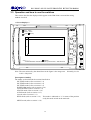
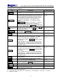
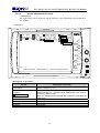
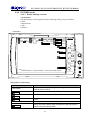
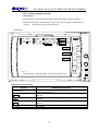
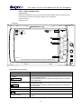
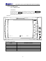
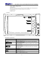
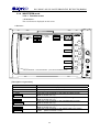
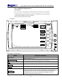
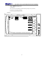
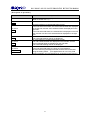
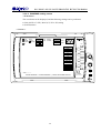
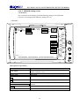
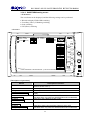
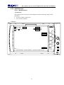
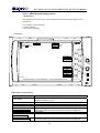
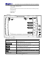
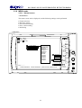
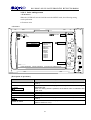
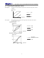
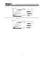
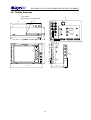
WM-3004HD
HD LCD Waveform Monitor
Instruction Manual
August 25, 2003
Ver.1.00
ASTRODESIGN, Inc.
WM-3004-HD HD LCD WAVEFORM MONITOR INSTRUCTION MANUAL
CONTENTS
INTRODUCTION・・・・・・・・・・・・・・・・・・・・・・・・・・・・・・・・・・・・・・・・・・・・・・・・・・・・・・・・・・・・・・・・・・3
SAFETY PRECAUTIONS ・・・・・・・・・・・・・・・・・・・・・・・・・・・・・・・・・・・・・・・・・・・・・・・・・・・・・・・・・・・4
CHAPTER 1
CONCERNING THE WM-3004 ・・・・・・・・・・・・・・・・・・・・・・・・・・・・・・・・・・・・・・・・・7
CHAPTER 2
PARTS AND THEIR FUNCTIONS ・・・・・・・・・・・・・・・・・・・・・・・・・・・・・・・・・・・・・・・8
2.1 WM-3004 front panel view and parts ・・・・・・・・・・・・・・・・・・・・・・・・・・・・・・・・・8
2.2 WM-3004 rear panel view and parts ・・・・・・・・・・・・・・・・・・・・・・・・・・・・・・・・・10
CHAPTER 3
OPERATION ・・・・・・・・・・・・・・・・・・・・・・・・・・・・・・・・・・・・・・・・・・・・・・・・・・・・・・・12
3.1 Connections・・・・・・・・・・・・・・・・・・・・・・・・・・・・・・・・・・・・・・・・・・・・・・・・・・・・12
3.2 Usage ・・・・・・・・・・・・・・・・・・・・・・・・・・・・・・・・・・・・・・・・・・・・・・・・・・・・・・・・・12
3.3 Operation and how to use the switches ・・・・・・・・・・・・・・・・・・・・・・・・・・・・・・・13
3.3.2 PICTURE2 mode ・・・・・・・・・・・・・・・・・・・・・・・・・・・・・・・・・・・・・・・・・21
3.3.3 PICTURE3 mode ・・・・・・・・・・・・・・・・・・・・・・・・・・・・・・・・・・・・・・・・・24
3.3.4 WAVEFORM mode ・・・・・・・・・・・・・・・・・・・・・・・・・・・・・・・・・・・・・・・26
3.3.5 VECTOR mode ・・・・・・・・・・・・・・・・・・・・・・・・・・・・・・・・・・・・・・・・・・36
3.3.6 STATUS mode ・・・・・・・・・・・・・・・・・・・・・・・・・・・・・・・・・・・・・・・・・・・41
3.3.7 AUDIO mode・・・・・・・・・・・・・・・・・・・・・・・・・・・・・・・・・・・・・・・・・・・・44
3.3.8 MENU mode ・・・・・・・・・・・・・・・・・・・・・・・・・・・・・・・・・・・・・・・・・・・・47
3.3.9 HELP mode ・・・・・・・・・・・・・・・・・・・・・・・・・・・・・・・・・・・・・・・・・・・・・50
3.4 Installing and securing the monitor ・・・・・・・・・・・・・・・・・・・・・・・・・・・・・・・・・・50
CHAPTER 4
MAIN SPECIFICATIONS ・・・・・・・・・・・・・・・・・・・・・・・・・・・・・・・・・・・・・・・・・・・・・51
4.1 Input formats ・・・・・・・・・・・・・・・・・・・・・・・・・・・・・・・・・・・・・・・・・・・・・・・・・・・51
4.2 Input signal systems ・・・・・・・・・・・・・・・・・・・・・・・・・・・・・・・・・・・・・・・・・・・・・52
4.3 Display system ・・・・・・・・・・・・・・・・・・・・・・・・・・・・・・・・・・・・・・・・・・・・・・・・・52
4.4 Headphones output ・・・・・・・・・・・・・・・・・・・・・・・・・・・・・・・・・・・・・・・・・・・・・・52
4.5 Concerning the adjustment values・・・・・・・・・・・・・・・・・・・・・・・・・・・・・・・・・・・53
4.6 Settings at initialization ・・・・・・・・・・・・・・・・・・・・・・・・・・・・・・・・・・・・・・・・・・・55
4.6.1 Common setting items ・・・・・・・・・・・・・・・・・・・・・・・・・・・・・・・・・・・・・・ 55
4.6.2 Setting items by channel ・・・・・・・・・・・・・・・・・・・・・・・・・・・・・・・・・・・・・ 56
4.7 General specifications ・・・・・・・・・・・・・・・・・・・・・・・・・・・・・・・・・・・・・・・・・・・・56
4.8 Outline drawings ・・・・・・・・・・・・・・・・・・・・・・・・・・・・・・・・・・・・・・・・・・・・・・・・57
CHAPTER 5
STANDARD AND OPTIONAL ACCESSORIES ・・・・・・・・・・・・・・・・・・・・・・・・・・・58
5.1 Standard accessories ・・・・・・・・・・・・・・・・・・・・・・・・・・・・・・・・・・・・・・・・・・・・・58
5.2 Optional accessories ・・・・・・・・・・・・・・・・・・・・・・・・・・・・・・・・・・・・・・・・・・・・・58
NOTICE ・・・・・・・・・・・・・・・・・・・・・・・・・・・・・・・・・・・・・・・・・・・・・・・・・・・・・・・・・・・・・・・・・・・・・・・・59
2
WM-3004-HD HD LCD WAVEFORM MONITOR INSTRUCTION MANUAL
INTRODUCTION
Thank you very much for purchasing this model WM-3004 HD LCD waveform monitor. This
manual contains details on the operation procedures to be followed when the WM-3004 is used, the
checkpoints and precautions to be observed, and so on.
Improper handling may result in malfunctioning. Before using the WM-3004, please read through
these instructions to ensure that you will operate the monitor correctly.
After reading through the manual, keep it in a safe place for future reference.
3
WM-3004-HD HD LCD WAVEFORM MONITOR INSTRUCTION MANUAL
SAFETY PRECAUTIONS
WARNING
Concerning the monitor
Do not subject the monitor to strong shocks or throw it around. Doing so may cause the liquid
crystal to leak and/or the monitor to malfunction, rupture, generate heat and cause a fire.
Do not use the monitor wherever there is a risk of ignition or explosions.
Do not place the monitor inside a microwave oven or other heating or cooking appliance or
pressure vessel. Doing so may cause heat or smoke to be generated in the monitor, combustion
and/or damage to the circuit components.
Inside the monitor are some high-voltage parts: since exposure to these parts may result in electric
shocks or burns, refrain from disassembling, repairing or remodeling the monitor.
If a thunderstorm should occur while the monitor is being used outdoors, immediately turn off its
power, disconnect the power cable and battery from the main unit, and move the monitor to a safe
place.
Concerning the power cord
Always take hold of the molded part of the plug when disconnecting the power cord.
Do not apply force to bend the power cord or bunch it up for use.
Do not place heavy objects on top of the power cord.
or electrical shock.
This may cause a fire.
This may damage the cord, causing a fire
Concerning foreign matter
Do not spill liquids inside the monitor or drop inflammable objects or metal parts into it.
Operating the monitor under these conditions may cause a fire, electric shocks and/or
malfunctioning.
4
WM-3004-HD HD LCD WAVEFORM MONITOR INSTRUCTION MANUAL
CAUTION
Concerning the power supply
Use a supply voltage within the range of 10V-18V DC for the monitor.
Do not turn the power back on immediately after having turned it off.
malfunctioning.
Doing so can cause
Concerning the liquid crystal
Due to the nature of liquid crystal, some picture elements may be missing (bright spots, dark spots,
etc.) at times.
Do not touch any liquid crystal which has leaked from the liquid crystal panel.
If the liquid crystal panel has been damaged by mistake and the liquid (liquid crystal) inside has
leaked out, keep the liquid away from your mouth and skin and do not inhale its odors.
In the event that liquid crystal has made contact with your eyes or mouth, use water to rinse it off
immediately. If it has come into contact with your skin or clothing, wipe it off immediately with
alcohol, and then rinse it off with soap. Leaving it in place may damage your skin or clothing.
Exercise care with the glass of a broken liquid crystal panel. If the panel has broken, be careful
not to cut your hands on the glass shards. If you should touch an area where the glass has broken
off, you may injure yourself.
The LCD panel is a high-precision component and, as such, the following care must be taken in its
handling.
1) Wiping the panel's surface with benzine, paint thinners, etc. will cause a deterioration in its
quality.
2) If water (salty water) is left on the display surface, discoloration and staining will result.
3) Exposing the panel directly to ultraviolet rays for an extended period causes the deflection
panel to turn brown, in turn causing the contrast to drop and other forms of deterioration to
develop in the display quality.
4) Moisture inside the monitor due to condensation, etc. may cause unevenness in the colors.
5) Directly tapping the surface or bumping it into objects may crack the panel, etc.
6) Do not attempt to disassemble the panel since leaking liquid crystal may make contact with
your skin, which is hazardous.
Handle the liquid crystal protective panel carefully.
Gently wipe off any fingerprints or dirt on the liquid crystal protective panel with a cleaning agent
used to clean office automation equipment. Rubbing the panel with too much force may mark or
damage the panel.
Concerning impact
This is a precision instrument and, as such, subjecting it to impact may cause malfunctioning.
Take special care when moving the monitor.
Do not drop the monitor.
5
WM-3004-HD HD LCD WAVEFORM MONITOR INSTRUCTION MANUAL
Concerning installation and operation locations
Installing the monitor in the following kinds of locations may cause malfunctioning and/or
accidents.
1) Locations with an ambient temperature outside the range of 0 -40 degrees Celsius (see Note 1)
2) Locations with an ambient humidity outside the range of 30-80% RH
3) Locations in the vicinity of an air conditioner or subject to rapid temperature changes or the
formation of condensation
4) Locations exposed to direct sunlight (see Note 2)
5) Locations exposed to corrosive gases or high concentrations of dust
6) Locations where strong magnetic fields are generated
7) Locations where the monitor may be splashed with water, oil, chemicals, etc.
8) Locations to which vibrations are transmitted from the floor
9) Unstable locations
Take good care to meet the following conditions in order to ensure that the monitor will be used
properly.
1) Do not place heavy objects such as another monitor directly on top of the monitor.
2) Avoid placing any objects around the monitor.
Note 1: When the surface temperature of the LCD panel exceeds 60 degrees Celsius, the
panel's backlight and other parts may be damaged.
Note 2: Exposing the panel directly to ultraviolet rays for an extended period causes the
deflection panel to turn brown, in turn causing the contrast to drop and other forms of
deterioration to develop in the display quality.
When the monitor fails to operate properly
When the image is not displayed properly, check the format settings.
If
NoSignal appears on the screen even though input signals have been supplied, check the
input settings and the format settings.
If the front panel switches should fail to operate, check whether the LOCK switch is at the ON
position.
When trouble or malfunctioning occurs
In the unlikely event that trouble or malfunctioning should occur, contact your dealer or an
Astrodesign sales representative.
If trouble should occur in the LCD panel, the user will be charged for repairs and parts
replacement even within the warranty period.
Concerning this manual
It is strictly forbidden to copy this manual either in part or in its entirety without permission from
Astrodesign.
1) The contents and specifications of this manual are subject to change without notice for the
purposes of improving quality.
2) Although this manual has been prepared with painstaking care, the user is asked to contact
Astrodesign if any ambiguities, mistakes, omissions or other shortcomings are noticed.
6
WM-3004-HD HD LCD WAVEFORM MONITOR INSTRUCTION MANUAL
CHAPTER 1
CONCERNING THE WM-3004
The WM-3004 is a compact, lightweight and portable LCD waveform monitor which comes in handy
for monitoring the pictures being shot during live broadcasts, on location or in studios, etc.
The camera battery is supported as the power supply so that pictures, waveforms and sound can be
checked even in locations where difficulties have been encountered in the past in carrying in
equipment.
A full range of functions is provided including functions for adjusting the brightness, contrast and
chroma levels as well as functions for displaying markers.
Input signals in a total of 23 HDTV video formats are supported.
1.1 Outline of WM-3004
6.4-inch a-Si TFT LCD panel featured
HD-SDI or YPbPr HD analog input signals (Y-on-sync) supported
23 different video formats supported
Standards supporting HD-SDI: SMPTE 292M, BTA-S004B standards complied with (1.485
Gbps SDI input)
Standards for analog input and supported formats: SMPTE 274M, SMPTE 296M,
BTA-S001B standards complied with
SDI IN (×2), SDI MONITOR OUT, HD analog input (ANALOG Y, ANALOG Pb,
ANALOG Pr) and REF IN connectors provided
Brightness, contrast, chroma, filter, monochrome, Y gamma adjustment functions
Marker display functions (frame, center, 4:3, 13:9, 14:9, 2.35:1, 1.85:1, 1.66:1)
Single-action operation of input channels, partial display/non-display of information, picture
overlay and freeze/update selection using the switches on the front panel
Lighting of red, green LEDs at top of screen by external contact supply-type tally inputs
Automatic scanning of input signals possible
Automatic 1/1.000 and 1/1.001 frame rate scanning and input signal detection functions
CRC error detection function (during HD-SDI input) for input channels
Functions for locking the panel switches and storing the setting values
Light weight and compact size
DC supply power input (10-18V)
Camera battery supported
7
WM-3004-HD HD LCD WAVEFORM MONITOR INSTRUCTION MANUAL
CHAPTER 2
PARTS AND THEIR FUNCTIONS
2.1 WM-3004 front panel view and parts
WM-3004 front panel view
<7>
<8>
<9>
<10>
)
INPUT
<11>
<16>
F1
DISPLAY
<12>
<17>)
F2
PICTURE1
OVERLAY
<13>
<18>
2
3
MENU
1
F3
AUDIO
STATUS
VECTOR
WAVE
FREEZE
<14>
<19>
<4>
<5>
F4
FUNC
<15>
<20>
<3>
2
LOCK
F5
<2>
OFF
ON
WM-3004
HD LCD
WAVEFORM MONITOR
POWER
○
|
<1>
<6>
<10>
8
WM-3004-HD HD LCD WAVEFORM MONITOR INSTRUCTION MANUAL
Front panel parts and their functions
Number
Part
<1>
Power switch/LED
<2>
LOCK switch/LED
<3>
Mode switch
<4>
<5>
<6>
<7>
Adjustment dial
Setting switch
Headphone jack
Liquid crystal display
<8>
TALLY 1
<9>
TALLY 2
<10>
1/4-20UNC threaded
hole
<11>
INPUT switch
<12>
DISPLAY switch
<13>
OVERLAY switch
<14>
FREEZE switch
<15>
FUNC switch
<16>
F1 switch
<17>
F2 switch
<18>
F3 switch
<19>
F4 switch
<20>
F5 switch
Description of function
This switch is used to turn the power ON and OFF. (Its LED
lights up green while the power is supplied.)
This switch is used to lock the panel switches and save the
Wait appears at the
setting values simultaneously.
bottom right of the screen while the settings are being saved,
and upon completion of the saving process, PANEL LOCK
appears. Do not turn off the power while the setting saving
process is in progress.
The saved settings are loaded when the power is turned on.
(The LED of this switch lights up yellow while the panel
switches are locked.)
This switch is used to select the monitor's mode. The mode is
selected in the following sequence:
PICTURE1
PICTURE2
PICTURE3
WAVEFORM
MENU
1
2
AUDIO
STATUS
VECTOR
This dial is used to adjust and select the settings.
This switch is used to adjust and select the settings.
The sound is output from this jack (diameter: 35 mm).
The images appear on this display.
Tally lamp (red): this is controlled by the rear panel tally
connector (contact supply type).
Tally lamp (green): this is controlled by the rear panel tally
connector (contact supply type).
Threaded hole for a screw to anchor the monitor (used to
anchor the monitor to a tripod, arm, etc.).
This switch is used to select SDI A or SDI B for the input
signals. When it is held down (for more than one second),
analog signals are input.
This switch is used to set whether the information is to be
partially displayed on the screen or not displayed at all. When
it is held down (for more than one second), the top and bottom
of the screen are inverted.
This switch is used to change the picture overlay settings.
When it is held down (for more than one second), the color
setting screen appears. (The color setting items differ
according to the mode selected.)
This switch is used to select freeze or update.
Freeze is released by switching the input signals or format.
Bear in mind that if the input signals are cut off or their format
has been changed in the freeze status, the correct data will not
be output.
This switch is used to select the function switches (switches F1
to F5).
The function of this switch is different depending on each menu
which is selected.
The function of this switch is different depending on each menu
which is selected.
The function of this switch is different depending on each menu
which is selected.
The function of this switch is different depending on each menu
which is selected.
The function of this switch is different depending on each menu
which is selected.
9
WM-3004-HD HD LCD WAVEFORM MONITOR INSTRUCTION MANUAL
2.2 WM-3004 rear panel view and parts
WM-3004 rear panel view
<4> <5> <6>
<2>
<3>
<7>
<9>
<1>
<10>
<8>
Names of rear panel parts
Number
<1>
<2>
<3>
<4>
<5>
<6>
<7>
<8>
<9>
<10>
Part
Description of function
Cannon connector, DC power input socket (GND: pin 1; DC IN:
Power socket (*1)
pin 4).
SDI IN Ach
HD-SDI signal input connector.
SDI IN Bch
HD-SDI signal input connector.
HD analog Y signal input connector; synchronization is provided
Y IN
by the Y signal in the case of analog inputs.
Pb IN
HD analog Pb (Cb) signal input connector.
Pr IN
HD analog Pr (Cr) signal input connector.
Output connector for simplified monitoring of SDI input
signals.SDI A
MONITOR OUT
SDI A images are output when the SDI A input is selected.
SDI B images are output when the SDI B input is selected.
SDI A images are output when the analog input is selected.
REF IN
Reference input signal connector (HD tri-level sync only).
TALLY connector (*2) D-sub 9-pin (female)
This is used to enable or disable the 75Ω termination for the analog
Termination selector
signals.
switch (*3)
10
WM-3004-HD HD LCD WAVEFORM MONITOR INSTRUCTION MANUAL
*1: Power socket (no. <1>)
1
4
2
Pin No.
1
2
3
4
Function
GND
NC
NC
DC IN (10-18V)
Pin No.
1
2
3
4
5
6
7
8
9
Function
GND
TALLY2 (green)
NC (reserved) (Note)
NC (reserved) (Note)
NC (reserved) (Note)
GND
TALLY1 (red)
NC (reserved) (Note)
GND
3
*2: TALLY connector (no. <9>)
1
5
6
9
When GND and pin 2 are shorted, the green tally lamp lights; when GND and pin 7 are shorted, the
red tally lamp lights.
(Note) Do not connect anything to the pins marked NC (reserved).
malfunctioning.
Doing so may cause
*3: Termination selector switch (no. <10>)
Switch
Y
PB
75Ω PR
HIGH
Y
PB
PR
Left
Y 75Ω termination
PB 75Ω termination
PR 75Ω termination
Setting
Right
No Y termination
No PB termination
No PR termination
As shown in the figure above, the initial setting positions starting with the top one first are left (Y 75Ω
termination), left (Pb 75Ω termination) and left (Pr 75Ω termination).
11
WM-3004-HD HD LCD WAVEFORM MONITOR INSTRUCTION MANUAL
CHAPTER 3
OPERATION
3.1 Connections
This section describes how to connect the WM-3004.
(1) Connecting the power supply
Connect the Cannon connector of the AC/DC adapter to the WM-3004's power socket.
Check the shape of the connector and socket before use.
(2) Connecting the input signals
When SDI signals are to be input:
When SDI signals are to be input, use BNC coaxial cables to make the connections to
the SDI IN connectors.
The SDI IN connectors are where the SDI signals are input; MONITOR OUT is an
output connector which is used for the simplified monitoring of the SDI input signals.
Supply serial input signals complying with the BTA S-004B standard as the HD-SDI
input signals. Use a coaxial cable (5C-FB or its equivalent) which can handle the 1.5
GHz band.
When analog signals are to be input:
When HD analog signals are to be input, input the YPbPr signals to the respective
analog connectors.
Input YPbPr signals complying with the BTA S-001B standard as the HD analog input
signals.
Synchronization is obtained from the Y signal.
• Precaution to be observed in the WAVEFORM or VECTOR mode:
When the waveforms or vectors of analog signals are to be displayed, noise with a
maximum level of ±30mV may occur inside the WM-3004. Therefore, do not use
the monitor for measurements requiring a higher precision.
• Precaution to be observed in the STATUS mode:
Since the WM-3004 employs an 8-bit A/D converter, 00 is always output for the
lower 2 bits of the 10 bits displayed in the STATUS mode.
3.2 Usage
A protective film is attached to the surface of the LCD panel.
WM-3004.
Peel it off before using the
After checking the connections, turn on the power of the WM-3004 using the POWER switch
on the front panel. The POWER LED lights, and images are displayed.
If the POWER LED fails to light, check the connections again.
To conduct the simplified monitoring of the SDI input signals, use the MONITOR OUT
connector.
The analog input signals will not appear on the monitor if no sync signals are contained in the Y
signal. Check the ARIB BTA S-001 and other standards for the levels, etc.
If no input signals are supplied, the image area appears all black, and
displayed on the screen.
12
NoSignal
is
WM-3004-HD HD LCD WAVEFORM MONITOR INSTRUCTION MANUAL
3.3 Operation and how to use the switches
This section describes the displays which appear on the WM-3004 screen and the setting
methods involved.
<<Screen displays>>
Input
SDI A
Format AUTO
60.00)
(1080i
Int
INPUT
960
F1
DISPLAY
F2
PICTURE 1
OVERLAY
2
3
MENU
1
540
F3
2
AUDIO
STATUS
VECTOR
FREEZE
WAVE
F4
FUNC
LOCK
F5
OFF
ON
VITC:--:--:--:--
NoSignal
YCRCE:000000000 PCRCE:000000000 (LAST:00:00:00/TIME:00:00:00)
WM-3004
HD LCD
WAVEFORM MONITOR
POWER
○
|
Note: The area enclosed by the dotted lines in the figure is the image area.
is 960 × 540 pixels.
Normally, its size
[Description of modes]
The modes are described in the sections listed below.
PICTURE1 mode (refer to section 3.3.1)
PICTURE2 mode (refer to section 3.3.2)
PICTURE3 mode (refer to section 3.3.3)
WAVEFORM mode (refer to section 3.3.4)
VECTOR mode (refer to section 3.3.5)
STATUS mode (refer to section 3.3.6)
AUDIO mode (refer to section 3.3.7)
2 mode (refer to section 3.3.3)
HELP mode (refer to section 3.3.9) This mode is indicated as "1" in terms of the position
set by the mode switch on the main unit.
MENU mode (refer to section 3.3.8)
13
WM-3004-HD HD LCD WAVEFORM MONITOR INSTRUCTION MANUAL
[Description of screen displays]
Item
Input
Format
(Reference)
NoSignal
VITC
YCRCE
PCRCE
LAST
TIME
Freeze
Filter
Mono
FRC
Description
Displayed here is the input channel (SDI A, SDI B or
Analog) which has been selected by the INPUT switch.
The selected format is displayed here.
Indicated within the parentheses on the line below are
the input signal format and field (or frame) frequency.
When analog input has been selected even if 1035
input signals are supplied, these signals will be
identified as 1080 signals. If no signals are input
(when
NoSignal appears on the screen), "*" appears.
(For details on the formats, refer to Chapter 4.)
If the format which has been set and the format of the
actual input signals differ,
Format appears in red.
The input reference signal is displayed here. Int
denotes an internal sync signal; Ref denotes an
external sync signal.
If the signal which has been set and the actual input
signals differ,
NoSignal appears in red.
The time code (VITC) is displayed here.
This is where the Y signal is checked for CRC errors
and the number of errors is displayed. The CRC
errors are counted even in the freeze status.
When an error is found, YCRCE appears in red for
one second.
Note: The CRC errors are not counted when analog
signals are input. Neither are they counted for one
second after the input signals have been changed by
the INPUT switch.
This is where the Pb and Pr signals are checked for
CRC errors and the number of errors is displayed.
The CRC errors are counted even in the freeze status.
When an error is found, PCRCE appears in red for
one second.
Note: The CRC errors are not counted when analog
signals are input. Neither are they counted for one
second after the input signals have been changed by
the INPUT switch.
The time elapsed since the last error was found is
displayed here.
The time elapsing after the WM-3004 was started or
error count was reset is displayed here.
This indicates the freeze status. When the freeze
status is established, Freeze appears in blue.
This indicates whether the video filter is ON or OFF.
This indicates whether monochrome is ON or OFF.
This indicates whether the 8-bit processing using the
frame rate control is ON or OFF.
Display modes
P1・P2・W・V・S・
A・M
P1・P2・W・V・S・
A・M
P1・P2・W・V・S・
A・M
P1・P2・P3・W・V・
S・A・M
P1・P2・P3・W・V・
S・A・M
P1・P2・W・V・S・
A・M
P1・P2・W・V・S・
A・M
P1・P2・W・V・S・
A・M
P1・P2・W・V・S・
A・M
P1・P2・P3・W・V・
S・A・M
P1・P2
P1・P2
P1・P2
Abbreviations used in display mode column:
P1・・・PICTURE1, P2・・・PICTURE2, P3・・・PICTURE3, W・・・WAVEFORM, V・・・VECTOR, S・・・STATUS,
A・・・AUDIO, M・・・MENU
14
WM-3004-HD HD LCD WAVEFORM MONITOR INSTRUCTION MANUAL
Item
G
B
R
(Marker)
Y-Gamma
Bright
Contrast
Pb(Cb)
Pr(Cr)
YPbPr / GBR
Parade / Overlay
1H / 2H / 1F / 2F
M x1 / x2 / x4
G x*.**
dT
d% / dV
Field 1 / Field 2
Line (Field)
Line (Frame)
Sample
x 1.00
Volume
L:xCH R:xCH
Information
Marker
Scale
Waveform
Cursor
Vector
Status
Description
This indicates whether the input video green (G) signal
is to be displayed.
This indicates whether the input video blue (B) signal is
to be displayed.
This indicates whether the input video red (R) signal is
to be displayed.
This indicates a list of the usable markers. The
currently selected marker is highlighted.
This indicates the Y gamma setting.
This indicates the brightness setting.
This indicates the contrast setting.
This indicates the Pb (Cb) setting.
This indicates the Pr (Cr) setting.
This indicates the waveform display method.
This indicates the parade display or overlay display for
the waveforms.
This indicates the sweep 1H/2H/1F/2F switching.
This indicates the MAG magnification rate.
This indicates the GAIN magnification rate.
This indicates the H cursor difference. It does not
appear unless the H cursor is displayed.
This indicates the V cursor difference. It does not
appear unless the V cursor is displayed.
This indicates the currently displayed field. It does not
appear unless LineSelect is set to ON.
This indicates the line number in the currently displayed
field. It does not appear unless LineSelect is set to
ON.
This indicates the line number. It does not appear
unless LineSelect is set to ON.
This indicates the sample number.
This indicates the GAIN magnification rate.
This indicates the position of the displayed waveform.
This indicates the volume level.
This indicates the embedded audio channels through
which the sound is output.
This indicates the color of the characters.
This indicates the color of the markers.
This indicates the color of the scale.
This indicates the color and brightness of the
waveforms.
This indicates the color of the cursors.
This indicates the color and brightness of the vectors.
This indicates the color of the status.
Display modes
P1・P2
P1・P2
P1・P2
P1・P2
P1・P2
P1・P2
P1・P2
P1・P2
P1・P2
W
W
W
W
W
W
W
W・V・S
W・V・S
W・V・S
S
V
W
A
A
P1・P2・P3・W・V・
S・A・M
P1・P2・P3
W・V・S・A
W
W・V・S
V
S・A
Abbreviations used in display mode column:
P1・・・PICTURE1, P2・・・PICTURE2, P3・・・PICTURE3, W・・・WAVEFORM, V・・・VECTOR, S・・・STATUS,
A・・・AUDIO, M・・・MENU
15
WM-3004-HD HD LCD WAVEFORM MONITOR INSTRUCTION MANUAL
[Description of operations]
Switch
INPUT switch
DISPLAY switch
OVERLAY switch
FREEZE switch
FUNC switch
LOCK switch
Description of function
This switch is used to select the SDI A or SDI B input signals. When
it is held down (for more than one second), analog signals are input.
If the freeze status is established at this time, it is released.
This switch is used to set whether the information is to be partially
displayed on the screen or not displayed at all. When it is held down
(for more than one second), the top and bottom of the screen are
inverted.
This switch is used to perform the picture overlay settings. In the
PICTURE1, PICTURE2 or PICTURE3 mode, it has no effect since a
picture is always displayed. When it is held down (for more than 1
second), the color setting screen appears. (The color setting items
differ according to the mode selected.)
This switch is used to select freeze or update.
Freeze is released by switching the input signals or format. Bear in
mind that if the input signals are cut off or their format has been
changed in the freeze status, the correct data will not be output.
CRC errors are counted even while the freeze status is established.
This switch is used to select the function switches (switches F1 to F5).
All key operations are canceled, and the values for the setting items in
Wait appears at the bottom right of the
section 4.6 are saved.
screen while the settings are being saved, and upon completion of the
saving process, PANEL LOCK appears. Do not turn off the power
while the setting saving process is in progress.
The saved settings are loaded and established when the power is
turned on.
16
WM-3004-HD HD LCD WAVEFORM MONITOR INSTRUCTION MANUAL
3.3.1 PICTURE1 mode
3.3.1.1 Picture adjustments 1 screen
<<Functions>>
The input images can be displayed, and the following video adjustments can be
undertaken.
•
•
•
•
•
Brightness
Contrast
Chroma
Pb (Cb)
Pr (Cr)
<<Screen>>
17
WM-3004-HD HD LCD WAVEFORM MONITOR INSTRUCTION MANUAL
Input
SDI A
Filter ON
Format AUTO
Mono
OFF
60.00) FRC
OFF
(1080i
G
B
R
Int
FRAME CENTER
4:3
13:9
14:9
2.35:1 1.85:1 1.66:1
Y-Gamma
1.000
Bright
0.00%
Contrast 100.0%
Pb(Cb)
100.0%
Pr(Cr)
100.0%
INPUT
F1
Bright
DISPLAY
F2
PICTURE 1
Contrast
2
3
MENU
OVERLA
Y
1
2
F3
AUDIO
STATUS
VECTOR
Chroma
WAVE
FREEZE
F4
Pb(Cb)
FUNC
LOCK
F5
ON
Pr(Cr)
VITC:--:--:--:-YCRCE:000000000
WM-3004
PCRCE:000000000
18
(LAST:00:00:00/TIME:00:00:00)
OFF
HD LCD
WAVEFORM MONITOR
POWER
○
|
WM-3004-HD HD LCD WAVEFORM MONITOR INSTRUCTION MANUAL
[Description of operations]
Switch
FUNC switch
F1 switch
Bright
F2 switch
Contrast
F3 switch
Chroma
F4 switch
Pb(Cb)
F5 switch
Pr(Cr)
Description of function
This switches the display to the picture adjustment 2 screen.
(Refer to section 3.3.1.2)
Press this to adjust the brightness using the adjustment dial.
Refer to section 4.5. (Variable range: -50.00% to +50.00%)
Press this to adjust the contrast using the adjustment dial.
(Variable range: 0.0%-200.0%)
When the setting switch is pressed, the contrast is restored to the
initial value.
Press this to adjust the chroma value using the adjustment dial.
(Variable range: 0.0%-200.0%)
When the setting switch is pressed, the chroma is restored to the initial
value.
Press this to adjust the Pb (Cb) value using the adjustment dial.
(Variable range: 0.0%-200.0%)
When the setting switch is pressed, Pb (Cb) is restored to the initial
value.
Press this to adjust the Pr (Cr) value using the adjustment dial.
(Variable range: 0.0%-200.0%)
When the setting switch is pressed, Pr (Cr) is restored to the initial
value.
19
WM-3004-HD HD LCD WAVEFORM MONITOR INSTRUCTION MANUAL
3.3.1.2
Picture adjustments 2 screen
<<Functions>>
The input images can be displayed, and the following video adjustment can be undertaken.
• Y gamma
<<Screen>>
Input
SDI A
Format AUTO
(1080i
60.00)
Int
Filter ON
Mono
OFF
FRC
OFF
G
B
R
FRAME CENTER
4:3
13:9
14:9
2.35:1 1.85:1 1.66:1
Y-Gamma
1.000
Bright
0.00%
Contrast 100.0%
Pb(Cb)
100.0%
Pr(Cr)
100.0%
Gamma/Effect
INPUT
F1
DISPLAY
F2
PICTURE 1
OVERLAY
2
3
MENU
1
2
F3
AUDIO
STATUS
VECTOR
WAVE
FREEZE
F4
FUNC
LOCK
F5
OFF
ON
VITC:--:--:--:-YCRCE:000000000
PCRCE:000000000
(LAST:00:00:00/TIME:00:00:00)
WM-3004
HD LCD
WAVEFORM MONITOR
POWER
○
|
[Description of operations]
Switch
FUNC switch
F1 switch
Gamma/Effect
F2 switch
F3 switch
F4 switch
F5 switch
Description of function
This switches the display to the picture adjustment 1 screen.
(Refer to section 3.3.1.1)
Press this to adjust the Y gamma value using the adjustment dial.
Refer to section 4.5. (Variable range: 0.500-2.000; when 2.000 is
exceeded, "Effect" is set.)
When the setting switch is pressed, the Y gamma is restored to the
initial value.
(Not used)
(Not used)
(Not used)
(Not used)
20
WM-3004-HD HD LCD WAVEFORM MONITOR INSTRUCTION MANUAL
3.3.1.3 Color setting screen
<<Functions>>
When the OVERLAY switch is held down in the PICTURE1 mode, the input images
can be displayed, and the following settings can be performed.
• Character color
• Marker color
<< screen>>
Information
Marker
Input
SDI A
Format AUTO
60.00)
(1080i
Int
White3
White3
INPUT
F1
Information
DISPLAY
F2
PICTURE 1
Marker
OVERLAY
2
3
MENU
1
2
F3
AUDIO
STATUS
VECTOR
WAVE
FREEZE
F4
FUNC
LOCK
F5
Exit
VITC:--:--:--:-YCRCE:000000000
OFF
ON
POWER
WM-3004
PCRCE:000000000
(LAST:00:00:00/TIME:00:00:00)
HD LCD
WAVEFORM MONITOR
○
|
[Description of operations]
Switch
FUNC switch
F1 switch
Information
F2 switch
Marker
F3 switch
F4 switch
F5 switch
Exit
OVERLAY switch
Description of function
Press this to return the display to the previous screen.
Press this to select the color (any of 63 colors) of the characters
using the adjustment dial.
When the setting switch is pressed, the character color is restored
to the initial value.
Press this to select the color (any of 64 colors) of the markers using
the adjustment dial.
When the setting switch is pressed, the marker color is restored to
the initial value.
(Not used)
(Not used)
Press this to return the display to the previous screen.
When this is held down, the display is returned to the previous
screen.
21
WM-3004-HD HD LCD WAVEFORM MONITOR INSTRUCTION MANUAL
22
WM-3004-HD HD LCD WAVEFORM MONITOR INSTRUCTION MANUAL
3.3.2 PICTURE2 mode
3.3.2.1 Picture settings 1 screen
<<Functions>>
The input images can be displayed, and the following settings can be performed.
• Filter
• Monochrome
• FRC
• Markers
<<Screen>>
Input
SDI A
Format AUTO
60.00)
(1080i
Int
Filter ON
Mono
OFF
FRC
OFF
G
B
R
FRAME CENTER
4:3
13:9
14:9
2.35:1 1.85:1 1.66:1
Y-Gamma
1.000
Bright
0.00%
Contrast 100.0%
Pb(Cb)
100.0%
Pr(Cr)
100.0%
Filter
INPUT
F1
DISPLAY
Mono
F2
PICTURE 1
OVERLAY
2
3
MENU
1
FRC
2
F3
AUDIO
STATUS
VECTOR
WAVE
FREEZE
F4
FUNC
LOCK
Marker
VITC:--:--:--:-YCRCE:000000000
PCRCE:000000000
(LAST:00:00:00/TIME:00:00:00)
F5
OFF
ON
POWER
WM-3004
HD LCD
WAVEFORM MONITOR
○
|
[Description of operations]
Switch
FUNC switch
F1 switch
Filter
F2 switch
Mono
F3 switch
FRC
F4 switch
F5 switch
Marker
Description of function
This switches the display to the picture settings 2 screen.
(Refer to section 3.3.2.2)
Press this to set the filter to ON or OFF.
Press this to set monochrome to ON or OFF.
Press this to set the 8-bit processing using frame rate control to ON
or OFF.
(Not used)
Press this to set the markers to ON or OFF. At the marker ON
setting, select the markers using the adjustment dial and enter the
selection using the setting switch
23
WM-3004-HD HD LCD WAVEFORM MONITOR INSTRUCTION MANUAL
3.3.2.2 Picture settings 2 screen
<<Functions>>
The input images can be displayed, and the following settings can be performed.
• Selection of display or non-display for green, blue and red signals of the displayed
pictures. (This affects only the picture display.)
<<Screen>>
Input
SDI A
Format AUTO
60.00)
(1080i
Int
Filter ON
Mono
OFF
FRC
OFF
G
B
R
FRAME CENTER
4:3
13:9
14:9
2.35:1 1.85:1 1.66:1
Y-Gamma
1.000
Bright
0.00%
Contrast 100.0%
Pb(Cb)
100.0%
Pr(Cr)
100.0%
INPUT
F1
Green
DISPLAY
Blue
F2
PICTURE 1
OVERLAY
2
3
MENU
1
2
Red
F3
AUDIO
STATUS
VECTOR
WAVE
FREEZE
F4
FUNC
LOCK
F5
OFF
ON
VITC:--:--:--:-YCRCE:000000000
PCRCE:000000000
(LAST:00:00:00/TIME:00:00:00)
POWER
WM-3004
HD LCD
WAVEFORM MONITOR
○
|
[Description of operations]
Switch
FUNC switch
F1 switch
Green
F2 switch
Blue
F3 switch
Red
F4 switch
F5 switch
Description of function
This switches the display to the picture settings 1 screen.
(Refer to section 3.3.2.1)
Press this to select whether to display the green signals of the input
pictures.
Press this to select whether to display the blue signals of the input
pictures.
Press this to select whether to display the red signals of the input
pictures.
(Not used)
(Not used)
24
WM-3004-HD HD LCD WAVEFORM MONITOR INSTRUCTION MANUAL
3.3.2.3 Color setting screen
<<Functions>>
When the OVERLAY switch is held down in the PICTURE2 mode, the input pictures
can be displayed, and the following settings can be performed.
• Character color
• Marker color
<<screen>>
Input
SDI A
Format AUTO
60.00)
(1080i
Int
Information
Marker
White3
White3
INPUT
F1
Information
DISPLAY
F2
PICTURE 1
Marker
OVERLAY
2
3
MENU
1
2
F3
AUDIO
STATUS
VECTOR
WAVE
FREEZE
F4
FUNC
LOCK
F5
Exit
VITC:--:--:--:--
OFF
ON
POWER
WM-3004
YCRCE:000000000 PCRCE:000000000 (LAST:00:00:00/IME:00:00:00)
HD LCD
WAVEFORM MONITOR
○
|
[Description of operations]
Switch
FUNC switch
F1 switch
Information
F2 switch
Marker
F3 switch
F4 switch
F5 switch
Exit
OVERLAY switch
Description of function
Press this to return the display to the previous screen.
Press this to select the color (any of 63 colors) of the characters
using the adjustment dial.
When the setting switch is pressed, the character color is restored
to the initial value.
Press this to select the color (any of 64 colors) of the markers using
the adjustment dial.
When the setting switch is pressed, the marker color is restored to
the initial value.
(Not used)
(Not used)
Press this to return the display to the previous screen.
When this is held down, the display is returned to the previous
screen.
25
WM-3004-HD HD LCD WAVEFORM MONITOR INSTRUCTION MANUAL
3.3.3 PICTURE3 mode
3.3.3.1 Regular screen
<<Functions>>
The input pictures are displayed, and all displays with the exception of
NoSignal ,
the time code (VITC), Freeze and the markers are cleared. Apart from
displaying the time code (VITC), the functions in the PICTURE3 mode are identical to
the PICTURE2 mode functions.
<<Screen>>
INPUT
F1
DISPLAY
F2
PICTURE 1
2
3
MENU
OVERLAY
1
2
F3
AUDIO
STATUS
VECTOR
WAVE
FREEZE
F4
FUNC
LOCK
F5
OFF
ON
VITC:--:--:--:--
NoSignal
Freeze
WM-3004
HD LCD
WAVEFORM MONITOR
[Description of operations]
Switch
FUNC switch
Adjustment dial
Setting switch
F1 switch
F2 switch
F3 switch
F4 switch
F5 switch
Description of function
(Not used)
(Not used)
(Not used)
(Not used)
(Not used)
(Not used)
(Not used)
(Not used)
26
POWER
○
|
WM-3004-HD HD LCD WAVEFORM MONITOR INSTRUCTION MANUAL
3.3.3.2 Color setting screen
<<Functions>>
When the OVERLAY switch is held down in the PICTURE3 mode, the input pictures
can be displayed, and the following settings can be performed.
• Character color
• Marker color
<<screen>>
Information
Marker
White3
White3
INPUT
Information
F1
DISPLAY
Marker
F2
PICTURE 1
2
3
MENU
OVERLAY
1
2
F3
STATUS
AUDIO
VECTOR
WAVE
FREEZE
F4
FUNC
LOCK
Exit
VITC:--:--:--:-YCRCE:000000000
PCRCE:000000000
(LAST:00:00:00/TIME:00:00:00)
F5
OFF
ON
WM-3004
HD LCD
WAVEFORM MONITOR
POWER
○
|
[Description of operations]
Switch
FUNC switch
F1 switch
Information
F2 switch
Marker
F3 switch
F4 switch
F5 switch
Exit
OVERLAY switch
Description of function
Press this to return the display to the normal screen.
(Refer to section 3.3.3.1)
Press this to select the color (any of 63 colors) of the characters
using the adjustment dial.
When the setting switch is pressed, the character color is restored
to the initial value.
Press this to select the color (any of 64 colors) of the markers using
the adjustment dial.
When the setting switch is pressed, the marker color is restored to
the initial value.
(Not used)
(Not used)
Press this to return the display to the normal screen.
(Refer to section 3.3.3.1)
When this is held down, the display is returned to the normal
screen. (Refer to section 3.3.3.1)
27
WM-3004-HD HD LCD WAVEFORM MONITOR INSTRUCTION MANUAL
3.3.4 WAVEFORM mode
3.3.4.1 Function screen
<<Functions>>
The waveforms are displayed on this screen.
<<Screen>>
Input
SDI A
Format AUTO
60.00)
(1080i
Int
YPbPr
Parade
1H Mx1
G x1.00
dT 8.00µs
d% 20.00%
Field 1
Line(Field) 0001
Line(Frame) 0001
INPUT
F1
DISPLAY
DISPLAY
F2
SWEEP
PICTURE 1
OVERLAY
2
3
MENU
1
2
F3
GAIN/MAG
AUDIO
STATUS
VECTOR
WAVE
FREEZE
F4
CURSOR
FUNC
LOCK
F5
SETTING
VITC:--:--:--:-YCRCE:000000000
PCRCE:000000000
(LAST:00:00:00/TIME:00:00:00)
OFF
ON
WM-3004
HD LCD
WAVEFORM MONITOR
POWER
○
|
[Description of operations]
Switch
FUNC switch
Adjustment dial
Setting switch
F1 switch
DISPLAY
F2 switch
SWEEP
F3 switch
GAIN/MAG
F4 switch
CURSOR
F5 switch
SETTING
Description of function
Press this to return the display to the previous screen.
(Not used)
(Not used)
Press this to set the display to the DISPLAY setting screen.
(Refer to section 3.3.4.2)
Press this to set the display to the SWEEP setting screen.
(Refer to section 3.3.4.3)
Press this to set the display to the GAIN/MA setting screen.
(Refer to section 3.3.4.4)
Press this to set the display to the CURSOR setting screen.
(Refer to section 3.3.4.5)
Press this to set the display to the WAVEFORM mode setting
screen. (Refer to section 3.3.4.6)
28
WM-3004-HD HD LCD WAVEFORM MONITOR INSTRUCTION MANUAL
3.3.4.2 DISPLAY setting screen
<<Functions>>
The waveforms can be displayed, and the following settings can be performed.
• Switching between parade display (side-by-side display) and overlay display
(superimposed display) for the waveforms
• Line select function (with 1H, 2H)
<<Screen>>
Input
SDI A
Format AUTO
(1080i
60.00)
Int
YPbPr
Parade
1H Mx1
G x1.00
dT 8.00µs
d% 20.00%
Field 1
Line(Field) 0001
Line(Frame) 0001
INPUT
F1
Parade
Overlay
DISPLAY
F2
PICTURE 1
Y
2
3
MENU
OVERLAY
1
2
F3
AUDIO
Pb(Cb)
STATUS
VECTOR
WAVE
FREEZE
F4
Pr(Cr)
FUNC
LOCK
F5
LineSelect
VITC:--:--:--:-YCRCE:000000000
OFF
ON
POWER
WM-3004
PCRCE:000000000
(LAST:00:00:00/TIME:00:00:00)
HD LCD
WAVEFORM MONITOR
○
|
[Description of operations]
Switch
FUNC switch
F1 switch
Parade/Overlay
F2 switch
Y
F3 switch
Pb(Cb)
F4 switch
Pr(Cr)
F5 switch
LineSelect
Description of function
Press this to return the display to the function screen.
(Refer to section 3.3.4.1)
Press this to switch between parade display (side-by-side display) and
overlay display (superimposed display) for the waveforms.
Press this to set Y/G to ON or OFF.
Press this to set Pb/B to ON or OFF.
Press this to set Pr/R to ON or OFF.
Press this to set line select to ON or OFF.
When line select is ON, the lines are incremented or decremented using
the adjustment dial, and the field is switched using the setting switch.
(This applies with 1H or 2H only; field switching applies only with
interlacing or segmented frame format.)
29
WM-3004-HD HD LCD WAVEFORM MONITOR INSTRUCTION MANUAL
3.3.4.3 SWEEP setting screen
<<Functions>>
The waveforms can be displayed, and the following settings can be performed.
• 1H, 2H, 1F or 2F display switching
• Line select function (with 1H or 2H)
<<Screen>>
Input
SDI A
Format AUTO
(1080i
60.00)
Int
YPbPr
Parade
1H Mx1
G x1.00
dT 8.00µs
d% 20.00%
Field 1
Line(Field) 0001
Line(Frame) 0001
INPUT
1H
F1
DISPLAY
2H
F2
PICTURE 1
OVERLAY
1F
2
3
MENU
1
2
F3
AUDIO
STATUS
VECTOR
WAVE
FREEZE
2F
F4
FUNC
LineSelect
LOCK
F5
OFF
ON
VITC:--:--:--:-YCRCE:000000000
POWER
WM-3004
PCRCE:000000000
(LAST:00:00:00/TIME:00:00:00)
HD LCD
WAVEFORM MONITOR
○
|
30
WM-3004-HD HD LCD WAVEFORM MONITOR INSTRUCTION MANUAL
[Description of operations]
Switch
FUNC switch
F1 switch
1H
F2 switch
2H
F3 switch
1F
F4 switch
2F
F5 switch
LineSelect
Description of function
Press this to return the display to the function screen.
(Refer to section 3.3.4.1)
1H
2H (with interlacing or segmented frame format)
In the line select OFF status, the odd-numbered fields are displayed
on the left side, and the even-numbered fields are displayed on the
right side.
In the line select ON status, the selected line is displayed on the left
side, and the next line in the selected field is displayed on the right
side.
1F
The horizontal blanking data is not displayed.
2F (with interlacing or segmented frame format)
The odd-numbered fields are displayed on the left side, and the
even-numbered fields are displayed on the right side.
The horizontal blanking data is not displayed.
Press this to set line selection to ON or OFF.
In the line select ON status, the lines are incremented or
decremented using the adjustment dial, and the field is switched
using the setting switch. (This applies with 1H or 2H only; field
switching applies only with interlacing or segmented frame format.)
31
WM-3004-HD HD LCD WAVEFORM MONITOR INSTRUCTION MANUAL
3.3.4.4 GAIN/MAG setting screen
<<Functions>>
The waveforms can be displayed, and the following settings can be performed.
• Gain (0.03X to 7.97X), MAG (1X, 2X or 4X) setting
• Scroll functions
<<Screen>>
Input
SDI A
Format AUTO
60.00)
(1080i
Int
YPbPr
Parade
1H Mx1
G x1.00
dT 8.00µs
d% 20.00%
Field 1
Line(Field) 0001
Line(Frame) 0001
INPUT
GAIN
×1.00
MAG
×1
×2
×4
F1
DISPLAY
F2
PICTURE 1
2
3
MENU
OVERLAY
1
2
F3
AUDIO
Adj.Dial
Gain Val
Scroll
STATUS
VECTOR
WAVE
FREEZE
F4
SCROLL
Up Down
Left Right
FUNC
LOCK
F5
OFF
ON
VITC:--:--:--:-YCRCE:000000000
WM-3004
PCRCE:000000000
32
(LAST:00:00:00/TIME:00:00:00)
HD LCD
WAVEFORM MONITOR
POWER
○
|
WM-3004-HD HD LCD WAVEFORM MONITOR INSTRUCTION MANUAL
[Description of operations]
Switch
FUNC switch
Adjustment dial
Setting switch
F1 switch
GAIN x*.**
F2 switch
MAG x1/x2/x4
F3 switch
RENC GainVal/Scroll
F4 switch
UP DOWN/LEFT RIGHT
F5 switch
Description of function
Press this to return the display to the function screen.
(Refer to section 3.3.4.1)
When setting the gain
Use the dial to set the magnification
rate of the gain. (Variable range:
GainVal
0.03 to 7.97)
When scrolling Scroll
Use the dial to scroll vertically or
horizontally.
When setting the gain
The gain is an integral value after
the decimal places have been
GainVal
rounded down (with a figure or 4 or
below) or rounded up (with a figure
of 5 or above). (All values below
1.00 are set to 1.00; similarly, all
values above 7.00 are set to 7.00.)
If the gain magnification rate is an
integer, it is increased in 1.00
increments, and when 7.00 is
reached, it is returned to 1.00.)
When scrolling Scroll
Use the switch to reset the scrolling.
Press this to switch the adjustment dial and setting switch functions
to gain.
Press this to select the MAG magnification rate (1X, 2X or 4X).
Press this to switch the adjustment dial function between the gain
setting and scrolling.
Press this to select vertical (up/down) or horizontal (left/right)
scrolling.
(Not used)
33
WM-3004-HD HD LCD WAVEFORM MONITOR INSTRUCTION MANUAL
3.3.4.5 CURSOR setting screen
<<Functions>>
The waveforms can be displayed, and the following setting can be performed.
• H and V cursor display and difference display (mV, µs)
<<Screen>>
Input
SDI A
Format AUTO
(1080i
60.00)
Int
YPbPr
Parade
1H Mx1
G x1.00
dT 8.00µs
d% 20.00%
Field 1
Line(Field) 0001
Line(Frame) 0001
INPUT
F1
H
DISPLAY
F2
V
PICTURE 1
OVERLAY
MOVE
BASE
OFFSET
TRACK
2
3
MENU
1
2
F3
AUDIO
STATUS
VECTOR
WAVE
FREEZE
F4
H/V
H
V
FUNC
LOCK
F5
OFF
ON
VITC:--:--:--:-YCRCE:000000000
PCRCE:000000000
(LAST:00:00:00/TIME:00:00:00)
POWER
WM-3004
HD LCD
WAVEFORM MONITOR
○
|
[Description of operations]
Switch
FUNC switch
Adjustment dial
Setting switch
F1 switch
H
F2 switch
V
F3 switch
MOVE BASE/OFFSET/TRACK
F4 switch
H/V
F5 switch
Description of function
Press this to return the display to the function screen.
(Refer to section 3.3.4.1)
Use this to move the cursor horizontally or vertically.
(Not used)
Press this to set the H cursor to ON or OFF.
Press this to set the V cursor to ON or OFF.
Press this to select the cursor (BASE, OFFSET or TRACK) to be
moved.
Press this to select the cursor (H or V) to be moved.
(Not used)
34
WM-3004-HD HD LCD WAVEFORM MONITOR INSTRUCTION MANUAL
3.3.4.6 WAVEFORM setting screen
<<Functions>>
The waveforms can be displayed, and the following settings can be performed.
•
•
•
•
Waveform display YPbPr/GBR switching
V ancillary (Wave), H blanking switching
Scale switching
LPF (Wave) switching
<<Screen>>
Input
SDI A
Format AUTO
(1080i
60.00)
Int
YPbPr
Parade
1H Mx1
G x1.00
dT 8.00µs
d% 20.00%
Field 1
Line(Field) 0001
Line(Frame) 0001
INPUT
Waveform
YPbPr
GBR
V anc(Wave)
ON
OFF
F1
DISPLAY
F2
PICTURE 1
OVERLAY
2
3
MENU
1
H Blank
ON
OFF
Scale
%
V
LPF(Wave)
ON
OFF
VITC:--:--:--:-YCRCE:000000000 PCRCE:000000000
(LAST:00:00:00/TIME:00:00:00)
2
F3
AUDIO
WAVE
F4
FUNC
LOCK
F5
OFF
ON
POWER
WM-3004
HD LCD
WAVEFORM MONITOR
○
|
[Description of operations]
Switch
FUNC switch
Adjustment dial
Setting switch
F1 switch
Waveform YPbPr/GBR
F2 switch
V anc ON/OFF
F3 switch
H Blank ON/OFF
F4 switch
Scale %/V
F5 switch
LPF(Wave) ON/OFF
Description of function
Press this to return the display to the function screen.
(Refer to section 3.3.4.1)
(Not used)
(Not used)
Press this to switch between YPbPr and GBR for the waveform
display.
Press this to set V ancillary to ON or OFF.
This takes effect only when the WAVEFORM mode is established.
Press this to set H blanking to ON or OFF.
Press this to switch the scale units between % and V.
Press this to set the low-pass filter (Wave) to ON or OFF.
This takes effect only when the WAVEFORM mode is established.
35
STATUS
VECTOR
FREEZE
WM-3004-HD HD LCD WAVEFORM MONITOR INSTRUCTION MANUAL
3.3.4.7 Color setting screen
<<Functions>>
When the OVERLAY switch is held down in the WAVEFORM mode, the following settings
can be performed.
• Character color
• Scale color
• Waveform color and brightness
• Cursor color
<<Screen>>
Input
SDI A
Format AUTO
(1080i
60.00)
Int
Information
Scale
Waveform
Cursor
White3
White1
Color15
Yellow2
INPUT
F1
Information
DISPLAY
F2
PICTURE 1
Scale
OVERLAY
3
1
Exit
Waveform
2
MENU
2
F3
AUDIO
STATUS
VECTOR
WAVE
FREEZE
F4
Cursor
FUNC
LOCK
F5
OFF
ON
VITC:--:--:--:-YCRCE:000000000
POWER
WM-3004
PCRCE:000000000
(LAST:00:00:00/TIME:00:00:00)
HD LCD
WAVEFORM MONITOR
○
|
[Description of operations]
Switch
FUNC switch
F1 switch
Information
F2 switch
Scale
F3 switch
Waveform
F4 switch
Cursor
F5 switch
Exit
OVERLAY switch
Description of function
Press this to return the display to the previous screen.
Press this to select the color (any of 63 colors) of the characters
using the adjustment dial. When the setting switch is pressed, the
character color is restored to the initial value.
Press this to select the color (any of 64 colors) of the scale using
the adjustment dial. When the setting switch is pressed, the scale
color is restored to the initial value.
Press this to select the color (any of 62 colors) and brightness of the
waveforms using the adjustment dial.When the setting switch is
pressed, the waveform color is restored to the initial value.
Press this to select the color (any of 64 colors) of the cursor using
the adjustment dial. When the setting switch is pressed, the cursor
color is restored to the initial value.
Press this to return the display to the previous screen.
When this is held down, the display is returned to the previous
screen.
36
WM-3004-HD HD LCD WAVEFORM MONITOR INSTRUCTION MANUAL
3.3.5 VECTOR mode
3.3.5.1 Normal screen
<<Functions>>
The signals on the vectorscope can be displayed, and the following settings can be
performed.
•
•
Increase of black, white levels
Line selection function
<<Screen>>
Input
SDI A
×1.00
Format AUTO
60.00)
(1080i
Int
Field 1
Line(Field) 0001
Line(Frame) 0001
INPUT
F1
GAIN
Fix x1
Val x1.00
DISPLAY
F2
PICTURE 1
OVERLAY
2
3
MENU
1
2
F3
AUDIO
STATUS
VECTOR
WAVE
FREEZE
F4
FUNC
LOCK
F5
ON
LneSelect
VITC:--:--:--:-YCRCE:000000000
OFF
POWER
WM-3004
PCRCE:000000000
(LAST:00:00:00/TIME:00:00:00)
HD LCD
WAVEFORM MONITOR
○
|
37
WM-3004-HD HD LCD WAVEFORM MONITOR INSTRUCTION MANUAL
[Description of operations]
Switch
FUNC switch
Adjustment dial
Setting switch
F1 switch
GAIN Fix x1/Val x*.**
F2 switch
F3 switch
F4 switch
F5 switch
LineSelect
Description of function
This switches the display to the VECTOR mode setting screen.
(Refer to section 3.3.5.2)
When the gain setting is (Not used)
fixed Fix x1
When the gain setting Use the dial to set the magnification
rate of the gain. (Variable range: 0.03
can be varied Val x*.**
to 7.97)
When line select is ON
Use the dial to increment or decrement
the lines.
When the gain setting is (Not used)
fixed Fix x1
When the gain setting The gain is an integral value after the
decimal places have been rounded
can be varied Val x*.**
down (with a figure or 4 or below) or
rounded up (with a figure of 5 or
above). (All values below 1.00 are set
to 1.00; similarly, all values above 7.00
are set to 7.00.)
If the gain magnification rate is an
integer, it is increased in 1.00
increments, and when 7.00 is reached,
it is returned to 1.00.)
When line select is ON
Use the switch to select the field.
(This applies with 1H or 2H only; field
switching applies only with interlacing
or segmented frame format.)
Press this switch to set line select to OFF and switch between the
fixed (Fix x1) and variable (x*.**) gain setting.
In the fixed (Fix x1) status, the loci between the pixels are
interpolated for the display; in the variable status, only the points are
displayed.
(Not used)
(Not used)
(Not used)
Press this to set line select to ON or OFF. When line select is ON,
the gain setting is fixed (Fix x1).
38
WM-3004-HD HD LCD WAVEFORM MONITOR INSTRUCTION MANUAL
3.3.5.2 VECTOR mode setting screen
<<Functions>>
The signals on the vectorscope can be displayed, and the following settings can be
performed.
• V ancillary (Vect) switching
• Scale switching
• LPF (Vect) switching
<<Screen>>
Input
SDI A
Format AUTO
60.00)
(1080i
Int
×1.00
Field 1
Line(Field) 0001
Line(Frame) 0001
INPUT
F1
DISPLAY
V anc(Vect)
ON
OFF
F2
PICTURE 1
OVERLAY
2
3
MENU
1
2
F3
AUDIO
STATUS
VECTOR
WAVE
FREEZE
Scale
100%
75%
LPF(Vect)
ON
OFF
VITC:--:--:--:-YCRCE:000000000
F4
FUNC
LOCK
F5
ON
FUNC switch
Adjustment dial
Setting switch
F1 switch
F2 switch
V anc(Vect) ON/OFF
F3 switch
F4 switch
Scale 100%/75%
F5 switch
LPF(Wave) ON/OFF
POWER
WM-3004
PCRCE:000000000
(LAST:00:00:00/TIME:00:00:00)
HD LCD
WAVEFORM MONITOR
[Description of operations]
Switch
OFF
Description of function
This switches the display to the normal screen.
(Refer to section 3.3.5.1)
(Not used)
(Not used)
(Not used)
Press this to set V ancillary to ON or OFF.
This takes effect only when the VECTOR mode is established.
(Not used)
Press this to switch the scale between 100% or 75%.
Press this to set the low-pass filter (Vect) to ON or OFF.
This takes effect only when the VECTOR mode is established.
39
○
|
WM-3004-HD HD LCD WAVEFORM MONITOR INSTRUCTION MANUAL
3.3.5.3 Color setting screen
<<Functions>>
When the OVERLAY switch is held down in the VECTOR mode, the following
settings can be performed.
• Character color
• Scale color
• Vector color and brightness
• Cursor color
<<Screen>>
Input
SDI A
Format AUTO
(1080i
60.00)
Int
Information White3
Scale
White1
Vector
Green16
Cursor
Yellow2
INPUT
F1
Information
DISPLAY
F2
Scale
PICTURE 1
OVERLAY
2
3
MENU
1
2
F3
AUDIO
Vector
STATUS
VECTOR
WAVE
FREEZE
F4
Cursor
FUNC
LOCK
F5
Exit
VITC:--:--:--:-YCRCE:000000000
OFF
ON
POWER
WM-3004
PCRCE:000000000
(LAST:00:00:00/TIME:00:00:00)
HD LCD
WAVEFORM MONITOR
○
|
[Description of operations]
Switch
FUNC switch
F1 switch
Information
F2 switch
Scale
F3 switch
Vector
F4 switch
Cursor
F5 switch
Exit
OVERLAY switch
Description of function
Press this to return the display to the previous screen.
Press this to select the color (any of 63 colors) of the characters
using the adjustment dial. When the setting switch is pressed, the
character color is restored to the initial value.
Press this to select the color (any of 64 colors) of the scale using
the adjustment dial. When the setting switch is pressed, the scale
color is restored to the initial value.
Press this to select the color (any of 64 colors) and brightness of
the vectors using the adjustment dial. When the setting switch is
pressed, the vector color is restored to the initial value.
Press this to select the color (any of 64 colors) of the cursor using
the adjustment dial. When the setting switch is pressed, the cursor
color is restored to the initial value.
Press this to return the display to the previous screen.
When this is held down, the display is returned to the previous
screen.
40
WM-3004-HD HD LCD WAVEFORM MONITOR INSTRUCTION MANUAL
3.3.6 STATUS mode
3.3.6.1 Normal screen
<<Functions>>
The statuses can be displayed, and the following settings can be performed.
• Status (numerical value) display
• EAV, SAV display
<<Screen>>
Input
SDI A
Format AUTO
60.00)
(1080i
Int
Field 1
Line(Field) 0001
Line(Frame) 0001
Sample
0000
INPUT
F1
EAV
DISPLAY
F2
PICTURE 1
SAV
OVERLAY
2
3
MENU
1
2
F3
AUDIO
Line
Sample
HEX
DEC
OCT
BIN
STATUS
VECTOR
WAVE
FREEZE
F4
FUNC
LOCK
F5
OFF
ON
VITC:--:--:--:-YCRCE:000000000
POWER
WM-3004
PCRCE:000000000
(LAST:00:00:00/TIME:00:00:00)
HD LCD
WAVEFORM MONITOR
○
|
[Description of operations]
Switch
FUNC switch
Adjustment dial
Setting switch
F1 switch
EAV
F2 switch
SAV
F3 switch
Line/Sample
F4 switch
HEX/DEC/OCT/BIN
F5 switch
Description of function
(Not used)
Use the dial to increment or decrement the lines or samples in the
status displayed.
Press this to select the field (with interlacing or segmented frame
format).
Press this to jump to EAV.
Press this to jump to SAV.
Press this to select the item (Line or Sample) to be set using the
adjustment dial.
Press this to select HEX (hexadecimal), DEC (decimal), OCT
(octal) or BIN (binary) for the cardinal numbers of the displayed
data.
(Not used)
41
WM-3004-HD HD LCD WAVEFORM MONITOR INSTRUCTION MANUAL
3.3.6.2 Color setting screen
<<Functions>>
When the OVERLAY switch is held down in the STATUS mode, the following settings
can be performed.
• Character color
• Scale color
• Status color
• Cursor color
<<Screen>>
Input
SDI A
Format AUTO
60.00)
(1080i
Int
Information
Scale
Status
Cursor
White3
White1
White3
Yellow2
INPUT
F1
Information
DISPLAY
F2
Scale
PICTURE 1
OVERLAY
2
3
MENU
1
2
F3
AUDIO
Status
STATUS
VECTOR
WAVE
FREEZE
F4
Cursor
FUNC
LOCK
F5
Exit
VITC:--:--:--:-YCRCE:000000000
OFF
ON
POWER
WM-3004
PCRCE:000000000
(LAST:00:00:00/TIME:00:00:00)
HD LCD
WAVEFORM MONITOR
○
|
[Description of operations]
Switch
FUNC switch
F1 switch
Information
F2 switch
Scale
F3 switch
Status
F4 switch
Cursor
F5 switch
Exit
OVERLAY switch
Description of function
Press this to return the display to the previous screen.
Press this to select the color (any of 63 colors) of the characters
using the adjustment dial. When the setting switch is pressed, the
character color is restored to the initial value.
Press this to select the color (any of 64 colors) of the scale using
the adjustment dial. When the setting switch is pressed, the scale
color is restored to the initial value.
Press this to select the color (any of 64 colors) of the statuses
using the adjustment dial. When the setting switch is pressed, the
status color is restored to the initial value.
Press this to select the color (any of 64 colors) of the cursor using
the adjustment dial. When the setting switch is pressed, the cursor
color is restored to the initial value.
Press this to return the display to the previous screen.
When this is held down, the display is returned to the previous
screen.
42
WM-3004-HD HD LCD WAVEFORM MONITOR INSTRUCTION MANUAL
3.3.7 AUDIO mode
3.3.7.1 Normal screen
<<Functions>>
The audio level meter is displayed, and the following function is provided.
• Audio monitor display
<<Screen>>
Input
SDI A
Format AUTO
60.00)
(1080i
Int
Volume
128
L:1CH R:2CH
INPUT
F1
Volume
DISPLAY
F2
Output
PICTURE 1
OVERLAY
2
3
MENU
1
2
F3
AUDIO
STATUS
VECTOR
WAVE
FREEZE
F4
FUNC
LOCK
F5
OFF
ON
VITC:--:--:--:-YCRCE:000000000
POWER
WM-3004
PCRCE:000000000
(LAST:00:00:00/TIME:00:00:00)
HD LCD
WAVEFORM MONITOR
○
|
[Description of operations]
Switch
FUNC switch
F1 switch
Volume
F2 switch
Output
F3 switch
F4 switch
F5 switch
Description of function
(Not used)
Press this to adjust the volume level using the adjustment dial.
(Variable range: 0-255)
When the setting switch is pressed, the volume level is restored to
the initial value.
Press the F2 switch, and use the adjustment dial to set the
embedded audio channels through which the sound is to be output.
When the setting switch is pressed, the output channel settings are
restored to the initial values.
(Not used)
(Not used)
(Not used)
43
WM-3004-HD HD LCD WAVEFORM MONITOR INSTRUCTION MANUAL
3.3.7.2 Color setting screen
<<Functions>>
When the OVERLAY switch is held down in the AUDIO mode, the following settings
can be performed.
• Character color
• Scale color
• Status color
<<Screen>>
Input
SDI A
Format AUTO
60.00)
(1080i
Int
Information
Scale
Status
White3
White1
White3
INPUT
F1
Information
DISPLAY
F2
Scale
PICTURE 1
OVERLAY
2
3
MENU
1
2
F3
AUDIO
Status
STATUS
VECTOR
WAVE
FREEZE
F4
FUNC
LOCK
F5
Exit
VITC:--:--:--:-YCRCE:000000000
OFF
ON
POWER
WM-3004
PCRCE:000000000
(LAST:00:00:00/TIME:00:00:00)
HD LCD
WAVEFORM MONITOR
○
|
[Description of operations]
Switch
FUNC switch
F1 switch
Information
F2 switch
Scale
F3 switch
Status
F4 switch
F5 switch
Exit
OVERLAY switch
Description of function
Press this to return the display to the normal screen.
(Refer to section 3.3.7.1)
Press this to select the color (any of 63 colors) of the characters
using the adjustment dial. When the setting switch is pressed, the
character color is restored to the initial value.
Press this to select the color (any of 64 colors) of the scale using
the adjustment dial. When the setting switch is pressed, the scale
color is restored to the initial value.
Press this to select the color (any of 64 colors) of the statuses
using the adjustment dial. When the setting switch is pressed, the
status color is restored to the initial value.
(Not used)
Press this is to return the display to the normal screen. (Refer to
section 3.3.7.1)
When this is held down, the display is returned to the normal
screen. (Refer to section 3.3.7.1)
44
WM-3004-HD HD LCD WAVEFORM MONITOR INSTRUCTION MANUAL
3.3.8 MENU mode
3.3.8.1 Normal screen
<<Functions>>
The menu screens can be displayed, and the following settings can be performed.
•
•
•
•
•
Format selection
Reference setting
Icon animation setting
Error count resetting
Initializing
<<Screen>>
Input
SDI A
Format AUTO
60.00)
(1080i
Int
INPUT
F1
AUTO
1080i/60(30sF)
1080p/30
1080sF/25(50i)
1080p/25
1080sF/24
1080p/24
1035i/60
720p/60
720p/50
720p/30
720p/25
720p/24
Format SDI A
Reference
Channel Initialize
DISPLAY
F2
PICTURE 1
OVERLAY
2
3
MENU
1
Animation
ON
OFF
2
F3
AUDIO
STATUS
VECTOR
WAVE
FREEZE
F4
ErrorCount
FUNC
LOCK
F5
AllInitialize
VITC:--:--:--:-YCRCE:000000000
PCRCE:000000000
(LAST:00:00:00/TIME:00:00:00)
OFF
ON
POWER
WM-3004
HD LCD
WAVEFORM MONITOR
○
|
45
WM-3004-HD HD LCD WAVEFORM MONITOR INSTRUCTION MANUAL
[Description of operations]
Switch
FUNC switch
Adjustment dial
Setting switch
F1 switch
F2 switch
F3 switch
Animation
F4 switch
ErrorCount
F5 switch
AllInitialize
Description of function
(Not used)
Use the dial to select the items to be set.
Press this to select the format, set the reference or initialize the
setting of the currently selected channel (reset to the CRC error
count). Refer to section 4.6.
If the freeze status is established when the format is selected, it is
released.
(Not used)
(Not used)
Press this to set the icon animation to ON or OFF.
Press this to reset the CRC error count and elapsed time.
When this is held down, the settings of all the channels are
initialized, and the CRC error count is reset. Refer to section 4.6.
46
WM-3004-HD HD LCD WAVEFORM MONITOR INSTRUCTION MANUAL
3.3.8.2 Color setting screen
<<Functions>>
When the OVERLAY switch is held down in the MENU mode, the following setting
can be performed.
• Character color
<<Screen>>
Input
SDI A
Format AUTO
60.00)
(1080i
Int
Information
White3
INPUT
F1
Format SDI A
Reference
Channel Initialize
AUTO
1080i/60(30sF)
1080p/30
1080sF/25(50i)
1080p/25
1080sF/24
1080p/24
1035i/60
720p/60
720p/50
720p/30
720p/25
720p/24
Information
DISPLAY
F2
PICTURE 1
OVERLAY
2
3
MENU
1
2
F3
AUDIO
STATUS
VECTOR
WAVE
FREEZE
F4
FUNC
LOCK
F5
Exit
VITC:--:--:--:-YCRCE:000000000
OFF
ON
POWER
WM-3004
PCRCE:000000000
(LAST:00:00:00/TIME:00:00:00)
HD LCD
WAVEFORM MONITOR
○
|
[Description of operations]
Switch
FUNC switch
F1 switch
Information
F2 switch
F3 switch
F4 switch
F5 switch
Exit
OVERLAY switch
Description of function
Press this to return the display to the normal screen. (Refer to section
3.3.8.1)
Press this to select the color (any of 63 colors) of the characters using the
adjustment dial.
When the setting switch is pressed, the character color is restored to the
initial value.
(Not used)
(Not used)
(Not used)
Press this to return the display to the normal screen. (Refer to section
3.3.8.1)
When this is held down, the display is returned to the normal screen.
(Refer to section 3.3.8.1)
47
WM-3004-HD HD LCD WAVEFORM MONITOR INSTRUCTION MANUAL
3.3.9 HELP mode
<<Functions>>
The hierarchical levels of the modes and operation methods are displayed together.
[Description of operations]
Switch
FUNC switch
Adjustment dial
Setting switch
F1 switch
F2 switch
F3 switch
F4 switch
F5 switch
Description of function
(Not used)
Used to scroll the pages.
(Not used)
(Not used)
(Not used)
(Not used)
(Not used)
(Not used)
3.4 Installing and securing the monitor
Provided at the top and bottom of the monitor are 1/4-20UNC threaded holes.
these holes to anchor the monitor to a tripod, arm, etc.
Fit screws into
Do not attach any items to the WM-3004 other than the optional accessories (see Note), battery
and cable. Otherwise, the threaded holes may be damaged.
To mount the monitor in a rack, use the fixtures available as optional accessories.
Note: See Chapter 5.
48
WM-3004-HD HD LCD WAVEFORM MONITOR INSTRUCTION MANUAL
CHAPTER 4
MAIN SPECIFICATIONS
4.1 Input formats
Format
Frame
Rate
(Hz)
Active
Line
per
Frame
Total
Line
Per
Frame
Line
Frequency
(kHz)
Samples
per
Active
Line
Samples
per
Total
Line
Scanning
*1
*2
1035i/59.94
30/1.001
1035
1125
33.72
1920
2200
i
1035i/60
30
1035
1125
33.75
1920
2200
i
1080i/59.94
1080sF/29.97
30/1.001
1080
1125
33.72
1920
2200
i
sF
1080i/60
1080sF/30
30
1080
1125
33.75
1920
2200
i
sF
1080p/30
1080p/29.97
1080p/30
30/1.001
30
1080
1080
1125
1125
33.72
33.75
1920
1920
2200
2200
p
p
<2>
1080sF/25
(1080i/50)
1080sF/25
1080i/50
25
1080
1125
28.13
1920
2640
sF
i
<2>
1080p/25
1080p/25
25
1080
1125
28.13
1920
2640
p
<2>
1080sF/23.98
24/1.001
1080
1125
26.97
1920
2750
sF
1080sF/24
24
1080
1125
27.00
1920
2750
sF
1080p/23.98
24/1.001
1080
1125
26.97
1920
2750
p
1080p/24
24
1080
1125
27.00
1920
2750
p
720p/59.94
60/1.001
720
750
44.96
1280
1650
p
720p/60
60
720
750
45.00
1280
1650
p
720p/50
50
720
750
36.00
1280
1980
p
720p/29.97
30/1.001
720
750
22.48
1280
3300
p
720p/30
720p/25
30
25
720
720
750
750
22.50
18.75
1280
1280
3300
3960
p
p
720p/23.98
24/1.001
720
750
17.98
1280
4125
p
720p/24
24
720
750
18.00
1280
4125
p
1035i/60
1080i/60
1080sF/24
1080p/24
720p/60
720p/50
720p/30
720p/25
720p/24
*1:
Scanning abbreviations
i = Interlace
sF = Segmented Frame
p = Progressive
*2:
Standards
<1> BTA S-001B, S-002B, S-004B complied with
<2> SMPTE 274M complied with
<3> SMPTE 296M complied with
49
<1>
<1>
<2>
<1>
<2>
<2>
<2>
<3>
<3>
<3>
<3>
<3>
WM-3004-HD HD LCD WAVEFORM MONITOR INSTRUCTION MANUAL
4.2 Input signal systems
SDI input specification
Specification
HDTV
SDI input
BTA S-004B and SMPTE 292M standards complied with,
NRZI SDI signal
Field (frame) frequency, 60.00/59.94 [Hz], etc. automatically scanned
Automatic scanning of input format enabled
Analog input specification
Specification
BTA S-001B, SMPTE 274M and SMPTE 296M standards complied with
HDTV YPbPr input
Field frequency, 60.00/59.94 [Hz], etc. automatically scanned
Automatic scanning of input format enabled
Y on Sync used for synchronization
4.3 Display system
Display system
Liquid crystal
Screen size
Resolution
Image area
Pixel pitch
Specification
a-Si TFT LCD
6.4 inch
1024(H) × 768(V)Pixels
HD-TV:960(H)×540(V) Pixels
0.126(W)×0.126(H) mm
4.4 Headphones output
Maximum output
Frequency response
10mW(32Ω/1kHz)
500Hz to 5kHz(0dB to 3dB)
50
WM-3004-HD HD LCD WAVEFORM MONITOR INSTRUCTION MANUAL
4.5 Concerning the adjustment values
Brightness
The offset level of the luminance signal can be varied in the range from -50.00 to
+50.00%.
Display level
100
+50%
0%
-50%
0
Y gamma
100
Input level
The Y gamma can be corrected in the range from 0.500-2.000; when 2.000 is
exceeded, "Effect" results.
Y gamma correction
Display level
255
0.500
235
1.000
2.000
16
0
16
235 255
Input level
With "Effect" (shading accentuated)
Display level
255
With "Effect"
(shading accentuated)
128
0
1.000
128
255
51
Input level
WM-3004-HD HD LCD WAVEFORM MONITOR INSTRUCTION MANUAL
Contrast
The level of the luminance signal can be varied in the range from 0.0-200.0%.
Display level
100
Luminance
signal level
200%
100%
50%
Input level
0
Chroma, Pb (Cb), Pr (Cr)
0%
100
The level of the chrominance signals can be varied in the range from
0.0-200.0%.
Display level
100
Chrominanc
e
signal
200%
100%
50%
0
Input level
100
52
0%
WM-3004-HD HD LCD WAVEFORM MONITOR INSTRUCTION MANUAL
4.6 Settings at initialization
The settings established when the WM-3004 was shipped from the factory or when they have
been initialized are listed below.
4.6.1 Common setting items
The settings for the following items are the same whether for the SDI A, SDI B or
analog channels.
Setting item
Input
Display
Overlay
Half Turn
Freeze
Marker
Parade/Overlay
Y
Pb(Cb)
Pr(Cr)
LineSelect
SWEEP
GAIN
MAG
H cursor
V cursor
MOVE
Waveform
V anc(Wave)
H Blank
Scale
LPF(Wave)
Vectorscope
V anc(Vect)
Scale
LPF(Vect)
Cardinal numbers
Animation
Setting
SDI A
ON
OFF
OFF
OFF
OFF (selected marker: frame, center)
Parade
ON
ON
ON
OFF
1H
×1
×1
OFF
OFF
BASE
YPbPr
OFF
OFF
%
ON
Fix ×1
OFF
100%
ON
HEX
ON
53
WM-3004-HD HD LCD WAVEFORM MONITOR INSTRUCTION MANUAL
4.6.2 Setting items by channel
The following items are set separately for the SDI A, SDI B and analog channels.
Setting item
Bright
Contrast
Chroma
Pb(Cb)
Pr(Cr)
Y Gamma
Filter
Mono
FRC
Green
Blue
Red
Volume
Output
Information Color
Marker Color
Scale Color
Waveform Color
Cursor Color
Vector Color
Status Color
Setting
0.00%
100.0%
100.0%
100.0%
100.0%
1.000
ON
OFF
OFF
ON
ON
ON
128
L:1CH, R:2CH
White3
White3
White1
Color15
Yellow2
Green16
White3
4.7 General specifications
WM-3004 operating environment and ratings
Operating temperature
Operating humidity
Rated voltage
Power consumption
Service life
Dimensions
Weight
0 to 40°C
(no condensation must be allowed to form)
10-18V DC
24W (when HD-SDI signals are input)
35,000 hours (LCD backlight)
210(W) × 133(H) × 83(D) mm (excluding protrusions)
210(W) × 133(H) × 105(D) mm (including protrusions)
Approx. 1.5 kg
54
WM-3004-HD HD LCD WAVEFORM MONITOR INSTRUCTION MANUAL
4.8 Outline drawings
2-1/4-20UNC,
also provided on opposite panel
A
105
105
SIGNAL
SDI IN CH A
Y IN
SDI IN CH B
PB IN
45
MONITOR OUT PR IN
REF IN
TALLY
INPUT
37.9
Y
PB
PR
75Ω
HIGH
DC IN 12V
①
GND
④
+12V
MODEL ;
SER.No ;
MADE IN JAPAN
4-M4, also provided on opposite panel
26.5
38
INPUT
F1
DISPLAY
2
3
1
2
AUDIO STATUS
80
PICTURE1
MENU
OVERLAY
F3
133
F2
A
VECTOR
WAVE
FREEZE
F4
FUNC
LOCK
F5
OFF
ON
POWER
26.5
WM-3004
HD LCD
WAVEFORM MONITOR
83
210
55
22
WM-3004-HD HD LCD WAVEFORM MONITOR INSTRUCTION MANUAL
CHAPTER 5 STANDARD AND OPTIONAL
ACCESSORIES
5.1 Standard accessories
WM-3004 instruction manual
Rubber leg
M4 screws (for attaching
fixtures)
AC/DC adapter
1 copy
4 pcs
rack-mounting 4 pcs
1 pc (*1)
5.2 Optional accessories
Provided for the WM-3004 as the optional accessories of the LCD unit (main unit) are
rack-mounting fixtures, etc.
Additional optional accessories are released from time to time: contact an Astro sales
representative for the latest information.
For details on the type of monitor in which the battery adapter for an Anton Bauer battery can
be installed, contact an Astro sales representative.
Product
Model name
DM-3005A - 03 (*1)
DM-3005 - 04
DM-3005 - 05
AC/DC adapter
Single rack-mounting fixtures
Double rack-mounting fixtures
*1: The AC/DC adapter listed among the optional accessories is equivalent to the one listed in the
standard accessories.
56
WM-3004-HD HD LCD WAVEFORM MONITOR INSTRUCTION MANUAL
NOTICE
An incorrectly collated manual or a manual with missing pages will be
replaced.
All copyrights pertaining to this manual are the property of
Astrodesign.
This manual may not be used or copied in whole or in part without
permission.
The contents of this manual are subject to change without prior notice
due to improvements.
The manufacturer will not be liable for any outcome which results from
the operation of the product.
The products and product names mentioned in this manual are the
trademarks and registered trademarks of the companies concerned.
All inquiries concerning this product should be addressed to your
dealer or to the manufacturer at the contact numbers given below.
WM-3004 Instruction Manual
No.03004-0-C01-47-01-0
ASTRODESIGN, INC.
Head Sales Division
2-6-17 Haramachi, Meguro-ku, Tokyo, Japan 152-0011
Tel: <03> 5720-5300, Fax: <03> 5720-6353
Osaka Sales Office
1-18-27-1010 Higashi-Nakajima, Higashi-Yodogawa-ku, Osaka,
Japan 533-0033
Tel: <06> 6328-8558, Fax: <06> 6328-5058
57
WM-3004-HD HD LCD WAVEFORM MONITOR INSTRUCTION MANUAL
58