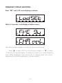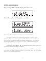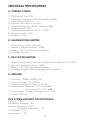
1
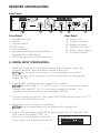
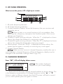
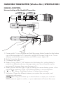
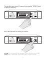
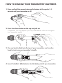
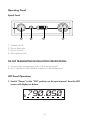
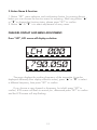
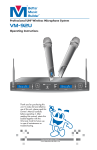
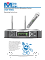
TM
®
Professional UHF Wireless Microphone System
VM-99U
-9
VM
EM
ST
ic
PH
RO
IC
UH
TR
U
LC E D
DIGD D IVER
IT ISPL SIT
AL A Y
PL Y
L
F
W
IREL
ES
TM
SM
Be
tte
ON
rM
us
E SY
Bu
ild
er
®
9U
CH
002
Operating Instructions
TM
Better Music Builder ®
POWER
B.CH B
ONES
PH
RF
5 10 15 20 25 30 35
40
AF -30 -25 -20 -15 -10 -5 0 PEAK
MIN
MAX
UHF
VM-99U
0.01 750.000
M
H
Z
UP
TRUE DIVERSITY
LCD DISPLAY
DIGITAL PLL
DOWN
SET
II
PROFESSIONAL WIRELESS MICROPHONE RECEIVER
Thank you for purchasing this
unit. To make full and effective
use of this unit, please read this
Owner's Manual carefully
before operating it. After
reading this manual, retain this
booklet together with the
Warranty Card for future use
in case of maintenance or
troubleshooting.
Passionate about Music
www.BetterMusicBuilder.com
CONTENTS
FOREWORD......................................................................................... 2
RECEIVER SPECIFICATION.................................................................. 2~5
HANDHELD TRANSMITTER SPECIFICATION............................................. 6
HOW TO SET UP YOUR HANDHELD TRANSMITTER............................. 7~9
HOW TO MONITOR YOUR VOCAL................................................ 10~11
HOW TO CHANGE YOUR TRANSMITTER’S BATTERIES.......................... 12
TIE-CLIP TRANSMITTER SPECIFICATION........................................... 13~17
SYSTEM TECHNICAL SPECIFICATION.................................................... 18
CAUTION............................................................................................ 19
VM-99U FCC FREQUENCY 750 MHz and 800 MHz............................... 20
FREQUENCY SCAN GROUPS FOR BAND C & BAND D......................... 21
US UHF WIRELESS OPERATING FREQUENCIES................................ 22~23
FOREWORD
Thank you for purchasing our company’s product VM-99U. This
product is designed using America’s most advanced audio technology
up to date.
The system has the characteristic as follows:
1. Working frequency range: UHF520-810MHz (tunable)
2. CPU control: PLL frequency compose technique)
3. CPU controlled true diversity system for advance break up and
receiver control of left and right channels
4. LCD (Liquid Crystal Display) screen
5. Transmitter and receiver audio system for high-pass, low-pass &
band-pass filter technique to avoid noise and keep sound quality
RECEIVER SPECIFICATION
A. NAMES & FUNCTION:
Front Panel:
TM
Better Music Builder ®
POWER
0.01 750.000
B.CH B
RF
ONES
PH
5 10 15 20 25 30 35
40
AF -30 -25 -20 -15 -10 -5 0 PEAK
MIN
1
2
MAX
3
UHF
VM-99U
M
H
Z
UP
TRUE DIVERSITY
LCD DISPLAY
DIGITAL PLL
DOWN
SET
II
PROFESSIONAL WIRELESS MICROPHONE RECEIVER
4
2
5
6
7
RECEIVER SPECIFICATION
Rear Panel:
DC-POWER
DC13~15V
600mA
OUTPUT
TM
Better Music Builder ®
MODEL NO. VM-99U
VOLUME
8
36120060908-22
MHz
MHz
MIX
MIN
0
Serial:
Frequency: A
Frequency: B
TRUE DIVERSITY
CALIFORNIA, UNITED STATES OF AMERICA
Comments? E-mail: [email protected]
www.BetterMusicBuilder.com
ENGINEERED AND DESIGN IN U.S.A.
MAX
3
ANTENNA-A
BALANCED
9
10
Front Panel:
1. Headphones jack
2. Power
3. Volume control
4. LCD screen
5. locking display
6. (up and down button) selects different
frequency & model settings
7. Model programming setup (set button)
UNBALANCED
11
0678!
ANTENNA-B
12
13
Rear Panel:
8. Power jack
9. Antenna socket A
10. Balanced output
11. Unbalanced output
12. Audio output volume
13. Antenna socket B
B. MODEL SETUP SPECIFICATION:
1. Install two antennas to the antenna socket A B of the rear panel, the
direction between them should be adjusted about 90°.
NOTE Do not install in too firmly or it may damage your system’s
antenna output. (Your warranty may be terminated if you damage the
system like this.)
2. Insert the DC power to the rear panel of your system.
NOTE Only use a DC 13~15v DC power, if you use any other power
voltage other than DC 13~15v you may damage the system. Your
warranty may be terminated if you damage it like this.
3. Turn the volume to minimum, then press and hold the power button for 2-3
seconds until LCD screen is on.
4. Adjust the receiver’s status to your liking.
NOTE Receiver adjustments will be mentioned on pages 4-6.
5. To turn off power press and hold the power button for 2-3 seconds. The
LCD screen will display “OFF” as
M
H
off
Z
shown to on the diagram to the right.
RF 5 10 15 20 25 30 35 40
Then, power will automatically shut off.
AF -30 -25 -20 -15 -10 -5 0 PEAK
3
C. LCD PANEL OPERATION:
After turn on the power, LCD is light up as screen:
7
0.01
00000
1
RF
2
AF -30 -25 -20 -15 -10 -5 0 PEAK
5 10 15 20 25 30 35
3
40
M
H
Z
4
I II
MUTE
5
6
1. RF (radio frequency) Indicator
2. AF (audio frequency) Indicator
3. Current Frequency Display: shows the frequency that your receiver and
transmitter are on.
NOTE If there is static or no sound coming out of your speakers, than
there may be a frequency interruption from another system. If this occurs
change your frequency.
4. Channel A signal receiving indicator: When the “I” is displayed as shown
above, this means that Antenna A is receiving a signal.
5. Channel B signal receiving indicator: When the “II” is displayed as shown
above, this means that Antenna B is receiving a signal.
6. Mute Indicator: When the “MUTE” is displayed as shown above, this
means that the system is currently not receiving any vocal signal.
7. Current Channel Display
NOTE Make sure your receiver’s channel/frequency matches the one in
your transmitter’s channel/frequency. (Channel/frequency display may be
changed in the transmitter’s settings. Refer to pg 7-9.)
D. CHANGING FREQUENCY
Press “SET”, LCD will display below screen:
0.01 750.000
B.CH B
RF
5 10 15 20 25 30 35
40
AF -30 -25 -20 -15 -10 -5 0 PEAK
The number displayed
depends on your current setting.
NOTE
M
H
Z
II
Press set for LCD screen displays several numbers as shown above. This
is the frequency current station, to change frequency use the “▲” or “▼”
button to select a different channel, then the LCD screen will flash to remind
you to confirm please press set again to confirm.
4
E. THE RECEIVER SENSITIVITY ADJUSTING MENU:
Keep pressing the set button until LCD screen displays “SQELCH” as shown
below:
RF
5 10 15 20 25 30 35
15
M
H
Z
RF
40
AF -30 -25 -20 -15 -10 -5 0 PEAK
p
5qELCH
5 10 15 20 25 30 35
M
H
Z
40
AF -30 -25 -20 -15 -10 -5 0 PEAK
After 2-3 seconds, the screen will display “XX* dB” (*various numbers,
depending on your current adjustments). This is the status of your receiver’s
current sensitivity level. You can press the “▲” or “▼” buttons to select a
different level. After you made your selection, the LCD screen will flash to
remind you to confirm, please press set to confirm.
NOTE If you want a more active signal between the transmitter and receiver
set the sensitivity level to at least 15dB. Setting the sensitivity level higher lets
the signal become active from a further distance.
F. SYSTEM LOCKING MENU:
Locking or Unlocking your system’s current statuses:
loc
RF
on
5 10 15 20 25 30 35
locoff
M
H
Z
RF
40
5 10 15 20 25 30 35
M
H
Z
40
AF -30 -25 -20 -15 -10 -5 0 PEAK
AF -30 -25 -20 -15 -10 -5 0 PEAK
Keep pressing the set button until the LCD screen displays “LOCK”. After
2-3 seconds screen will display “LOC ON” or “LOC OFF” as shown above
(“LOC ON” means that system is locked [if system is locked the lock indicator
will display on the LCD screen, in this mode no adjustment can be made to
the system and system can not be powered off. “LOC OFF” means system is
unlocked, in this mode adjustments can be made to the system and power
can be powered off.) Press the “▲” button to switch to “LOC ON” to lock
system’s current status or press the “▼” button to switch to “LOC OFF” to
enable system adjustments.
NOTE
If system is locked the lock indicator will be on.
5
HANDHELD TRANSMITTER (Wireless Mic.) SPECIFICATION
NAMES & FUNCTION:
Uncover Looking of the Handheld Transmitter:
ALKALINE
BATTERY
ALKALINE
BATTERY
AA
LR6.AA
1
2
LR6.AA
Battery Slot
UHF
TRUE DIVERSITY
LCD DISPLAY
DIGITAL PLL
AA
VM-99U
WIRELESS SYSTEM ENGINEERING IN USA
3
CH 002
4
5
CH 002
6
7
1. Power switch: To turn on press and hold the power button located on the bottom
cap of the transmitter for 2-3 seconds, until the LCD screen’s light is on. To turn
off press and hold the power button until LCD screen’s light is off.
2. Built-in Transmitter Antenna
3. Condenser and grille
4. Battery Cover: Insert 2 “AA” batteries into the battery slot, putting battery’s
polarity on different ends may damage system and your warranty may be
terminated if damage does occur because of it.
5. Battery power indicator light: If light is flashing this means battery power is low
and must be replaced, if light is not flashing battery is at normal power.
6. “▲” or “▼” buttons: Adjustment buttons to adjust system statuses.
7. Set button: Opens the different statuses your system lets you adjust, and
adjustment confirmation.
NOTE After using set and the up or down buttons to adjust your receiver’s
status, press set again to confirm, or your adjustments will remain the same.
6
HOW TO SET UP YOUR HANDHELD TRANSMITTER
(Wireless Mic.)
Firstly, push the release button on the bottom cap.
Green
Blue
Yellow
Silver
Orange
Black
(*Optional: You can switch the caps with 6 different colors; green, blue,
yellow, silver, orange and black. Sold separately)
If you or anyone do any damage, either accidental or incidental, on
the transmitter [microphone] head’s grille, we have the right to void your
warranty.
NOTE
Second, twist open the handle.
CH 002
when twisting back on the handle don’t twist it in too firmly or it may
damage the transmitter [wireless microphone].
NOTE
NOTE
Damage because of improper usage will void your warranty.
7
Third, Pull open handle to reveal the transmitter’s LCD monitor.
VM-99U
WIRELESS SYSTEM ENGINEERING IN USA
CH 002
CH 002
NOTE When pulling out handle make sure that you pull it straight out then
when you hit a click wedge the handle a little bit and it will loosen, then pull it
straight out.
Fourth, to change the settings press set to switch to the mode you want to
adjust on the transmitter, and up and down to select press set again to
confirm. When the battery is low the light above the LCD screen will be
flashing.
To modify the other modes, press “SET” to that mode and the “▲”and “
▼” button to select the adjustments. Press “SET” again to confirm.
CH 002
Match your frequency on the transmitter to those on the receiver for a
better signal.
NOTE
NOTE
If you do not press set to confirm no adjustments will be made.
NOTE
Damage because of improper usage will void your warranty.
8
Setting Up your Handheld Transmitter (Wireless Mic.)
CH 002
To change frequency/channel press set until LCD screen displays CH
001* (channel display values) or 750.000* (frequency display values)
(*varies depends on current settings). Press the up or down buttons to select a
different channel/frequency (channel ranges from 1-9 & A-F). Then the LCD
screen will flash. Press set again to confirm (if you don’t confirm no adjustments
will be made.)
NOTE Match your frequency/channel to the receiver’s the RF indicator on the
receiver will show a signal.
To change display between frequency/channel:
Frequency displays frequency signal’s actual units, while channel displays
a substitute letter or number. (Refer to pg.20 for the frequency’s value in
channel and actual unit)
Keep pressing set until LCD screen displays “disply”. After 1-2 seconds
screen will show FYE 9u (for frequency) or CHAnnl (for channel). Note: Current
display depends on settings. Press the up or down button to switch between
the two. Then the LCD screen will flash. Press set again to confirm (if you don’t
confirm no adjustments will be made.)
To unlock/lock your settings:
In lock mode settings can not be adjusted and transmitter can not be
powered off, in unlock mode all settings can be adjusted.
NOTE
Keep pressing set until LCD screen displays “loc Set” after 1-2 seconds
screen will display Loc OFF (unlock) or Loc on (locked). Press up or down to
switch between the two settings. Then the LCD screen will flash. Press set
again to confirm (if you don’t confirm no adjustments will be made.)
9
HOW TO MONITOR YOUR VOCAL
(*Optional: You can insert a Stereo Headphone in the headphone jack on the
front panel of your receiver to monitor your vocal via Headphone.)
TM
Better Music Builder ®
POWER
0.01 750.000
B.CH B
RF
ONES
PH
5 10 15 20 25 30 35
M
H
Z
40
MAX
UP
TRUE DIVERSITY
LCD DISPLAY
DIGITAL PLL
DOWN
SET
II
AF -30 -25 -20 -15 -10 -5 0 PEAK
MIN
UHF
VM-99U
PROFESSIONAL WIRELESS MICROPHONE RECEIVER
If you or anyone do any damage on the
receiver’s headphone jack, either accidentally or
intentionally we have the right to void your warranty.
NOTE
You can adjust your receiver’s frequency by pressing the “UP” button to
select your frequency.
TM
Better Music Builder ®
POWER
B.CH B
RF
ONES
PH
5 10 15 20 25 30 35
40
AF -30 -25 -20 -15 -10 -5 0 PEAK
MIN
MAX
UHF
VM-99U
0.01 750.000
M
H
Z
UP
TRUE DIVERSITY
LCD DISPLAY
DIGITAL PLL
DOWN
SET
II
PROFESSIONAL WIRELESS MICROPHONE RECEIVER
NOTE If you or anyone do any man made damage on the receiver’s buttons,
either accidentally or intentionally, we have the right to void your warranty.
10
You can adjust your receiver’s frequency by pressing the “DOWN” button
to select your frequency.
TM
Better Music Builder ®
POWER
B.CH B
RF
ONES
PH
5 10 15 20 25 30 35
M
H
Z
40
MAX
UP
TRUE DIVERSITY
LCD DISPLAY
DIGITAL PLL
DOWN
SET
UP
TRUE DIVERSITY
LCD DISPLAY
DIGITAL PLL
DOWN
SET
II
AF -30 -25 -20 -15 -10 -5 0 PEAK
MIN
UHF
VM-99U
0.01 750.000
PROFESSIONAL WIRELESS MICROPHONE RECEIVER
Press “SET” afterwards to confirm your selection.
TM
Better Music Builder ®
POWER
0.01 750.000
B.CH B
RF
ONES
PH
5 10 15 20 25 30 35
40
AF -30 -25 -20 -15 -10 -5 0 PEAK
MIN
MAX
UHF
VM-99U
M
H
Z
II
PROFESSIONAL WIRELESS MICROPHONE RECEIVER
NOTE If you or anyone do any damage on any part of the receiver either
accidentally or intentionally, we have the right to void your warranty.
11
HOW TO CHANGE YOUR TRANSMITTER’S BATTERIES
1. Press and hold the power button on the bottom of the cap for 3-5
seconds until your transmitter is off.
2. Press the release button on the cap and pull out
(*Optional: You can replace your cap with different colors to recognize
your transmitter easily)
3. Use one hand to hold onto the top of your transmitter, use the other
hand to twist out your transmitter’s handle.
LR6.AA
LR6.AA
AA
ALKALINE
BATTERY
4. Insert 2 double A (AA) batteries into the battery slot of your transmitter.
LR6.AA
LR6.AA
AA
12
ALKALINE
BATTERY
TIE-CLIP TRANSMITTER SPECIFICATION
NAMES & FUNCTION:
Transmitter:
1
Outside Picture
1. Antenna
2. Microphone Jack
3. LCD
4. Battery Cover
5. Tie-Clip
6. Microphone Extension Jack
2
UHF-SERIES
3
4
5
6
1
Inside Picture
1. Power Switch
2. Channel Selection
3. Setting
4. Battery Slot
5. Volume Control
6. Transmitter Power Switch on/off
Side-face Picture :
UHF-SERIES
5
HI
POWER
LO
GAIN
SET
2
3
6
4
Headset Microphone (Accessories):
Tie Clip
13
Operating Panel:
Apical Panel
1
1.
2.
3.
4.
2
3
4
Antenna Jack
Power Indicator
Power Switch
Microphone Jack
TIE-CLIP TRANSMITTER INSTALLATION SPECIFICATION:
1. Connect the microphone jack on the apical panel
2. Put 2 double A (AA) alkaline batteries in the battery box.
LCD Panel Operation:
BAT
1. Switch “Power” to the “ON” position on the apical panel, then the LCD
screen will display as below:
790.050
14
2. Button Name & Function:
1. Button “SET”, menu selection and confirmation button, by pressing the set
button you can choose the function menu for adjusting. After using button “▲”
or “▼” to change the function status, please press “SET” to confirm.
2. Button “▲” or “▼” is to select adjustments of every menu.
CHANNEL DISPLAY AND MENU ADJUSTMENT:
BAT
BAT
Press “SET”, LCD screen will display as below:
ch 000
790.050
The menu displays the working frequency of the transmitter (it can be
displayed differently from display selection menu), press “▲” or “▼” to select
a different frequency, then press “SET” to confirm.
If you choose a new channel or frequency, but didn’t press “SET” to
confirm, LCD screen will flash to remind you, afterwards press “SET” to confirm
and the LCD screen will stop flashing.
15
FREQUENCY DISPLAY SELECTION:
BAT
Press “SET” until, LCD screen displays as below:
BAT
BAT
After 2~3 seconds, it will display as below screen:
(The above screen displays according to the present setting)
Press “▲” to select “FYE 9u” for frequency display, or “▼” to select
“CHA nnl” for channel display. In frequency mode, your current frequency
level will be displayed in their actual units, In channel mode your current
frequency level will be displayed in “whole numbers”.
16
SYSTEM LOCKING MENU:
BAT
Keep pressing “SET” until, LCD display the below screen:
BAT
BAT
After 2~3 seconds, it will display the screen below:
(The screen above displays according to your present status)
This menu’s function is for locking the transmitter’s working status
(Channel, Displaying, Selecting, Power ON/OFF etc.). If it is in “Loc on”
(lock position), it can not change the present working status, also can not
power off the receiver. If it is in the “LOC OFF” (unlock position), it can
change all of the current settings.
When pressing the “▲” or “▼” to change the menu’s status, press “SET”
to confirm, otherwise it will be ineffective.
If you change the previous status, but didn’t press “SET” to confirm, the
LCD screen will flash to remind you after 2~3 seconds. Press “SET” to confirm,
then LCD screen will stop flashing.
17
TECHNICAL SPECIFICATION
A. OVERALL SYSTEM
1.
2.
3.
4.
5.
6.
7.
8.
9.
OSD Model: PLL LOCK
Operating Frequency: 520~820 MHz (Tunable)
Modulation Model: FM
Maximum Deviation: ± 45 KHz
Frequency Response: 80Hz~15KHz(± 3dB)
Image Rejection: ≤ 1%
Operating Temperature: -10 °C~+55°C
Shipping weight: 5 lbs
Quantity: 1 Set
B. HANDHELD TRANSMITTER
1.
2.
3.
4.
Output Power: 25 • ~30 mew
Harmonic Interference Ratio: -50dB
Battery: 2 PCS AA Type Alkaline Battery
Cartridge: Dynamic
C. TIE-CLIP TRANSMITTER
1.
2.
3.
4.
Output Power(Lowest): 4~6 mW Output Power(Highest): 20~30mW
Harmonic Interference Ratio: -50dB
Battery: 2 PCS AA Type Alkaline Battery
Cartridge: Single polar Pattern capacity Microphone
D. RECEIVER
1.
2.
3.
4.
Sensitivity: 12dBuV (80dB S/N)
Sensitivity Range: 12~32dBuV
Harmonic Interference Ratio: ≥ 75 dB
Audio Output: Balanced: 0~0.5V/600Ω
Audio output: 0~0.5V/5KΩ
5. Power Supply: Connect direct power 12~14V
6. Current: 300 mA
THIS SYSTEM INCLUDES THE FOLLOWING:
Receiver: 1 Set
Handheld Transmitter: 1Set
Antenna: Receiver × 2 PCS
Handheld Transmitter × 1 PC
AC Adapter: 1 Set
User Manual: 1 PC
18
WARRANTY
One-Year Limited Warranty for Home Use Equipment
Our one-year warranty applies to speakers, amplifiers, mixers and microphones for
home use only. It covers both parts and labors. The warranty becomes effective from
the date of your purchase for one year.
Our warranty only covers defects due to product defectiveness with free of defects in
materials or workmanship. However, our warranty does not cover defects due to
normal wears, damage in transit, improper use, abuse or failure to follow the proper
instructions for maintenance. This warranty is void in the event of unauthorized repairs,
alternations, modifications and removing of the product label.
Please also note that our warranty does not cover any shipping cost for the return of
defective products to us for inspection, repair and maintenance. Our warranty for
Better Music Builder products can only be executed in North America.
NOTE
Our warranty does not cover the battery for wireless microphone products.
90-Day Limited Warranty for Public and Commercial Use Equipment
Our 90-day warranty applies to speakers, amplifiers, mixers and microphones for
both public and commercial use such as restaurant, coffee shop, KTV nightclub,
church and school, etc. It covers both parts and labors. The warranty becomes
effective from the date of your purchase for 90 days.
To Register Your Warranty
Please fill out the warranty card that came with your unit, download or submit online
warranty form. However, we need the invoice for your purchase in order to process
this warranty. You may also register your warranty online.
Please visit our website at www.bettermusicbuilder.com.
PRECAUTION
1. If you want to use more than one of this system, please select the work frequency
(or signal channel) carefully so as to avoid disturbing.
2. The input power voltage of the receiver is 120V (±10%). If it is too low or too
high, it will affect the work of the machine.
3. When you install the battery, you must not reverse the electrode or you will
damage the machine.
4. When using the sensitivity solution function, the numerical value you select must be
at least 15dB. Otherwise, if the distance is too far, its signal-to noise radio goes
worse.
This symbol, wherever it appears, alerts
you to the presence of uninsulated
dangerous voltage inside the enclosure
voltage that may be sufficient to constitute
a risk of shock.
RISK OF ELECTRIC SHOCK
DO NOT OPEN
Caution: To reduce the risk of electrical shock, do not
remove the cover (or back). No user serviceable parts
inside: refer servicing to qualified personnel.
Warning: To reduce the risk of fire or electrical shock,
do not expose this appliance to rain or moisture.
19
This symbol, wherever it appears, alerts
you to important operating and
maintenance instructions in the
accompanying literature. Read the
manual.
VM-99U FCC FREQUENCY 750 MHz and 800 MHz
VM-99U FCC Frequency 750 MHz
TV Ch.
Receiver Frequency
Transmiter Frequency
1
750.025
000
2
752.800
001
3
753.625
002
4
754.525
003
5
755.456
004
6
756.150
005
7
758.130
006
8
758.850
007
9
760.050
008
10
760.650
009
11
760.650
00A
12
761.650
00B
13
762.150
00C
14
763.850
00D
15
764.350
00E
16
764.875
00F
TV Ch.
Receiver Frequency
Transmiter Frequency
1
785.025
000
2
785.825
001
3
787.000
002
4
788.250
003
5
789.000
004
6
790.750
005
7
791.250
006
8
792.750
007
008
VM-99U FCC Frequency 800 MHz
9
795.000
10
795.750
009
11
797.500
00A
12
798.000
00B
13
800.325
00C
14
802.275
00D
15
803.500
00E
16
804.625
00F
20
FREQUENCY SCAN GROUPS FOR BAND C & BAND D
Band C
Band C Scan Group 1
Band C Scan Group 2
Band C Scan Group 3
TV Ch. Frequency – MHz *
25
(None)
0
26
542.750
26
545.500
26
547.125
26
547.375
4
27
549.750
27
550.375
27
550.625
3
28
557.250
28
557.500
28
559.250
28
559.500
4
29
562.000
29
563.375
29
563.625
3
30
566.000
30
566.250
2
TV Ch. Frequency – MHz *
25
541.500
1
26
542.750
26
544.375
26
544.750
26
545.750
26
547.500
5
27
(None)
0
28
554.250
28
556.125
28
557.500
28
559.375
4
29
560.000
29
561.875
29
562.250
29
563.250
29
565.500
5
30
566.000
1
TV Ch. Frequency – MHz *
25
541.500
1
26
542.125
26
543.500
26
544.000
26
546.250
4
27
548.250
27
549.750
2
28
555.750
28
556.625
28
558.250
28
559.375 4
29
560.125
29
561.500
29
564.000
29
564.250
4
30
566.125
1
Band D Scan Group 1
Band D Scan Group 2
Band D Scan Group 3
TV Ch. Frequency – MHz *
44
655.500
1
45
658.000
45
658.375
45
659.250
45
659.500
45
661.500
5
46
662.375
46
662.750
2
47
669.625
47
671.750
2
48
674.750
48
675.750
48
676.125
48
678.000
48
678.250
48
679.500
6
49
(None)
0
TV Ch. Frequency – MHz *
44
655.875
1
45
656.250
45
658.500
45
659.750
45
660.000
45
660.500
5
46
664.375
46
665.500
2
47
671.625
47
672.000
2
48
674.000
48
674.500
48
675.750
48
676.750
48
678.250
5
49
680.250
1
49
(None)
0
TV Ch. Frequency – MHz *
44
655.500
44
655.750
2
45
656.625
45
658.500
45
658.750
45
659.500
4
46
662.750
46
665.250
2
47
671.250
47
672.375
47
673.125
3
48
674.125
48
674.500
48
675.375
48
678.625
48
679.125
5
Band D
* Number of wireless frequencies in TV Channel.
21
US UHF WIRELESS OPERATING FREQUENCIES
Band C: 541.500 - 566.375 MHz
TV Ch.
25
---
---
---
---
541.500 541.625 541.750 541.875
26
542.000 542.125 542.250 542.375 542.500 542.625 542.750 542.875
26
543.000 543.125 543.250 543.375 543.500 543.625 543.750 543.875
26
544.000 544.125 544.250 544.375 544.500 544.625 544.750 544.875
26
545.000 545.125 545.250 545.375 545.500 545.625 545.750 545.875
26
546.000 546.125 546.250 546.375 546.500 546.625 546.750 546.875
26
547.000 547.125 547.250 547.375 547.500 547.625 547.750 547.875
27
548.000 548.125 548.250 548.375 548.500 548.625 548.750 548.875
27
549.000 549.125 549.250 549.375 549.500 549.625 549.750 549.875
27
550.000 550.125 550.250 550.375 550.500 550.625 550.750 550.875
27
551.000 551.125 551.250 551.375 551.500 551.625 551.750 551.875
27
552.000 552.125 552.250 552.375 552.500 552.625 552.750 552.875
27
553.000 553.125 553.250 553.375 553.500 553.625 553.750 553.875
28
554.000 554.125 554.250 554.375 554.500 554.625 554.750 554.875
28
555.000 555.125 555.250 555.375 555.500 555.625 555.750 555.875
28
556.000 556.125 556.250 556.375 556.500 556.625 556.750 556.875
28
557.000 557.125 557.250 557.375 557.500 557.625 557.750 557.875
28
558.000 558.125 558.250 558.375 558.500 558.625 558.750 558.875
28
559.000 559.125 559.250 559.375 559.500 559.625 559.750 559.875
29
560.000 560.125 560.250 560.375 560.500 560.625 560.750 560.875
29
561.000 561.125 561.250 561.375 561.500 561.625 561.750 561.875
29
562.000 562.125 562.250 562.375 562.500 562.62 5562.750 562.875
29
563.000 563.125 563.250 563.375 563.500 563.625 563.750 563.875
29
564.000 564.125 564.250 564.375 564.500 564.625 564.750 564.875
29
565.000 565.125 565.250 565.375 565.500 565.625 565.750 565.875
30
566.000 566.125 566.250 566.375
---
---
---
Avoid using same frequencies as TV channels or other radio signals for better performance.
22
---
Band D: 655.500 - 680.375 MHz
TV Ch.
44
---
---
---
---
655.500 655.625 655.750 655.875
45
656.000 656.125 656.250 656.375 656.500 656.625 656.750 656.875
45
657.000 657.125 657.250 657.375 657.500 657.625 657.750 657.875
45
658.000 658.125 658.250 658.375 658.500 658.625 658.750 658.875
45
659.000 659.125 659.250 659.375 659.500 659.625 659.750 659.875
45
660.000 660.125 660.250 660.375 660.500 660.625 660.750 660.875
45
661.000 661.125 661.250 661.375 661.500 661.625 661.750 661.875
46
662.000 662.125 662.250 662.375 662.500 662.625 662.750 662.875
46
663.000 663.125 663.250 663.375 663.500 663.625 663.750 663.875
46
664.000 664.125 664.250 664.375 664.500 664.625 664.750 664.875
46
665.000 665.125 665.250 665.375 665.500 665.625 665.750 665.875
46
666.000 666.125 666.250 666.375 666.500 666.625 666.750 666.875
46
667.000 667.125 667.250 667.375 667.500 667.625 667.750 667.875
47
668.000 668.125 668.250 668.375 668.500 668.625 668.750 668.875
47
669.000 669.125 669.250 669.375 669.500 669.625 669.750 669.875
47
670.000 670.125 670.250 670.375 670.500 670.625 670.750 670.875
47
671.000 671.125 671.250 671.375 671.500 671.625 671.750 671.875
47
672.000 672.125 672.250 672.375 672.500 672.625 672.750 672.875
47
673.000 673.125 673.250 673.375 673.500 673.625 673.750 673.875
48
674.000 674.125 674.250 674.375 674.500 674.625 674.750 674.875
48
675.000 675.125 675.250 675.375 675.500 675.625 675.750 675.875
48
676.000 676.125 676.250 676.375 676.500 676.625 676.750 676.875
48
677.000 677.125 677.250 677.375 677.500 677.625 677.750 677.875
48
678.000 678.125 678.250 678.375 678.500 678.625 678.750 678.875
48
679.000 679.125 679.250 679.375 679.500 679.625 679.750 679.875
49
680.000 680.125 680.250 680.375
---
---
---
Avoid using same frequencies as TV channels or other radio signals for better performance.
23
---
TM
®
Passionate about Music
www.BetterMusicBuilder.com
Printed on 100% Recycled Paper ©2007 Better Music Builder (USA) Comments E-mail to [email protected] All Rights Reserved in USA.