1
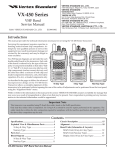
VX-456 UHF CBRS Transceiver Operating Manual Contents Introduction.................................................................................... 1 Important Information Concerning UHF CB Radio.................. 2 Features........................................................................................... 4 Warning! RF Exposure Requirements......................................... 6 Controls & Connectors.................................................................. 8 LCD Icons & Indicators................................................................ 9 Before You Begin.......................................................................... 10 Battery Pack Installation and Removal.................................. 10 Low Battery Indication.......................................................... 10 Battery Charging.................................................................... 10 Belt Clip Installation and Removal........................................ 12 MIC/SP CAP Installation....................................................... 13 Operation...................................................................................... 14 Preliminary Steps................................................................... 14 Operation Quick Start............................................................ 14 ARTSTM . ...................................................................................... 17 Advanced Operation.................................................................... 18 Field Programming Mode........................................................... 24 User Set Mode.............................................................................. 25 Optional Accessories.................................................................... 30 Specifications................................................................................ 32 Vertex Standard Products Limited Warranty & Liability....... 36 Congratulations! You now have at your fingertips a valuable communications tool-a Vertex Standard two-way radio! Rugged, reliable and easy to use, your Vertex Standard radio will keep you in constant touch with your colleagues for years to come, with negligible maintenance down-time. Please take a few minutes to read this manual carefully. The information presented here will allow you to derive maximum performance from your radio, in case questions arise later on. We’re glad you joined the Vertex Standard team. Call on us anytime, because communications is our business. Let us help you get your message across. Notice!: There are no owner-serviceable parts inside the radio. All service jobs must be referred to an authorized Vertex Standard Service Representative. Consult your Authorized Vertex Standard Dealer for installation of optional accessories. Introduction The VX-456 is meet the varied commercial radio needs of Australian industry. The compact case combines diecast chassis with the clean, tough poly-carbonate resin front panel. Its shockproof versatility will allow you to operate the radio in the toughest environment. The VX-456 allows to 80-channel capacity which can be programmed with an 8-character Alpha-Numeric Tag. Important channel frequency data is stored in EEPROM and flash memory on the CPU, allows the user to change the receiving frequency while the VX-456 is in the Field programming mode. The pages which follow will detail the many advanced features provided in the VX-456 transceiver. After reading this manual, you may wish to consult with your Network Administrator regarding precise details of the configuration of this equipment for use in your application. VX-456 Operating Manual 1 Important Information Concerning UHF CB Radio The use of the Citizen Band Radio Service is licensed in Australia by the ACMA radio communications (Citizens Band Radio Stations) class licence and in new Zealand by the ministry of Economic Development New Zealand (MED). A General user radio licence for Citizens Band Radio and operation is subject to conditions contained in those licences. The class licence for users and equipment operating in the CB/PRS 477 MHz band has been amended. This radio meets the new 80 channel standard. In simple terms the same amount of spectrum is available; however, radio transceivers can now operate in a narrower bandwidth and hence use less spectrum. These radios are generally referred to as narrowband or 12.5 kHz radios. By using 12.5 kHz channel spacing instead of 25 kHz, the 40 channels originally allocated can now be expanded to 80 channels thereby doubling the channel capacity and relieving congestion in the UHF CB/PRS band. 2 Original 40 channel wideband radios will continue to operate on the original 40 channels, however they will not be able to converse on the newer channels 41 - 80. The newer narrowband radios will be able to converse with all older 40 channel wideband radios on all channels 1 to 40 as well as the newer channels allocated from 41 to 80. The mixing of narrowband and wideband radios in the same spectrum can cause some possible operating issues of interference and varying levels of received volume. Possible Issues When a new narrowband radio receives a transmission from an older wideband radio the speech may sound loud and distorted - simply adjust your radio volume for best performance. When an older wideband radio receives a signal from a new narrowband radio, the speech may sound quiet - simply adjust your radio volume for best performance. VX-456 Operating Manual Important Information Concerning UHF CB Radio Depending on how close your receiving radio is to another transmitting radio, there can be interference from the transmitting radio if it is using a channel adjacent to the channel you are listening to. Simply try going up or down a few channels from the currently selected channel. The above situations are not a fault of the radio but a symptom of operating wideband and narrowband radios in the same bandwidth. This possible interference will decrease over time as the population of wideband radios ages and decreases. Further information and updates are available from the Australian communications and media Authority (ACMA) at www.acma.gov.au and the Ministry of Economic Development (MED), radio spectrum management at: www.rsm.govt.nz VX-456 Operating Manual Emergency Channels The ACMA has allocated channels 5/35 for emergency use only. Channel 5 is the primary simplex Emergency channel. Where a channel 5 repeater is available, you should select Duplex on CH 5. Note: Channel 35 is the input channel for the channel 5 repeater therefore channel 35 should also not be used for anything other than emergency transmissions. Telemetry Channels ACMA regulations have allocated channels 22 and 23 for telemetry only applications and have prohibited the transmission of speech on these channels. Consequently your radio has a transmit inhibit applied to channels 22 and 23. In the event additional telemetry/telecommand channels are approved by the ACMA, these channels shall be added to those currently listed where voice transmission is inhibited. Currently transmissions on channels 61, 62 and 63 are also inhibited and these channels are reserved for future allocation. 3 Features Microprocessor Controlled Frequency Synthesiser: Allows user programmable control of scanning, channel memories and selected feature options. Voice Encryption: The Voice Encryption feature protect the privacy of your communication from other groups. Programmable Scan Function: Scans the selected UHF CB channels with both Group and Open Scan functions available. Priority Channel: User programmable Priority Channel feature allows your working channel to be instantly recalled at the press of a programmable key. High Contrast Liquid Crystal Display: Large LCD (Liquid Crystal Display) provides a visual indication of the selected channel and all selected functions at a glance. Field Programming Mode: Allows the user to change the receiving frequency and Wide/Narrow receiver filter of the memory channel by the simple operation from the keypad. User Menu Mode: Allows the user to define or configure various settings of the radio by the simple operation from the keypad. 4 In-Built CTCSS & DCS: User selectable Continuous Tone Coded Squelch System and Digital Coded Squelch system option provides silent channel operation on individual channels. TOT (Time Out Timer): This radio has a built-in time-out timer that automatically limits transmissions to a maximum of 3 minutes of continuous operation. This feature is required by the ACMA to prevent accidental blocking of the frequency should your PTT switch become jammed or be otherwise pressed accidentally. The time-out period can be changed to a shorter time by your dealer. IP57 Water Resistance: This radio is designed to meet the IP57 Water Resistance specification. The IP57 protected against the effects of immersion in water up to 1 m depth for 30 minutes. Note: Water resistance of the transceiver (IP57: 1 meter / 30 minutes) is assured only when the following conditions: r Battery pack is attached to the transceiver; r Antenna is connected to the antenna jack; r and MIC/SP cap is installed in the MIC/SP jack. VX-456 Operating Manual Features Repeater and Duplex Mode: Duplex operation allows the radio to transmit on a different frequency to that which it receives. This allows operation through repeater stations. A repeater station consists of a linked transmitter/receiver combination installed in a prominent location. The repeater is designed to receive signals on a designated channel and retransmit them on another channel. Repeater stations, usually located on mountaintops or other high locations, provide a dramatic extension of the communication range for low-powered handheld or mobile transceivers. Simplex Repeater Operation z 7. 47 H M 50 17 z H M RX : TX 6.4 7 :4 0 25 Hz 0M 25 T .4 MH The Repeater channel is set in channels 1 - 8 and 41 - 48 which have been allocated for repeater use. In the Repeater channel, the “D” notation is appeared on the right side of the channel indication. Refer to page 34 for details of the Channel List. 6 47 X: z 50 .17 77 4 X: This radio can easily perform the Repeater operation by selecting the CH selector knob to the repeater channel. R Repeater Station TX: 476.4250 MHz RX: 477.1750 MHz Normally, UHF radios transmit and receive on the same frequency - known as simplex operation. However to communicate through repeaters, your radio must be able to transmit and receive on different channels - otherwise known as Duplex operation. Channel [CB-01D] VX-456 Operating Manual Channel [CB-01D] 5 Warning! RF Exposure Requirements This radio generates RF electromagnetic energy during transmit mode. To ensure that your expose to RF electromagnetic energy, always adhere to the following guidelines: This radio is NOT approved for use by the general population in an uncontrolled exposure environment. This radio is restricted to occupational use, work related operations only where the radio operator must have the knowledge to control his or her RF exposure conditions. When transmitting, hold the radio in a vertical position with its microphone 2 inches (5 cm) away from your mouth and keep the antenna at least 2 inches (5 cm) away from your head and body. The radio must be used with a maximum operating duty cycle not exceeding 50%, in typical Push-toTalk configurations. DO NOT transmit for more than 50% of total radio use time (50% duty cycle). To keep the Body Worn configuration with the Vertex Standard CLIP-20 belt-clip, reduce the maximum operating duty cycle still more. The radio is transmitting when the red LED on the top of the radio is illuminated. You can cause the radio to transmit by pressing the P-T-T button. When operate the radio with the Vertex Standard CLIP-20 belt-clip, make the transmission time as short as possible, to keep the Body Worn configuration. Always use Vertex Standard authorized accessories. The information listed above provides the user with the information needed to make him or her aware of RF exposure. 6 VX-456 Operating Manual Warning! RF Exposure Requirements Electromagnetic Interference/Compatibility During transmissions, this radio generates RF energy that can possibly cause interference with other devices or systems. To avoid such interference, turn off the radio in areas where signs are posted to do so. Do not operate the transmitter in areas that are sensitive to electromagnetic radiation such as hospitals, health care facilities, aircraft, and blasting sites. VX-456 Operating Manual 7 Control & Connector LED Indicator (Programmable) Default settings are: Steady Red: Transmitting in progress Blinking Green: Busy Channel Steady Green: Tone Squelch in defeated condition VOL/PWR Knob CH (Channel) Selector Knob Antenna Jack TOP SEL Key LCD (Liquid Crystal Display) Microphone PTT Switch MIC/SP Jack (External MIC/SP) SIDE-1 Button SIDE-2 Button 4-Button Programmable Key 8 Battery Pack Latch Speaker VX-456 Operating Manual LCD Icons & Indicators Dual Watch is activated Low Transmit Power Mode On Encryption is activated RSSI Indicator (four steps) : “Scan” is enabled : “Priority Scan” is activated Receiver Monitor Battery Indicator Priority Channel Group Number (or Name) “Group Scan” is enabled 8 Character Alpha-numeric Display CTCSS System is activated DCS System is activated VX-456 Operating Manual 9 Before You Begin Battery Pack Installation and Removal To install the battery pack, align the battery pack to the radio with an offset about 1/2 inch from the top edge of battery compartment, then slide the battery pack upward until it locks in place with a “Click.” Low Battery Indication As the battery discharges during use, the voltage gradually becomes lower. When the battery voltage becomes to low, substitute a freshly charged battery and recharge the depleted pack. The LED indicator on the top of the radio will blink red when the battery voltage is low. CAUTION Danger of explosion if battery is replaced with an incorrect battery. Replace only with the same or equivalent type. To remove the battery, turn the radio off and remove any protective cases. Slide the Battery Pack Latch on the bottom of the radio toward the front panel while sliding the battery down about 1/2 inch. Then lift the battery out from the radio. Do not attempt to open any of the rechargeable Lithium-Ion packs, as they could explode if accidentally short-circuited. 10 Battery Charging Remove the Spacer Plate from the nest of the optional CD-58 Desktop Charger, if the Battery Spacer is installed. Insert the DC plug from the optional PA-55H AC Adapter into the DC jack on the rear panel of the optional CD-58 Desktop Charger, and then connect the PA-55H AC Adapter to the AC line outlet. Insert the battery pack into the CD-58 Desktop Charger while aligning the slots of the battery pack with the guides in the nest of the CD-58; VX-456 Operating Manual Before You Begin refer to the following illustration for details on proper positioning of the battery pack. If charging with the transceiver attached, turn the transceiver off. The antenna jack should be at the left side when viewing the charger from the front. If the battery pack is inserted correctly, the LED indicator will glow red. A fully-discharged battery pack will charge completely in approximately 2.5 hours. When charging is completed, the LED indicator will change to green. Disconnect the battery pack from the CD-58 Desktop Charger and unplug the PA-55H AC Adapter from the AC line outlet. 1) Always use the Vertex Standard FNBV134LI-UNI Lithium-Ion Battery Pack. 2) Battery Pack shall not be exposed to excessive heat such as sunshine, fire, or the like. 3) Risk of explosion if battery is replaced by an incorrect type. Dispose of used batteries according to the instructions 4) Perform the battery charging where the ambient temperature range +5 °C to +35 °C. Charge out of this range could cause damage to the battery pack. 5) Use only the Vertex Standard PA-55H AC Adapter. Spacer Plate Align the slot with the guide AC Line Outlet PA-55H AC Adapter CD-58 Desktop Charger VX-456 Operating Manual 11 Before You Begin Belt Clip Installation and Removal To install the Belt Clip: align the Belt Clip to the groove of the Battery pack, then press the Belt Clip downward until it locks in place with a “Click.” To remove the Belt Clip: use a flat head screw driver to press the Belt Clip Tab away from the battery pack to unlock the Belt Clip, then slide the Belt Clip upward to remove it. Belt Clip Tab 12 VX-456 Operating Manual MIC/SP CAP Installation Before You Begin Install the MIC/SP cap with the supplied screws. Use only the supplied screws when install the MIC/SP cap. This radio does not keep the water resistance (IP57: 1 meter / 30 minutes) when the MIC/ SP cap is not installed in the MIC/SP jack. VX-456 Operating Manual 13 Preliminary Steps Operation Install a charged battery pack onto the transceiver, as described previously. Screw the supplied antenna onto the Antenna jack. Never attempt to operate this transceiver without an antenna connected. If you have a Speaker/Microphone, we recommend that it not be connected until you are familiar with the basic operation of the VX-456. IMPORTANT NOTE Water resistance of the transceiver (IP57: 1 meter / 30 minutes) is assured only when the following conditions: Battery pack is attached to the transceiver; Antenna is connected to the antenna jack; and MIC/SP cap is installed in the MIC/ SP jack. 14 Operation Quick Start Turn the top panel’s VOL/PWR knob clockwise to turn the radio on. Turn the top panel’s CH selector knob to choose the desired operating channel. The channel number will appear on the LCD. If you want to select the operating channel from a different Channel Group, press the [D ] key repeatedly to select the Channel Group you want before selecting the operating channel. A Group number will appear on the LCD whenever the Programmable key is pressed. VX-456 Operating Manual Operation Rotate the VOL/PWR knob to set the volume level. If no signal is present, press and hold in the [ SIDE-1 ] button (under the PTT switch) more than 2 seconds; background noise will now be heard, and you may use this to set the VOL/PWR knob for the desired audio level. Press and hold the [ SIDE-1 ] button more than 2 seconds (or press the [SIDE-1] button twice) to quiet the noise and resume normal (quiet) monitoring. When you are in a dark environment, press the (Orange) [ TOP SEL ] key to illuminate the display and ([A] to [D]) keypad for five seconds. VX-456 Operating Manual To transmit, monitor the channel and make sure it is clear. Press and hold the PTT switch. Speak into the microphone area of the front panel grille in a normal voice level. To return to the Receive mode, release the PTT switch. The VX-456 has a Time-Out Timer which limits the length of each transmission to 3 minutes. It prevent prolonged transmissions. P r e s s ( o r p r e s s a n d hold) the one of the [ A ] , [ B ] , [ C ] , or [ D ] key to activate the preprogrammed functions. See the next section for details regarding the available features. 15 Operation If a Speaker/Microphone is available, remove the plastic cap and its two mounting screws from the right side of the transceiver, then align the connector of the Speaker/ Microphone on the transceiver body; secure the connector pin using the screws supplied with the Speaker/Microphone. Hold the speaker grille up next to your ear while receiving. To transmit, press the PTT switch on the Speaker/Microphone, just as you would on the main transceiver’s body, and speak into the microphone on a normal voice level. Note 1): Save the original plastic cap and its mounting screws. They should be reinstalled when not using the Speaker/Microphone. 2) When you press the PTT switch on the Speaker/Microphone, it disables the internal microphone, and vice versa. 16 If the BCLO (Busy Channel Lockout) feature has been programmed on the channel, the radio will not transmit when a carrier is present. Instead, the radio will generate short beep three times. Release the PTT switch and wait for the channel to be clear of activity. If the BTLO (Busy Tone Lockout) feature has been programmed on the channel, the radio can transmit only when there is no carrier being received or when the carrier being received includes the correct tone (CTCSS tone or DCS code) on the channel. VX-456 Operating Manual Operation NOTE ¦The selected channel is kept even when the transceiver is turned off. ¦The “CH-05” and “CH-35” channels are used for the Emergency, and the 5-Tone Sequential System is not available on these channels. The 5-Tone Sequential System comes to be usable via CE144 Programming Software. ¦The “CH-22” and “CH-23” channels are used for telemetry and telecommand applications, so the voice communications are not available on these channels. ¦The 5-Tone Sequential System is restricted the transmission for two time in a minute. If you try to transmit over three times, a beeper will sound and does not transmit the 5-Tone Sequential code. ¦You may customize the key function of the VX-456 via the CE144 Programming Software. VX-456 Operating Manual ARTSTM (Auto Range Transpond System) This system is designed to inform you when you and another ARTSTM-equipped station are within communication range. In a channel enabling the ARTSTM operation, when the radio receives an incoming ARTS TM signal, a short beep will sound, and “IN SERV” (“In Service”) will be indicated on the display for 2 seconds. If you move out of range for more than two minutes, your radio senses that no signal has been received; a short triple-beep will sound, and “OUT SERV” (“Out of Service”) will be displayed on the display for 2 seconds. If you subsequently move back into communication range, as soon as the other station transmits, a short beep will sound and “IN SERV” will be indicated again on the display for 2 seconds. 17 Advanced Operation Programmable Key Functions The VX-456 has seven Programmable Keys consisting of [TOP SEL], [SIDE-1], [SIDE-2], [A], [B], [C], [D]. Furthermore, each programmable key can be assigned two functions. The assigned functions are listed below, and their functions are explained beginning after next page. The Programmable key functions can be customized, via programming by your Vertex Standard dealer if desired, to meet your communications/network requirements. [TOP SEL] [SIDE 1] [SIDE 2] [A] [B] [C] [D] 18 Press Key Lamp Monitor Low Power Scan Scan Mode Select CTCSS/DCS Set Group Up Press & Hold Key Set Mode Entery Squelch Off Lock Scan Set Priority Channel Set --Encryption VX-456 Operating Manual Lamp Advanced Operation (Press the [TOP SEL] key) Press the [TOP SEL] key to illuminate the display and ([A] to [D]) keypad for five seconds. SQL Off Set Mode Entry (Press and hold the [TOP SEL] key) Press and hold the [TOP SEL] key to enter the User Menu Mode. See page 25 for details of the User Menu Mode. (Press and hold the [SIDE-1] key) Press and hold the [SIDE-1] key to disable both the Noise and Signaling Squelch (CTCSS, DCS, 5-Tone Signaling, or DTMF Pager) systems. Press and hold the [SIDE-1] key again to resume normal (quiet) operation of the Noise and Signaling Squelch system. When the Signaling Squelch is disabled, the “ ” icon will be indicated on the display. Monitor Low Power (Press the [SIDE-1] key) Press the [ SIDE-1 ] key to disable the Signaling Squelch (CTCSS, DCS, 5-Tone Signaling, or DTMF Pager). Press the [SIDE-1] key again to resume normal (quiet) the Signaling Squelch action. When the Signaling Squelch is disabled, the “ ” icon will be indicated on the display. VX-456 Operating Manual (Press the [SIDE-2] key) Press the [SIDE-2] key to set the radio’s transmitter to the “Low Power” mode, thus extending battery life. Press the [SIDE-2] key again to return to “High Power” operation when in difficult terrain. When the radio’s transmitter is set to “Low Power” mode, the “L” icon will be indicated on the display. 19 Lock Advanced Operation (Press and hold the SIDE-2 key) Press and hold the [SIDE-2] key to lock the CH selector knob, Programmable Keys, and PTT switch. In the Lock mode, the display will show “-LOCK-” when you rotate the CH selector knob or touch the Programmable Keys or PTT switch (Of course, you may cancel the Lock mode by pressing and holding the [SIDE-2] key). Scan (Press the [A] key) The Scanning feature is used to monitor multiple channels programmed into the transceiver. While scanning, the radio will check each channel for the presence of a signal, and will stop on a channel if a signal is present. Scan Set (Press and hold the [A] key) Scan Set feature allows the user to arrange a custom scan. Press and hold the [A] key to delete/restore the current channel to/from your scanning list. r When you delete a stored channel, “SCN SKIP” will appear on the display for one second after you press the [A] key; the “ ” icon will, in turn disappear. r When you restore a channel, “SCN SET” will appear on the display for one second after you press the [A] key, and the “ ” icon will now appear. r To activate scanning, press the [A] key. The scanner will search the channels, looking for active ones; it will pause each time it finds a channel on which someone is speaking. r To stop scanning, press the [A] key again. Operation will revert to the channel to which the CH selector knob is set. 20 VX-456 Operating Manual Scan Mode Select Advanced Operation (Press the [B] key) Press the [B] key to select the scan mode. Press the [B] key repeatedly to select the desired Scan Mode. r Open Scan (“SCMD OPN” will appear on the display) The scanner will search the all “flagged” channels, looking for active ones. When receive the signal, the scanner will halt and resume according to the programmed resume time. When press the PTT switch in the Open Scan mode, transmission is inhibited while scanner is activated, or disable the scanner while scanner is paused. r Group Scan (“SCMD GRP” will appear on the display) The scanner will search the all “flagged” channels and priority channel, looking for active ones. When receive the signal, the scanner will halt and resume according to the programmed resume time. When press the PTT switch in the Group Scan mode, the radio transmit on the Priority Chan- VX-456 Operating Manual nel while the scanner is activated, or the radio transmit on the Busy Channel while the scanner is paused. rPriority Scan (“SCMD PRI” will appear on the display) The scanner will search the all “flagged” channels and priority channel, looking for active ones. When receive the signal, the scanner will halt and resume according to the programmed resume time. In the Priority Scan mode, press the PTT switch to disable the scanner. Priority Channel Set (Press and hold the [B] key) Press and hold the [ B ] key to assign/remove the current channel to/from Priority Channel “flag”. The Priority Channel “flag” sets individually to the Group Scan and Priority Scan modes. When you assign a “flag”, a small “P” icon will appear at the upper right corner of the display. When you remove a “flag”, a small “P” will disappear from the display. 21 CTCSS/DCS Set Advanced Operation (Press the [C] key) Press the [C] key to enable selection of the CTCSS/ DCS system. The CTCSS/DCS system superimposes a continuous, subaudible tone (for CTCSS system) or digital code (for DCS system) on your transmitted audio. When decoded at the other station, the CTCSS/DCS signal triggers their squelch to open and receive your transmission. To use the CTCSS/DCS system, both stations must be select the same tone or code. 1. Press the [C] key to display the current CTCSS/ DCS system. 2. Press the [ SIDE-2 ] key to select the desired CTCSS/DCS mode. 3. Rotate the CH selector knob (or press the [A]/ [B] key) to select the desired subaudible tone (for CTCSS system) or digital code (for DCS system). You may cancel the new setting by pressing the [C] key. 4. Press the [D] key to activates the CTCSS/DCS system. 22 To disable the CTCSS/DCS system, select the “OFF” in step 3 above. The “decimal point” will be appeared on the display to indicate the CTCSS/DCS system is activated. DCS System is activated CTCSS System is activated Note: The “CH-05” and “CH-35” channels are used for Emergency Channel. The CTCSS/DCS system is not available on these channels. VX-456 Operating Manual Group Up Advanced Operation (Press the [D] key) Press the [ D ] key to switch to a higher Memory Channel Group. Once the desired Group is reached, rotate the CH selector knob to select the desired channel within the selected Group. Encryption (Press and hold the [D] key) Press and hold the [D] key to toggle the Encryption feature “on” and “off” independently on each channel. The Encryption feature protect the privacy of your communication. When the Encryption feature is activated, the “ ” icon will be indicated on the display. Note: The “CH-05” and “CH-35” channels are used for Emergency Channel. The Encryption feature is not available on these channels. VX-456 Operating Manual 23 Field Programming Mode The VX-456’s Memory Channel allows the user to change the receiving frequency while the VX-456 is in the Field Programming mode. 1. Turn the radio “off”. 2. Press and hold in the (orange) [TOP SEL] key while turning the radio on. Release the [TOP SEL] key after “FIELDPRG” appeared. The radio enters the Field Programming mode. 3. Rotate the CH selector knob (or press the [A]/[B] key) to select the Memory Channel which you wish to change the frequency. 4. Press the [D] key briefly. The memory channel number will blink. If you wish to disable the current channel (leave from Memory Channel list), rotate the CH selector knob (or press the [A]/[B] key) to change the blinking memory channel number to the blinking “NONEXIST” notation, then skip to step 8. Note: The memory channel “1” can not set to “disabled”. 5. Press the [ D ] key briefly, then rotate the CH selector knob (or press the [A]/[B] key) to select the desired bandwidth between “SEP W5” 24 (Wide: 25 kHz/step) or “SEP N2” (Narrow: 12.5 kHz/step). 6. Press the [D] key briefly, and then rotate the CH selector knob (or press the [A]/[B] key) to select the 10 MHz and 1 MHz digits of the receiving frequency. 7. Press the [D] key briefly, and then rotate the CH selector knob (or press the [A]/[B] key) to set the 100 kHz and 10 kHz digits of the receiving frequency. The 1 kHz digit and 500 Hz determine in the bandwidth which is set by step 5. 8. Press the [D] key to save the new frequency. 9. If you wish to change other memory channel, repeat steps 3 through 8 above. 10.After completing your programming, turn the radio off by rotating the VOL/PWR knob counter clockwise to save the new settings. VX-456 Operating Manual User Menu Mode The VX-456 includes a User Menu Mode which allows the user to define or configure various settings, such as Beep On/Off, Display Backlight On/ Off, Squelch Threshold Level, etc. The possible settings are listed at the right, and their functions are explained beginning after next page. For further details, contact your Vertex Standard Dealer. To activate the User Menu Mode: 1. Press and hold the [TOP SEL] key to enter the User Menu Mode. 2. Press the [A] / [B] key to select the setting you need to adjust. 3. Use the [SIDE-1]/[SIDE-2] key to adjust your setting. You may cancel the selection by pressing the [C] key. The display indicates “-CANCEL-” briefly, then exits to normal operation. 4. After completing your selection and adjustment, press the [D] key to save the new setting and the display indicates “-SET-” briefly, then exit to normal operation. VX-456 Operating Manual Display Description SQL BEEP BELL LIGHT Sets the Squelch threshold level. Enables/Disables the keypad beeper. Enables/Disables the bell function. Enables/Disables the LCD Indicator and the display backlight. KEY Enables/Disables the Programmable Keys by the Key Lock function. DIAL Enables/Disables the CH selector knob by the Key Lock function. PTT Enables/Disables the PTT switch by the Key Lock function. SCAN Set the SCAN status. DW Enables/Disables the Dual Watch feature. AF Set the audio volume level. TXSV Enables/Disables the Transmit Battery Saver. ENCR Enables/Disables the Encryption feature. L-OUT Selects the Channel Lock-out feature. SCN-T Sets the Scan resume time. DUTY Selects the Duty function of the 5-Tone Paging Decoder. ROGER Enables/Disables the Roger beeper. 25 SQL User Menu Mode Function: Sets the Squelch threshold level. Available Values: –15 to +15 Default: 00 BEEP Function: Enables/Disables the keypad beeper. Available Values: ON / OFF Default: ON BELL Function: Enables/Disables Bell function. Available Values: ON / OFF Default: ON When the Bell function is enabled, a “bell” alert sounds when call is coming in, during CTCSS/DCS operation. LIGHT KEY Function: Enables/Disables the Programmable Keys ([TOP SEL], [SIDE-1], [SIDE-2], [A], [B], [C], [D]) by the Key Lock function. Available Values: FRE (OFF) / LCK (ON) Default: LCK (ON) DIAL Function: Enables/Disables the CH selector knob by the Key Lock function. Available Values: FRE (OFF) / LCK (ON) Default: LCK (ON) PTT Function: Enables/Disables the PTT switch by the Key Lock function. Available Values: FRE (OFF) / LCK (ON) Default: LCK (ON) Function: Enables/Disables the LCD Indicator and the display backlight. Available Values: ON / OFF Default: ON 26 VX-456 Operating Manual SCAN User Menu Mode Function: Set the Scan Status. Available Values: OFF / ON / GRP / FM Default: OFF OFF: Stop the Scan ON: Starts the Scan GRP: Starts the LMR Group Scan which search all “flagged” channels on the LMR Group. FM: Start the Follow-Me Scan that search all “flagged” channels and Scan Start channel. DW Function: Enables/Disables the Dual Watch feature. Available Values: ON / OFF Default: OFF The Dual Watch feature is similar to the Priority Scan, except that only two channels are monitored: current operating channel and priority channel. VX-456 Operating Manual AF Function: Set the audio volume level. Available Values: 000 to 255 Default: 000 When set this item, you can not adjust the audio volume level by the VOL/PWR knob, and the audio volume level is fixed until turn the radio on next. TXSV Function: Enables/Disables the Transmit Battery Saver. Available Values: ON / OFF Default: ON The Transmit Battery Saver helps extend battery life by reducing transmit power when a very strong signal from an apparently nearby station is being received. Under some circumstances, though, your hand-held radio may not be heard well at the other end of the communication path, and high power may be necessary at all times. 27 ENCR User Menu Mode Function: Enables/Disables the Encryption feature. Available Values: ON / OFF Default: OFF L-OUT Function: Selects the Channel Lock-out feature. Available Values: DEF (Default):Determined in the dealer setting. OFF: Disable the Lock-out feature. BC (BCLO): Activates the BCLO (Busy Channel Lock-out) feature. The radio inhibits transmission while there is a carrier present. BT (BTLO): Activates the BTLO (Busy Tone Lock-out) feature. The radio inhibits transmission while there is carrier present only when there is a invalid tone or no tone present. Default: DEF 28 SCN-T Function: Sets the Scan resume time. Available Values: DEF (Default):Determined in the dealer setting. 5S (5 sec.): The Scanner will resume after 5 seconds when a signal disappears. 10S (10 sec.): The Scanner will resume after 10 seconds when a signal disappears. 15S (15 sec.): The Scanner will resume after 15 seconds when a signal disappears. P5 (Pause): The scanner stops for 5 seconds, then the Scanner resume regardless of the signal receiving. Default: DEF DUTY Function: Selects the Duty function of the 5-Tone Paging Decoder. Available Values: DEF (Default):Determined in the dealer setting. ON: You will always hear (depending on the sub-audio signaling) all traffic on the 5-Tone paging channel. Default: DEF VX-456 Operating Manual ROGER User Menu Mode Function: Enables/Disables the Roger beeper which emit the beep when release the PTT switch. Available Values: ON / OFF Default: OFF VX-456 Operating Manual 29 Optional Accessories FNB-V134LI-UNI CD-58 PA-55H MH-360S MH-450S MH-45B4B MH-66A4B MH-81A4B LCC-450 DVS-8 DVS-9 CLIP-20 ATU-16F CN-2A CSS450 CE144 FIF-12 CT-106 CT-27 7.4V, 2300 mAh Li-Ion Battery Pack Desktop Charger AC Adapter Compact Speaker Microphone Speaker Microphone Noise Cancelling Speaker Microphone Submersible Speaker Microphone Over-the-head VOX Compatible Headset Leather Case Voice Storage Unit Man Down Alert with Digital Voice Storage Unit Belt Clip Antenna Antenna Adapter Channel Selector Stopper PC Programming Software USB Programming Interface Connection Cable for FIF-12 Radio to Radio Cloning Cable Availability of accessories may vary; some accessories are supplied standard per local requirements, others may be unavailable in some regions. Check with your Vertex Standard Dealer for changes to this list. 30 VX-456 Operating Manual Note VX-456 Operating Manual 31 General Frequency range: Channel/Group: Power Supply Voltage: Current Consumption: Channel Spacing: PLL Steps: Battery Life (5-5-90 duty): IP Rating: Operating Temperature Range: Charging Temperature Range: Frequency Stability: RF Input-Output: Dimension (H x W x D): Weight (Approx.): 32 Specifications 476.4250 - 477.4125 MHz: UHF CBRS Band 450 - 520 MHz: RX Only 80 CH / 2 Group 7.4 V DC ±10% 1.8 A (5 W TX) 12.5 kHz: UHF CBRS Band 12.5 / 25 kHz: RX Only Band 5 / 6.25 kHz 18 hours (w/saver) / 15.6 hours (w/ FNB-V113LI 2300 mAh) 9.2 hours (w/saver) / 8.3 hours (w/ FNB-V112LI 1170 mAh) IP57 –30 °C to +60 °C 0 °C to +45 °C ±2.5ppm 50 Ohms 109 x 58.5 x 34 mm (w/FNB-V112LI) 109 x 58.5 x 43 mm (w/FNB-V113LI) 296 g (w/FNB-V112LI, Antenna, Belt Clip) 340 g (w/FNB-V113LI, Antenna, Belt Clip) VX-456 Operating Manual Receiver Circuit Type: Sensitivity (12dB SINAD): Adjacent Channel Selectivity: Hum and Noise: Intermodulation: Spurious Image Rejection: Audio output: Transmitter Output Power: Modulation: Maximum Deviation: Conducted Spurious Emissions: FM Hum & Noise: Audio Distortion: Specifications Double Conversion Super-heterodyne 0.32 µV 70/65 dB (W/N) 45/40 dB (W/N) 70/65 dB (W/N) 70 dB 700 mW (intemal @ 16 Ohms 5% THD) 500 mW (extemal @ 4 Ohms 5% THD) 5 / 2.5 / 1 /0.25 W 11K0F3E ±2.5 kHz 70 dB below carrier 40 dB < 3% @ 1kHz Specifications subject to change without notice or obligation. VX-456 Operating Manual 33 Specifications VX-456 Channel List Channel CB-01D CB-01S CB-02D CB-02S CB-03D CB-03S CB-04D CB-04S CB-05D CB-05S CB-06D CB-06S CB-07D CB-07S CB-08D CB-08S CB-09S CB-10S CB-11S CB-12S CB-13S CB-14S CB-15S CB-16S 34 Frequency (MHz) RX TX 476.4250 477.1750 476.4250 476.4500 477.2000 476.4500 476.4750 477.2250 476.4750 476.5000 477.2500 476.5000 476.5250 477.2750 476.5250 476.5500 477.3000 476.5500 476.5750 477.3250 476.5750 476.6000 477.3500 476.6000 476.6250 476.6500 476.6750 476.7000 476.7250 476.7500 476.7750 476.8000 Channel CB-17S CB-18S CB-19S CB-20S CB-21S CB-22S CB-23S CB-24S CB-25S CB-26S CB-27S CB-28S CB-29S CB-30S CB-31S CB-32S CB-33S CB-34S CB-35S CB-36S CB-37S CB-38S CB-39S CB-40S Frequency (MHz) RX TX 476.8250 476.8500 476.8750 476.9000 476.9250 476.9500 ---476.9750 ---477.0000 477.0250 477.0500 477.0750 477.1000 477.1250 477.1500 477.1750 477.2000 477.2250 477.2500 477.2750 477.3000 477.3250 477.3500 477.3750 477.4000 Channel CB-41D CB-41S CB-42D CB-42S CB-43D CB-43S CB-44D CB-44S CB-45D CB-45S CB-46D CB-46S CB-47D CB-47S CB-48D CB-48S CB-49S CB-50S CB-51S CB-52S CB-53S CB-54S CB-55S CB-56S Frequency (MHz) RX TX 476.4375 477.1875 476.4375 476.4625 477.2125 476.4625 476.4875 477.2375 476.4875 476.5125 477.2625 476.5125 476.5375 477.2875 476.5375 476.5625 477.3125 476.5625 476.5875 477.3375 476.5875 476.6125 477.3625 476.6125 476.6375 476.6625 476.6875 476.7125 476.7375 476.7625 476.7875 476.8125 Channel CB-57S CB-58S CB-59S CB-60S ---------CB-64S CB-65S CB-66S CB-67S CB-68S CB-69S CB-70S CB-71S CB-72S CB-73S CB-74S CB-75S CB-76S CB-77S CB-78S CB-79S CB-80S Frequency (MHz) RX TX 476.8375 476.8625 476.8875 476.9125 ---------477.0125 477.0375 477.0625 477.0875 477.1125 477.1375 477.1625 477.1875 477.2125 477.2375 477.2625 477.2875 477.3125 477.3375 477.3625 477.3875 477.4125 VX-456 Operating Manual Specifications CTCSS Tone Frequency (Hz) CT CT CT CT CT CT CT CT CT CT CT OFF 67.0 69.3 71.9 74.4 77.0 79.7 82.5 85.4 88.5 91.5 CT CT CT CT CT CT CT CT CT CT CT 94.8 97.4 100.0 103.5 107.2 110.9 114.8 118.8 123.0 127.3 131.8 CT CT CT CT CT CT CT CT CT CT CT 136.5 141.3 146.2 151.4 156.7 159.8 162.2 165.5 167.9 171.3 173.8 CT CT CT CT CT CT CT CT CT CT CT VX-456 Operating Manual 177.3 179.9 183.5 186.2 189.9 192.8 196.6 199.5 203.5 206.5 210.7 CT CT CT CT CT CT CT 218.1 225.7 229.1 233.6 241.8 250.3 254.1 ------------- DCS DCS DCS DCS DCS DCS DCS DCS DCS DCS DCS DCS DCS DCS DCS DCS DCS DCS DCS DCS DCS DCS OFF 023 025 026 031 032 036 043 047 051 053 054 065 071 072 073 074 114 115 116 122 125 DCS Code DCS DCS DCS DCS DCS DCS DCS DCS DCS DCS DCS DCS DCS DCS DCS DCS DCS DCS DCS DCS DCS DCS 131 132 134 143 145 152 155 156 162 165 172 174 205 212 223 225 226 243 244 245 246 250 DCS DCS DCS DCS DCS DCS DCS DCS DCS DCS DCS DCS DCS DCS DCS DCS DCS DCS DCS DCS DCS DCS 251 252 255 261 263 265 266 271 274 306 311 315 325 331 332 343 346 351 356 364 365 371 DCS DCS DCS DCS DCS DCS DCS DCS DCS DCS DCS DCS DCS DCS DCS DCS DCS DCS DCS DCS DCS DCS 411 412 413 423 431 432 435 445 446 452 454 455 462 464 465 466 503 506 516 523 526 532 DCS 546 DCS 565 DCS 606 DCS 612 DCS 624 DCS 627 DCS 631 DCS 632 DCS 654 DCS 662 DCS 664 DCS 703 DCS 712 DCS 723 DCS 731 DCS 732 DCS 734 DCS 743 DCS 754 ---------- 35 Vertex Standard Products Limited Warranty & Liability I. What This Warranty Covers And For How Long: Motorola Solutions Australia warrants the Vertex Standard TWO-WAY RADIO Products listed below (���������������������� “��������������������� Product�������������� ”������������� ) against defects in material and workmanship under normal use and service for a period of time from the date of purchase as scheduled below: Vertex Standard TWO-WAY RADIO Mobile and Portable Units...........................................................Three (3) Years Accessories (including battery, antenna, charger, belt clip etc.)................................................................... One (1) Year Motorola Solutions Australia, at its option, will at no charge either repair the Product (with new or reconditioned parts), replace it (with a new or reconditioned Product), or refund the purchase price of the Product during the WARRANTY PERIOD provided it is returned in accordance with the terms of this warranty. Replaced parts or boards are warranted for the balance of the original applicable WARRANTY PERIOD. All replaced parts of Product shall become the property of Motorola Solutions Australia. This express limited warranty is extended by Motorola Solutions Australia to the original end user purchaser only and is not assignable or transferable to any other party. This is the complete warranty for the Product manufactured by Motorola Solutions Australia. Motorola Solutions Australia assumes no obligations or liability for additions or modifications to this warranty unless made in writing and signed by an officer of Motorola Solutions Australia, or made in a separate agreement between Motorola Solutions Australia and the original end user purchaser. Motorola Solutions Australia does not warrant the installation, maintenance or service of the Product. Motorola Solutions Australia cannot be responsible in any way for any ancillary equipment not furnished by Motorola Solutions Australia which is attached to or used in connection with the Product, or for operation of the Product with any ancillary equipment, and all such equipment is expressly excluded from this warranty. Because each system which may use the Product is unique, Motorola Solutions Australia disclaims liability for range, coverage, or operation of the system as a whole under this warranty. 36 VX-456 Operating Manual Vertex Standard Products Limited Warranty & Liability II. General Provisions: This warranty sets forth the full extent of Motorola Solutions Australia’s responsibilities regarding the Product. Repair, replacement or refund of the purchase price of the Product, at Motorola Solutions Australia’s option, is the end user purchaser’s sole exclusive remedy. THIS WARRANTY IS GIVEN IN LIEU OF ALL OTHER EXPRESS WARRANTIES. IMPLIED WARRANTIES, INCLUDING WITHOUT LIMITATION, IMPLIED WARRANTIES OF MERCHANTABILITY AND FITNESS FOR A PARTICULAR PURPOSE, ARE LIMITED TO THE DURATION OF THIS LIMITED WARRANTY. IN NO EVENT SHALL MOTOROLA SOLUTIONS AUSTRALIA BE LIABLE FOR DAMAGES IN EXCESS OF THE PURCHASE PRICE OF THE PRODUCT, FOR ANY LOSS OF USE, LOSS OF TIME, INCONVENIENCE, COMMERCIAL LOSS, LOST PROFITS OR SAVINGS OR OTHER INCIDENTAL, SPECIAL OR CONSEQUENTIAL DAMAGES ARISING OUT OF THE USE OR INABILITY TO USE SUCH PRODUCT, TO THE FULL EXTENT SUCH MAY BE DISCLAIMED BY LAW. III. What This Warranty Does Not Cover: A) Defects or damage resulting from use of the Product in other than its normal and customary manner. B) Defects or damage occurring from misuse, abuse, accident, corrosion, fire, liquid intrusion, or neglect. C) Defects or damage from improper or unauthorized testing, operation, maintenance, service, repair, installation, alteration, modification, or adjustment. D) Breakage or damage to antennas unless caused directly by defects in material or workmanship. E) Product that has not been operated in accordance with the procedures described in the operating instructions. F) Product that has been subjected to unauthorized modifications, tampering, disassembly, use of non-genuine accessories or batteries or repairs (including the addition to the Product of non-Motorola Solutions Australia supplied equipment if not authorized by Motorola Solutions Australia) which adversely affect performance of the Product or interfere with Motorola Solutions Australia’s normal warranty inspection and testing of the Product to verify any warranty claim. G) Product which has had the serial number removed or made illegible. H) Product that has its seal(s) on non-user serviceable components or modules broken. I) Freight costs to the repair depot. J) Product that has been subjected to illegal or unauthorized alteration of the software/firmware in the Product. K) Scratches or other cosmetic damage to the Product surfaces that does not affect the operation of the Product. VX-456 Operating Manual 37 Vertex Standard Products Limited Warranty & Liability L) Normal and customary wear and tear. M)Memory modules not programmed by Motorola Solutions Australia’s Aftermarket Products Group. N) Warranty claims not made within the Warranty Period. IV. Patent And Software Provisions: Motorola Solutions Australia will have no liability with respect to any claim of patent infringement which is based upon the combination of the Product or parts furnished hereunder with software, apparatus or devices not furnished by Motorola Solutions Australia , nor will Motorola Solutions Australia have any liability for the use of ancillary equipment or software not furnished by Motorola Solutions Australia which is attached to or used in connection with the Product. The foregoing states the entire liability of Motorola Solutions Australia with respect to infringement of patents by the Product or any parts thereof. Laws in Australia and other countries preserve for Motorola Solutions Australia certain exclusive rights for copyrighted Motorola Solutions Australia software such as the exclusive rights to reproduce in copies and distribute copies of such Motorola Solutions Australia software. Motorola Solutions Australia software may be used in only the Product in which the software was originally embodied and such software in such Product may not be replaced, copied, distributed, modified in any way, or used to produce any derivative thereof. No other use including, without limitation, alteration, modification, reproduction, distribution, or reverse engineering of such Product software or exercise of rights in such Product software is permitted. No license is granted by implication, estoppel or otherwise under Motorola Solutions Australia patent rights or copyrights. V. How To Get Warranty Service: You must provide proof of purchase (bearing the date of purchase and Product item serial number) in order to receive warranty service and, also, deliver or send the Product item, transportation and insurance prepaid, to an authorized warranty service location. Warranty service will be provided by Motorola Solutions Australia through one of its authorized warranty service locations. If you first contact the company which sold you the Product (e.g., dealer or communication service provider), it can facilitate your obtaining warranty service, repair service and technical support. 38 VX-456 Operating Manual Vertex Standard Products Limited Warranty & Liability VI. For Australia Only: This warranty is given by Motorola Solutions Australia Pty Limited (ABN 16 004 742 312) of Tally Ho Business Park, 10 Wesley Court. Burwood East, Victoria (“Motorola Solutions Australia”). Our goods come with guarantees that cannot be excluded under the Australia Consumer Law. You are entitled to a replacement or refund for a major failure and compensation for any other reasonably foreseeable loss or damage. You are also entitled to have the goods repaired or replaced if the goods fail to be of acceptable quality and the failure does not amount to a major failure. Motorola Solutions Australia’s limited warranty below is in addition to any rights and remedies you may have under the Australian Consumer Law. If you have any queries, please call Motorola Solutions Australia at 1800 356 254. You may also visit our website: http://www.vertexstandard.com.au, and http://www.motorola.com/Business/XA-EN/Pages/ Contact_Us#support_tab for the most updated warranty terms. VII. Further Assistance From Motorola Solutions Australia: You may also contact the Customer Help Desk through the following web address: http://www.vertexstandard.com.au. VX-456 Operating Manual 39 Note 40 VX-456 Operating Manual Vertex Standard LMR, Inc. Printed in China Copyright 2013 Vertex Standard LMR, Inc. All rights reserved. No portion of this manual may be reproduced without the permission of Vertex Standard LMR, Inc.