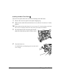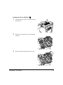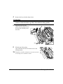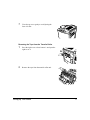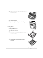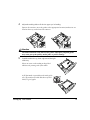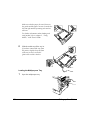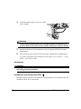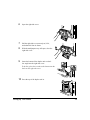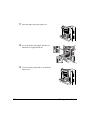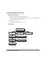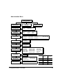
1
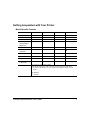
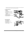
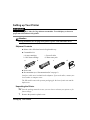
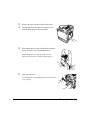
magicolor 2200
Installation Guide
®
1800615-001B
Thank You
Thank you for purchasing a magicolor 2200. You have made an excellent choice. Your magicolor 2200
is specially designed for optimal performance in Windows, Macintosh, and networking environments.
Trademarks
The following are registered trademarks of MINOLTA-QMS, Inc.: QMS, the MINOLTA-QMS logo,
and magicolor.
Minolta is a trademark of Minolta Co., Ltd. Other product names mentioned in this guide may also be
trademarks or registered trademarks of their respective owners.
Proprietary Statement
The digitally encoded software included with your printer is Copyrighted © 2000 by MINOLTA-QMS,
Inc. All Rights Reserved. This software may not be reproduced, modified, displayed, transferred, or
copied in any form or in any manner or on any media, in whole or in part, without the express written
permission of MINOLTA-QMS, Inc.
Copyright Notice
This guide is Copyrighted © 2000 by MINOLTA-QMS, Inc., One Magnum Pass, Mobile, AL 36618. All
Rights Reserved. This document may not be copied, in whole or part, nor transferred to any other
media or language, without written permission of MINOLTA-QMS, Inc.
Notice
MINOLTA-QMS, Inc. reserves the right to make changes to this guide and to the equipment described
herein without notice. Considerable effort has been made to ensure that this guide is free of
inaccuracies and omissions. However, MINOLTA-QMS, Inc. makes no warranty of any kind including,
but not limited to, any implied warranties of merchantability and fitness for a particular purpose with
regard to this guide. MINOLTA-QMS, Inc. assumes no responsibility for, or liability for, errors
contained in this guide or for incidental, special, or consequential damages arising out of the
furnishing of this guide, or the use of this guide in operating the equipment, or in connection with the
performance of the equipment when so operated.
Registering the Printer
Mail—Fill out and send in the registration card enclosed in your shipment.
Internet—www.qms.com/support/prodreg (US only)
Contents
Getting Acquainted with Your Printer ..........................................................................3
Model-Specific Features 3
Front/Right Side View 4
Front Internal View 4
Left Side/Rear Side View 5
Lower Feeder Unit (Standard with DP Model) 5
Duplex Unit (Standard with DP Model) 5
Documentation Set ........................................................................................................6
Setting up Your Printer .................................................................................................7
Shipment Contents 7
Unpacking the Printer 7
Loading Media 18
Accessories 22
Installing a Lower Feeder Unit (LFU) 22
Installing a Duplex Unit 27
Installing More Accessories 31
Plugging in/Turning on the Printer .............................................................................32
Configuration Menu Overview ...................................................................................33
Menu Chart Conventions 33
Security Menu 33
Operator Control Menu 34
Administration Menu 35
Administration/Communications/Resident NIC/CrownNet Menu 36
Selecting a Language ..................................................................................................36
Printer Control Panel 36
Software Utilities CD-ROM 37
About the Control Panel .............................................................................................38
Control Panel Indicators 38
Control Panel Keys 39
About the Interface Panel ............................................................................................40
Connecting the Printer ................................................................................................40
Utilities ........................................................................................................................41
Installing Printer Drivers and Software ......................................................................42
Windows Using TCP/IP 42
NetWare 5.x—IPX/NDPS 43
NetWare 5.x—IP/NDPS 46
Macintosh 48
Troubleshooting ..........................................................................................................50
Solving Problems during Installation 50
Accessories and Consumables ....................................................................................55
Accessories 55
Consumables 56
Regulatory Compliance ..............................................................................................57
FCC Compliance Statement 58
EN 55022 59
Canadian Users Notice 59
Laser Safety 59
International Notices 60
Warranty Considerations ............................................................................................60
Consumables and Your Warranty 61
Manufacturer’s Declaration of Conformity—Europe .................................................62
Manufacturer’s Declaration of Conformity—Latin America 110 Volt ......................63
Manufacturer’s Declaration of Conformity—Latin America 220 Volt ......................64
2
Getting Acquainted with Your Printer
Model-Specific Features
Features/Model
N
GN
EN
DP
Print Speed
5/20*
5/20*
5/20*
5/20*
SDRAM
64 MB
128 MB
128 MB
256 MB
Resolution
600 x 600 dpi
1200 x 1200 dpi
1200 x 1200 dpi
1200 x 1200 dpi**
500-sheet Letter/
A4/Legal Upper
Media Tray
z
z
z
z
Multipurpose Tray
z
z
z
z
Internal IDE
Hard Disk
•
•
z
z
Time-of-Day Clock
•
•
z
z
Lower Feeder Unit
•
•
•
z
Duplex Unit
•
•
•
z
Number of Cartons
in Shipment
1
1
1
3***
Notes
*5 = color; 20 = monochrome black.
**Full-speed duplexing at 1200 x 1200 dpi printing with most media sizes.
***If you don’t receive all 3 cartons, contact your shipping company or local
vendor.
z = Standard
• = Optional
Getting Acquainted with Your Printer
3
The drawings on these pages illustrate the parts of your printer referred to throughout this
guide, so please take some time to become familiar with them.
Front/Right Side View
1—Output tray
2—Top cover
3—Top cover latch
4—Control panel and message window
5—Front cover latch (one on each side)
6—Front cover
7—Upper media tray (tray also known as
a cassette)
8—Right-side cover latch
9—Multipurpose tray (closed)
10—Pull-out carrying bars (one on each side)
11—Upper feed path cover
c
d
e
f
g
h
j
k
i
l
11
Front Internal View
1—Toner ejection lever
2—Toner cartridge slot
3—Toner carrousel release button
4—Toner rotation knob
5—Waste toner pack
6—Transfer belt unit right release lever
7—OPC drum cartridge
g
c
d
h
i
e
f
4
Getting Acquainted with Your Printer
Left Side/Rear Side View
1—Ventilation grille
2—Interface panel
3—Main power switch
4—Top cover
5—Output tray
6—AC power connector
7—Hand grips for moving printer
8—Media tray (left side)
f
g
h
c
i
d
e
j
Lower Feeder Unit (Standard with DP Model)
1—Front cover
2—Upper media tray (also called
a cassette)
3—Lower feeder unit with media tray
4—Upper feed path cover
5—Lower feed path cover
The lower feeder unit has grips on all four corners. When moving the printer with a lower
feeder unit attached, hold the printer only by the
lower feeder unit grips, not by the printer body.
c
d
e
f
g
Duplex Unit (Standard with DP Model)
1—Front cover
2—Right-side cover
release
3—Duplex unit
4—Multipurpose tray
Getting Acquainted with Your Printer
c
d
e
f
5
Documentation Set
Your magicolor 2200 comes with two CD-ROMs. All the documentation is on the
Documentation CD-ROM unless otherwise noted below. It is provided in Adobe Acrobat
PDF format.
You may discover movie camera icons in the manuals. If you’re using the Acrobat
PDF version of this guide, click the icon to play a QuickTime video clip of the
procedure described in the text.
Quick Setup
Guide
Use this sheet when unpacking the printer (US only).
Service &
Support Guide
This lists global sources of service and support for your printer. Further information about MINOLTA-QMS printers is available through the Internet.
Installation
Guide
You’re looking at this document right now. This assists in setting up the printer,
installing a printer driver, and connecting to a network. It also briefly describes
the control panel and configuration menu.
User’s Guide
The User’s Guide guides you through the day-to-day operation of your printer,
including information on printing files, refilling print media, and replacing toner. It
also includes information on handling, cleaning, and maintaining your printer;
improving print quality; and troubleshooting printer problems.
Maintenance
Guide
This guide is a handy item to keep at the printer for quick reference information
regarding operation and care of the printer.
CrownBook
This manual provides detailed information about Crown architecture, color printing, menu configuration, and advanced computer/network connection and configuration. It can be found in PDF format on the Software Utilities CD-ROM.
Registration
Card
Registration and warranty information is included.
Colorific
Calibration
Card, Color
Encore
Brochure
These cards and brochure are used to color calibrate your printer and monitor.
Colorific User’s This manual contains instructions for using Colorific’s monitor calibration softManual
ware and helpful information about color management, ICC profiles, and color
matching. It can be found in PDF format on the Software Utilities CD-ROM.
6
Documentation Set
Setting up Your Printer
WARNING!
The printer weighs 87.1 lbs (39.5 kg) without consumables. To avoid injury, at least two
people must lift and move the printer.
Attention
During installation, do not plug in the printer’s power cord until told to do so.
Shipment Contents
z Printer with a 500-sheet letter/A4/legal media tray
z Consumables kit
a 4 toner cartridges
b OPC drum cartridge
a
c Fuser oil roller
d Waste toner pack
b
c
d
z Power cord
z Documentation (see “Documentation Set” on page 6)
Interface cables aren’t included in the shipment. If you need cables, contact your
local vendor or computer store.
The DP model comes with separate packaging for the lower feeder unit and the
duplex unit.
Unpacking the Printer
5" Save the packing materials in case you ever have to relocate your printer or for
future storage.
1
Remove the protective plastic cover.
Setting up Your Printer
7
2
3
Remove the tape from the outside of the printer.
Take the tape off of the pull-out carrying bars c
and slide them outward from the printer.
c
c
4
With another person’s help, lift the printer from the
carton, and place it in its intended location.
When lifting and carrying the printer, use the
pull-out carrying bars c and the hand grips d.
d
c
5
Open the front cover.
Use both hands to avoid putting uneven strain on the
cover’s hinge.
8
Setting up Your Printer
6
Remove the cardboard/foam spacers c and
the tape d from the laser lens cover.
c
d
5" The transfer belt left release lever will move to
the 4 o’clock position when you remove the
spacers. You will reposition the lever when you
install the OPC drum cartridge.
7
Press on the transfer belt unit front handle with
one hand, take the yellow handle of the transfer
belt unit fixture with your other hand, and pull
the fixture straight toward you.
This fixture protects the transfer belt during initial transportation.
5" Dispose of it according to your local
regulations.
Installing the Toner Cartridges
Your printer uses four toner cartridges: cyan, magenta, yellow, and black.
Setting up Your Printer
9
5"
The toner is nontoxic. If you get toner on your hands, wash them in cool water. If you
get toner on your clothes, lightly dust them off as much as possible. If some toner
remains on your clothes, use cool, not hot water, to rinse the toner off, provided your
clothing is washable.
WARNING!
If you get toner in your eyes, wash it out immediately with cool water and consult a doctor.
Material Safety Data Sheets (MSDS) information can be found at www.minolta-qms.com
(click on the Answer Base).
1
Remove the toner cartridges from their
packaging.
Attention
Do not touch the toner roller surface c or move the
protective shutter d away. This could lower image
quality.
c
d
Do not hold the toner cartridge vertically.
Each toner cartridge has a colored end that corresponds to a colored display label inside the slots in
the cartridge carrousel. Always install the toner
cartridge in the slot with a label of the same color.
10
Setting up Your Printer
2
Holding a cartridge with both hands, gently rock it from side-to-side five or six
times to distribute the toner.
3
Press the toner cartridge carrousel button
c and release the button d before turning the
carrousel dial e counterclockwise until it
stops.
2
The carrousel rotates 90° and stops.
5" The toner cartridge carrousel may start to turn
1
3
automatically from the weight of the inserted
toner cartridge. Make sure you have fully
turned to the next slot before trying to insert
another toner cartridge.
4
Place the front end of the two toner cartridge
guides into the two cartridge guide rails on
the cartridge carrousel and gently push the
cartridge into the printer until it is fully
inserted.
Attention
If a toner cartridge doesn’t slide in easily, don’t force it.
5
Repeat steps 2 through 4 until all the toner cartridges are installed.
5" New cartridges have a “break-in” period of 10–20 sheets before maximum print
quality is achieved.
Setting up Your Printer
11
Installing the OPC Drum Cartridge
The OPC (Organic Photo Conductor) drum cartridge forms the image that is developed
and transferred to the media.
Attention
The OPC drum is extremely sensitive to bright light and direct sunlight. Always
leave it in its protective bag until you’re ready to install it. Any exposure to light
should be avoided, or permanent damage could result. Also, handle the cartridge
carefully by its sides so you don’t touch the surface (the green part) of the drum.
The drum is extremely sensitive to hand oils and scratches, both of which reduce
print quality. This type of damage is not covered by the product warranty.
12
1
Rotate the transfer belt unit left release lever
counterclockwise to the top (12 o’clock)
position to raise the transfer belt unit.
2
Holding the OPC drum cartridge level,
place the front end of the cartridge
guide in the guide rail.
Setting up Your Printer
3
Push the OPC drum cartridge into the printer until
it is firmly seated.
Attention
The cartridge should slide easily into the printer. Don’t force it.
4
Press on the front handle of the drum cartridge with one hand and pull the handle of
the OPC drum protective sheet straight toward you with the other hand.
5" Dispose of it according to your local regulations.
5
Turn the left release lever of the transfer belt
unit clockwise to its correct (2 o’clock) position
to lower the transfer belt unit.
Setting up Your Printer
13
Installing the Waste Toner Pack
The waste toner pack collects the excess toner remaining on the OPC drum.
1
2
Remove the waste toner pack from its plastic shipping bag.
Make sure the transfer belt unit left release lever is still set to its correct (2 o’clock)
position.
5" If the transfer belt unit left release lever is at its top (12 o’clock) position or the laser
lens cover is not firmly seated, the waste toner pack cannot be installed.
3
Press the bottom of the waste toner pack into the
printer first, then the top, until it is firmly seated.
2
1
4
Close the front cover.
Use both hands to avoid putting uneven strain on the
cover’s hinge.
14
Setting up Your Printer
Installing the Fuser Oil Roller
1
Push the top cover latch c to open the top of
the printer d.
d
c
2
Rotate the two small levers to the unlocked
position.
3
Remove the tape from the media exit area.
Setting up Your Printer
15
4
Remove the fuser oil roller from its box.
Attention
Lift and hold the fuser oil roller only by the handle. Do not allow the roller
surface to contact the table or get dirty. This could lower image quality.
5
Insert the fuser oil roller
guides into the guide rails (see
arrows), then carefully lower
the roller.
6
With the top of the printer
open, rotate the two fuser oil roller levers to the
locked position.
5" If the fuser oil roller release levers are not correctly
set, the top cover cannot be closed.
16
Setting up Your Printer
7
Close the top cover gently to avoid jarring the
fuser oil roller.
Removing the Tape from the Transfer Roller
1
Press the right cover release button c and open the
right cover d.
c
d
2
Remove the tape from the transfer roller unit.
Setting up Your Printer
17
3
Make sure the transfer roller unit handles remain in
their down position.
4
Close the right cover.
The printer is ready for loading media and installing accessories.
Loading Media
Loading the Media Tray
18
1
2
Slide out the media tray.
3
Push the media pressure plate down to lock it
in position.
Remove the tape and the packing material from the
media pressure plate.
Setting up Your Printer
4
Adjust the media guides to fit the size paper you’re loading.
Squeeze the retainers, move the guides to the appropriate location (media sizes are
listed on the tray), and release the retainers.
Attention
The media should fit easily between the guides. Improperly adjusted guides
may cause poor print quality, media jams, or printer damage.
5
Load the media face-up, short edge toward the right
of the tray.
Often, an arrow on the media package label
indicates the printing-side of the media.
A fill limit mark is provided on the inside of the
tray. The media tray holds 500 sheets of 20 lb
bond (75 g/m²) paper.
Setting up Your Printer
19
Make sure that the paper fits easily between
the guides and the paper corners are under the
left and right media-separating tabs and are
not bent.
For further information about loading and
using media, refer to chapter 2, “Using
Media,” in the User’s Guide.
6
Slide the media tray all the way in.
If you have removed the tray from
the printer, slightly tilt up the front
of the tray to insert it into the
guide rails to slide it back in.
Loading the Multipurpose Tray
1
20
Open the multipurpose tray.
Setting up Your Printer
Open the media support.
3
Load the media face down, short
edge toward the printer.
Often, an arrow on the media
package label indicates the
face-up side of the media.
FA
C
DO E
WN
2
A fill limit mark is provided on
the inside of the media guides on the multipurpose tray. The multipurpose tray holds
150 sheets of 20 lb bond (75 g/m²) paper.
Attention
Load only one type or size of media per tray at a time.
Setting up Your Printer
21
4
Adjust the media guides to fit the size media
you’re loading.
LTR
LG .
EXE. L.
A5
B5
A4
Attention
Always adjust the media guides after inserting the media. A guide that is not
properly adjusted can cause poor print quality, media jams, or printer damage.
5
Specify the media size in the multipurpose tray by using the MP Size key on the
control panel.
6
Print at least 20 pages to make sure the new toner cartridges have settled properly.
For further information about loading and using media, refer to chapter 2, “Using
Media,” in the User’s Guide.
Accessories
Attention
Installing accessories always requires that the printer and accessories are turned off
and unplugged during installation.
Installing a Lower Feeder Unit (LFU)
Read this section if you have a DP model or if you purchased a lower feeder unit for your
magicolor 2200 N, GN, or EN model.
22
Setting up Your Printer
Kit Contents
„
Lower feeder unit with a letter/A4/
legal media tray (500 sheets)
„
3 metal brackets
— Bracket L (1)
L
R
B
— Bracket R (1)
— Bracket B (1)
„
2 securing thumbscrews
Installation
Attention
If consumables are installed in the printer, be sure to keep the printer level when
moving it to prevent accidental spills.
If your printer is located in its permanent location, follow this procedure. Otherwise, skip
to step 3.
1
Pull out the two carrying bars on the right side of
the printer.
WARNING!
The printer weighs 103.4 lbs (47.4 kg) with consumables and media. To avoid injury, at least
two people must lift and move the printer.
2
With one person holding the carrying bars and another holding the two grips on the
left side of the printer, lift the printer and temporarily move it to a flat, level surface.
Setting up Your Printer
23
3
Remove the lower feeder unit from the shipping carton, and place it where the
printer will be located.
4
5
6
Slide out the optional media tray from lower feeder unit.
7
Slide the optional media tray all the way
into the lower feeder unit.
Remove any tape and packing material.
Put media in the optional tray.
5" If you have removed the tray from the lower
feeder unit, slightly tilt up the front of the tray to
insert it into the guide rails to slide it back in.
8
24
Slightly tilt up the printer’s upper media tray to
remove it.
Setting up Your Printer
9
With another person’s help, lift the printer.
When lifting and carrying the printer, use the
pull-out carrying bars c and the hand grips d.
d
c
10
Slowly lower the printer onto the lower
feeder unit, lining up the four holes in the
bottom of the printer with the corresponding pins in the lower feeder unit.
11
Place bracket L on the left side of the
printer frame and secure it tightly with the
thumbscrew.
Setting up Your Printer
25
12
Hold bracket R on a slant to insert it from
the front end into the bracket R slot on the
right side of the printer frame, then hold
bracket R level and secure it tightly with
the thumbscrew.
13
Unscrew the thumbscrew from the rear of
the printer.
5" Retain this screw for use in step 15.
14
26
Hold bracket B on a slant and insert the front
end into the bracket B slot.
Setting up Your Printer
15
Lift up bracket B and secure it tightly with the
thumbscrew.
Make sure the bracket matches the position shown
in the illustration.
16
Slide the upper media tray back into the printer.
Installing a Duplex Unit
Read this section if your printer is a magicolor 2200 model DP or if you purchased a
duplex unit for your magicolor 2200 model N, GN, or EN.
Kit Contents
„
Duplex unit
„
2 thumbscrews
Installation
1
2
Remove the duplex unit from its shipping box.
Remove the tape from the unit.
Setting up Your Printer
27
3
Open the multipurpose tray.
4
Remove the two thumbscrews from the right
side cover.
5" Retain these screws in case you need to
remove the duplex unit in the future.
5
28
Press the right-side cover release button.
Setting up Your Printer
6
Open the right-side cover.
7
Pull the right-side cover toward you, lift it,
and unhook it from its frame.
8
With the multipurpose tray still open, close the
right-side cover.
9
Insert the bottom of the duplex unit at a shallow angle into the right-side cover.
To do this, place the two tabs at the bottom into the
holes on the right-side cover.
10
Press the top of the duplex unit in.
Setting up Your Printer
29
30
11
Open the duplex unit paper path cover.
12
Secure the duplex unit tightly with the two
thumbscrews supplied in the kit.
13
Close the duplex paper path cover and multipurpose tray.
Setting up Your Printer
14
Open the right-side cover.
15
Extend the spring wire for the duplex unit
about 1 foot (30.5 cm).
16
Attach the end of the spring wire to the hook
on the printer unit.
17
Close the right-side cover.
Installing More Accessories
If you purchased any additional printer accessories, then install them now. If installation
instructions are included with the accessory, follow them. If not, instructions are included
in the User’s Guide.
A complete list is in “Accessories and Consumables” on page 55. Refer to
www.minolta-qms.com for part numbers and pricing.
Setting up Your Printer
31
Plugging in/Turning on the Printer
1 Make sure the printer is turned off.
2 Plug the printer power cord into the
printer and into the dedicated,
grounded, surge-protected electrical
outlet.
WARNING!
Do not overload the outlet. For products installed outside North America, do not connect the
groundwire to gas or water pipes or grounding for telephones.
3
Turn on the printer.
After a brief warmup, your printer prints a startup page
and displays “IDLE” on the message window. If
“IDLE” is not displayed in the message window after the
power switch is turned on, the setup operation is not proceeding correctly or the printer may be malfunctioning.
Recheck the setup. If the startup page doesn’t print or the
print quality is not good, skip ahead to “Troubleshooting” on page 50.
5" The printer automatically switches to power-saving mode after 60 minutes of
inactivity. In the Administration/Engine/Energy Saver menu, you can change the
number of minutes before the printer switches to power-saving mode.
5" In compliance with UL guidelines, “The appliance inlet is considered to be the main
disconnect device.”
32
Plugging in/Turning on the Printer
Configuration Menu Overview
Menu Chart Conventions
The following conventions are used in the menu charts:
„
Some menu choices are marked as optional, indicating that the selection appears in the
menu only when the option is installed.
„
Defaults are bolded.
For more menu details, refer to the User’s Guide.
Security Menu
Configuration
Security
Operator Control
Operator Menu
Set Password, Enable Password
Admin Menu
Set Password, Enable Password
Administration
Security Passwrd
Configuration Menu Overview
33
Operator Control Menu
Configuration
Operator Control
Copies
Off, Long Edge, Short Edge
Outputbin
Upper, Mailbin1*...Mailbin5*
Chain Mail Bin*
Off, On
Collation
Off, On
Inputbin
Security
001-999
Duplex**
Orientation
Portrait, Landscape
Multipurpose, Upper, Optional*
Chain Inputbins
Off, On
Multipurpose Sz
Letter, Legal, A4, UK Quarto, Foolscap, Folio, SP Folio, Executive, B5 JIS, A5,
Statement, B5 ISO, C5, DL, Com10, C6, Monarch, Postcard, GT Postcard
Color Separation
Off, On
Color Model
Full Color, Monochrome
Media Mode
Single User Mode, Network Mode
Color Matching
Media
Accounting***
Proof-Then-Print***
Consumables
34
Administration
ICC RGB Source, ICC Simulation, ICC Destination,
ICC PCL Source, Link Quality, SIM in RGB Links
For MPT Bin, For Upper Bin, For Optional Bin*
Mode, Disk Space,
ResetAccounting, File Segment
File Name1
Item Replaced, Print Statistics
* Optional
** Standard on DP models
***Only with a hard disk installed
Configuration Menu Overview
Administration Menu
Configuration
Administration
Communications
Emulations
Special Pages
Startup Options
Memory
Engine
Consumables
Security
Operator Control
Timeouts
Parallel
Resident NIC
Optional NIC*
ESP Default
TIFF**
CALS**
PostScript
PCL 5e
HP-GL
Print Status
Registration Pg
Header Page
Lineprinter
CGM***
LN03+*
Trailer Page
Header Inputbin
Trailer Inputbin
CMM Profile Page
Test Page 1
Test Page 2
Do Start Page
Do Sys Start
Do Error Handler
Manual Config***
Enable Disk Swap***
Quick Config***
Image Alignment
Rotate Simplex
Default Paper
Inputbin 1 Name
Inputbin 2 Name
Inputbin 5 Name*
Outputbin Name****
Toner Low2Act.
Outputbin
Name*
Energy Saver
Outputbin
3 Name*
Def.
Resolution
Outputbin 4 Name*
Maintenance
Outputbin 5 Name*
Outputbin 6 Name*
Def. Resolution
Page Recovery
Energy Saver
Toner Low Action
AIDC Mode
Density
*
Start Period
Service
Optional
** Only with ImageServer installed
***
Miscellaneous
Disk Operations***
Calibration Page
Status Page Type
Save Defaults
Restore Defaults
Reboot System
New System Image
Capture PrintJob***
Keypad Language
Clock Operations*
Format Disk, Backup Hard Disk, Restore Disk
Optional, Requires
a Hard Disk
CGM
X
Disk Operations
X
Enable Disk
Swap
X
Manual Config
X
Optional, Does Not
Require a Hard
Disk
Quick Config
X
X
****With a 5-bin mailbox installed, Outputbin Name
becomes Outputbin 1 Name*
Configuration Menu Overview
35
Administration/Communications/Resident NIC/CrownNet Menu
Idle
Configuration
Administration
Communications
Optional NIC
CrownNet
Common
Mode
Resident NIC
Emulation
EtherTalk
Min K Spool
LAN Manager
Def Job Prio
NetWare
PS Protocol
TCP/IP
Selecting a Language
Printer Control Panel
The control panel message window provides status and configuration information. Status
messages and configuration menus can be displayed in the message window in Czech,
Danish, Dutch, English, French, German, Italian, Japanese, Portuguese, and Spanish.
When you receive your magicolor 2200, the language is set to English. If you want to
change the message window language, use the following quick control panel sequence
(slightly dependent upon the model and installed options):
36
Press Key
(Until) Display Reads
Online
IDLE (and online LED is off)
Menu
OPERATOR CONTROL
Selecting a Language
Press Key
(Until) Display Reads
Next (
ADMINISTRATION
)
Select
Previous (
ADMINISTRATION–COMMUNICATIONS
ADMINISTRATION—MISCELLANEOUS
)
Select
Previous (
MISCELLANEOUS—SAVE DEFAULTS
MISCELLANEOUS—KEYPAD LANGUAGE
)
Select
Next (
KEYPAD LANGUAGE—*ENGLISH
)/Previous (
)
Select
5"
Press the Next and/or Previous key until the language required
is displayed
<LANGUAGE> IS SELECTED
The printer must be restarted for changes to the Keypad Language menu to take effect.
You can either let the printer restart automatically after you save the change and exit
from the Configuration menu, or you can wait for the change to take effect the next time
you manually turn on the printer.
Software Utilities CD-ROM
The Software Utilities CD-ROM is
equipped with an auto-start program. It
automatically starts up in one of the
available languages on the Software
Utilities CD-ROM. In a Windows
environment, you may change the opening
language by changing the computer’s
Regional Settings (double-click on the My
Computer icon, then on Control Panel,
then on Regional Settings).
5" Other applications on your PC may
also be affected by changing the
Regional Settings.
Selecting a Language
37
About the Control Panel
The control panel, located on the front of the printer, allows you to direct the printer’s
operation. In addition, it displays the current status of the printer, including any condition
that needs your attention. The control panel consists of the following parts:
„
Three indicators (LEDs) to provide printer status information.
„
A message window to display status and configuration information.
„
Seven keys to allow you to control the printer configuration through access to
frequently used printer functions.
MESSAGE
WINDOW
Control Panel Indicators
Indicator
Off
On
The printer is off
The printer is on line and ready to accept data.
line and not ready
to accept data.
38
The printer is not
receiving data.
The printer is receiving data from one or more of its interfaces.
No problem.
The printer requires operator attention (usually accompanied
by a status message in the message window).
About the Control Panel
Control Panel Keys
Key
Function
MP SIZE Use the MP Size key to set the multipurpose tray to the correct media size.
The MP Size key on the Control Panel must be used in conjunction with setting the size in the driver.
Accesses the configuration menu. When you’re changing the printer configuration, press this key to cancel a change (before pressing the Select keys), to
return to the previous selection or option for the current menu and to return to
the previous choice when changing character information.
The Select key accesses a menu or chooses a displayed menu option,
advancing to the next selection or option for the current menu and advancing
to the next choice when changing character information.
The Online key switches the printer between online and offline status. Press
the key once to take the printer off line when it is on line, and press the key
once to return the printer to on line when it is off line. When off line, the printer
continues printing until it has finished all jobs received, but it doesn’t accept
any new data. Although jobs continue to compile and print using the data
already received, a job may be interrupted. If a remote console has taken the
printer offline, pressing the Online key on the control panel will not take effect
until the remote console puts the printer back on line.
The Cancel key allows you to cancel one or all print jobs or to end a job. If the
printer is on line, press the Cancel key to cancel the job currently printing. If
you press the Cancel key by mistake, or if you decide not to cancel a print job
after pressing this key, press the Cancel key to “cancel” the Cancel key’s
function.
Previous/Next navigation keys allow you go backward or forward through the
menu choices.
About the Control Panel
Press
Online
First?
No
Yes
N/A
N/A
No
Yes
39
About the Interface Panel
The interface panel is located on the left back of
the printer.
Parallel connection
Using a Centronics IEEE 1284 bidirectional parallel cable, connect the
parallel port on the printer to the
parallel port on your computer.
Optional SCSI port
Parallel port
Ethernet port
Optional interface port
Ethernet connection
Using a twisted-pair (RJ45) Ethernet
cable, connect the Ethernet port on the printer to a 10BaseT/100BaseTX
network connection.
Connecting the Printer
If you’re replacing a printer, you may already have a printer cable. If not, contact your
local vendor or computer store.
1
2
3
Turn the printer off.
Install the printer cable.
Turn the printer on.
5" In compliance with UL guidelines, “The appliance inlet is considered to be the main
disconnect device.”
40
About the Interface Panel
Utilities
These are your utilities that are available for your printer, and this is what they’re used for:
Utilities
Utility
Use/Benefit
PostScript Driver for Me/
98/95
This driver gives you access to all of the printer features, including
finishing, color management, and advanced layout on the Windows
Me/98/95 platform. It is designed to be both feature-rich while versatile and easy to use.
PostScript Driver for 2000/
NT4
This driver gives you access to all of the printer features, including
finishing, color management, and advanced layout on the Windows
2000/NT4 platform. It is designed to be both feature-rich while versatile and easy to use.
PostScript Printer
Definitions
These PPD files allow you to install the printer for a variety of platforms, drivers, and applications.
Print Monitor for Windows
This Windows utility gives an efficient serverless method for transporting print jobs directly to a MINOLTA-QMS printer via the TCP/IP
protocol. the Print Monitor functions on Windows Me/98/95 as well
as Windows 2000/NT4.
Profile Downloader
This utility allows the user to download color profiles from a Windows
workstation to the printer’s hard disk.
CrownView
This utility, designed with users in mind, is an HTML-based web
page, residing in the MINOLTA-QMS printer, that provides printer
status, job status, and printer configuration information via a web
browser from any platform.
CrownAdmin
This utility, designed with administrators in mind, is a powerful tool
allowing centralized management of all the Crown printers on your
network. It is available for WIndow, Macintosh, and UNIX platforms.
UNIX Host Software
The UNIX Host Software, compatible with a variety of UNIX platforms, allows for the customization of UNIX-based queues and filters
for the specific features of the Crown printer.
Printer Utility for the
Macintosh
This utility provides common management tasks for Crown printers
from a Macintosh platform, such as naming printer, downloading of
fonts, and configuration.
41
Installing Printer Drivers and Software
Windows Using TCP/IP
TCP/IP Interface Configuration
Detailed instructions for configuring TCP/IP can be found in the CrownBook.
5" If you use DHCP to configure TCP/IP, you must enable DHCP/WINS in
Administration/Communications/Resident NIC/CrownNet/TCP/IP printer
configuration menu.
You can configure your print system by several different methods. This section briefly
describes the configuration procedure for the printer interface. You can make these
configuration changes through any of the following means:
„
Printer control panel
„
CrownAdmin 3 for Windows
„
Remote Console through a telnet session
1
If necessary, in the Administration/Communications/Resident NIC/CrownNet/
TCPIP/Internet Address menu, enter the printer’s Internet address.
The factory default Internet address is 161.033.128.024.
2
If necessary, in the Administration/Communications/Resident NIC/CrownNet/
TCPIP/Default Router menu, enter the Internet address of the default router.
The factory default router address is 000.000.000.000. This setting provides
automatic sensing of gateways. If you identify a subnet mask, automatic sensing
is disabled.
3
If necessary, in the Administration/Communications/Resident NIC/CrownNet/
TCPIP/Subnet Mask menu, enter the printer’s subnet mask.
The default subnet mask is 000.000.000.000.
TCP/IP Network Configuration
1
42
Log on the system as administrator.
Installing Printer Drivers and Software
2
Edit the system host table by adding the following line to the host file:
internetaddress hostname
where internetaddress is the Internet address of the printer (Administration/Communications/Resident NIC/CrownNet/TCPIP/Internet Address menu, and hostname is
the descriptive name of the printer.
3
Go to the Software Utilities CD-ROM. It will autolaunch. Follow the instructions on
the screen.
NetWare 5.x—IPX/NDPS
IPX Interface Configuration
5"
1
2
3
4
In CrownAdmin 3, the printer shows up as QMS-xxx-Print-Systemhardwareaddress, where xxxx is the printer model number and
hardwareaddress is the printer’s hardware address as found
on the printer startup page.
In the main CrownAdmin 3 window, select the printer you want to configure.
Click the Printers Option button to display a list of printers.
Click the NetWare 3.x button.
In the list of options, highlight (NDS) PServer Context.
Installing Printer Drivers and Software
43
5
In the Edit Settings text box, enter the File Server name and print server context in
all caps).
5" This must match the one assigned using NWAdmin.
z File server name
z Space
z Print server context
For example, if the configuration file server name is QMS-4 and the print server
context is PRINTSERV2.SALES.QMS, you would enter:
QMS-4 PRINTSERV2.SALES.QMS
5" Make sure to put a space between the file server name (QMS-4) and the print server
context (PRINTSERV2.SALES.QMS).
5" If you are asked to enter a password, enter “ADMIN.”
Network Configuration
The following steps detail the necessary configuration on your NetWare server.
Create Broker (If Necessary)
1
2
3
4
5
6
Open NW Admin and select the container where you want to place the broker.
7
Load the Broker at the Server console by typing
Select Object and click Create.
Select NDPS Broker and click OK.
Type in the name for the NDPS Broker.
Select the volume where the broker will reside and click the Create button.
Check the configuration for access control to make sure that the Administrator is on
the list.
Load broker “.<broker name>.<context where broker resides>”
44
Installing Printer Drivers and Software
Create NDPS Manager (If Necessary)
1
2
3
4
5
In NWAdmin, select the container where you want to place the manager.
6
7
Click the Create button.
8
Load the NDPS Manager at the Server console by typing
Select Object and click Create.
Select the NDPS Manager and click OK.
Type in the name for the NDPS Manager.
Select the resident server and the Database Volume (usually in the server’s
SYS volume.)
Check the configuration for access control to make sure that the Administrator is on
the list.
Load ndpsm “<NDPS manager name>”
9
Check the Server console for the Windows “Printer Agent List”.
Create Printer Agent
1
2
3
4
5
6
7
In NWAdmin, select the container where you want to place the Printer Agent.
8
9
10
Configure the Port Handler for the new Printer Agent.
Select Object and click Create.
Select NDPS Printer and click OK.
Type in the name for the Printer Agent’s name and click the Create button.
Select the NDPS Manager. Browse if necessary.
Select Novell Printer Gateway and click OK.
Select the MINOLTA-QMS Print System to use with the Printer Agent and click the
OK button. (If your printer is not listed, select the Generic PS printer.)
Select Forward Jobs to a queue and click the Next button.
Click the Queue Name button and select the print queue defined for the print system.
Installing Printer Drivers and Software
45
11
12
Click the Queue User Name button and select the user from the list.
Click the Finish button.
5" On the Server’s console the Administrator password must be entered in order to load
the Printer Agent.
13
Select the printer drivers for the different operating system and click the Continue
button.
14
Check the information box for the selected drivers.
The printer and network configuration is now complete. For individual workstation driver
installation, refer to the appropriate chapter in this manual for instructions on installing
drivers, host software, or other utilities.
NetWare 5.x—IP/NDPS
TCP/IP Interface Configuration
Detailed instructions for configuring TCP/IP can be found in the CrownBook.
5" If you use DHCP to configure TCP/IP, you must enable DHCP/WINS in
Administration/Communications/Resident NIC/CrownNet/TCP/IP printer
configuration menu.
You can configure your print system by several different methods. This section briefly
describes the configuration procedure for the printer interface. You can make these
configuration changes through any of the following means:
„
Printer control panel
„
CrownAdmin 3 for Windows
„
Remote Console through a telnet session
1
If necessary, in the Administration/Communications/Resident NIC/CrownNet/
TCPIP/Internet Address menu, enter the printer’s Internet address.
The factory default Internet address is 161.033.128.024.
2
46
If necessary, in the Administration/Communications/Resident NIC/CrownNet/
TCPIP/Default Router menu, enter the Internet address of the default router.
Installing Printer Drivers and Software
The factory default router address is 000.000.000.000. This setting provides automatic sensing of gateways. If you identify a subnet mask, automatic sensing is disabled.
3
If necessary, in the Administration/Communications/Resident NIC/CrownNet/
TCPIP/Subnet Mask menu, enter the printer’s subnet mask.
The default subnet mask is 000.000.000.000.
4
5
Log on the system as administrator.
Edit the system host table by adding the following line to the \windows\hosts file:
internetaddress hostname
where internetaddress is the Internet address of the printer (Administration/Communications/Resident NIC/CrownNet/TCPIP/Internet Address menu, and hostname is
the descriptive name of the printer.
Network Configuration
This assumes that an NDPS broker object and an NDPS manager object are already
created. If not, see instructions on page 44.
1
From your browser’s Object menu for the Organization or Organizational unit,
select Create.
2
3
In the New Object dialog box, select NDPS Printer.
4
At the Printer Agent Source field, select Create a New Printer Agent and
click Create.
5
6
7
Browse to select the NDPS Manager you want to assign it to.
In the Create NDPS Printer dialog box. type the name of your printer in the Printer
Name field.
At the Gateway Types window, select the Novell gateway and click OK.
In the Novell PDS dialog box, configure the Novell PDS by selecting the Printer
Type and Port Handler Type and click OK.
The Configure Novell Port Handler Wizard appears.
8
Configure the Connection Type as Remote (LPR on IP) and click Next.
Installing Printer Drivers and Software
47
9
Type in the Host Address, or Host Name, and Printer Name.
5" The default is "Passthrough."
The new Printer Agent loads.
10
If you choose, select the printer driver for each client workstation and click
Continue.
The main browser window appears listing your new controlled access printer.
Macintosh
EtherTalk Interface Configuration
You can configure your MINOLTA-QMS print system by several different methods.
This section briefly describes the configuration procedure for the printer interface. Refer
to your printer documentation for detailed instructions. You can make these configuration
changes through any of the following means:
„
Printer control panel
„
CrownAdmin 3 for Macintosh
„
Print Utility for Macintosh
„
Remote Console
„
CrownView
When your printer boots up, it will find a default zone. If your network has more than one
zone, use the Administration/Communications/Resident NIC/CrownNet/EtherTalk/Zone
Name/Zone Part 1 and Zone Part 2 menus to enter the name of the zone to which the
printer is attached.
5" The two Zone Part x menus allow you to identify 1 zone with a name up to 32
characters long. (Up to 16 characters can be entered in each of the two menus). You
cannot use these two menus to identify two zones. Trailing spaces are not considered
part of the zone name. All standard printable ASCII characters are valid except the
@ and ' symbols. The names are case sensitive.
48
Installing Printer Drivers and Software
Installing Macintosh PPDs and Utilities
1
Insert the autoloading Software Utilities CD-ROM.
5" Open the Readme file in the Explore button for information on the latest available
drivers, PPDs, and utilities.
2
3
Double-click the INSTALL icon.
Follow the instructions on the screen.
Installing Printer Drivers and Software
49
Troubleshooting
Although the magicolor 2200 is designed to be highly reliable, you may occasionally
experience a problem. The following helps you to identify the cause of the possible
installation problems and suggests some solutions related to installation. For detailed
troubleshooting information, refer to “Troubleshooting” in the User’s Guide.
Solving Problems during Installation
Symptom
Cause
Solution
No lights or
messages
appear on
the control
panel.
There is no power supplied to the AC outlet.
Make sure there is power supplied to the AC outlet.
The power cord is not
plugged in securely into
both the power outlet and
the printer.
Make sure the power cord in plugged in securely both at
the power outlet and the printer.
The printer power switch is Turn the printer power switch to the On (I) position.
not in the On (I) position.
The line voltage from the
Make sure the line voltage matches the printer’s power
power outlet doesn’t match requirements.
the printer’s power requirements.
You can’t
Is the printer off line before Turn the printer off line before printing a status page.
print a status you try to enter the Adminpage.
istration/Special Pages/
Print Status menu?
The tray does not have
media.
Check that the media trays are loaded with media, in
place and secure.
The printer’s covers aren’t Make sure the front and top covers are closed securely.
closed securely.
Close all covers gently to avoid jarring the printer. Make
sure the waste toner pack in installed correctly.
There is a media jam.
50
Check for a media jam.
Troubleshooting
Symptom
Cause
Solution
The printer is
not receiving
data from the
computer.
(The Data
indicator
doesn’t blink
after a file is
sent.)
The printer is not on line.
Put the printer on line and check if the message window
displays IDLE.
The emulation has been
changed from ESP to an
emulation that doesn’t
match the file you are
sending.
Print a status page from the control panel.
The printer is
printing
codes or not
printing at all
when in ESP
mode.
The printer emulation is not Reconfigure the port to the specific printer emulation of
correct.
the file you are trying to print.
Top cover
does not
close.
The fuser oil roller release Open the top cover and turn the fuser oil roller release
lever is not set in the cor- lever (two locations) to the locked position, then close
rect position.
the cover gently to avoid jarring the printer.
Front cover
does not
close.
The transfer belt right
release lever is not set in
the correct position.
Turn the right release lever clockwise to the 10 o’clock
position, then close the front cover.
The waste toner is not set
correctly.
Remove the waste toner, then reinstall it correctly.
Troubleshooting
Your ESP timeout is too
short.
If a PostScript file prints PostScript statements while the
printer is in ESP mode, increase the ESP timeout.
If you continue to have problems with the ESP mode
selecting the appropriate printer emulation, contact
Technical Support. Refer to the Service & Support
Guide.
51
Symptom
Cause
Solution
The Online
indicator is
on and the
message in
the display is
“IDLE,” but
no startup
page prints.
You did not wait long
enough.
Did you wait long enough? From a cold start, the printer
takes approximately 3 minutes to warm up.
Be sure you wait long enough for a startup page before
suspecting a problem.
Print startup is not enabled. Make sure the option to print startup is enabled in
Administration/Startup Options/Do Startup Page.
The defaults have been
changed.
Perform a restore defaults on the printer.
From your control panel, select Administration/Miscellaneous/Restore Defaults/Factory Defaults/Yes.
Can you print a simple sentence such as “This is a test.”
from a simple application on your computer (for example, WordPad or Notepad)? From your start menu on
your computer, select Start/Programs/Accessories/
WordPad.
You haven’t rebooted the
printer.
Waste toner
pack cannot
be installed.
Reboot the printer and reprint the job. Do you get an
error page?
The transfer belt left
Turn the left release lever clockwise to the 2 o’clock
release lever is not set cor- position, then install the waste toner.
rectly.
The laser lens cover is not Reinstall the laser lens cover.
installed, or was not
installed correctly.
The toner cartridge carrou- Turn the carrousel dial counterclockwise.
Toner cartridge carrou- sel dial is turned clockwise.
sel will not
turn.
Toner carThe toner cartridge carrou- Press and release the carrousel release button, the turn
tridge carrou- sel release button was not the carrousel dial counterclockwise.
pressed.
sel dial will
not turn.
52
Toner carA toner cartridge was not
tridge carrou- inserted in that slot.
sel slot is
empty.
Press the toner release button and turn the carrousel
dial until you reach the empty slot. You do not have to
load the toner in a set sequence.
Fuser oil
The fuser release lever is
roller cannot not set in the correct posibe installed. tion.
Turn the left release lever clockwise to the 12 o’clock
position, then install the fuser oil roller.
Troubleshooting
Symptom
Cause
Solution
OPC drum
unit cannot
be installed.
The transfer belt left
release lever is not set to
the OPC drum installation
position.
Turn the left release lever counterclockwise to the 12
o’clock position, then install the OPC drum unit.
Startup page Media improperly aligned
comes out
in tray or bad media.
skewed.
Check media in trays.
CHECK
The waste toner pack isn’t Make sure the waste toner pack sits snugly against the
WASTE
properly installed.
printer.
TONER message
appears in
the message
window.
Printer power The power cord is not
is not on.
correctly plugged into the
outlet.
The power switch is not
correctly turned on (I
position).
Turn the power switch off (O position), then remove the
power cord from the outlet and plug it back in.
Set the power switch to the off (O) position, then set it
back to the on (I) position.
Something is wrong with
Plug another electrical appliance into the outlet and see
the outlet you are using for whether it operates properly.
the printer.
The printer is connected to Check the voltage and frequency of the outlet. Use a
an outlet with a voltage or power source with the following specifications:
—Power
frequency that does not
Japan: 100 VAC 50–60 Hz 12 amps
match the printer specificaNorth America: 120 VAC 50–60 Hz 8 amps
tions.
Europe: 220-240 VAC 50–60 Hz 6 amps
Latin America: 120 VAC 50–60 Hz 8 amps
220-240 VAC 50–60 Hz 6 amps
—Voltage fluctuation
Japan: 100 VAC ±10%
North America: 120 VAC ±10%
Europe: 220-240 VAC ±10%
Latin America: 120 VAC ±10%
220-240 VAC ±10%
—Frequency fluctuation rate within 50/60 ±3 Hz
Troubleshooting
53
Symptom
Cause
Solution
Error message is displayed.
A consumable item, such
as paper or toner, has run
out.
Handle the message according to the message display.
A unit or tray is not correctly installed.
The media is jammed.
A problem occurred inside
the printer.
Print is
unclear.
54
New toner cartridge(s) has
(have) been installed, but
the “break-in” period has
not been reached.
Print at least 20 pages to make sure the new toner
cartridges have settled properly.
Troubleshooting
Accessories and Consumables
Accessories
Refer to www.minolta-qms.com for part numbers and pricing.
Description
Remark(s)
5-bin Mailbox
Three models: For 100-, 120-, or 220-volt printers
Automatic Document Feeder (ADF) for
SC-210
Optional ADF for convenience copier.
BuzzBox
Via parallel connection for 100, 120, and 220 volts
CGM
Optional emulation
CrownNet for Ethernet 10BaseT/100BaseTX Equipped with RJ45 connector
Interface
CrownNet for Token-RIng Interface
Equipped with STP and UTP connectors
Crown for DECnet-TCP/IP Interface
Equipped with 10BaseT
Dual In-Line Memory Modules (DIMMs)
Additional memory must be 32, 64, or 128 MB,
PC-100 Compliant SDRAM DIMMs, up to a printer
maximum of 384 MB.
Duplex Unit
Standard with model DP
ImageServer
Optional TIFF/CALS
Internal IDE Hard Disk Drive
Standard with models EN and DP
Kanji Font Internal IDE Hard Disk
Includes seven fonts
LN03
Optional emulation
LocalTalk Interface
Equipped with LocalTalk
Lower Feeder Unit
Media tray included. Standard with model DP
Media Tray, 500 Sheet
Purchasing extra trays may be convenient when
changing media formats and/or media qualities vary.
Planet Press
Form-creation utility
Printer Stand/Cabinet
Tabletop or floor model
QFORM
Form-creation utility
SC-210 Convenience Copier
SC-210 Color Convenience Copier
SCSI Interface
Up to 3 SCSI interfaces allowed
Time-of-Day Clock
Standard with models EN and DP
Accessories and Consumables
55
Consumables
Refer to www.minolta-qms.com for part numbers and pricing.
Description
Remark(s)
Fuser oil roller
FUSER OIL LOW, FUSER OIL EMPTY, or REPLACE OIL
ROLLER displays in the message window (after up to 21,000
single-sided continuous monochrome or 7,500 continuous color
pages, or 7,000 intermittent monochrome or 5,000 intermittent
color pages). Heavy coverage, intermittent printing, and different
media types can use up oil at an accelerated rate, reducing fuser
oil roller life.
Fuser unit/transfer roller kit
REPLACE FUSER displays in the message window (after 100,000
single-sided pages maximum at an equal mix of black and 4-color
pages, all with 5% coverage of each color; however, fuser unit life
is coverage and media dependent).
OPC drum kit (OPC drum car- REPLACE DRUM, CHECK WASTE TONER, WASTE TONER NEAR
FULL, or REPLACE WASTE TONER displays in the message wintridge, laser lens cover, and
waste toner pack)
dow (up to 30,000 continuous monochrome or 7,500 continuous
four-color pages, or 10,000 intermittent monochrome or 5,000
intermittent color pages). Other factors also affect cartridge life.
Toner cartridge
<COLOR> TONER EMPTY displays in the message window (after
approximately 6,000 single-sided pages per cartridge—black,
yellow, magenta, cyan at 5% coverage of each color).
Transfer belt
REPLACE TRANSFER BELT displays in the message window
(after 107,000 pages continuous monochrome or 33,000 continuous color pages, or 44,000 intermittent monochrome or 23,000
intermittent color pages).
5"
56
Consumable life is expressed in simplex letter/A4 pages. A duplex page is equivalent to
two simplex pages.
Accessories and Consumables
Regulatory Compliance
CE Marking and
Immunity
Requirements
(EU)
International (EU)
EN 55024
EN 50081-1
EN 61000-3-2
EN 61000-3-3
IEC 61000-4-2
IEC 61000-4-3
IEC 61000-4-4
IEC 61000-4-5
IEC 61000-4-6
IEC 61000-4-8
IEC 61000-4-11
Immunity Characteristics
Generic Emission Standard
Harmonic Current Emissions
Voltage Fluctuations and Flicker
ESD
Radiated Susceptibility
Fast Transients
Surge Immunity
Immunity to Conducted Disturbance
Magnetic Field Immunity
Voltage Dips and Variations
cTick Mark
ACA (Australia)
AS/NZS 4251
AS/NZS 3458
Generic Emissions Standard
ITE
Electromagnetic
Emissions (EMI)
FCC (USA)
Title 47 CFR Ch. I, Part 15
Industry Canada (Canada)
ICES-003 Issue 3
International (EU)
EN 55022
VCCI (Japan)
VCCI V-1/98.04
Energy Saver
ENERGY STAR (USA)
Regulatory Compliance
Class B Digital Device
(Class A Digital Device with
Token-Ring or LocalTalk interface
installed)
Class B Digital Device
(Class A Digital Device with
Token-Ring or LocalTalk interface
installed)
Class B ITE
(Class A Digital Device with
Token-Ring interface installed)
Class B ITE
(Class A Digital Device with LocalTalk
interface installed)
ENERGY STAR Compliant
57
Product Safety
UL (USA)|
cUL (Canada)
UL 1950, Third Edition
CAN/CSA C22.2 No. 950-93
TUV/GS and CB
Scheme
International (EU)
EN 60950 and IEC 60950
Laser Safety
CDRH (USA)
Title 21 CFR Ch. I, Subchapter J
International (EU)
EN 60825-1
FCC Compliance Statement
This equipment has been tested and found to comply with the limits for a Class B digital
device, pursuant to Part 15 of the FCC Rules. These limits are designed to provide
reasonable protection against harmful interference in a residential installation. This
equipment generates, uses, and can radiate radio frequency energy and, if not installed and
used in accordance with the instruction, may cause harmful interference to radio
communications. However, there is not guarantee that interference will not occur in a
particular installation. If this equipment does cause harmful interference to radio or
television reception, which can be determined by turning the equipment off and on, the
user is encouraged to try to correct the interference by one or more of the following
measures:
„
Reorient or relocate the receiving antenna
„
Increase the separation between the equipment and receiver
„
Connect the equipment into an outlet on a circuit different from that to which the
receiver is connected
„
Consult the dealer or an experienced radio/TV technician for help
5"
5"
A shielded cable is required to comply with the limits for a Class B digital device,
pursuant to Part 15 of the FCC Rules.
This is a Class B device, but with the optional Token-Ring or LocalTalk optional
interfaces installed, it changes to a Class A device.
This equipment has been tested and found to comply with the limits for a Class A digital
device, pursuant to Part 15 of the FCC Rules. These limits are designed to provide
reasonable protection against harmful interference in a commercial environment. This
equipment generates, uses, and can radiate radio frequency energy, and if not installed and
used in accordance with the instruction manual, may cause harmful interference to radio
58
Regulatory Compliance
communications. Operation of this equipment in a residential area is likely to cause
harmful interference, in which case the user will be required to correct the interference at
his/her own expense.
Attention
Any modifications or changes to this product not expressly approved in writing by
the manufacturer responsible for compliance to Federal Regulations could void the
user's authority to operate this product within the Laws and Regulations of the
Federal Communications Commission.
EN 55022
Attention
On the 220 volt printer, this Class B product becomes a Class A product with the
addition of an optional Token-Ring interface. In a domestic environment, this
product may cause radio interference in which case the user may be required to take
adequate measures.
Canadian Users Notice
This Class B digital apparatus complies with Canadian ICES-003.
Cet appareil numérique de la classe B est conforme à la norme NMB-003 du Canada.
5"
This is a Class B device, but with the optional Token-Ring and LocalTalk optional
interfaces installed, it changes to a Class A device.
This Class A digital apparatus complies with Canadian ICES-003.
Cet appareil numérique de la classe A est conforme à la norme NMB-003 du Canada.
Laser Safety
This printer is certified as a Class 1 laser product under the U.S. Department of Health and
Human Services (DHHS) Radiation Performance Standard according to the Radiation
Control for Health and Safety Act of 1968. This means that the printer does not produce
hazardous laser radiation.
Regulatory Compliance
59
Since radiation emitted inside the printer is completely confined within protective
housings and external covers, the laser beam cannot escape from the machine during any
phase of user operation.
International Notices
Power Cord
The following power cord requirements are in effect for the 220v magicolor 2200.
Minimum
Minimum
0.75 mm
2
H05 VV - F
„
The male plug is certified in the country in which the equipment is to be
installed, and the female plug is an IEC 320 connector.
Voltage
Attention Norwegian users: This equipment is designed to operate within an IT power
system where the line-to-line voltage does not exceed 240v.
Lithium Batteries
Attention Swiss users: Lithium batteries need to be disposed of in accordance with
Annex 4.1 of SR814.013.
Warranty Considerations
Various factors can affect a printer’s warranty. Two important ones are consumables
and electrostatic discharge. Read your printer warranty carefully.
5"
Don’t return any merchandise to the manufacturer without calling for a return
merchandise authorization (RMA) number. Refer to the Service & Support Guide for the
Support telephone number where you can obtain an RMA number.
If you have any questions, refer to www.minolta-qms.com.
60
Warranty Considerations
Consumables and Your Warranty
Use of consumables not manufactured by MINOLTA-QMS or use of non-supported print
media may cause damage to your printer and void your warranty. If MINOLTA-QMS
printer failure or damage is found to be directly attributable to the use of nonMINOLTA-QMS consumables and/or accessories, MINOLTA-QMS will not repair the
printer free of charge. In this case, standard time and material charges will be applied to
service your printer for that particular failure or damage.
To order consumables and accessories, go to www.q-shop.com or check the Service &
Support Guide for the MINOLTA-QMS office closest to you.
Warranty Considerations
61
Manufacturer’s Declaration of Conformity—Europe
We:
MINOLTA-QMS Europe B.V.
(supplier’s name)
Reactorweg 160, 3542 AD Utrecht, The Netherlands
(address)
declare under our sole responsibility that the product
magicolor 2200
(base product family name)
MC2200-2
(model number located on dataplate)
4120
(print engine model/type number)
to which this declaration relates is in conformity with the following standard(s) or other
normative document(s)
EN 60950:1992+A1+A2+A3+A4+A11, CB Scheme in accordance with
IEC 60950:1991+A1:1992+A2:1993+A3:1995+A4:1996,
CB Certificate No. US-TUVR-0562
EN 60825-1:1994+A11, EN 55022:1998, EN 55024:1998,
EN 61000-3-2:1995+A1:1997+A2:1998, EN 61000-3-3:1995,
IEC 61000-4-2: 1995+A1:1998
IEC 61000-4-3:1995+A1:1998, IEC 61000-4-4:1995, IEC 61000-4-5:1995,
IEC 61000-4-6:1996, IEC 61000-4-8:1993 and IEC 61000-4-11:1994
(title and/or and number and date of issue of the standard(s) or other normative document(s))
(if applicable) following the provisions of 73/23/EEC, 89/336/EEC Directive(s).
Utrecht, The Netherlands—September, 2000
(place and date of issue)
62
Manufacturer’s Declaration of Conformity—Europe
Manufacturer’s Declaration of Conformity—Latin
America 110 Volt
We:
MINOLTA-QMS, Inc.
(supplier’s name)
One Magnum Pass, Mobile, Alabama, USA, 36618
(address)
declare under our sole responsibility that the product
magicolor 2200
(base product family name)
MC2200-1
(model number located on dataplate)
4120
(print engine model/type number)
to which this declaration relates is in conformity with the following standard(s) or other
normative document(s)
UL 1950 Third Edition, 1995; cUL CAN/CSA C22.2 No. 950-M95;
FCC Class B Digital Device Title 47 CFR Ch. I., Part 15;
FCC Class A Digital Device Title 47 CFR Ch. I., Part 15 applies for systems
configured with Token-Ring or LocalTalk interface installed;
Industry Canada ICES-003 Issue 3 Class B Digital Device;
Industry Canada ICES-003 Issue 3 Class A Digital Device applies for systems
configured with Token-Ring or LocalTalk interface installed;
EPA ENERGY STAR Office Equipment Program;
CDRH Laser Safety Title 21 CFR Ch. I., Subchapter J;
MSDS Title 29 CFR Ch. XVII, Part 1910.1200.
(title and/or and number and date of issue of the standard(s) or other normative document(s))
(if applicable) following the provisions of N/A Directive(s).
Mobile, Alabama, USA—September, 2000
(place and date of issue)
Manufacturer’s Declaration of Conformity—Latin America 110 Volt
63
Manufacturer’s Declaration of Conformity—Latin
America 220 Volt
We:
MINOLTA-QMS, Inc.
(supplier’s name)
One Magnum Pass, Mobile, Alabama, USA, 36618
(address)
declare under our sole responsibility that the product
magicolor 2200
(base product family name)
MC2200-2
(model number located on dataplate)
4120
(print engine model/type number)
to which this declaration relates is in conformity with the following standard(s) or other
normative document(s)
EN 60950:1992+A1+A2+A3+A4+A11, CB Scheme in accordance with
IEC 60950:1991+A1:1992+A2:1993+A3:1995+A4:1996,
CB Certificate No. US-TUVR-0562
EN 60825-1:1994+A11, EN 55022:1998, EN 55024:1998,
EN 61000-3-2:1995+A1:1997+A2:1998, EN 61000-3-3:1995,
IEC 61000-4-2:1995+A1:1998,
IEC 61000-4-3:1995+A1:1998, IEC 61000-4-4:1995, IEC 61000-4-5:1995,
IEC 61000-4-6:1996, IEC 61000-4-8:1993, and IEC 61000-4-11:1994
(title and/or and number and date of issue of the standard(s) or other normative document(s))
(if applicable) following the provisions of 73/23/EEC, 89/336/EEC Directive(s).
Mobile, Alabama, USA—September, 2000
(place and date of issue)
64
Manufacturer’s Declaration of Conformity—Latin America 220 Volt
Index
A
Accessories 55
Duplex unit 27
Installation 22
Lower input feeder 22
Other 31
Administration menu 35
Administration/Communications/Resident NIC/
CrownNet menu 36
Auto-start CD-ROM 37
B
BuzzBox 55
C
Cancel key 39
Carrousel also known as a rack 4
Carrying bars 8
Cassette (see tray) 4
Cautions
OPC drum cartridge 12
Class A device 58
Class B device 58
Common menu 36
Configuration menu
Administration 33
Operator Control 33
Overview 33
Connecting
Ethernet cable 40
Parallel cable 40
Printer 40
Consumables 56
Warranty 61
Control panel 38
Control keys 38
Data indicator 38
Message indicator 38
Message window 38
Online indicator 38
Status indicators 38
Convience copier 55
I
EN 55022 59
Ethernet
Connection 40
EtherTalk 48
Interface Configuration 48
Indicators
Message 38
Online 38
Installation
Accessories 22
Duplex unit 27
Lower feeder unit 22
Macintosh utilities 49
Media tray
Loading 18
OPC drum cartridge 12
PPDs 49
Removing the transfer belt unit fixture 9
Toner cartridges 9
Waste toner pack 14
Interface Configuration
EtherTalk 48
TCP/IP for Windows Me/98/95 42, 46
International notices
Notices
International 60
IP/NDPS Configuration 46
F
L
FCC
Class A 58
Class B 58
Compliance 58
FCC
Caution 59
Fuser oil roller 15
Lanuages
Selecting via CD-ROM 37
Laser
Lens cover 14
Radiation confined 59
Safety 59
Laser lens cover 14
Lithium batteries 60
Loading
Media tray 18
Multipurpose tray 20
Lower feeder unit
Installation 22
D
Data indicator 38
Default subnet mask 42, 47
DHCP
For configuring TCP/IP,
Windows Me/98/95 42, 46
DHCP/WINS menu configuration
Windows Me/98/95 42, 46
Documentation 6
Duplex unit 5, 27
E
G
Getting acquainted with your printer 3
H
Host computer 40
64
M
P
Macintosh
EtherTalk Interface Configuration 48
Installing 48
Manufacturer’s Declaration of Conformity
120 volt 63
220 volt 64
Europe 62
Media 18
Multipurpose tray 20
Media cassette 4
Fill limit mark 19, 21
Media key 39
Media pressure plate 18
Media tray 4
Upper media tray 18
Menu configuration
DHCP/WINS
Windows Me/98/95 42, 46
Menus 36
Message indicator 38
Message window 36
Multipurpose tray 20
Parallel
Connection 40
PDF format 6
Power cord 32
PPDs
Installing 49
Printer
Creating a printer ageny 45
Getting acquainted 3
Plugging in 32
Status 38
Turning the printer on 32
Unpacking 3, 7
N
NDPS Configuration 43
NDPS Manager, creating a 45
Norwegian user voltage notice 60
Notices
Canadian users 59
Norwegian user voltage 60
Swiss lithium batteries 60
O
Online indicator 38
Online key 39
OPC drum cartridge
Cautions 12
Removing protective sheet 13
Operator Control menu 34
R
Rack (see carrousel) 4
Radiation confined 59
Relocating your printer 8
S
Security menu 33
Subnet mask
Default 42, 47
Swiss lithium batteries notice 60
T
TCP/IP
Configuring with DHCP,
Windows Me/98/95 42, 46
Interface Configuration for
Windows Me/98/95 42, 46
Toner
Cartridge 9
Distributing toner in the cartridge 9
Installation 9
Loading-no sequence 52
Transfer belt unit 14
Left release lever 14
Right release lever 14
Transfer belt unit fixture 9
65
Transfer roller 17
Tray 4
Loading 18
Media tray 18
Tray also known as a cassette 4
Troubleshooting
Printer problem checklist 50
W
Warranty 61
Waste toner pack 14
Installation 14
66