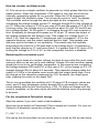
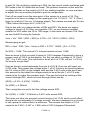
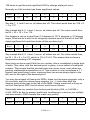
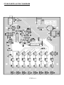
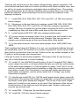
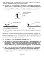
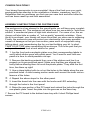
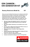
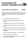
1
COMPUTEMP 255 BINARY THERMOMETER KIT Ramsey Electronics Model No. CT255 A really neat educational kit to learn the principles of binary math, how simple digital to analog converters work, and how instrumentation amplifiers may be used to measure the environment. • Visibly counts up to the current temperature in binary numbers ! • Eye catching display, great for home or office • Super accurate readout of +-1 degree Celsius, no calibration required ! • Precision sensor, designed with remote sensing option • Resurrected Ramsey kit from the past; build something your Dad built 20 years ago! • Jumper settings for Fahrenheit or Celsius temperature scales • Range of 0-127.5 degrees Celsius in 1/2 degree steps. (32—261.5 F) • Runs from 7-15VDC. CT255 • 1 RAMSEY TRANSMITTER KITS • FM100B Professional FM Stereo Transmitter • FM25B Synthesized Stereo FM Transmitter • MR6 Model Rocket Tracking Transmitter • TV6 Television Transmitter RAMSEY RECEIVER KITS • FR1 FM Broadcast Receiver • AR1 Aircraft Band Receiver • SR1 Shortwave Receiver • SC1 Shortwave Converter RAMSEY HOBBY KITS • SG7 Personal Speed Radar • SS70A Speech Scrambler • BS1 “Bullshooter” Digital Voice Storage Unit • AVS10 Automatic Sequential Video Switcher • WCT20 Cable Wizard Cable Tracer • ECG1 Heart Monitor Kit • PG13 Plasma Generator Kit • IG7 Ion Generator Kit • R2XL1 Balanced to Unbalanced Audio Converter Kit • LC1 Inductance-Capacitance Meter RAMSEY AMATEUR RADIO KITS • HR Series HF All Mode Receivers • QRP Series HF CW Transmitters • CW7 CW Keyer • CPO3 Code Practice Oscillator • QRP Power Amplifiers RAMSEY MINI-KITS Many other kits are available for hobby, school, Scouts and just plain FUN. New kits are always under development. Write or call for our free Ramsey catalog. COMPUTEMP 255 KIT INSTRUCTION MANUAL Ramsey Electronics publication No. MCT255 Rev 1.1a First printing: November 2001 COPYRIGHT 2001 by Ramsey Electronics, Inc. 590 Fishers Station Drive, Victor, New York 14564. All rights reserved. No portion of this publication may be copied or duplicated without the written permission of Ramsey Electronics, Inc. Printed in the United States of America. CT255 • 2 Ramsey Publication No. MCT255 Price $5.00 KIT ASSEMBLY AND INSTRUCTION MANUAL FOR COMPUTEMP 255 BINARY THERMOMETER KIT TABLE OF CONTENTS Introduction ...................................... 4 Circuit Description ............................ 5 Schematic Diagram.......................... 13 Parts Layout Diagram ...................... 14 Parts List .......................................... 15 Assembly Instructions ...................... 17 Case Assembly ................................ 23 Troubleshooting Guide..................... 25 Conclusion ....................................... 26 Warranty .......................................... 27 RAMSEY ELECTRONICS, INC. 590 Fishers Station Drive Victor, New York 14564 Phone (585) 924-4560 Fax (585) 924-4555 www.ramseykits.com CT255 • 3 INTRODUCTION Years ago Ramsey Electronics had a really neat little kit called the CompuTemp 127. This was a favorite kit purchased by many who were into the electronics hobby in the ‘70s and ‘80s. It was unfortunately retired to make space for a growing list of other popular kits being added to the catalog at the time. This is an original drawing (touched up) from the original 6 page manual showing the stylish kit case that John Ramsey had spent his hard-earned money on the die for when he was fresh out of college. We have come a long way since then! CR4 LENS F IL T E R C R10 U3 P .C . B O A R D F R O N T V IE W O F P C B B O A R D IN C A S E At the time, this case was one of the only good looking extrusion cases that a hobbyist could use for his projects. Now there are a huge variety to choose from. Hobbyists have no idea how good they have it! A very popular kit at the time, we have brought it back for your enjoyment. It makes a great conversational piece too! CT255 • 4 CIRCUIT DESCRIPTION There’s a lot of circuitry in the CT255 that is in use to this day in a variety of circuits. We will begin with the temperature sensor itself, detailing how we did this 20 years ago and how we do it now. The actual temperature sensor is the LM35DZ. It is a specialized part that is pre-calibrated at the factory to output 10mV per degree Celsius. For example if we connected the part to power and measured the output at 0 degrees Celsius, the output would be 0mV. If the temperature were then raised to 50 degrees Celsius, the output would become 500mV, which is 10mV * 50C. Really simple isn’t it? In the past we used a diode junction to do the sensing, because a diode junction has a very predictable change of voltage drop versus temperature. In the case of silicon, this drop works out to be 2.1mV for every degree Celsius. Unfortunately using diodes caused us to use calibration to compensate for offset and gain, which was a real pain. Now it comes down to needing to display this output in a form our eyes can understand, and this means driving a display. In our case we will be displaying the value in a way that both humans and computers can understand: binary. How do we do this easily? Hang on, here we go… The binary counter U2:A and U2:B form a cascading ripple counter which is simply designed to count pulses on the clock pin (pin 1), and output the count as binary. The high order bit of U2:A (pin 6) is then tied to the clock input of U2:B to make an 8 bit counter in total. A binary counter is a very simple set of flip-flops that are fed from one to another in sequence. The lowest order (bit 0) is tied to the input of the next (bit 1) and the output of bit 1 is tied to the input of bit 2 and so on. For every two pulses on the input to the flip flop, the output switches once. When the flip flops are cascaded, they make a “ripple” counter, meaning all outputs are effected by the single input, but all in succession, not simultaneously. When we put the kit together, this count sequence will make much more sense since you can see it occur! The binary count is then tied to a resistor “ladder”. Believe it or not, this makes a very simple digital to analog converter! As the count increases on the outputs of U2, the voltage increases in a linear step across R38 and C5. This is set up here to be an eight bit digital to analog converter. Many digital to analog converters use a ladder style resistor network just like this. To increase number of bits, they just use more precision on the resistors, and increase the count. CT255 • 5 The DAC (Digital to Analog Converter) The resistor values in this ladder are chosen to give us nice even steps in the voltage range we are able to work with. The outputs of the counter can’t actually achieve 5 volts with the LEDs on the output, but really close at 4.67V. We then figure what the voltage will be across R38 when all outputs of the counter are at 4.67V and we will have the maximum output of our DAC. In this case it is 3.10V. Of course the minimum works out to be 0V. To find our minimum resolution we find the number of steps the counter has, which is in this case 2^8 which is 256 possibilities. 0 is one of them, so take 3.10V and divide by 255 to come up with 12.16mV per step or count. This means this is the smallest change in voltage that we can measure with our DAC. When the counter is counting up, you can take a volt meter, probe R38 and see the voltage “ramp” up with the count. On an oscilloscope, you can not only see the voltage ramp up, but also take 255 steps on the way up to 3.10V, each step being 12.16mV! It’s worth it just to check this. The ADC (Analog to Digital Converter? In a sense…) Well, you may wonder how this ramp from our counters and resistor ladder can be used to display temperature. This will be done in a way many analog to digital converters used to make conversions. ADCs use much more complicated methods now to increase conversion speed, but that is beyond this manual. Now you know that each count is equal to 12.16mV, so if you have a count of 100, you should have an output of 1.216V from our DAC. Well this means that the display should also be indicating 100 degrees Celsius, right? This also means that our temperature sensor should be putting out 1.216V at 100 degrees Celsius to get this count of 100, but it doesn’t since it only outputs at 10mV per degree Celsius, which would only be 1.00V. This means we need to scale the output of the temperature sensor to meet the needs of our DAC so the count display and the voltages match. Scaling to Celsius To scale the output, we just have to figure out what it will take to make 1.00V become 1.216V. Not too tough here, we just multiply our 1.00V by 1.216. But wait, we’re going to make things complicated. We want to display temperature in 1/2 degree increments. This means that we have to multiply the sensor output by 2 to multiply our reading by 2. In this case we need 1.216 x 2 or a gain of 2.422. Since the display has a potential count of 255, and we will never find an air temperature of 255 degrees Celsius (and like it), we can divide the display by 2 to scale it to the range of 0-127.5 and use the last LED for 1/2 degree steps. U1:A is set up as a non-inverting amplifier, and the output of the temperature sensor is sent to the non-inverting input (pin 3) to be amplified. R39 and C6 are CT255 • 6 in series with the input to reduce any noise that may be present on the temperature sensor to increase accuracy of your reading. C3 in the feedback branch is also used to reduce noise in the reading. In the Celsius jumper setting, R37 and R27 are used to adjust the gain of our temperature sensor for a Celsius reading. The gain of a non-inverting amplifier is calculated by the formula : A = 1 + Rf / Ri. Where Rf if the feedback resistor R27, and Ri is the input resistor R37. (Even though the input isn’t at R37, it is considered that for mathematical purposes). So looking at the values in the circuit: A = 1 + 1430 / 1000 or A = 2.43 As you can see this is very close to our requirement of 2.422, which is more than close enough for +-1 degree C resolution. More on the ADC To stop the count when the output voltage of our temperature scaling amplifier matches the count of our ripple counter DAC, we use a circuit called a comparator. A simple op-amp makes an excellent comparator, as shown by U1:B. When the voltage at pin 5 is above the voltage at pin 6, the output at pin 7 goes as high as possible, in this case about 3.9V. When the voltage at pin 5 is below the voltage at pin 6, the output goes as low as possible, or zero volts. It is called a comparator because it is in reality comparing two voltages, and giving you an output based on the difference. We employ this circuit to stop the count in our ripple counter as soon as its output voltage surpasses the output of our temperature sensor circuit. This allows us to take a reading from the display, and this is what a computer would see as a value for a complete Analog to Digital conversion! Oh that extra count! Ok, maybe you’re smart and figured out that for the count to stop, the output voltage of the DAC has to surpass the output of the temperature sensing circuit. This means that if your temperature is zero, and the count is at zero, the output of the DAC does not quite surpass the output of the temperature sensor. This means that the temperature reading will have to increment at least once to have a reading. This means that your temperature readings will at the most be high 0.5 degrees F or 0.5 degrees C depending the range you are in. However, on average it will only be 0.25 degrees high. All ADCs have this problem, and it is related to the bit resolution (in our case 8 bits). This is still within +-1C accuracy. CT255 • 7 How the counter oscillator works U1:D is set up as a simple oscillator to generate our clock pulses that drive the ripple counter. When the comparator U1:B output is low, this circuit will run normally, generating pulses for our counter. When the U1:B comparator output is high, the oscillator stops. This is how the count is “held” for display. This oscillator works through the same principle as the comparator, by comparing the charge voltage across C1 charged through R1 to the voltage at pin 12. When the output of U1:D is our max of 5V and the output of U1:B is 0V (running mode), the voltage at pin 12 should be about 3V (R4, R2 and R3 act as a voltage divider). At this point C1 is charging through R1 over a period of time. Eventually its charge will surpass our 3V at pin 12, where the output of the opamp comparator will switch to low. This makes our voltage at pin 12 about 1.6V. Now the capacitor C1 discharges until it surpasses 1.6V in the opposite direction, and the output switches back to high. This repeats over and over and is the basis of our oscillation. The reason why the oscillator stops when the output of U1:B goes high is the voltage at pin 12 becomes a level that the charge on C1 can never reach. It is greater than 5.0V due to R15 limiting the voltage on C1 to 3.4V, so the comparator function is disabled. Restarting the conversion cycle Now our count stops at a certain voltage, but how do we make the count reset every so often so we can get a new reading? Simple. We have another opamp stage that is set to be yet another comparator. In this case we are comparing the voltage between R30 and R34, in this case 2.5V, to the charge on C2. C2 charges through R24 in about 5-6 seconds. This capacitor charges while the output of U1:B is in the disable count mode with the output being high. Once the charge on the capacitor surpasses the 2.5V threshold, the output goes high, clearing the count on the ripple DAC. This in turn re-enables the oscillator of U1:D since U1:B compare values are reset, and C2 then discharges quickly through D9 to get ready for the next round starting with the first clock pulse in U1:D. C2 does not charge until the count is complete, so the reset cycle will hold the finished count long enough to be seen. For the complicated Fahrenheit design Skip this section if you don’t want a bad headache. Now how do we switch to Fahrenheit? Not a simple as it sounds. For one our Celsius to Fahrenheit conversion is listed as: F = 9/5 * C + 32 We see by this formula that not only do we have to scale by 9/5 we also have CT255 • 8 to add 32. We do this by switching in R22 into the circuit, which combined with R23 adds in the 32 offset that we need. The problem however is this acts like a voltage divider on the output of U1:A our scaling amplifier, so now we have to adjust the non-inverting amplifier’s gain to compensate. First off we need to set the zero point of the sensor to a count of 32. This requires us to have a voltage on the opamp pin 6 of 12.16mV * 32 * 2. (Don’t forget to scale by 2 for our 1/2 degree steps!) This means we need pin 6 to be 778mV when the output of U1:A is 0.0V. We do this with our voltage divider of R22 and R23. We know our supply voltage is close to 5.0V from our regulator VR1, so we choose a random resistor for R22 within the 1K to 10K range. In this case we choose 10K. Now we can find R23 using the formula: Vout = Vin * R23 / (R22 + R23) or 0.778 = 5.0 * R23 / (10000 + R23) Rearranging we get: R23 = Vout * R22 / (Vin—Vout) or R23 = 0.778 * 10000 / (5.0—0.778) So R23 = 1.84K. The closest 1% tolerant resistor is then 1.82K. Now we have to find out what it takes for 100.0 degrees Fahrenheit to have a proper count of 100.0 on the display. For this we need a voltage of 12.16mV * 100 * 2 or 2.432 volts. This will have to be at pin 6 of U1:B, not pin 1 of U1:A. So how do we get that? First we have to work backwards from pin 6 of U1:B. Here we will insert our 2.432 volts. This means the voltage at pin 1 of U1:A has to be found by taking the 5.0 volts on R22 on the header side and the 2.432 volts at the pin 6 side into account to find what the voltage needs to be at the pin 1 of U1:A side needs to be to make the numbers work. This can be found by looking at the current through R22, which is found through Ohms law by: I(R22) = (5.0V—2.432V) / 10000 = So I(R22) = 0.256mA Then using this current to find the voltage across R23. So V(R23) = 1.82K * 0.256mA or 0.467 volts across R23. This does not take into account current into pin 6 of U1:B, which could effect these levels considerably if it is large enough. We have designed in a nice rail to rail opamp to reduce this to a minimum. This means the output of U1:A needs to be 2.432—0.467 or 1.965 volts at 100.0 degrees Fahrenheit. CT255 • 9 At 100.0 degrees Fahrenheit the temperature sensor will have an output of a value related to Celsius, so to make life easier, we will convert to Celsius first. So: C = 5/9(F-32) or C = 5/9(100—32) which is 37.78 degrees Celsius. This means the output of the sensor should be 377.8mV at 100.0 F. So to convert 377.8mV to 1.965 volts we need to multiply by: 1.965 / 0.3778 or 5.201. This will be the gain we need from the non-inverting amplifier. We go back to our old non-inverting amplifier formula of: A = 1 + Rf / Ri, which is the gain of the non-inverting opamp. We already have Ri = 1.00K and A of 5.201 so we have to find Rf. Rearranging we get Rf = (A-1) * Ri so Rf = (5.201—1) * 1000 So Rf = 4.201K. Our closest 1% value is 4.22K. Binary math Oh no! Your brain hurts and doesn’t want any more theory; on to the kit building! Ok, go ahead and build the kit, but come back here later to review how to read the display properly, and why it works that way. Normally we would only deal with integer binary math, but we at Ramsey like to mix things up a bit, and throw in fractional binary math so you learn something new! It is the basis of how all math works on computers, including that pesky floating point stuff, especially on DSPs. We will also learn why computers are NOT perfectly accurate. A binary number is either 1 or 0, on or off, meaning it is only two states. Two LEDs will have 4 potential states, 3 will have 8 states, and 4 will have 16. The relationship is 2 to the power of the number of bits. This is seen as 2^n when n is the number of bits. In the case of our display we have 8 bits, so we have 2^8 or 256 potential states. As the value counts up, you will see the right most bit (LED) toggle the fastest. This LED is considered the least significant bit, meaning it has the least value associated with it. In our case it is worth a measly 0.5, but normally would be worth 1 if we didn’t throw in a decimal point to confuse you. The LED on the far left is called the most significant bit, because it is worth the most. In our case it is worth 64 but normally 128. This is because the .5 LED had to flash CT255 • 10 128 times to get the most significant LED to change state just once. Normally an 8 bit number has these significant values: Bit #: 7 6 5 4 3 2 1 0 Value: 128 64 32 16 8 4 2 1 Say bits 7, 3, and 0 are on, all others are off. The value would then be 128 + 8 + 1 or 137. Say instead bits 6, 5, 4 and 1 are on, all others are off. Our value would then be 64 + 32 + 16 + 2 or 114. Our display is set up to read from 0.0 degrees to 127.5 degrees in 1/2 degree steps. What we do is stick in an imaginary decimal point to the left of the LSB (least significant bit) and then divide all the numbers by 2. Bit #: 7 6 5 4 3 2 1 0 Value: 128/2 64/2 32/2 16/2 8/2 4/2 2/2 1/2 Say instead bits 6, 5, 4 and 1 are on, all others are off. Our value would then be 32 + 16 + 8 + 1 or 57, which is 1/2 of 114.0. This means that we have a temperature reading of 57 degrees! Now since we have used 8 bits for our counter, this is considered a single byte of data. This value, with the decimal point in place, is now called a fixed-point number. This means that the decimal point can never move, even when we perform mathematical operations on it. This number is now considered a 7.1 format fixed point binary value, meaning there are seven binary digits to the left, one to the right of the decimal point. You may have heard of fixed-point DSPs; these use the same principle, only a lot more bits, and the values never surpass 1 or –1 since they shift the decimal point all the way to the left of the MSB. If there were such a thing as an 8-bit fixed point DSP, the bit values would be as follows: Essentially take our number from before and divide by 256, or 144/256 = 0.445. DSPs do this to prevent math from overflowing in value as you multiply and accumulate. DSPs handle this math very quickly. Bit #: 7 6 Value: 128/256 26/256 5 4 3 2 1 0 32/256 16/256 8/256 4/256 2/256 1/256 CT255 • 11 You may notice though that the smallest step in this case is 1/256. This 8 bit DSP is unable to accurately represent this number smaller than 3.906E-3. Most fixed points DSPs however are 16 bit, 24 and 32 bits. 24 bits of resolution means the smallest number we can represent becomes 1/(2^24) which is 5.96E-8, which is considerably smaller and more accurate. Still the math isn’t perfect, and these “steps” will accumulate over time and cause errors. A 24 bit DSP number is usually in a 0.24 fixed point binary value, 0 bits to the left, 24 to the right of the decimal point. Some random parts, and what they do C5 has been added to the output of the ladder to “smooth” the steps slightly. U2, the 74HC393, is so fast at its job that when an output switches it causes a slight bit of overshoot. The overshoot turned out to be about the same voltage as a half of a degree reading, causing the reading to be incorrect sometimes. This capacitor fixed that. Imagine sanding the top corners of all of your stairs in a new staircase to smooth the freshly sawed edges. It looks similar to sanded steps on an oscilloscope. D10 is a rectifier diode. This diode converts our AC adapter input to DC, but only in what is called a half-wave rectifier. This means that only 1/2 of a complete AC cycle is used for powering the CT255. The CT255 does not require much power so a full-wave bridge circuit was not necessary. A full wave rectifier uses both halves of the AC cycle (negative and positive) for powering the circuit. C8 helps to average the pulses that the 1/2 rectifier creates allowing the 5 volt regulator VR1 to work properly. VR1 smoothes out our incoming supply power so that it is flat instead of looking like an ocean in a storm. C7 helps the regulator VR1 work a little better, so it is included. J1 allows you to whip up a cable with three wires and make an external sensor. When your external sensor is plugged in, it disables the internal sensor. CT255 • 12 CT255 SCHEMATIC DIAGRAM CT255 • 13 CT255 PARTS LAYOUT DIAGRAM CT255 • 14 PARTS SUPPLIED WITH YOUR CT255 KIT Capacitors 4 .1 µF disc capacitor (marked .1 or 104 or 100 nF) [C3,4,5,6] 1 1 µF electrolytic capacitors [C1] 2 10 µF electrolytic capacitors [C2,7] 1 470 µF electrolytic capacitor [C8] Resistors 8 390 ohms (orange-white-brown) [R5,6,7,8,9,10,11,12] 1 1K ohms (brown-black-red) [R39] 13 10K ohms (brown-black-orange) [R2,3,4,17,19,21,26,29,30,33, 34,36,40] 10 20K ohms (red-black-orange) [R13,14,16,18,20,25,28,32,35,38] 1 47K ohms (yellow-violet-orange) [R1] 1 100K ohms (brown-black-yellow) [R15] 1 1M ohms (brown-black-green) [R24] Precision Resistors (with five color code bands or SMT) 1 1K ohms (brown-black-black-brown) [R37] 1 1.43K ohms (brown-yellow-orange-brown-brown) [R27] 1 1.82K ohms (brown-gray-red-brown-brown) [R23] 1 4.22K ohms (yellow-red-red-brown-brown) [R31] 1 10K ohms resistor (brown-black-black-red-brown) [R22] Semiconductors 1 1N4002 diode (black with gray band) [D10] 1 1N4148 diodes (small glass diodes) [D9] 8 JUMBO Green LED [D1-8] 1 7805 +5 volt voltage regulator [VR1] 1 LMC660 Quad Rail to Rail Op-Amp (14 pin DIP) [U1] 1 74HC393N IC (14 pin DIP) [U2] 1 LM35DZ Precision Temperature Sensor IC (3 lead TO-92) [U3] Miscellaneous Components 2 2 1 1 Three pin header [H1-2] Two pin header jumper 2.1 mm power jack [J2] PC mount stereo jack CT255 • 15 RAMSEY "LEARN-AS-YOU-BUILD KIT ASSEMBLY There are numerous solder connections on the CT255 printed circuit board. Therefore, PLEASE take us seriously when we say that good soldering is essential to the proper operation of your binary thermometer! • • • Use a 25-watt soldering pencil with a clean, sharp tip. Use only rosin-core solder intended for electronics use. Use bright lighting; a magnifying lamp or bench-style magnifier may be helpful. Do your work in stages, taking breaks to check your work. Carefully brush away wire cuttings so they don't lodge between solder connections. We have a two-fold strategy for the order of the following kit assembly steps. First, we install parts in physical relationship to each other, so there's minimal chance of inserting wires into wrong holes. Second, whenever possible, we install in an order that fits our "Learn-As-You Build" Kit building philosophy. This entails describing the circuit that you are building, instead of just blindly installing components. We hope that this will not only make assembly of our kits easier, but help you to understand the circuit you’re constructing. For each part, our word "Install" always means these steps: 1. Pick the correct component with the proper value to start with. 2. Insert it into the correct PC board location. 3. Orient it correctly, following the PC board drawing and the written directions for all parts - especially when there's a right way and a wrong way to solder it in. (Diode bands, electrolytic capacitor polarity, transistor shapes, dotted or notched ends of IC's, and so forth.) 4. Solder all connections unless directed otherwise. Use enough heat and solder flow for clean, shiny completed connections. 5. Trim or nip the excess component lead wire after soldering. NOTE: Save some of the longer wire scraps nipped from resistors and capacitors. These will be used to form wire jumpers (JMP1, etc.) to be soldered in just like parts during these construction steps. Enough of that ... let’s get started! CT255 • 16 CT255 THERMOMETER ASSEMBLY INSTRUCTIONS Although we know that you are anxious to complete the assembly of your binary thermometer kit, it is best to follow the numbered assembly steps when building. Try to avoid the urge to jump ahead installing components. Since you may appreciate some warm-up soldering practice as well as a chance to put some landmarks on the PC board, we’ll first install some of the larger components. This will also help us to get acquainted with the up-down, left-right orientation of the circuit board. Remember that the majority of the components will be mounted on the component side of the circuit board and soldered on the solder side of the circuit board, the side that contains the printed circuit traces. Have a look at the component layout diagram to help with your assembly. Use the boxes to check off your progress. Check all received parts against the Parts list on page 15. The parts list describes the various markings that may be found on the kit parts. Carefully sort the parts into small piles, if helpful (an egg tray does nicely for this) to aid in finding the correct part at the required time. Although not necessary, you may install IC sockets in the U1 and U2 position. Today's ICs have achieved remarkable performance levels and it is extremely unlikely that any of your chips will have problems, however, we know that some of our hobbyists insist on socketing all IC components. The addition of these will not “void” your warranty, but if a problem arises from a socketed component you will be required to pay the additional technician fee for labor in the repair of your kit, if necessary. Now we will build the power supply portion of the circuit. We use a 7805 voltage regulation circuit to provide for a clean, trouble-free voltage source for the binary thermometer. It is critical that the power source be free of noise and any hum for proper operation of the kit. 1. Identify and install power connector J2 towards the rear of the printed circuit board. Gently slide the leads through the circuit board until the connector is flush to the printed circuit board, with the connection hole facing towards the outside of the kit, and solder all three connections. Use enough heat to flow the ground connection completely; this may take a little while depending on the wattage of your soldering pencil. Use caution when soldering the other two leads so that too much time or heat is not applied. It may cause the printed circuit trace to lift away from the circuit board. 2. Identify D10, the 1N4002 diode (black with white band). Install as shown in the parts placement diagram, noting the proper orientation of the polarity band (D10 is adjacent to the power input connector you just CT255 • 17 installed). Since a diode will only conduct when it is forward biased, this diode acts as a “reverse voltage” protection circuit. Diodes are often used as “one-way switches” in this manner to protect internal circuitry. 3. Identify C8, the 470 uF electrolytic capacitor (small cylindrical component coated with plastic and marked 470). Electrolytic capacitors are polarized with a (+) and (-) lead and must be installed in the correct orientation. Ordinarily, only the negative side is marked on the capacitor body with a dark band and the (-) sign clearly shown, while the PC board will usually show the (+) hole location. Use care to ensure proper polarity. See the parts diagram for proper placement. The capacitor should fit snugly down to the PC board. Save those long leads that you trim off to fashion jumper connections later in the assembly. 4. Identify the 7805 voltage regulator IC, VR1(three lead component labeled 7805). This component is in a TO-220 package, and again proper orientation is required for correct operation. The component should be mounted so that the metal “base” of the part mounts flat to the circuit board (to avoid any problems with clearance for the case assembly). You may want to pre-bend the leads with needle-nose pliers for a proper fit. Also be sure to line up the hole in the part with the hole on the circuit board. Use caution so as not to stress the leads when inserting or soldering. Use the parts layout diagram as a guide for proper orientation. Once you have the leads soldered into place you can take the screw and nut and attach the regulator to the PC board. 5. Install C7, one of the 10 uF electrolytic capacitors (in a small cylindrical case marked 10 uF). Remember to observe polarity with those electrolytic capacitors! Check the parts layout diagram for correct orientation. Great job up until now! Take a moment to check your previous solder joints for “opens” where the solder did not completely flow around the connection or solder bridges between closely spaced pads. It seems the best time to identify these problems is now when you’re focused on this section of the board, saving you time trying to retrace your steps later. Let’s get to work on that counter and display section of the thermometer next. 6. Install U2, the 74HC393 14 pin IC. Make sure to align the notch or dot associated with pin one with the notch shown in the parts layout diagram. Also check to be sure all 14 pins are through the board before soldering the IC . It may be helpful to gently “rock” the IC on its side on a hard flat surface before installing to align the rows of pins so that they slide in easily. Don’t be afraid to use enough solder and heat for a good solder connection, and be extra careful not to “bridge” any solder connections together. CT255 • 18 Next we will install some of the output voltage divider resistor networks. The circuit board has been laid out to avoid confusion with these multiple rows, and we will try to avoid sounding too redundant when installing them, Remember to save those leads as we will be installing some jumper wires very soon. Pay particular attention when installing so as not to mount the resistors in the improper locations. 7. Install R36, R33, R29, R26, R21, R19, and R17, all 10K ohm (brownblack-orange). 8. Moving on to the next batch of resistors, install R38, R35, R32, R28, R25, R20, R18, R16, R13, and R14, all 20K ohm resistors (red-blackorange). Be sure to solder the ground plane connections of R14 and R38 completely as they will take a little extra time to flow the connection. 9. Install resistors R5-R12, 390 ohm (orange-white-brown). 10. Using a scrap component lead, form a jumper wire and install in the JMP1 holes. Jumpers act like electronic “bridges” that carry power or signals over active traces on the circuit trace side of the board. 11. In the same manner, form and install jumper wires JMP2,JMP3 and JMP4. That’s getting the hang of it! Believe it or not, you are already halfway through the assembly of your kit. Recheck your solder connections, touch up any less than perfect connections that you see. Watch out for any solder bridges on the IC pins or at the jumper wire connections. Let’s get to work on that scaling amplifier. We’ll start at the IC and work our way out in both directions to avoid crowding. 12. Install U1, the LMC660 Quad Op-Amp 14 pin IC (marked 324). Make sure to align the notch or dot associated with pin one with the notch shown in the parts layout diagram. It may be helpful to gently “rock” the IC on its side on a hard flat surface before installing to align the rows of pins so that they slide in easily. Don’t be afraid to use enough solder and heat for a good solder connection, and be extra careful not to “bridge” any solder connections together 13. Identify and install D9, the 1N4148 small signal diode (glass case with black band). Remember that diodes are polarized, so face the banded end as shown in the parts placement diagram. This is one of the more fragile parts you’ll install so use caution so you don’t flex the leads of the device at the junction of the lead wire and the glass case. Solder in place and remove any excess lead. 14. Install R24, 1 Meg ohm (brown-black-green). 15. Install R3, 10K ohm (brown-black-orange). CT255 • 19 16. Install C2, 10 uF electrolytic capacitor. Remember to observe polarity with electrolytic capacitors! Check the parts placement diagram for correct orientation. 17. Install R34, 10K ohm (brown-black-orange). 18. Install R30, 10K ohm (brown-black-orange). 19. Install R4, 10K ohm (brown-black-orange). 20. Install R2, 10K ohm (brown-black-orange). 21. Install C1, 1 uF electrolytic capacitor. Remember to observe correct polarity! 22. Install R1, 47K ohm (yellow-violet-orange). 23. Install R15, 100K ohm (brown-black-yellow). 24. Install C6, .1 µF disc capacitor (marked 104 or .1). Disc capacitors are not polarized, so either direction is fine. 25. Install R39, 1K ohm (brown-black-red). 26. Install R37, a precision 1K ohm (brown-black-black-brown-brown). 27. Install headers H2 and H1 by slipping the protruding pins on the short side through the circuit board and soldering. Solder all three pins. 28. Install C3, .1 µF disc capacitor (marked 104 or .1). 29. Install R31, a precision 4.22K ohm (yellow-red-red-brown-brown). 30. Install R27, a precision 1.43K ohm (brown-yellow-orange-brownbrown). 31. Install R40, the last 10K ohm (brown-black orange). 32. Install R23, a precision 1.82K ohm (brown-gray-red-brown-brownbrown). 33. Install R22, a precision 10K ohm (brown-black-black-red). 34. Install C5, .1 µF disc capacitor (marked 104 or .1). Whew! That was some work. But we’re almost done and some decisions need to be made before continuing. It’s a good time now to re-check all your work up to this point. Carefully inspect the circuit board for stray leads or open solder connections, trim and touch up any that need work. Next, while we are at our best, we will install the LED segments for the display. (L)ight (E)mitting (D)iodes are just that, a diode junction that emits light of a particular wavelength when forward biased, so pay attention to the polarity of the diodes as shown in the parts placement diagram. Remember that this will be the most observed part of the entire kit, so take your time and CT255 • 20 install all eight so that they are in line. A trick may be to fashion a cardboard “standoff “ and pre-bend the LEDs before installing 35. Install D1, one of the LEDs. The flat side is oriented as shown in the diagram. Leave it standing about 3/4 inch off of the board when soldering. After soldering bend it over to a 90º angle at its midpoint so that it faces the outside of the board. Observe the following diagrams for proper orientation. Leave leads approximately 3/4 inch in length LED Flat (-) PC Board (+) Front View LED Flat (-) Leave leads approximately 3/4 inch in length Bend leads at a 90 degree angle LED PC Board PC Board (+) Front View after Bending Side View 36. In the same manner install LED’s D2—D8, being sure to line them up in a row. Now we will install the final components of the thermometer kit, including the precision temperature sensor. IF YOU WOULD LIKE TO WIRE THE SENSOR FOR REMOTE OPERATION, DO NOT INSTALL IT AT THIS TIME. That will be covered in the following assembly steps. 37. Install C4, .1 µF disc capacitor (marked 104 or .1). 38. Identify and install remote sensor connector J1 towards the rear of the printed circuit board. Gently slide the leads through the circuit board until the connector is flush to the board, and solder all five connections. Use enough heat to flow the ground connection completely, but be careful not to apply a hot iron tip for too long as it may “lift” the finer circuit traces.. 39. IF YOU DO NOT WANT THE REMOTE SENSOR ONLY, install the precision temperature sensor U3 with the flat side oriented as shown in the parts diagram. This is the “typical “ configuration for home or office use, as it allows the entire unit to be self contained in a box for display on a desk or shelf. CT255 • 21 40. FOR REMOTE SENSOR OPERATION. If you wish to run the sensor to a remote location, you will need to obtain a 3.5 mm stereo plug and wire as shown in the following figure. Flat Side LM35DZ RING 3.5 mm Stereo Plug (Not Included) TIP SHIELD Remember that the temperature sensing circuitry is relying on a very small voltage measurement to determine the temperature, so use a good quality shielded cable for remote sensing applications. 41. Now that all of the parts have been installed, configure the header “jumper” connections for either Celsius operation (jumpers between pins one and two) or Fahrenheit operation (jumpers between pins two and three on both headers). Notice that the parts placement diagram has an arrow on both header connections denoting pin 1 for each. Use this as a reference for determining where to install the jumpers. CT255 • 22 CONGRATULATIONS ! Your binary thermometer is now complete! Have a final look over your work, paying particular attention to the orientation of diodes, capacitors, and IC’s. Remember that any problems you find now can save time and effort after the unit has been cased up and final assembled. ASSEMBLY INSTRUCTIONS FOR CUSTOM CASE The enclosure is a key element to the overall pride you will have upon completing your Ramsey kit. The enclosure will show how you were able to “build from scratch” a commercial piece of high-tech electronics. For some of us, the enclosure will also hide a number of “not-so-pretty” assembly mistakes. Once the kit is enclosed, your friends will never know that you were new to soldering. Finally, the enclosure case will protect your electronics from many possible causes of damage so that you can receive years worth of enjoyment using, talking about, and remembering the fun you had building your kit. In short, TAKE YOUR TIME when assembling the enclosure. This is the part that you and your friends will look at and admire for years! 1. Lay the front and rear plastic plates over their corresponding labels to verify which sticker goes with which panel. You’ll want to work with one panel at a time to avoid possible mix-ups. 2. Remove the backing material from one of the stickers and line it up properly on its pre-punched panel. Make sure that they are aligned correctly before allowing them to touch the plastic plates. They stick the first time, line them up right! 3. Use a sharp hobby knife to cut out the holes in the labels along the prepunched holes. A short sawing motion works well around the inner circumference of the holes. 4. Repeat the above steps for the other panel. 5. Insert the board into the case with the knobs and LED extending through the holes in the front panel. 6. Raise the rear portion of the PC board and extend the jacks through the rear plastic plate. Insert the plate into the grooves on the base tray. 7. Secure the PC board to the bottom base tray with 4 short Phillips head screws. CT255 • 23 USE OF YOUR COMPUTEMP 255 Now we are ready for the moment of truth, the initial power up and running of your binary thermometer. Energize the unit with a suitable 7.5 to 12DC power supply (noting that the center pin of the power supply is the positive connection) and watch your thermometer count up the first of many times. After a few seconds the display should reset and re-count to the current temperature. You can verify that the sensor is working correctly by pinching the temperature sensor U3 with your fingers and watching the temperature increase to about 98 degrees. Remember, that marvelous National Semiconductor IC give a precise temperature/ voltage output, so no calibration is required. Sure saves some effort! The original kit required an ice-water bath for the sensor, and any non-linearities in the response of the diode curve were not easy to rectify. Find a suitable location to display your latest achievement, and enjoy the fact that you did it yourself, and you learned something along the way! That’s the real kick of kit building; you know what makes it tick. CT255 • 24 TROUBLESHOOTING GUIDE If your CT255 does not work at all, recheck the following: • correct orientation of VR1, U1, and U2 (see PC board layout diagram) • You should be able to measure the voltage on the input and output terminals of voltage regulator VR1. The input should be whatever the supply voltage is specified at, while the output should be 5 VDC +/- 5%. • correct polarity of all electrolytic capacitors. • correct orientation of diodes D1 – D7 • all solder connections • Jumper bridging pins at the H1 and H2 locations. If the unit seems to be working, albeit improperly, consult the theory of operation written earlier in the manual. With a digital voltmeter you can observe the correct DC voltages at the supply inputs to the IC’s, as well as the temperature sensor outputs. Have a look at the comparator outputs as well and verify that they are changing states as required by proper circuit operation. If you have access to an oscilloscope you can observe the oscillator section as well as the counter adding the bits. STILL HAVING TROUBLE? While we had hoped that it wouldn’t come to this, if you are still having trouble with your binary thermometer, here are a few additional suggestions. Use a methodical, logical troubleshooting technique. Most problems can be solved using common sense. A volt-ohm meter and a clear head are usually all that are needed to correct any problem. Most problems are due to misplaced parts and/or bad solder connections. Working backwards through the assembly steps will often lead you to the problem. Revisit the extensive theory of operation included in this manual, and try to apply to your specific problem. Have another set of eyes look through your work. Here at the shop we have often run into a “stone wall” of a problem only to have a fellow technician see our obvious error. It is sometimes very difficult to see your own mistake; taking a break can often solve this common problem. Make sure that you have “checked” all the assembly steps boxes. You may have forgotten one or two of them. CT255 • 25 If all else fails, call or email Ramsey Tech Support at 585-924-4560 or [email protected]. We’ll try to help talk you through the problem. CONCLUSION We sincerely hope that you enjoy the use of this Ramsey product. As always, we have tried to compose our manual in the easiest, most user-friendly format that is possible. As our customers, we value your opinions, comments, and additions that you would like to see in future publications. Please submit comments or ideas to: Ramsey Electronics Inc. Attn. Hobby Kit Department 590 Fishers Station Drive Victor, NY 14564 And once again, thanks from the folks at Ramsey! CT255 • 26 The Ramsey Kit Warranty Please read carefully BEFORE calling or writing in about your kit. Most problems can be solved without contacting the factory. Notice that this is not a "fine print" warranty. We want you to understand your rights and ours too! All Ramsey kits will work if assembled properly. The very fact that your kit includes this new manual is your assurance that a team of knowledgeable people have field-tested several "copies" of this kit straight from the Ramsey Inventory. If you need help, please read through your manual carefully. All information required to properly build and test your kit is contained within the pages! 1. DEFECTIVE PARTS: It's always easy to blame a part for a problem in your kit, Before you conclude that a part may be bad, thoroughly check your work. Today's semiconductors and passive components have reached incredibly high reliability levels, and it’s sad to say that our human construction skills have not! But on rare occasions a sour component can slip through. All our kit parts carry the Ramsey Electronics Warranty that they are free from defects for a full ninety (90) days from the date of purchase. Defective parts will be replaced promptly at our expense. If you suspect any part to be defective, please mail it to our factory for testing and replacement. Please send only the defective part(s), not the entire kit. The part(s) MUST be returned to us in suitable condition for testing. Please be aware that testing can usually determine if the part was truly defective or damaged by assembly or usage. Don't be afraid of telling us that you 'blew-it', we're all human and in most cases, replacement parts are very reasonably priced. 2. MISSING PARTS: Before assuming a part value is incorrect, check the parts listing carefully to see if it is a critical value such as a specific coil or IC, or whether a RANGE of values is suitable (such as "100 to 500 uF"). Often times, common sense will solve a mysterious missing part problem. If you're missing five 10K ohm resistors and received five extra 1K resistors, you can pretty much be assured that the '1K ohm' resistors are actually the 'missing' 10 K parts ("Hum-m-m, I guess the 'red' band really does look orange!") Ramsey Electronics project kits are packed with pride in the USA. If you believe we packed an incorrect part or omitted a part clearly indicated in your assembly manual as supplied with the basic kit by Ramsey, please write or call us with information on the part you need and proof of kit purchase. 3. FACTORY REPAIR OF ASSEMBLED KITS: To qualify for Ramsey Electronics factory repair, kits MUST: 1. NOT be assembled with acid core solder or flux. 2. NOT be modified in any manner. 3. BE returned in fully-assembled form, not partially assembled. 4. BE accompanied by the proper repair fee. No repair will be undertaken until we have received the MINIMUM repair fee (1/2 hour labor) of $25.00, or authorization to charge it to your credit card account. 5. INCLUDE a description of the problem and legible return address. DO NOT send a separate letter; include all correspondence with the unit. Please do not include your own hardware such as non-Ramsey cabinets, knobs, cables, external battery packs and the like. Ramsey Electronics, Inc., reserves the right to refuse repair on ANY item in which we find excessive problems or damage due to construction methods. To assist customers in such situations, Ramsey Electronics, Inc., reserves the right to solve their needs on a case-by-case basis. The repair is $50.00 per hour, regardless of the cost of the kit. Please understand that our technicians are not volunteers and that set-up, testing, diagnosis, repair and repacking and paperwork can take nearly an hour of paid employee time on even a simple kit. Of course, if we find that a part was defective in manufacture, there will be no charge to repair your kit (But please realize that our technicians know the difference between a defective part and parts burned out or damaged through improper use or assembly). 4. REFUNDS: You are given ten (10) days to examine our products. If you are not satisfied, you may return your unassembled kit with all the parts and instructions and proof of purchase to the factory for a full refund. The return package should be packed securely. Insurance is recommended. Please do not cause needless delays, read all information carefully. CT255 • 27 CT255 BINARY THERMOMETER KIT Quick Reference Page Guide Introduction ...................................... 4 Circuit Description ............................ 5 Schematic Diagram.......................... 13 Parts Layout Diagram ...................... 14 Parts List .......................................... 15 Assembly Instructions ...................... 17 Troubleshooting Guide..................... 25 Warranty .......................................... 27 REQUIRED TOOLS • Soldering Iron (WLC100) • Thin Rosin Core Solder (RTS12) • Needle Nose Pliers (MPP4 or RTS05) • Small Diagonal Cutters (RTS04) ADDITIONAL SUGGESTED ITEMS • • • Helping Hands Holder for PC Board/Parts (HH3) Technician’s Tool Kit (TK405) Desoldering Braid (RTS08) Price: $5.00 Ramsey Publication No. MCT255 Assembly and Instruction manual for: TOTAL SOLDER POINTS 133 RAMSEY MODEL NO. CT-255 ESTIMATED ASSEMBLY TIME Beginner ........... 3.5 hrs Intermediate .........2 hrs Advanced .............1.5 hrs RAMSEY ELECTRONICS, INC. 590 Fishers Station Drive Victor, New York 14564 Phone (585) 924-4560 Fax (585) 924-4555 www.ramseyelectronics.com CT255 • 28