1
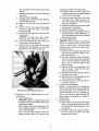
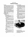
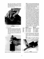
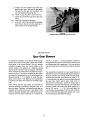
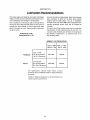
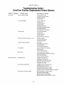
Price $5.00
DUROFLOW@
D-9-620
1st Edition
BO11O
Supersedes
SERIES
4500
BLOWERS
SERVICE MANUAL
#
COOPER
Gardner-Denver
Industrial Machine~
DUROFLOW.
45 Series Blowers
Table of Contents
Section
One:
Introduction
. . . . . . . . . . . . . . . . . . . . . . . . . . . . . . . . . . . . . . . . . . . . . . . . . . . . ...2
Section
Two:
Suggested
Section
Three:
Teardown
Section
Four:
Policy Replacement
Items
Section
Five:
Major Parts Cleanup
Procedures..
Section
Six:
Major Parts Inspection
Section
Seven:
Assembly
Procedure
Section
Eight:
SpurGear
Blowers
Section
Nine:
Operating
Limitations
Section
Ten:
Lubrication
Section
Eleven:
Parts Lists, Sectional
Section
Twelve:
Troubleshooting
Section
Thirteen:
Warranty
Equipment
Procedure
and Supplies
for a Major Overhaul
. . . . . . . . . . . . . . ...3
. . . . . . . . . . . . . . . . . . . . . . . . . . . . . . . . . . . . . . . . . . . . . ...5
. . . . . . . . . . . . . . . . . . . . . . . . . . . . . . . . . . . . . . . . . ..9
. . . . . . . . . . . . . . . . . . . . . . . . . . . . . . . . . ...9
Procedures
. . . . . . . . . . . . . . . . . . . . . . . . . . . . . . . . ...10
. . . . . . . . . . . . . . . . . . . . . . . . . . . . . . . . . . . . . . . . . . . . ...11
. . . . . . . . . . . . . . . . . . . . . . . . . . . . . . . . . . . . . . . . . . . . . . ...18
. . . . . . . . . . . . . . . . . . . . . . . . . . . . . . . . . . . . . . . . . . . ...19
Recommendations.
. . . . . . . . . . . . . . . . . . . . . . . . . . . . . . . . . . ...20
and Exploded
Views . . . . . . . . . . . . . . . . . . . . . . . . . . ...21
. . . . . . . . . . . . . . . . . . . . . . . . . . . . . . . . . . . . . . . . . . . . . . . ...23
Information
. . . . . . . . . . . . . . . . . . . . . . . . . . . . . . . . . . . . . . . . . . . ...25
SECTION
ONE
Introduction
and bottom
This manual was prepared as a guide for the person involved in the maintenance or overhaul of DuroFlow@ 45
Series Blowers
utilizing
splined
gears. There are two versions,
rotor shafts and timing
one of which
uses spur
gears and the other, helical gears.
The helical
gear version
In the horizontal-right
is mounted
The VT and HL configurations
are identical
the position
is the latest in the evolution
of the unit.
configuration,
the drive rotor
of the idler rotor.
of the oil breather
(HR)
to the right
except
and the oil filler
for
plug
and a change in the mounting
plate in the HL. Likewise, the VB and the HR configurations
correspond
to
of
DuroFlow blower technology.
It differs from its predecessor, the spur gear version, only in the gear tooth
each other with the same differences
configuration
The VT-HL differs from the VB-HR in having a different oil flinger on the drive end which is mounted on
the drive shaft in the VB-HR version rather than on
and the addition
of a Belleville
spring
behind one timing gear. On the helical gear blower,
rotor timing is accomplished
by varying the position of
a lock nut moving one timing gear axially
pressure of the Belleville
spring washer.
longitudinal
movement
the idler gear changes
tween the two rotors.
the angular
the proper
rotors.
This
gear
angular
flinger is more deeply dished
in the VB-HR versions.
to
be-
Since the VT version
various configurations,
In the spur gear version,
by selective assembly.
matched to a particular
relationship
rotor timing
is accomplished
manual
is concerned
which
is
version,
between
primarily
currently
the
two
end fiinger
is the most common
of the
the illustrations
and the tear-
should keep in mind
preceding paragraphs.
In addition,
with the helical
in production.
Section Eight covers the differences
in teardown
reassembly procedure for the spur gear version.
than thegear
down and reassembly procedures
in this manual refer
to the VT configuration.
The person
involved
in
overhauling
one of the other versions of the blower
A particular
set of gears is
set of rotors in order to achieve
relationship
HL.
the idler shaft as in the VT-HL. Both oil flingers are
identical in the VT-HL version, whereas the drive end
against the
This slight
of the drive gear in relation
as the VTand
versions,
if
the
overhauling
it is advisable
differences
either
noted
the
to use a holding
HL
in the
or
HR
fixture
to
secure the blower to the workbench.
This can be
obtained from DuroFlow or it can be fabricated
as in
and
Fig. 4.
Each of the four sizes of 45 Series
configurations
designated
blowers
by the position
It is suggested
that the appropriate
sections of this
manual be read and fully comprehended
before any
has four
of the drive
specific service operation
is attempted.
Further, the
importance
of a clean
and adequately
outfitted
workshop cannot be overemphasized.
The success of
shaft as viewed from the drive end. The most common
configuration,
designated
vertical-top
(VT), has the
drive rotor above the idler rotor and the airbox inlet
and discharge ducts are at the sides. In the verticalbottom (VB) configuration,
the drive rotor is mounted
below the idler rotor. In the horizontal-left
(H L)configuration, the drive rotor is to the left of the idler rotor
and the airbox
inlet and discharge
any major
recognition
Blowers
modifications
service
effort
depends
upon
fact that virtually
every part
contained
in the assembly
is highly
precise,
and
hence, is vulnerable
to the damaging effects of dirt,
moisture and rough handling.
ducts are at the top
IMPORTANT
In mid-1981,
blower
of the
NOTICE
to the 45 Series end plates were made that are not shown in the text of this manual.
now require only one conventional
breather
cap. This difference
When properly mounted, the air breather ports on modified
longer require breather caps. If these vent ports are threaded,
will not affect service procedures.
blowers are always facing downward,
and no
a breather vent will be inserted. DO NOT PLUG
OR OBSTRUCT THESE AIR VENT PASSAGEWAYS!!
The oil sump breathing
is now accomplished
oil fill hole, and the blowers’
only breather
through
the oil fill port. A hexagonal
cap is placed
2
in this bushing
bushing
is inserted
to vent the oil sump.
into the
SECTION
TWO
Suggested Equipment and Supplies for a Major Overhaul
A. Sturdy 3’ x 6’ workbench,
equipped
width, turret type machinist’s
vise.
B. 10 ton,
2-jaw,
5-1 /2” reach puller,
with a 5“ jaw
such as Snap-
On CG-270.
c. Wrenches
and PI iers.
1. 12“ adjustable
(“Crescent”
2. 9/16“ six-or twelve-point
bination.
type).
box/open
end com-
3. 3/8’ orl /2” square drive socket tools.
a. Ratchet handle.
b.
3“ to 6’ extension
c.
d.
9/16’ six-or twelve-point
socket.
Torque wrench, 1 ft-lb graduations
to 50 ftIb [7 mkg], such as Snap-On Nos. TE-50F or
STEEL
bar.
TE-51 F Torqometers.
I
4. 3/4” square drive socket tools.
a. Ratchet or sliding tee handle.
b.
c.
1-13/16’ six-or twelve-point
socket.
Torque wrench, 5 ft-lb graduations
to 350
ft-lb [50 mkg], such as Snap-On No. TE-352
Torqometer.
Q
~
1
L
———=
- COLD DRAWN
SEAMLESS
TUBING
2“
I
~;
c!
I
!
~
i’–
I
I
I
zWELD
‘~
I
J
J
&2.82”&
FIGURE 3
OIL SEAL INSTALLATION TOOL
O. D, 0.180 WALL
1/2” THICK MILD
PLATE
r—2“-7sTEEL
J
252,,
MATERIAL
3“
WELD
——.
Iy ‘\
/:’
T
5. Large internal snap ring pliers,
Tru-Arc No. S-6700.
such as Waldes
D. Hammers.
1. 24 ounce ball or cross peen.
2. 3 pound plastic faced or rawhide
mallet.
E. Chisels and punches.
1. 5/8” edge width flat chisel, blunted.
2. 5/16” shank diameter pin punch.
3. 118” point center punch.
F. Cleaning and deburring tools and supplies.
solvent,
1. Decreasing tank of chlorinated
I
I
I
,1
Ld
I
I _
1.64”
FIGURE 2
BEARING SLEEVE INSTALLATION TOOL
such as
perch lorethylene.
2. 12 clean shop rags.
3. Stiff, natural bristle scrub brush.
4. Wire wheel or brush.
5. 1-1 / 2“ edge width gasket scraper.
6. 8“ half round file, smooth or second cut.
7. Assorted
silicone
carbide or aluminum
abrasive paper, in 240, 320 and 400 grits.
G. Measuring
oxide
instruments.
1. Micrometer
caliper,
O“ to
0.001” [0 to 25 mm graduated
1“,
graduated
in 0.01 mm].
in
2. Depth micrometer,
1“ to 2“, graduated
[25 to 50 mm graduated in 0.01 mm].
3. Dial test
graduated
in 0.001”
1.
with
magnetic
clamp
base holder.
Service Specs CC and SE (See
Recommendations,
Sec. Ten).
2. 1 pound fresh assembly
lubricant,
molybdenum
disulfide grease.
to A.P. I.
such
block
as
appropriately
plate
to work
approximately
Special
tools and fixtures
3. Blower
NOTE:
zontal
chased
3“ x 6“ x 1 /2” to
tool (Figure
blowers.
from
If preferred,
DuroFlow
3).
this
can be pur-
(See Item 40, Section
tool (Figure
5).
I
I
7
3“
WELD
MODE L I
4504
I
- HOT ROLLED
A“
1.75
I
STEEL
B“
I
c“
Z75
I
6.25
I
,,
1
.1
,,
1
E
HOLDING
FIGURE 4
FIXTURE FOR 4500 SERIES BLOWER
to
bench.
holding fixture (Figure 4).
Holding fixture is needed only for hori-
Eleven).
4. Bearing installation
MATERIAL
x
(see sketches).
tool (Figure’2).
1. Rotor sleeve installation
2. Oil seal installation
Lubrication
sized
mounting
1-1 /2”
4. Awl.
J.
conforming
approximately
C-clamps
blower
3. Wooden
1“ thick.
4. 12“ x 1 /2” feeler stock, 0.002” to 0.015“ in
0.001” increments,
[0.04 to 0.40 mm], 2 strips
of each, such as Starrett Series 667.
H. Lubricants
and compounds.
1. 2 quarts fresh motor oil,
items.
blocks,
3-1/2’’ xlo’.
2. Two sturdy
indicator
(lever contact
arm type),
in 0.0005” or 0.001” [0.01 or 0.02
mm], and equipped
Miscellaneous
1. 3 wooden
.——
‘2A<
FIGURE 5
BEARING INSTALLATION TOOL
SECTION
THREE
Teardown Procedure
A. Preparation.
Before beginning
the teardown sequence,
the oil
should be drained from the unit. It is also suggested that the usual accumulation
of sludgy or
encrusted
material be removed from the exterior.
This can best be accomplished
by scouring with a
stiff bristle brush and soapy water, followed
by a
pressure rinse with water. An acceptable
alternative is steam cleaning,
if the equipment
is available. Because all salvable parts are made of cast
iron (or other ferrous alloy), virtually
any heavy
duty,
chemical
cleaning
agents—EXCEPT
those
which are ACIDIC—are
acceptable.
It should be
noted, however, that when water (or steam) is used
in the cleaning
process, the unit must be disassembled
pressed
faces.
immediately,
air to prevent
and blown dry with
rusting of machined
B. Teardown sequence.
NOTE: Numbers in parentheses
numbers
drawings
(
of the
unit
into
FIGURE 7
REMOVING BREATHER CAPS FROM GEAR END PLATE
) refer to key
in sectional
and exploded
on pages 22 and 23.
1. Separation
comsur-
basic
assembly
NOTE
subassem-
blies.
a.
All screw
standard
Securely fasten the unit to the workbench,
gear end facing out, using the mounting
or
holding fixture and C-clamps (see Fig. 6).
right-hand
on the blower
Remove the 2 breather caps from
end plate (7) (see Fig. 7).
c.
Remove eight pipe plugs.
Remove the 14 thru-bolts
d.
e.
are
threads.
b.
screws
the gear
(4) and
2 cap
(5) from the gear end cover (l).
Remove the gear cover (1) from the gear end
plate (7).
NOTE: The gasket
end
BLOWER SECURED
threads
plate
seam
used to seal the cover/
tends
to bond
tightly
to
FIGURE 8
FOUR CAPSCREWS WITH SPACERS BEING TEMPORARILY REPLACED IN
GEAR END PLATE
FIGURE 6
TO WORK STAND WITH “C” CLAMPS
5
both surfaces.
After bolt and screw
moval, it. is usually necessary to drive
the gear cover using
and blunted chisel.
f.
h.
reoff
gears appear to be reusable, it
to make index marks on the
gears to facilitate
the ball peen hammer
rotor
timing
upon
reas-
sembly. This can best be done by making
small punch marks on the ends of meshing
gear teeth with a pin punch and hammer
Temporarily
replace four of the cap screws
(4), two in each housing half, to retain the
(see Fig. 10).
gear end plate (7) during subsequent
operations.
NOTE: Each cap screw must be bushed
with a spacer to prevent bottoming
in the
9.
If the timing
is advisable
absence of the gear cover (see Fig. 8).
If the timing gears appear to be undamaged,
it is advisable to check the gear backlash
before removing gears to determine
they can be reused (see Fig. 9).
whether
(1) Mount
magnetic
base dial indicator
on
gear end plate with arm extending
toward drive gear.
(2) Lock idler rotor stationary by wedging a
feeler gage between idler rotor and end
plate.
(3) Place the tip of the indicator arm at approximately
the center of the contact
surface on a tooth of the drive gear.
(4) Rock the drive gear by hand and read the
total movement to the nearest .0005 in.
[.012 mm].
(5) Rotate the idler rotor 90°
measurement
three times.
and
(6) Permissible
is .0025 to
gear
backlash
FIGURE 10
INDEX MARKS ON ENDS OF GEAR TEETH
i.
repeat
.0055 in. [.064 to .141 mm].
NOTE: If backlash is outside specified
limits at this point, it does not neces-
j.
Place wood block between idler rotor lobe
and edge of inlet-discharge
opening to prevent rotor from turning.
Loosen but do not
remove the flexlock
nut from each rotor
shaft.
Move to drive
end
of blower.
Locate
the
tang of the spider washer (21) which was
bent into slot of lock nut (22). Bend the tang
out of the lock nut slot using pin punch and
hammer (see Fig. 11).
sarily mean gears are unusable because
the excessive play could be caused by
worn bearings.
However, if backlash is
within limits and there is no apparent
damage,
the gears may definitely
be
k.
Chock
blunted
reused.
FIGURE 9
CHECKING TIMING GEAR BACKLASH WITH DIAL INDICATOR
6
drive
rotor
flat chisel
with
wood
and hammer,
block.
Using
loosen lock
1.
nut (see Fig. 12). Use caution
age rotor shaft with chisel.
Remove lock nut and spider
discard
not to damwasher
r.
and
both as they will not be reused.
Remove the drive end plate from the remainder of the assembly
using soft faced
mallet to loosen end plate from dowel pins
in housing
halves (see Fig. 14).
CAUTION:
The
about 40 pounds.
drive end plate weighs
Use care not to drop it.
FIGURE 12
USING BLUNTED FLAT CHISEL AND BALL PEEN HAMMER TO LOOSEN
LOCK NUT
m
n.
Remove
washers
s.
washer assemblies
(5) from the drive end
cover (30).
Remove the drive end cover. It may be
necessary
to use blunted
flat chisel and
hammer to loosen cover from end plate.
o.
Remove bearing
(see Fig. 13).
P.
Chock idler rotor with wood block.
flexlock
nut (27) from drive end
Remove
of idler
shaft.
Remove oil flinger (29) and clamp
(28) from idler rotor shaft.
washer
q.
FIGURE 14
USING SOFT FACED MALLET TO LOOSEN DRIVE END PLATE
the 14 cap screws (18), 14 lock
(6), and two cap screw and lock
t.
Remove the flexlock nut (44) from the gear
end of the drive rotor shaft.
Remove the timing gear from the drive rotor
using the gear puller (see Fig. 15). Make
sure oil flinger (29) is turned so as not to
interfere with gear being removed from the
spacer (20) from drive shaft
drive shaft.
FIGURE 15
USING PULLER TO REMOVE TIMING GEAR
u.
v.
w
FIGURE 13
REMOVING BEARING SPACER FROM DRIVE SHAFT
7
Remove
the Belleville
spring
(48) and dis-
card as it will not be reused.
Separate the drive rotor from the gear end
plate (see Fig. 16).
Remove the two cap screws and spacers
holding the upper housing half (12) to the
gear end plate and remove the upper
ing half.
x.
y.
z.
aa.
bb.
cc.
dd .
ee.
Remove the flexlock nut (44) from
rotor shaft.
Remove the oil flinger (29).
replaced as a matter of service policy.
(1) Securely fasten the rotor in the vise,
using 2 wood blocks to prevent marring
of the contoured surfaces.
hous-
the idler
(2) Remove the seal ring (13) from the drive
end sleeve (14), using the awl to pry
apart the interlock,
and then break the
ring from underneath.
Use gear puller to remove the idler gear (42)
from the idler rotor (32).
Remove the idler rotor from the gear end
plate.
Remove
holding
the two cap screws and spacers
the gear end plate to the lower
housing
half (39).
Remove the gear end plate
housing half.
from
(3) Remove the seal ring (13) from the gear
end sleeve (11), as in Step 2.
(4) Remove shims (15) from rotors.
(5) Only as required in accordance with the
guidelines
given under PREFACE,
remove the sleeve(s) from the rotor shaft(s)
the lower
CAUTION:
The gear end plate
weighs
about 35 pounds. Use care not to drop it.
Loosen the C-clamps and invert the lower
housing half on the workbench.
Remove the four cap screws (37) and lock
washers
(38), and
separate
the
plate (40) from the lower housing
using the gear puller.
b.
mounting
End plate subassembly.
PREFACE:
Since all seals and bearings
should be replaced during overhaul as a
matter of service policy,
both end plate
subassemblies
half.
must
be completely
disas-
sembled internally.
(1) Remove the 2 retaining rings (26) from
their respective bearing sockets, using
the snap ring pliers.
(2) Invert the end plate on the work bench,
and set on 2 oak blocks,
3-1 /2” clearance
between
so as to provide
the plate and
bench, and to clear the edges of the
bearing sockets.
(3) Remove the drive rotor bearing (9) or(l 7)
from its socket,
using the ball peen
hammer and pin punch.
(4) Remove the drive rotor oil seal (10) from
its socket, as in Step 3.
(5) Remove the idler rotor bearing (9) or(17)
from its socket, as in Step 3.
(6) Remove the idler rotor oil seal (10) from
its socket, as Step 3.
c.
ponent
a.
of
the
subassemblies
into
com-
parts.
shou Id always
Rotor subassembly.
PREFACE:
Except
in unusual
end plugs in each rotor casting
removed or replaced.
Rotor
sleeves
need only
cases,
the 4
d.
need not be
be removed
should
always
be
removed
be replaced
service policy.
Drive end cover.
(1) Place cover on two wood
as a matter
blocks
of
gasket
side up. With hammer and punch drive
out the seal (25). Discard seal as it will
be replaced.
there is no reason to remove
(2) Normally,
the two dowel
pins (34) which
are
pressed into the cover.
from
their respective
shafts for the purpose of
rotor or sleeve salvage.
The 2 iron seal rings carried in the rotor
sleeves
pins
(34) and 2 ferrules (35) in each housing half
end surface need not be removed
or replaced. However, the 2 “O” rings (36) carried on the ferrules of each housing
half
FIGURE 16
REMOVING DRIVE ROTOR FROM GEAR END PLATE
2. Separation
Housing half subassembly.
Except in unusual cases, the 4 dowel
and
8
SECTION
FOUR
Policy Replacement Items
It is suggested
that the following
parts be replaced
each time the 45 Series blower is disassembled
regardless
of apparent
merely reflects sound
of these parts cannot
or measured
service policy
be justified
condition.
This
in that the reuse
savings when possible consequences
are considered.
It is not necessary to order these parts individually,
as
DuroFlow offers a factory service parts kit for the 45
Series, splined
shaft blower.
on the basis of cost
Description
Qty. Per Unit
Qty. Per Unit
Item No.
Roller Bearing
2
22
Lock Nut
1
10
Oil Seal
25
13
Seal Ring
4
4
Oil Seal
Gasket
1
2
15
Shim .002—.003—
0 Ring
4
17
.005—.007—.01
Ball Bearing
21
Lock Washer
Item No.
Description
9
31
36
46
As
O” Required
2
Gasket
Belleville
48
2
1
Spring
1
SECTION
FIVE
Major Parts Cleanup Procedures
A. Rotors.
1. Dip in decreasing
tank agitating
and brushing
to remove grease and oil.
2. Sandblast or wirebrush as necessary to remove
scale from rotor lobes. If sandblasting,
mask
bearing sleeves, bearing spacers, and shafts
with rubber hose or tape to prevent erosion.
3. Lightly wet polish the bearing sleeves, bearing
spacers,
and rotor shafts
with crocus
cloth.
4. Any burrs on rotor or shaft should be removed
with a file.
tank and blow dry with
5. Dip again in decreasing
compressed
air.
and reused im6. If rotor is not to be inspected
mediately,
dip in oil or rust preventative
solution and seal in a clean plastic bag for storage.
solution
age.
and seal in clean plastic
C. Housing halves.
1. Dip in decreasing tank agitating
to remove grease and oil.
bag for stor-
and brushing
2. Sandblast or wirebrush as necessary to remove
scale.
3. Wet polish the machined concave surface with
240 grit abrasive paper.
4. File burrs on machined surfaces.
5. Dip in decreasing
tank and blow dry with
com-
pressed air. Use particular
care to insure that
all foreign matter is purged from oil passages.
6. If housing is not to be inspected
and reused
immediately,
dip in oil or rust preventative
solution
and
seal
in
clean
plastic
bag
for
storage.
B. End plates.
1. Dip in decreasing
tank agitating
and brushing
to remove grease and oil.
2. Sandblast or wirebrush as necessary to remove
scale.
If sandblasting,
place plugs
in seal ring
bores to prevent erosion during blasting.
3. Lightly wet polish the seal ring bores with 400
grit abrasive paper.
4. Remove burrs with file.
tank and blow dry with com5. Dip in decreasing
pressed air.
6. If end plate
immediately,
is not to be inspected
dip in oil or rust
and reused
preventative
D. Timing gears.
1. Dip in decreasing tank to remove grease and oil.
2. Wirebrush as necessary to remove scale.
3. Remove nicks and burrs with file.
4. Dip in decreasing
tank and blow dry with compressed air.
5. If gears are not to be inspected and reused immediately,
dip in oil or rust preventative
solution and seal in clean plastic
E. Covers.
1. Dip in decreasing
bag for storage.
tank agitating
to remove grease and oil.
and brushing
F. Mounting plate, flingers, and external hardware.
1. Dip in decreasing
tank to remove grease and
2. Scrape gasket surface to remove any remaining
pieces of gasket.
3. File any burrs on gasket surface.
4. Dip in decreasing
tank and blow dry with compressed air.
2.
oil.
File burrs from mounting
surfaces
of mounting
plate.
5. If covers are not to be inspected and reused immediately,
dip in oil or rust preventative
solution and seal in clean plastic bag.
3.
SECTION
If parts are not to be reused immediately,
in clean plastic bag.
store
SIX
Major Parts Inspection Procedures
A. Rotors.
The rotors
degeneration
occurred.
cylindrical
are usually
salvable
of the contoured
or end surfaces
checked
has
be checked
for uniformity
with end plates, housings,
rotor lobe length and width
contact
3.982-3.986
4512
5.978-5.982
mm]
7.372-7.374
in.
mm]
7.372-7.374
11.971-11.977
7.372-7.374
in.
[304.07 -304.22
mm]
B. End plates.
The end plates are usually
box and seal ring
mm]
smoothness.
bent, but can be straightened
so that the mounting
holes line up, it may be reused. External hardware
mm]
can be reused
if the planar air
appear
undam-
G. Flingers.
Usually salvageable,
disturbance
is allowable.
If seizure of the rotor
group had occurred
during
operation,
the end
plates should be checked for cracks.
damage around
be replaced.
halves.
halves
are usually
salvable
the threads
are good
and
shaft which should always be replaced as a matter
of service policy. The oil gage plug and breather
filters should also be replaced.
usually found without more extensive damage to
surrounding
areas. Ring bore condition,
however,
is critical.
No visible evidence of surface finish
housing
provided
the heads of screws and plugs are not too severely
deformed.
Exceptions
to this are the spider type
lock washer and external
lock nut on the drive
aged. As with the rotors, moderate localized gouging of the air box surface is allowable
but is not
The
The seal bore of
be examined
for
F. Mounting plate and external hardware.
The mounting
plate is nearly always salvable provided it is not cracked or severely bent. If it is
mm]
in.
[187.25 -187.30
bore surfaces
there are no wearing surfaces.
the drive end cover should
in.
[187.25 -187.30
salvable
mm]
in.
[187.25 -187.30
spherical
E. Covers.
The gear end and drive end covers are nearly always salvable provided there are no cracks since
in.
[187.25 -187.30
salvable if the meshof profile degenera-
tooth wear has gone beyond acceptable
limits,
it
is necessary to check the backlash when the pump
is reassembled.
for advice):
Width
8.976-8.982
in.
[228.00 -228.14 mm]
c. Housing
be
during
can be tolerated.
This produces a tooth contact
pattern
that is characteristically
elliptical
and
somewhat
more polished
than that of the surrounding tooth surface. To determine whether gear
and smoothness
7.372-7.374
in.
[151.84 -151.94
4509
As
crown so that small errors in axial rotor alignment
or with each other, the
should be measured.
factory
[101.14 -101.24
4506
had occurred
tion. The gear teeth are cut with a slight
The following table gives lengths and widths for the
various 45 series models (If specifications
outside
4504
if seizure
halves should
operation.
and should be free of burrs, eruptions,
and other
irregularities.
If there is evidence of rotor contact
these limits,
Models Length
for cracks
appear undamaged.
the housing
D. Timing gears.
The timing gears are usually
ing teeth show no evidence
Occasionally,
a hard object accidentally
passes
through the blower causing localized gouging of
the lobes. This is not necessarily
grounds for immediate rejection unless the gouging takes place
on the tip sealing
vanes. Rotor end surfaces
should
air box surfaces
with the end plates,
if no significant
if the
10
but if any cracks
the center
hole exists
or surface
they should
SECTION
SEVEN
Assembly Procedure
A.
b.
Preparation.
All
metallic
spirits
ings
parts
should
to remove
from
gested
residual
deburring
that
operation
all
also
eliminate
any
traces
It
to be used
undergo
solvent
in clean
operations.
tools
yet another
Following
be rinsed
immersed
dirt
or fil-
is
also
sug-
a solvent
oil seal installation
wash,
so
as
bal I peen hammer
to drive the seal
securely onto its seat.
(2) Install another presoaked oi I seal in the
to
wash, the parts and tools should
drive socket
(1) above.
air.
rotor shaft seals (1O) and (25) shou Id be
blower fora period of at least two (2) hours prior to
installation
in the end plates. This will allow the
to
as in Step
bearing
hammer
prevent
instal Iation tool and ball
to drive the bearing tightly
peen
onto
elastomers
to absorb
accelerated
early wear.
its seat.
sequence.
NOTE: Install roller bearings in gearend
plate and ball bearings in drive end plate
B. Reassembly
oil
of the end plate,
(3) Install the idler bearing (9) or(17) in the
idler socket of the end plate using the
in fresh motor oil of the type used in the
sufficient
oil seal (10) on the
tool and instal I the
seal in the id Ier socket of one end plate
(7) or (33), metal side down, using the
reassembly
source of contain i nation.
be blown dry with clean compressed
The elastic
of
in the
End plate subassembly.
(1)Place one presoaked
mineral
1. Rebuilding
component
parts into basic subassemblies.
a. Rotor subassembly.
If the sleeves were removed as described in
(drive end plate is thicker).
(4) Install the drive bearing (9) or (17) in the
drive socket of the end plate, as in Step
Section Ill, proceed as follows:
(1) Lightly coat the gear end rotor shaft and
the bearing sleeve (11 ) bore with assem-
(3) above.
(5) Install the 2 retaining
rings (26) in their
respective
bearing
sockets,
bevelled
bly lubricant.
(2) Install the bearing
sleeve
side out, using the snap pliers (see Fig.
17). Make certain the snap rings are
properly seated in their grooves.
(11) on the
gear end rotor shaft, using the
sleeve instal Iation tool and ball
hammer to drive the sleeve tightly
rotor
peen
onto
its seat.
NOTE: The face of the seal ring end of
the sleeve is notched out in two places
to provide clearance for tips of the mating rotor lobes. Therefore,
the sleeve
must be installed in such a position that
the valley sections of its rotor are both
totally encompassed
by a notch on both
sides.
(3) Lightly coat the drive end rotor shaft
and the bearing spacer (14) bore with
assembly lubricant.
(4) Install the bearing
spacer
(14) on the
drive end rotor shaft,
as in Step (2)
above.
If sleeves were not removed, or after rein-
FIGURE 17
INSTALLING RETAINING RING
stalling them:
(5) Coat the seal ring groove with assembly
lubricant. Install and couple the seal ring
(13) on the bearing
c.
sleeve (1 1).
(6) Install and couple the seal ring (13) on
the bearing spacer (14), as in Step (5)
above.
Housing half subassembly.
Assuming
that the 4 dowel pins (34) and 2
ferrules (35) were not removed, install the 2
“O” rings (36) on the ferrules
d.
11
Drive end cover (30).
(35).
Invert
cover
and
place
on
wood
blocks
NOTE: The lower housing half differs from
the upper housing half in that the lower half
has one through hole from end to end while
gasket side down. Wipe excess oil from O.D.
of presoaked seal (25). Place seal in its bore
with metal face up and
mallet to seat securely.
tap
with
b.
the upper half has two through holes.
Invert assembly and secure mounting
c.
to workbench with “C” clamps.
The clearance between the air box surface
plastic
plate
of the drive end plate and the drive end of
the rotors is controlled
by placing shims of
the required number and thickness
on the
drive end of each rotor between the bearing
spacer and the inner race of the ball bearing. The procedure for determining
the shim
thickness required for each shaft is as follows. Using depth micrometer,
measure the
distance from the planar air box surface to
the inner race of the double row ball bearing
reading to the nearest .0005 in. (see Fig.
17A). For the corresponding
shaft, measure
from the outer end of the bearing
spacer to
end of the rotor lobe reading to the nearest
.0005 in. (see Fig. 17B). The first measurement minus the second measurement
plus
the appropriate
drive end clearance specified in the table below is the total shim
thickness
required.
(If specifications
are
outside these limits, contact factory.)
FIGURE 17A
MEASURING FROM AIRBOX SURFACE TO INNER RACE OF
BALL BEARING
Drive End
2.
Final
a.
assembly.
Model
Place
lower
housing
bench
with
cylindrical
Place
mounting
align
holes,
screws
Torque
plate
half
assembly
(39)
on
housing
Gear End
Minimum Clearance
Clearance
on
air boxsurfacedown.
(40)
Minimum
half,
4504
.005 in. [.127 mm]
.006 in. [.152 mm]
4506
.005 in. [.127 mm]
.007 in. [.178 mm]
.010 in. [.254 mm]
.007 in. [.178 mm]
.016 in. [.406 mm]
4509
4512
secure with
four cap
(37) and four lock washers
(38).
cap screws to 50 to 60 ft-lb [7.0 to
and
d.
8.3 mkg].
.014 in. [.356 mm]
Assemble
the required shim stacks, reading the micrometer
caliper to the nearest
0.0005”
across
the total
lamination
of
shims to be used, so as to reduce additive
FIGURE 17B
MEASURING FROM END OF BEARING SPACER TO END OF ROTOR LOBE
error.
NOTE:
Always
shims
necessary
use the
to
least
obtain
number
the
FIGURE 18
ASSEMBLING SHIMS TO DRIVE END OF DRIVE ROTOR SHAFT
12
of
required
stack
e.
f.
thickness,
as this
reduces
the
ap-
j.
Install
the upper
housing
half to the drive
parent loss later produced by retaining
nut
compression.
Install the assembled
shim stacks (15) on
end plate. Ferrule with “O” ring must mate
with counterbored
hole in end plate. Secure
with two cap screws (18) using a 1 /2-13 nut
their respective
Fig. 18).
spacer under the head of each cap screw
(see Fig. 21). Torque cap screws to approximately 30 ft-lb [3.9 mkg].
drive end rotor
shafts
(see
Install the drive end plate to the lower
housing half with two cap screws (18) using
a 1 /2-13 nut spacer
under the head of each
cap screw (see Fig. 19).
Torque cap screws to approximately
30 ft-lb
[3.9 mkg].
FIGURE 21
TWO CAPSCREWS WITH SPACERS USED TO TEMPORARILY FASTEN
UPPER HOUSING HALF TO DRIVE END PLATE
k.
FIGURE 19
TWO CAPSCREWS WITH SPACERS USED TO TEMPORARILY FASTEN
DRIVE END PLATE TO LOWER HOUSING HALF.
g.
Brush the bearing
h.
of both rotors with assembly lubricant.
Install the idler rotor to the drive end plate.
spacers
i.
Use extreme care in starting the seal ring in
the bore as the ring can easily be broken.
Assemble
the drive rotor to the end plate
Brush the bearing
of both rotors
stall
gear
sleeves on the gear ends
with
end
assembly
plate
using
lubricant.
care
in-
to avoid
damage to the seal rings during assembly.
Secure end plate to housings using six cap
screws with 1 /2-13 nut spacers (see Fig.
22). Torque screws to approximately
30 ft-lb
on the drive ends
[3.9 mkg].
1.
Lubricate
threads
with assembly
on drive end of each shaft
lubricant.
FIGURE 22
SIX CAPSCREWS WITH SPACERS USED TO TEMPORARILY FASTEN GEAR
END PLATE TO UPPER AND LOWER HOUSING HALVES
13
m. Assemble clamp washer (28) and oil flinger
(29) to drive end of idler shaft (see Fig. 23).
Be sure that oil flinger
cave side out.
is assembled
punch, tighten lock nut sufficiently
press shim stack (see Fig. 25).
con-
FIGURE 23
ASSEMBLING CLAMP WASHER AND OIL FLINGER TO DRIVE END OF
IDLER SHAFT
n.
Assemble
flexlock
nut
(27)
to
to com-
FIGURE 25
TIGHTENING LOCK NUT TO CHECK DRIVE END CLEARANCE
q.
drive
end of
between idler
Check
drive
end
plate
to
rotor
lobe
clear-
nut to
each rotor with feeler gages (see
Fig. 26). (Drive end clearance
for each
model is specified
in table following
Step
o.
300 ft-lb [42 mkg] (see Fig. 24).
Assemble bearing spacer (20) to drive end
c of Final Assembly procedure on page 12).
If clearance is not within specified limits for
P.
of drive shaft.
Assemble lock nut (22) to drive end of drive
each rotor, remove the drive end plate and
add or remove shims as necessary to adjust
shaft
clearance.
ance.
idler shaft.
rotor
lobe and
prevent
body.
Place wood
rotor
with
inlet
from
chamfer
Using
block
or discharge
turning.
facing
hammer
and
duct
Torque
toward
blunted
ance
to
pump
flat
r.
for
Reassemble
When
drive
end
temporarily
remove
taining
and recheck
clearance
the snap
clear-
is correct,
rings (26) re-
the drive end bearings.
CAUTION: Failure to remove these rings may
result in damage to the double-row ball bearings during
FIGURE 24
TIGHTENING LOCK NUTS WITH TORQUE WRENCH
installation
of the timing
FIGURE 26
CHECKING DRIVE END CLEARANCE WITH FEELER GAGE
14
gears.
s.
Brush the gear end splines
both shafts with assembly
semble
with
and threads of
lubricant.
As-
the idler gear (42) to the idler shaft
the
large
diameter
boss
toward
blower body. Use plastic or rawhide
to start idler gear onto shaft.
t.
Place oil finger
on idler shaft with con-
cave side in toward
u.
the
mallet
Lubricate
flexlock
idler shaft. Chock
gear.
nut (44) and install on
rotor with wood block to
prevent its turning. Tighten lock nut to seat
gear against bearing sleeve. Then back off
v.
lock nut enough to permit
f reel y.
Rotor timing procedure.
oil flinger
to turn
On the helical gear blower,
rotor timing
(rotor to rotor clearance) is adjusted by a
system
in which
drive rotor
rotational
is transferred
motion
FIGURE 28
ROTOR AND SPACER BLOCK POSITION FOR INDEXING GEARS
(AS VIEWED FROM GEAR END)
of the
to the idler rotor
rotor
by means of two meshed helical gears, each
splined to its respective
rotor shaft. The
shaft,
concave
side
out
toward
gear (see Fig. 27).
(3a) If gears are being reused, align the index
marks made on the gears during tear-
axial position of the idler gear is fixed as
the gear face butts against
the bearing
down.
Make sure that the wide
land in
sleeve and is held there by a lock nut. The
axial position of the drive gear is slightly
adjustable as the drive gear is clamped be-
the drive gear spline is aligned with the
missing tooth on the drive rotor shaft.
Start drive gear on rotor shaft using
tween
plastic
enough
a conical
spring
washer
spring) and a lock nut. Axial
the drive gear, accomplished
the
lock
nut
against
(Belleville
movement of
by tightening
spring
or rawhide
faced
mallet
far
to engage flexlock nut two turns
by hand.
(3b) If new gears are used, align rotors paral-
pressure,
changes the angular relationship
between
the two rotors
thereby
changing
their
timing.
(1) In order to time the rotors,
it is first
necessary
to start the gears on their
rotor shafts in proper relationship
to
each other.
(2) Place Belleville
Spring
(48) on the drive
FIGURE 27
POSITIONING BELLEVILLE SPRING AND DRIVE GEAR BEFORE
ASSEMBLING TO DRIVE ROTOR SHAFT
FIGURE 29
STARTING DRIVE GEAR ONTO SHAFT WITH SOFT FACED MALLET
15
approximately
15”
(l-1/2
w.
while
stationary.
meshing
it
teeth)
idler gear and rotor remain
Push drive gear onto shaft
with idler gear. Use mallet
clearances
should be checked
gages (see Fig. 31).
to move gear
The two drive end snap rings
porarily
(5)
removed
(26) tem-
on page 14 should
6A
A
cc
c
c
D
B
D
BCA
AB
aligned, check rotor-to-rotor
clearance at
arrows in Fig. 28. If clearance is greater
(6)
feeler
D
now
be replaced.
Drive gear onto shaft by turning flexlock
nut. When the inner faces of gears are
than .016” continue
turning
nut
.016” is obtained.
Rotors should
with
Qm
onto shaft far enough to engage flexlock
nut two turns by hand (see Fig. 29).
(4)
When correct rotor timing has been estabIished, the other interior rotor and air box
ADB
c
until
then
B
BA
D
c
DD
A
AB
turn freely.
If tightening
drive gear lock nut does not
free rotors, the gears have been improperly meshed. Remove drive gear, fit
~
FIGURE 31
POSITIONS OF ROTORS FOR CHECKING INTERNAL CLEARANCE
a new Belleville spring, and repeat gear
indexing procedure (Item 3b above).
(7)
Before making
torque idler
[42 mkg].
(8)
final timing
gear
lock
(1) Clearance between tip of one rotor lobe
and valley of other rotor (C-C and D-D)
adjustments,
nut to 300 ft-lb
should
When rotors turn freely,
it is still
neces-
the rotor
lobes
at position
Adjust
be
(2) Clearance between the rotor tips and the
housing halves should be a minimum of
.0040 in. [.102 mm].
It should
be
measured
at several places along the
length of each of the four rotor lobes.
(3) Gear end rotor to end plate clearance is
measured between the end of each rotor
so that clear-
of each
the rotors
to valley positions.
A-A
ance at A-A is equal to B-B within
+ .001 in. [.025 mm]. Clearance must be
checked on both sides
lobe near each end.
with
to each other. It should
checked several places along the length
of the rotor for each of the four lobe tip
and B-B to check clearance.
Adjust
clearance by tightening
flexlock nut on
drive rotor shaft. One-sixth of a turn of
the nut will change the clearance
by
.005 in. [.13 mm].
of .0040 in. [.102
is measured
perpendicular
sary to adjust rotor clearances
to be
equal on both sides. Refer to diagram in
Fig. 30. Use feeler gages placed between
be a minimum
mm]. This
lobe and the gear end plate.
rotor
The gear
end clearance for each model is specified in the table on page 12. If the gear
end clearance
is not within
limits,
re-
check the drive end clearance (refer back
to Item q.), as gear end and drive end
clearance
CAUTION:
rotor-to-air
are interdependent.
These
rotor-to-rotor
and
box clearances are extremely
critical.
Even though
the blower may
turn freely by hand when cold;
under
operating
conditions,
the parts expand,
and the rotors are subject to slight deflection.
If the clearances are not sufficient, the rotors may contact each other
or the housing with destructive
results.
-------- 3U
-I-ltiul’lt
If the
POSITIONS OF ROTORS FOR CHECKING TIMING
16
clearances
are
too
great,
the
blower
may
not
develop
the
airflow
that
is
required
to
pressure
or
perform
its
99.
semblies
function.
x.
Insert 14 cap screws
Check gear backlash
four
intervals
as described
in
places at 90°
the Teardown
the specified
further
with assembly.
limits,
(5) through
as-
holes in cover and end
plate. Torque all cap screws to 28 to 32 ft-lb
Sequence (Section Ill, Item B., 1., g.).
NOTE: If any of the four readings are not
within
(18) and lock washers
(6) and two cap screw and lock washer
hh.
[3.9 to 4.4 mkg].
Assemble lock washer
drive shaft with tangs
of shaft (see Fig. 33).
do not proceed
(21 ) to drive end of
outward
toward
end
If a new set of gears
does not solve the problem then consider
returning
the unit to DuroFlow
for credit
y.
towards a remanufactured
blower.
After correct gear backlash has been established,
remove the six cap screws and
z.
spacers used to tern porari Iy secure the gear
end plate to the housing halves.
Assemble gasket (31 ) to gear end cover(1).
Assemble
gasket and cover to gear end
plate with 14 cap screws (4), 14 lock wash-
aa.
ers (6) and 2 cap screw and lock washer
assemblies
(5). Torque all cap screws to 28
to 32 ft-lb [3.9 to 4.4 mkg] (see Fig. 32).
FIGURE 22
ASSEMBLING SPIDER WASHER AND LOCK NUT TO DRIVE SHAFT
ii.
Reassemble
lock nut (22) to drive shaft with
chamfer toward blower body. Tighten
nut securely with hammer and punch
Fig. 34).
NOTE:
formed
if blower rebuilding
is to be peron a regular basis, a special tool for
the drive
detailed
tool
lock
(see
rotor
drawing
is available
lock
nut
is suggested.
for the fabrication
from
DuroFlow
A
of this
upon
quest. if the special tool is used,
lock nut to 300 ft-lb [42 mkg].
re-
torque
FIGURE 32
ASSEMBLING GEAR END COVER AND GASKET TO END PLATE
Move back to d rive end of blower.
bb.
cc.
Remove lock nut (22) from drive rotor tem-
dd .
porarily y.
Remove 4 cap screws(18)
ee.
ff .
holding
drive end
plate to upper and lower housing halves.
Assemble gasket (31 ) to drive end cover (30).
Assemble
plate.
gasket
and
cover
to drive
FIGURE 34
TIGHTENING DRIVE SHAFT LOCK NUT SECURELY WITH BLUNTED
CHISEL AND BALL PEEN HAMMER
end
17
Choose
jj.
the
lock
washer
tang
that
best
lock nut (22). Bend
the tang into the lock nut to prevent lock
nut from backing off (see Fig. 35).
aligns
with
a slot
in the
kk.
Install
oil gage plug (43) in gear end cover.
II.
Install
two oil breather
mm.
nn.
caps (8) in gear end
cover.
Install the other eight pipe plugs.
If the unit is not to be installed immediately
cover the air inlet and outlet openings
prevent the entry of foreign material.
to
SECTION
EIGHT
Spur Gear Blowers
As
mentioned
utilized
tooth
spur
gears
(besides
the
in Section
tooth
timing
in the current
gears)
from
1, the
former
gears
rather
design.
the
Item B., l.,g.
helical
drive gear and idler gear in some way so that they can
be differentiated
upon reassembly.
This can be done
with the center punch and hammer or with an etching
model
change
to the
tool.
current model is the addition
of a Belleville
spring
washer behind the drive rotor timing gear. Therefore,
when overhauling
a blower with a reusable set of spur
gears and rotors,
it is optional
whether
The reassembly
procedure for a spur gear blower is
identical to that for the helical gear blower except for
the spur gears
are reused or replaced with a set of helical gears and
Belleville
spring.
If it is desired to reuse the spur
the gear assembly
type.
timing
with
the spur
gears
is controlled
and timing.
With
the spur gears,
assemble the idler gear as in Section Vll, Item B., 2.,
s. Assemble the drive gear to the drive shaft aligning
the gear idex marks which
were made prior to
removing the timing gears. Chock the rotors with a
gears, some steps in the teardown
and reassembly
procedures will differ from those for the helical gear
Rotor
to mark the
design
than
The only
former
and h.;
it is also necessary
blower
by
wood block and torque both flexlock nuts to 300 ft-lb
[42 mkg]. Check rotor timing with feeler gages as in
selective assembly
(matching
a particular
rotor to a
particular gear). Therefore, it is essential each gear be
replaced on the shaft from which it was taken. After
Section Vll, Item B., 2., v., (7). With spur gears the
rotor timing is notadjustable.
If the timing is not within
limits, remove the spur gears and replace with a new
checking the gear backlash and marking the ends of
the gear teeth for proper indexing
as in Section Ill,
set of helical
18
gears and Belleville
spring.
SECTION
NINE
Operating Limitations
DuroFlow
45 Series blowers
are designed
to be
operated at 4000 RPM maximum and no more than 2:1
pressure ratio. The table below gives characteristic
inlet airflow
speeds
and
and horsepower
pressures.
requirements
Attempting
to
blower at speeds and pressures
above the rated
maximum will cause premature bearing and seal wear
and will void the warranty.
CAUTION: Outlet temperatures
for various
operate
the
should
not exceed
350”F.
OPERATING CHARACTERISTICS
(Data based on standard air at inlet (14.7 psi @ 60”F)
SPEED (RPM)
2000
MODEL
4504
Psl
HP
2
165
2.5
145
130
120
5
225
205
8
9.5
11.5
185
175
162
12
15
110
CFM
3
6.5
10
12.5
150
15
18
HP
280
260
3.5
8
240
230
215
203
12
15
18.5
23
430
400
6
12.5
380
CFM
335
315
295
HP
CFM
HP
4.5
390
5.5
9
14
17.5
370
351
11
16.5
20.5
287
270
255
22
27
337
325
513
485
460
6.5
600
14.5
22.5
565
8
16.5
28
540
530
26
32.5
39
48
308
26
31.5
260
4
5
235
8
10
215
200
8
12
340
320
295
10
16
12
185
14.5
17.5
285
265
19
23
365
350
19
23.5
28.5
445
435
250
28
349
35
415
33.5
41
515
495
775
735
11.5
23
900
13.5
26
39
48
57
70
5
2
395
6
525
8
650
5
360
12.5
480
16
615
8
10
330
19
23.5
450
435
24
29.5
575
555
19
29
36
27
420
35
540
385
43
510
705
10
870
12
315
290
15
4512
HP
2
15
4509
CFM
5
8
10
4506
CFM
4000
3500
3000
2500
2
5
540
480
8
16
445
23
8
10
420
28
12
400
34
15
650
610
20
30
580
560
37
44
520
54
19
9.5
700
34
42
680
660
42
50
855
820
800
780
52
630
61
755
12
1040
14
1205
16.5
820
775
745
25
37
45
980
935
30
44
1150
1100
34
51
720
54
905
880
54
64
1065
1040
62
74
680
66
845
78
1010
90
SECTION
TEN
Lubrication Recommendations
The blower
gears and bearings
are splash
lubricated.
Oil level should
be checked
daily.
Wait three minutes
Proper oil level must be constantly
maintained
to prevent overheating
and damage to internal parts.
after shutdown
to allow oil to drain down before
reading level at sight glass. Top up if necessary
After
through
months
installation
of the blower,
add oil through
the oil
fill plug on top of the drive end plate. Fill only until oil
reaches the level midway in the oil gage plug sight
glass in the gear end cover. Approximate
oil fill plug. Every 500 hours of operation (or 6
whichever
occurs first) the oil should
be
changed.
oil capacities
Oil used in DuroFlow blowers must meet or exceed the
requirements
of SAE specifications
SE and CC. The
are given below.
viscosity
Vertical-30 oz. [0.9L]
Horizontal-56 oz. [1.7L]
used depends
upon ambient
and severity of application,
the following tabie;
AMBlENT
AIR TEMPERATURE
–65 F
to 40 F
–54 C
to
40°F to 110°F
40C
I
4C
to
43 C
I
I
l.Oto 1.7 P.R.
0 to 10 psig pressure
0 to 10 in. Hgvacuum
PRESSURE
1.7t02.0
For
applications
DuroFlow.
SAE 20
SAE 20W
SAE 40
P.R.
10 to 15 psig pressure
10 to 15 in. Hgvacuum
RATIO
SAE IOW
outside
Oils of different
these
limits,
consult
brands or types should
not
be mixed.
10W4O or 15W40 multigrade
ordinary
operating
conditions.
20
oil is recommended
for all
air temperature
i.e., pressure
ratio, as in
SECTION
ELEVEN
Parts Lists, Sectional and Exploded Views
A list of current part numbers is available upon written request from DuroFlow.
replacement
parts may be ordered by part number from the Parts List.
dbdb
Alternatively,
@d @@b@@@
Sectional View
DuroFlow 45 Series Blowers
VARIABLE
ITEM
NO.
12
23
NAME OF PART
Top Housing
1
PARTS LIST
4512
4509
4506
4504
135069
135729
135431
135720
135437
135720
141562
180928
180932
180931
180926
180930
24
Shaft Key
Drive Rotor
180929
32
Idler Rotor
180933
39
40
Mounting
46
Gasket
Bottom
180927
141534
141535
Housing
135070
135432
Plate
135405
135436
135438
135442
141541
135716
135717
135718
141539
21
Exploded View
DuroFlow 45 Series Blowers
(Consult
Mounted
Item
No.
1
2
3
4
5
6
7’
8*
9
10
11
12
13
14
15
16’
17
18
19
20
21
22
23
24
*
Name
of Part
Part
Number
Cover-GearEnd . . . . . . . . . . . . . . . . .
135075
Self TappingScrew . . . . . . . . . . . . . . . . 129309
NamePlate. . . . . . . . . . . . . . . . . . . . . ,,, 143606
Capscrew. . . . . . . . . . . . . . . . . . . . . . . . 134674
Capscrew&L.W.Assy.
132579
Lockwasher. . . . . . . . . . . . . . . . . . .
2917
EndPlate-GearEnd
.(137430) 180672
BreatherFilter..........,...,,,.
140887
Roller Bearing......,,,,,,...,..
138113
Oil Seal . . . . . . . . . . . . . . . . . . . . . . . . . . . 161200
BearingSleeve, . . . . . . . . . . . . . . . . .
138100
HousingHalf-Top
.,
,..
Variable
SealRing . . . . . . . . . . . . . . . . . . . . . . . . 139986
BearingSpacer, . . . . . . . . . . . . . . . . . . 134662
Shim . . . . . . . . . . . . . ...135726-7-8and 159076-7
PipePlug(l”)
. .(158285) 186545
Ball Bearing.........,,.,.,,,,,,
138116
Capscrew. . . . . . . . . . . . . . . . . . . . . . . . 134675
Oil Deflector.,,..............,,,
139466
BearingSpacer........,.....,..
134671
Lockwasher. . . . . . . . . . . . . . . . . . . .
138257
Locknut . . . . . . . . . . . . . . . . . . . . . . .
128040
Key . . . . . . . . . . . . . . . . . . . . . . . . . . .
Variable
Rotor-Drive., .,, ,,, . . . . . . . . . . . .
Variable
Note
-
Quantity
Item
Per Blower
No.
25
26
27
28
29..
1
4
1
14
4
28
(1) 1
(2) 1
2
4
2
1
4
2
As Required
(2)2
2
14
1
1
1
1
1
1
Part Number and/or quantity needed with old
style
30
31
32
33‘
34
35
36
37
38
39
40
41‘
42
43
44
45*
46
47
48
1-143095.
22
for Truck
Part
Quantity
Name of Part
Number
Per Blower
Oil Seal . . . . . . . . . . . . . . . . . . . . . . . ...
134870
1
4
125606
SnapRing.....................,,,
Flexlock Nut . . . . . . . . . . . . . . . . . . ,,,
124793
1
135766
1
ClampWasher, . . . . . . . . . . . . . . . . .
..
Finger. . . . . . . . . . . . . . . . . . . . . . .
See Below
Cover-DriveEnd. . . . . . . . . . . . . . . . .
1
135074
135715
Gasket . . . . . . . . . . . . . . . . . . . . . . . .
2
Variable
Rotor-idler, . . . . . . . . . . . . . . . . . . . .
EndPlate-DriveEnd.
.(137429) 180673
(1; 1
Dowel . . . . . . . . . . . . . . . . . . . . . . . . .
10
121880
119034
Ferrule . ., . ., . . . . . . . . . . . . . . . . .
4
4
119058
“O’’Ring. . . . . . . . . . . . . . . . . . . . . . . . .
CapScrew . . . . . . . . . . . . . . . . . . . . . .,, 100963
4
Lockwasher. . . . . . . . . . . . . . . . . . .
4
2675
HousingHalf-Bottom
.
...
1
Variable
Mounting Plate(Vertical)
1
Variable
PipePlug(318’’). .,, ,,, ,,, ,,, ,.. .
21360
(2) 2 or O
Gearldler L,H. . . . . . . . . . . . . . . . . . . .,, 181377
1
Oil GagePlug. . . . . . . . . . . . . . . . . . . . . 137799
1
FlexlockNut . . . . . . . . . . . . . . . . . .
2
124793
PipePlug(112’’), ,,, ,,, ,,, ,, . . . . .
(4) O or 2
9620
Gasket . . . . . . . . . . . . . . . . . . . . . . . . .,, Variable
2
GearDriveR.H.,,,....,......,,,
1
181378
Belleville Spring . . . . . . . . . . . . . . . . ,,, 181069
1
end plates are in parenthesis.
** Flingers - For V1/HL shaft configurations use 2-134652.
For VB/HR shaft configurations use 1-134652 and
DuroFlow
Blowers)
SECTION
TWELVE
Troubleshooting Guide—
DuroFlow Positive Displacement Rotary Blowers
Problem
or Complaint
Noisiness
Probable
Causes
Rotor-to-Rotor
Usual Reasons or Sources
- Rotors Out of Time
Contact
- Excessive Pressure
- Failed Bearing(s)
Ratio
- Failed Gears
Failing
Bearing(s)
- Faulty
Installation
- Nonspec
Oil
- Contaminated
Oil
- Insufficient
Oil
- Oversized
Belt Drive
- Improperly
Mounted
- Overtightened
- Misaligned
Failing
Direct Coupling
- Insufficient
Gears
- Nonspec
Sheave
Belts
Backlash
Oil
- Contaminated
Oil
- Insufficient
Oil
- Severe Torsional
Failing
Lubricated
Coupling
or Joint
- Nonspec
Grease
- Contaminated
- Insufficient
Loose Attached
Vibration
Grease
Grease
- Belt Guard
Hardware
- Pump Mounting
Bracket
- Frame Members
- In/Out Ducting
- Improper
Air Leakage
Supports
Relief Valve Setting
- Blown Gaskets
- Loose Ducting
- Insufficient
Belt Flutter
Joints
Static
Tension
- Long Span (Center-to-Center)
Distance
- Sheave Misalignment
- Severe Torsional
Poor Performance
Restricted
- Clogged
Inlet
Down Stream
Filter
Filtration
- Undersized
Inlet Pipe or Tubing
Inlet Duct Length
- Collapsed
Inlet Hose
Silo Vent Filter
- Undersized
- Excessive
Air-to-Product
Ratio
Element
Silo Vent Filter
Outlet
Outlet
- Clogged
Diffusion
- Material
Bridging
- Insufficient
23
Unit
- Excessive
- Undersized
Excessive
Element
- Undersized
- Clogged
Restriction
Vibration
Pipe or Tubing
Ducting
Length
Pads (on Pneumatic
Trailers)
in Feed Hopper
Feeder Speed
- Material
Caking
at Inlet Nozzle
- Material
Caking
at Inlet Nozzle or Funnel
Erroneous
Pressure
- Loose Gauge Connection
or Vacuum
- Gauge Movement
Indication
Damaged
- Gauge Miscalibrated
- Gauge Tap Too Far from Unit Outlet
- Improper
Air Leakage
Port
Relief Valve Setting
- Blown Gaskets
- Loose Ducting
Insufficient
Rotor Speed
Joints
- Wrong
Sheave Set
- Wrong
Motor Speed
- Slipping Belts
- Insufficient
Engine Speed
Excessive
- Abrasive
Rotor Clearances
Wear of Rotor Surfaces
- Rotors “Lag”
Change
in Conveyed
Material
- Material
More Difficult
- Material
of Higher
- Moisture
Leaking
Oil
- Faulty
Material
to Fluidize
Density
Content
- Foreign
Failed Oil Seals
Timed
of Material
Too High
in Seal Bores
Installation
- Nonspec
Oil
- Contaminated
Oil
- Overheated Rotor Shafts
End Cover Seams Not Tight
Fuse
Blowing
or Circuit
Excessive
Bolts Loose
- Gaskets
Torn
- Nonspec Oil
- Oil Cavities Overfilled
Oil Foaming
Chronic
- Through
Motor Amperage
- Excessive
Pressure
- Excessive
Pump Speed
- Line Voltage Droop
- Air Density Increase
Breaking
Underrated
Premature
- Loose Electrical
Connections
- Foreign
in Air Box
Material
Fuses
- Unusually
Heater Strip Actuation
High Ambient
- Underrated
Overheat ing
Ratio
Excessive
Pressure
- Clogged
Ratio
Filter
- Undersized
- Undersized
Temperature
Heater Strips
Element
Filtration
Unit
Inlet Pipe or Tubing
- Excessive
Inlet Duct Length
- Collapsed
Inlet Hose
- Clogged Silo Vent Filter Element
- Undersized Silo Vent Filtration
Element
- Undersized
- Excessive
- Clogged
Insufficient
Rotor Speed
Pipe or Tubing
Ducting
Diffusion
Sheave Set
- Wrong
Motor Speed
- Insufficient
Length
Pads (on Pneumatic
- Wrong
- Slipping
24
Outlet
Outlet
Belts
Engine Speed
Trailers)
SECTION THIRTEEN
WARRANTY
GARDNER-DENVER
INDUSTRIAL
MACHINERY
DUROFLOW
BLOWERS
1800 GARDNER EXPRESSWAY
QUINCY, IL 62305-4024
TEL: (217) 222-5400“ FAX
(21 7) 223-5897
GENERAL PROWSIONS AND LIMITATIONS
Industrial Machinery (the “Compan ‘) warrants to each
original retail purchaser (“Purchaser of its new roducts
from the Company or its authorized distributor that such
products are, at the time of delivery to the Purchaser, made
with good material and workmanship. No warranty ismade
with respect to:
1. An product which has been repaired or altered in
sucK a way, in the Company’s judgment, as to affect
the product adversely.
2.
Any product which has, in the Company's judgment
been subject to negligence, accidentt unproper
storage, or improper installation or applicatlion.
3.
Any product which has not been operated or maintained in accordance with normal practice and with
the recommendations of the Company.
4.
Components or accessories manufactured, warranted and serviced by others.
Any reconditioned or prior owned product.
Claims for items described in(4) above should be submitted
directly to the manufacturer.
placementof any product or art thereof which in the
Company's judgment iS prove not to be as warranted.
Labor shall be limited to the amount specified in the
Company's labor rate schedule.
Labor costs in excess of the Company rate schedule amounts
or labor providedby unauthorized service personnel is not
provide for by thISwarranty.
AUcosts of transportation of roduct, labor or parts claimed
not to be as warranted and, of repaired or replacement parts
to or from such service facilities. shall be borne by the
Purchaser.The Company may require the return of anypart
claimed not to be as warranted to one of its facilities as
designated by Company, transportation prepaid by Purchaser, to establish a claim under this warranty.
Replacement parts provided under the terms of the warranty are warranted for the remainder of the Warranty Period
of the product upon which installed to the same extent as if
such parts were original components thereof.
5.
WARRANTYPERIOD
The Company’s obligation under this warrantyis limited to
repairing or, at its option, replacin durin normal business
hours at an authorized servicefacility of the Company, any
DISCLAIMER
THE FOREGOING WARRANTY IS EXCLUSIVE AND
IT IS EXPRESSLY AGREED THAT, EXCEPT AS TO
TITLE THE COMPANY MAKES NO OTHER WARRANTiES, EXPRESSED, IMPLIED OR STATUTORY,
INCLUDING ANY IMPLIED WARRANTY OF MERCHANTABILITY.
THE REMEDY PROVIDED UNDER THIS WARRANTY SHALL BE THE SOLE, EXCLUSIVE AND ONLY
REMEDY Period
AVAILABLE
TO PURCHASER AND IN NO
part which in its judgment proved not to within the applicable Warranty
as follows:
CASE SHALL THE COMPANY BE SUBJECT TO ANY
BARE BLOWERS
OTHER OBLIGATIONS OR LIABILITIES. UNDER
NO
CIRCUMSTANCES SHALL THE COMPANY BE
Basic bare blowers consisting of all parts within, are warLIABLE FOR SPECIAL, INDIRECT, INCIDENTAL OR
ranted for 12 month from date of initial use or 18 months
CONSEQUENTLAL DAMAGE, EXPENSES, LOSSES
from date of shipment to the first purchaser, whichever
OR DELAYS HOWSOEVER CAUSED.
occurs first.
Any disassembly or partial disassembly of the blower, or
failure to return the "unopened"blower per Company instructions, will be cause for denial of warranty.
OTHER COMPONENTS
All other components are warranted for 12 months from
date of initial use or 18 months from date of shipment to first
purchaser, whichever comes first.
LABOR TRANSPIRATION AND INSPECTION
The Company will provide labor, by Company representative or authorized servicepersonnel, for repair or re-
25
No statement, representation, agreement, or understanding
oral or written, made by any agent, distributor, representative, or employee o. the Corn any whtch is not contamed in this Warranty will be be
g upon the Corn any
unless made in writing and executed by an officer o the
Company.
This warrantyshall not be effective as to any claim which is
not resented within 30 days after the date upon which the
product is claimed not to have been as warranted. Any
action for breach of this warranty must be commenced
within one year after the date upon which the cause of action
occurred.
Any adjustment made pursuant to this warrantyshall not be
construed as an admission by the Company that anyproduct
was not as warranted.
#
COOPER
Gardner-Denver
Industrial Machinery
For additional information, contact Gardner-Denver Industrial Machinery
Division, 1800 Gardner Expressway, Quincy, Illinois 62305-4024
Telephone (217) 224-6600
FAX 217-224-7814
Telex 404332.
Specificationssubject to change without notice,
COPYRIGHT @ 1991 Cooper Industries, Inc.
Litho in USA.