1
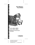
User’s Guide
AHA-3980/3980W/3985/3985W
PCI-to-SCSI MultiChannel RAID Adapters
With SCSISelect
AHA-3980/3980W/3985/3985W User’s Guide
Stock Number: 510810-00, Rev. D
Page: Front Cover
Print Spec Number: 493479-00
Current Date: 3/1/99
ECN Date: 3/19/96
Adaptec, Inc.
691 South Milpitas Boulevard
Milpitas, CA 95035
Copyright © 1996 Adaptec, Inc.
All rights reserved. Adaptec, the Adaptec
logo, and SCSISelect are trademarks of
Adaptec, Inc. which may be registered in
some jurisdictions.
Printed in Singapore
STOCK NO.: 510810-00, Rev. D RF 3/96
AHA-3980/3980W/3985/3985W User’s Guide
Stock Number: 510810-00, Rev. D
Page: Back Cover
Print Spec Number: 493479-00
Current Date: 3/1/99
ECN Date: 3/19/96
▼ ▼ ▼ ▼
AHA-3980/3980W
/3985/3985W
PCI-to-SCSI MultiChannel RAID Adapters
with SCSISelect
User’s Guide
R
AHA-3980/3980W/3985/3985W User’s Guide
Stock Number: 510810-00, Rev. D
Page: i
Print Spec Number: 493479-00
Current Date: 3/1/99
ECN Date: 3/19/96
Copyright
Copyright © 1996 Adaptec, Inc. All rights reserved. No part of this publication may
be reproduced, stored in a retrieval system, or transmitted in any form or by any
means, electronic, mechanical, photocopying, recording or otherwise, without the
prior written consent of Adaptec, Inc., 691 South Milpitas Blvd., Milpitas, CA 95035.
Trademarks
Adaptec, the Adaptec logo, AHA, MultiChannel, and SCSISelect are trademarks of
Adaptec, Inc. which may be registered in some jurisdictions.
All other trademarks are owned by their respective owners.
Changes
The material in this document is for information only and is subject to change without notice. While reasonable efforts have been made in the preparation of this document to assure its accuracy, Adaptec, Inc. assumes no liability resulting from errors or
omissions in this document, or from the use of the information contained herein.
Adaptec reserves the right to make changes in the product design without reservation
and without notification to its users.
Adaptec Technical Support and Services
If you have questions about installing or using the host adapter, check this installation
guide first—you will find answers to most of your questions here. If you need further
assistance, please contact us. We offer the following support and information services:
■
For technical support, for information about the Adaptec World Wide Web
(WWW) and File Transfer Protocol (FTP) Servers, the Adaptec forum on
CompuServe, the Adaptec USA Bulletin Board Service (BBS), and for access to the
Interactive Fax system, call 800-959-SCSI (7274) or 408-945-2550, 24 hours a day,
7 days a week. To speak with a product support representative, call 408-934-SCSI
(7274), M–F: 6:00 a.m. to 5:00 p.m., Pacific Time; after these hours, on weekends,
and on holidays, product support is also available for a fee at 800-416-8066.
–
The Adaptec WWW and FTP Servers, and the Adaptec forum on CompuServe
provide product literature, answers to commonly asked questions, and information on software upgrades and other topics. The WWW and FTP Servers are
available from the Internet 24 hours a day, 7 days a week, at http://
www.adaptec.com and ftp.adaptec.com. To access the Adaptec forum on
CompuServe 24 hours a day, 7 days a week, type GO ADAPTEC.
–
The Adaptec BBS provides answers to commonly asked questions and information on software upgrades and other topics. The BBS is available 24 hours a
day, 7 days a week, at 408-945-7727; 1200/2400/9600/14,400/28,800 baud, 8
data bits, 1 stop bit, no parity.
–
The Adaptec Interactive Fax system provides product literature, answers to
commonly asked questions, and current information about Adaptec products
and services. The Adaptec Interactive Fax system is available 23 hours a day, 7
days a week. The Fax system is out of service 1 hour each day. You can call this
service directly at 408-957-7150.
■
For sales information, call 800-959-SCSI (7274) or 408-945-2550, M–F: 6:00 a.m. to
5:00 p.m., Pacific Time.
■
To order Adaptec software and SCSI cables, call 800-442-SCSI (7274) or
408-957-SCSI (7274), M–F: 6:00 a.m. to 5:00 p.m., Pacific Time.
ii
AHA-3980/3980W/3985/3985W User’s Guide
Stock Number: 510810-00, Rev. D
Page: ii
Print Spec Number: 493479-00
Current Date: 3/1/99
ECN Date: 3/19/96
■
To request additional documentation for Adaptec products, call 800-934-2766 or
510-732-3829, M–F: 6:00 a.m. to 5:00 p.m., Pacific Time.
FCC Compliance Statement
This equipment has been tested and found to comply with the limits for a Class B digital device,
pursuant to Part 15 of the FCC rules. These limits are designed to provide reasonable protection
against harmful interference in residential installations. This equipment generates, uses, and can
radiate radio frequency energy, and if not installed and used in accordance with the instructions,
may cause harmful interference to radio communications. However, there is no guarantee that
interference will not occur in a particular installation.
If this equipment does cause interference to radio or television equipment reception, which can be
determined by turning the equipment off and on, the user is encouraged to try to correct the interference by one or more of the following measures:
• Reorient or relocate the receiving antenna
• Move the equipment away from the receiver
• Plug the equipment into an outlet on a circuit different from that to which the receiver is
powered
• If necessary, the user should consult the dealer or an experienced radio/television technician
for additional suggestions
CAUTION: Only equipment certified to comply with Class B (computer input/output devices,
terminals, printers, etc.) should be attached to this equipment, and must have shielded interface
cables.
Finally, any changes or modifications to the equipment by the user not expressly approved by the
grantee or manufacturer could void the user’s authority to operate such equipment.
Each host adapter is equipped with an FCC compliance label that shows only the FCC identification number. The full text of the associated label follows:
This device complies with part 15 of the FCC rules. Operation is subject to the following two conditions: (1) this device may not cause harmful interference and (2) this device must accept any
interference received, including interference that may cause undesired operation.
Canadian Compliance Statement
This Class B apparatus meets all requirements of the Canadian Interference-Causing Equipment
Regulations.
Cet appareil numérique de la classe B respecte toutes les exigences du Règlement sur le matérial
brouilleur du Canada.
iii
AHA-3980/3980W/3985/3985W User’s Guide
Stock Number: 510810-00, Rev. D
Page: iii
Print Spec Number: 493479-00
Current Date: 3/1/99
ECN Date: 3/19/96
AHA-3980/3980W/3985/3985W User’s Guide
Stock Number: 510810-00, Rev. D
Page: iv
Print Spec Number: 493479-00
Current Date: 3/1/99
ECN Date: 3/19/96
▼ ▼ ▼ ▼
Contents
1 Getting Started
System Requirements 1-2
Using This Document 1-3
Conventions 1-4
Advisories 1-4
PART 1: Learning the Basics
2 Array Basics
Array Types 2-1
RAID 0 (Striped Disks) 2-1
RAID 1, RAID 1/0 (Mirrored Disks) 2-2
RAID 5 2-2
RAID 0 CVT and RAID 5 CVT 2-3
Disk Requirements 2-3
Number of Disks in an Array 2-3
Mixing Disks from Different Manufacturers or with
Different Capacities 2-4
Mixing Disks on Different RAID Adapter Channels 2-4
3 Understanding the Adaptec RAID Software
Adaptec Initial Array Configuration Utility 3-1
The Administrator Utility 3-2
The Adaptec CI/O Software 3-2
The Copy Drivers Utility 3-3
DOS and NetWare Device Drivers 3-3
4 Understanding the AHA-398x Adapter
Multiple Independent Channels 4-1
Standard SCSI and SCSI-2 Features 4-2
v
AHA-3980/3980W/3985/3985W User’s Guide
Stock Number: 510810-00, Rev. D
Page: v
Print Spec Number: 493479-00
Current Date: 3/1/99
ECN Date: 3/19/96
AHA-3980/3980W/3985/3985W User’s Guide
Synchronous and Asynchronous Data Transfers 4-2
The SCSISelect Configuration Utility 4-3
NetWare and DOS Support 4-3
Upgrading Your AHA-3980/3985 Adapter 4-3
Supported SCSI Devices 4-4
Devices Supported under NetWare 4-4
Devices Supported under MS-DOS 4-4
PART 2: Setting Up Arrays
5 Installing the AHA-398x and the SCSI Drives
AHA-398x Layout 5-2
Installing the AHA-398x in a PCI Slot 5-3
Connecting SCSI Devices 5-5
Choosing SCSI Cables 5-7
Connecting Internal SCSI Devices 5-7
Connecting External SCSI Devices 5-10
Terminating the SCSI Bus 5-12
Terminating Channels B and C 5-13
Terminating Channel A 5-14
Setting SCSI IDs and Preparing a Boot Device 5-15
Connecting the SCSI Bus Activity Light 5-16
Installing Multiple Adapters 5-17
Sharing SCSI Devices with a Second Computer 5-18
Completing AHA-398x Installation 5-20
6 Preparing a Boot Device and Installing Drivers
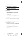
Getting Ready to Prepare a Boot Device 6-1
Creating an Array with the Initial Array Configuration
Utility 6-3
Formatting and Partitioning the Array or Drive 6-7
Copying Drivers 6-8
Installing NetWare on a New Server 6-9
NetWare 3.11 6-9
NetWare 3.12 6-9
vi
AHA-3980/3980W/3985/3985W User’s Guide
Stock Number: 510810-00, Rev. D
Page: vi
Print Spec Number: 493479-00
Current Date: 3/1/99
ECN Date: 3/19/96
Contents
NetWare 4.xx 6-11
Other Initial Array Configuration Utility Options 6-14
Displaying Array Information 6-14
Deleting an Array 6-15
Replacing an Array Drive 6-16
Initializing an Array 6-16
PART 3: Managing Arrays
7 Understanding the Administrator Utility
Starting the Administrator Utility 7-2
Exiting the Administrator Utility 7-2
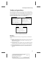
The Main and System Menus 7-3
Main Menu 7-3
System Menu 7-5
Selecting Menu Options 7-5
Grayed Menu Options 7-6
Getting Help 7-6
8 Monitoring Array Performance
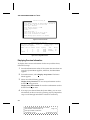
Obtaining Array Information 8-1
Displaying Overview Information 8-2
Displaying Performance Statistics 8-3
Displaying Volume Information 8-4
Changing the Data Sampling Rate 8-4
Resetting the Temporary Statistics to Zero 8-4
Saving the Statistics in the Log File 8-5
Determining Who Receives Messages 8-5
Setting the Repeat Interval for Error Messages 8-7
The Log File 8-8
9 Managing Arrays
Verifying Arrays 9-1
Assigning a Priority 9-2
Verifying an Array Immediately 9-2
vii
AHA-3980/3980W/3985/3985W User’s Guide
Stock Number: 510810-00, Rev. D
Page: vii
Print Spec Number: 493479-00
Current Date: 3/1/99
ECN Date: 3/19/96
AHA-3980/3980W/3985/3985W User’s Guide
Verifying an Array at a Scheduled Time 9-3
Canceling a Verification 9-3
Changing the Priority of a Verification in Progress 9-4
Testing Spare Disks 9-4
Reconstructing Data on a Replacement Disk 9-4
Reconstructing the Data Immediately 9-5
Reconstructing the Data at a Scheduled Time 9-6
Canceling Reconstruction 9-6
Changing the Priority for Reconstructing Data 9-6
Reactivating an Off-line Array 9-7
Scheduling Tasks 9-7
Scheduling a Task 9-7
Changing the Schedule 9-9
Deleting a Scheduled Task 9-9
Using the Hardware Functions 9-9
Identifying the Allocation of Host Adapter Drives 9-9
Locating a Drive 9-10
Pausing Host Adapter Activity When Replacing
Disks 9-11
10 Changing Array Configurations
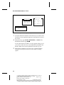
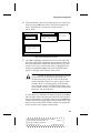
Adding an Array 10-1
Modifying an Array 10-5
Changing the RAID Level 10-5
Selecting Different Disks for the Array 10-6
Adding a Spare Disk 10-6
Deleting a Spare Disk 10-7
Converting between RAID 0 CVT and RAID 5 CVT 10-7
Canceling a Conversion 10-9
Changing the Priority of a Conversion in Progress 10-9
Deleting Arrays and Deinstalling NLMs 10-10
Deleting an Array 10-10
Deinstalling NLMs 10-10
Installing the Array Utilities in the sys:system
Directory 10-11
viii
AHA-3980/3980W/3985/3985W User’s Guide
Stock Number: 510810-00, Rev. D
Page: viii
Print Spec Number: 493479-00
Current Date: 3/1/99
ECN Date: 3/19/96
Contents
11 Initializing Arrays
Choosing the Initialization Method 11-1
Choosing the Data Block Size 11-2
Reinitializing an Array 11-2
12 Working from a Remote Workstation
Standard Adaptec CI/O Features 12-1
Adaptec CI/O Features When Working with the
Administrator Utility 12-2
Enabling a Remote Workstation to Receive Administrator
Utility Data 12-3
Remotely Accessing the Administrator Utility 12-4
PART 4: Advanced Hardware Topics
13 Configuring the Adapter with SCSISelect
Default AHA-398x Settings 13-1
Basic Channel Settings 13-2
Host Adapter (Channel) SCSI ID 13-2
SCSI Parity Checking 13-3
Host Adapter SCSI Termination 13-3
Individual Settings for Each SCSI Device 13-3
Initiate Sync Negotiation 13-3
Maximum Sync Transfer Rate 13-4
Enable Disconnection 13-4
Send Start Unit Command 13-5
Include in BIOS Scan 13-5
Initiate Wide Negotiation (AHA-3980W/3985W
only) 13-5
SCSISelect Basics 13-6
Starting SCSISelect 13-6
Using SCSISelect Menus 13-7
Exiting SCSISelect 13-7
Changing the AHA-398x Settings 13-7
Listing SCSI IDs 13-11
ix
AHA-3980/3980W/3985/3985W User’s Guide
Stock Number: 510810-00, Rev. D
Page: ix
Print Spec Number: 493479-00
Current Date: 3/1/99
ECN Date: 3/19/96
AHA-3980/3980W/3985/3985W User’s Guide
Formatting a SCSI Disk 13-11
Verifying a Disk 13-12
14 Using a CD-ROM Drive
Using a CD-ROM Drive under DOS 14-1
Using a CD-ROM Drive under NetWare 14-5
A Hardware Troubleshooting
Troubleshooting Checklist A-1
Startup Diagnostics A-2
BIOS Startup Messages A-3
aha3980.dsk Error Messages A-6
Disk Drive Configuration Problems A-7
Booting the Computer from a SCSI Drive A-8
Using a Standard Drive as C and a SCSI Drive as D A-8
Using SCSI Drives as C and D A-9
Computer Hangs, or Channel Cannot Always Find the
Drives A-9
Other Problems and Solutions A-10
B Software Error Messages
C Glossary of RAID Software
NetWare Drivers C-1
NetWare Loadable Modules C-2
Other Files C-4
❒
x
AHA-3980/3980W/3985/3985W User’s Guide
Stock Number: 510810-00, Rev. D
Page: x
Print Spec Number: 493479-00
Current Date: 3/1/99
ECN Date: 3/19/96
▼ ▼ ▼ ▼
1
Getting Started
This User’s Guide explains how to install and use the Adaptec
AHA-398x family of MultiChannel PCI-to-SCSI RAID adapters,
which are designed to provide powerful disk array support in
NetWare servers that have a PCI (Peripheral Component Interconnect) bus. Each AHA-398x adapter has either two or three SCSI channels; each channel has the equivalent functionality of a separate SCSI
bus. You can easily configure the adapter to boot the server from a
single SCSI disk drive or from an array.
There are four adapter models in the AHA-398x family:
■
The AHA-3980 adapter has two Fast SCSI channels and supports up to 14 SCSI devices
■
The AHA-3980W adapter has two Fast and Wide SCSI channels and supports up to 30 SCSI devices
■
The AHA-3985 adapter has three Fast SCSI channels and supports up to 21 SCSI devices
■
The AHA-3985W adapter has three Fast and Wide SCSI channels and supports up to 45 SCSI devices
AHA-398x adapters include software that helps you configure and
use arrays and other devices connected to the adapter. You use the
DOS-based Adaptec Initial Array Configuration Utility to prepare
an initial array and to make it bootable. You use the Copy Drivers
Utility to set up drivers for NetWare and for CD-ROM drives. You
use the console-based Administrator Utility, which runs under
NetWare, to add, delete, reconfigure, and manage arrays on an
ongoing basis.
1-1
AHA-3980/3980W/3985/3985W User’s Guide
Stock Number: 510810-00, Rev. D
Page: 1-1
Print Spec Number: 493479-00
Current Date: 3/1/99
ECN Date: 3/19/96
AHA-3980/3980W/3985/3985W User’s Guide
The CI/O software allows you to monitor and manage the network
from remote workstations.
System Requirements
The AHA-398x RAID adapter and software must be installed on a
NetWare server that has the following system resources:
Hardware/Firmware
■
An 80486DX or Pentium computer that complies with PCI
Rev. 2.0
■
A motherboard BIOS that supports PCI-to-PCI bridges, a
64-KByte BIOS, and multiple interrupts
If you are not sure which features the BIOS supports, contact
your vendor, or call Adaptec’s Interactive Fax Service for a list
of compatible motherboards. See Adaptec Technical Support and
Services on page ii.
■
An available full-length PCI slot that supports bus mastering
and PCI Int B
■
A 3.5-inch 1.44-MByte primary (boot) floppy disk drive
■
A minimum of two SCSI disks for a RAID 0 or mirrored array;
a minimum of three SCSI disks for a RAID 0 CVT, RAID 5, or
RAID 5 CVT array (see Number of Disks in an Array on page 2-3)
■
Two MBytes of hard disk space for the Adaptec RAID software
Software
■
NetWare 386, version 3.11, 3.12, or 4.xx
■
NetWare CLIB 3.12 or higher
■
MS DOS 5.0 or above (MS-DOS 6.0 or above recommended)
■
The Adaptec Initial Array Configuration Utility and AHA-3980/
3985 Drivers and RAID Utilities diskettes, which are included
with the AHA-398x
■
To run CD-ROM drives under MS-DOS 5.0: The Microsoft
CD-ROM extension, mscdex.exe, which is included with
MS-DOS 6.0 or above. (This file is also available on Microsoft’s
electronic bulletin board)
1-2
AHA-3980/3980W/3985/3985W User’s Guide
Stock Number: 510810-00, Rev. D
Page: 1-2
Print Spec Number: 493479-00
Current Date: 3/1/99
ECN Date: 3/19/96
Getting Started
If you intend to use Adaptec CI/O, it must be installed on the
remote workstation from which you plan to monitor the arrays. See
the Adaptec CI/O documentation to learn the hardware and software requirements for the remote workstation.
Using This Document
To use this document, first read Part 1 to learn the basics of arrays
and how they are supported by AHA-398x host adapters and the
supporting software. Part 1 also includes an overview of adapter
features and of the software included with the adapter. Pay particular attention to System Requirements on page 1-2.
Next, follow the instructions in Part 2 to physically install the
AHA-398x in your computer, attach the SCSI devices, prepare a boot
array or boot drive, and copy DOS and NetWare drivers to the
server.
Read Chapter 7 in Part 3 to learn the basics of the Administrator
Utility, which runs under NetWare. Then follow the instructions in
the rest of Part 3, as needed, to learn how to use this utility to monitor array performance, manage your arrays, change array configurations, add new arrays, and format arrays. Chapter 12 explains how
to use Adaptec CI/O to monitor your arrays from a remote
workstation.
Read Part 4 as needed to learn how to use the SCSISelect utility to
change AHA-398x configuration parameters and how to set up a
CD-ROM drive to install NetWare and other software.
Appendices A and B have troubleshooting information. Appendix C
describes the drivers and other RAID-related software included
with the AHA-398x.
1-3
AHA-3980/3980W/3985/3985W User’s Guide
Stock Number: 510810-00, Rev. D
Page: 1-3
Print Spec Number: 493479-00
Current Date: 3/1/99
ECN Date: 3/19/96
AHA-3980/3980W/3985/3985W User’s Guide
Conventions
The following typographic conventions are used in this document:
bold
Used for key names (… press the Enter key …) and for options
you are directed to select (… select SCSI Disk Utilities …).
Helvetica
Used for screen messages (…Save changes?…) and for text
you must type exactly as shown.
Helvetica Italics
Used for program and file names when referenced in the text
(… aspi8dos …).
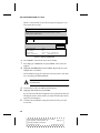
Advisories
Advisories are quick notes that stress an important point or warn of
a potential hazard to the system or data. This document has three
kinds of advisories:
Note: Text set off in this way presents reminders, tips, or suggestions that may simplify the use of the AHA-398x.
Caution: Failure to observe this type of advisory could result
in damage to your system, devices, or data.
WARNING: Failure to observe this type of advisory could
result in personal injury.
Use caution when handling any electrical equipment. Advisories in
this document can only cover the procedures contained here, and
not all situations may have been addressed. Adaptec does not claim
to have included every condition or situation that might require a
Caution or Warning. You must refer to the documentation for your
computer and peripheral devices when you are installing equipment
or changing its configuration.
❒
1-4
AHA-3980/3980W/3985/3985W User’s Guide
Stock Number: 510810-00, Rev. D
Page: 1-4
Print Spec Number: 493479-00
Current Date: 3/1/99
ECN Date: 3/19/96
▼ ▼ ▼ ▼
Part 1
Learning the Basics
AHA-3980/3980W/3985/3985W User’s Guide
Stock Number: 510810-00, Rev. D
Page: Part 1-v
Print Spec Number: 493479-00
Current Date: 3/1/99
ECN Date: 3/19/96
AHA-3980/3980W/3985/3985W User’s Guide
Stock Number: 510810-00, Rev. D
Page: Part 1-vi
Print Spec Number: 493479-00
Current Date: 3/1/99
ECN Date: 3/19/96
▼ ▼ ▼ ▼
2
Array Basics
Adaptec’s RAID adapter and RAID software let you set up and manage disk arrays on NetWare servers. A disk array is a group of disks
that appears to the system as a single virtual disk. This is accomplished through software. RAID (Redundant Array of Inexpensive
Disks) refers to disk arrays in which part of the array storage capacity may be used to store redundant information. The redundant
information lets you restore user data if a disk in the array fails.
A virtual disk is functionally identical to a physical disk. Depending
on the array type, however, the virtual disk has advantages in faulttolerance, cost, performance, or a combination of these. This chapter
explains the different array types and the disk requirements for each
type.
Array Types
Array types are defined by their RAID level, a number from 0
through 6 (a higher RAID level does not indicate a higher level of
performance or fault-tolerance). Adaptec RAID software lets you
create the types of arrays that have proven to be the most useful for
NetWare RAID applications: RAID 0, 1, 1/0, and 5.
RAID 0 (Striped Disks)
In a RAID 0 array, data is distributed, or striped, across the disks in
the array. The array appears to the server as one large disk with a
capacity approximately equal to the combined capacity of the physical disks. Because multiple reads and writes can be handled in parallel, the input/output performance of the array is much better than
that of a single physical disk.
2-1
AHA-3980/3980W/3985/3985W User’s Guide
Stock Number: 510810-00, Rev. D
Page: 2-1
Print Spec Number: 493479-00
Current Date: 3/1/99
ECN Date: 3/19/96
AHA-3980/3980W/3985/3985W User’s Guide
RAID 0 arrays do not store redundant data, so they are not true
RAID applications. If one disk fails, the entire array fails and all array
data is lost. The fault-tolerance of a RAID 0 array, therefore, is less
than that of any single disk in the array. The term RAID 0 is widely
used for these arrays, however, because they are conceptually similar
to true RAID applications.
RAID 1, RAID 1/0 (Mirrored Disks)
In RAID 1 and RAID 1/0 arrays (commonly called mirrored arrays)
disks are paired, with both disks in a pair containing the same data.
When data is written to a mirrored array, it is written twice—once to
each disk in the pair. A RAID 1 array has only one set of paired disks.
A RAID 1/0 array has multiple pairs, across which data is striped.
The read performance of RAID 1 arrays can be much better than that
of a single disk, while the write performance is slightly worse. In
RAID 1/0 arrays, both read performance and write performance are
better than those of a single disk.
A mirrored array is also highly reliable, because both disks in a pair
must fail for the array to fail. In an array with five pairs of mirrored
disks, for example, the array can maintain its integrity if even five
disks fail—as long as each pair is left with one good disk. The main
disadvantage of a mirrored array is its cost. Because all disks must
have a twin, you must use twice the number of disks that actually
contribute to the array capacity. In an eight-disk array, for example,
you have only four disks of usable capacity.
RAID 5
RAID 5 arrays contain redundant information in the form of parity
data, which is calculated block by block for all user data. The parity
information is distributed across the disks in the array, as in RAID 0
arrays, and occupies the equivalent capacity of about one disk. Data
is interspersed with the parity information. If one disk in the array
fails, the data on the failed disk can be reconstructed from the parity
data and user data on the remaining disks. Two disks must fail
before the entire array fails.
The read performance of a RAID 5 array is excellent—comparable to
that of a RAID 0 array. Write performance is lower than that of a
RAID 0 array, because write operations involve calculating and writing new parity data as well as writing the new user data.
2-2
AHA-3980/3980W/3985/3985W User’s Guide
Stock Number: 510810-00, Rev. D
Page: 2-2
Print Spec Number: 493479-00
Current Date: 3/1/99
ECN Date: 3/19/96
Array Basics
RAID 0 CVT and RAID 5 CVT
RAID 0 CVT and RAID 5 CVT arrays are functionally identical to
RAID 0 and RAID 5 arrays, but you can convert from a RAID 0 CVT
array to a RAID 5 CVT array and back again without loss of data
and without reformatting. The CVT formats allow you to use the
more reliable RAID 5 format for normal use, then switch to RAID 0,
which has higher write performance, for large data transfers (for
example, restoring data from tape). After the data is transferred, you
can convert back to the RAID 5 CVT format.
Note: For more information on RAID levels, see The RAID
Book: A Source Book for RAID Technology, published by the
RAID Advisory Board (Lino Lakes, Minnesota: September,
1994).
Disk Requirements
An Adaptec array is an array that was set up using Adaptec’s RAID
software. Adaptec’s RAID software lets you create up to four bootable or nonbootable arrays of SCSI disks. The following sections
describe the disk requirements of Adaptec arrays.
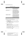
Number of Disks in an Array
The following table shows the number of SCSI disks allowed in each
type of Adaptec array. The disks can be connected to different channels of the same RAID adapter; however, they cannot be on different
RAID adapters.
RAID Level
RAID 0 (striped)
RAID 0 CVT
Mirrored:
RAID 1
RAID 1/01
RAID 5
RAID 5 CVT
Minimum No.
of Disks
2
3
Maximum No.
of Disks
8
8
2
4
3
3
2
16
8
8
1 The number of drives in a RAID 1/0 array must be even.
2-3
AHA-3980/3980W/3985/3985W User’s Guide
Stock Number: 510810-00, Rev. D
Page: 2-3
Print Spec Number: 493479-00
Current Date: 3/1/99
ECN Date: 3/19/96
AHA-3980/3980W/3985/3985W User’s Guide
In addition to the main disks, you can specify up to two spare disks
(spares) for mirrored and RAID 5 arrays. (RAID 0 arrays do not have
spares.) Spares are automatically activated when an array disk fails.
A spare must have at least the capacity of the smallest disk in the
array.
Mixing Disks from Different Manufacturers or with Different
Capacities
An array can contain different models of SCSI disks, even disks with
different capacities; for example, an array can include a Quantum
340 MByte disk and a Conner 540 MByte disk. If you mix disks with
different capacities, however, the smallest disk determines the logical capacity of all other disks in the array (regardless of RAID level).
If a RAID 0 array contains one 340 MByte disk and four 540 MBytes
disks, for example, the capacity of the array is equivalent to about
five 340 MByte disks. To avoid wasted disk capacity, therefore, use
disks of similar size.
Mixing Disks on Different RAID Adapter Channels
An AHA-3980/3980W RAID adapter has two channels: A and B. An
AHA-3985/3985W RAID adapter has three channels: A, B, and C.
Each channel acts as an independent RAID adapter, implementing a
separate SCSI bus. An array can consist of disks on different channels of the same RAID adapter; however, it cannot include disks
from two or more RAID adapters installed in the server.
❒
2-4
AHA-3980/3980W/3985/3985W User’s Guide
Stock Number: 510810-00, Rev. D
Page: 2-4
Print Spec Number: 493479-00
Current Date: 3/1/99
ECN Date: 3/19/96
▼ ▼ ▼ ▼
3
Understanding the Adaptec
RAID Software
You use Adaptec’s RAID software to set up and manage up to four
bootable or nonbootable arrays. The following RAID software is
included with your AHA-398x adapter:
■
Adaptec Initial Array Configuration Utility
■
Administrator Utility
■
Adaptec CI/O Software
■
Copy Drivers Utility
■
DOS and NetWare Device Drivers
This section gives an overview of each part of the software and
explains where to look for more information.
Adaptec Initial Array Configuration Utility
Use the DOS-based Adaptec Initial Array Configuration Utility to
create a bootable array, if you want to boot your server from an
array. You can also use this utility to create other nonbootable arrays,
delete arrays, view array information, replace a drive in an existing
array, and reinitialize an array.
The Initial Array Configuration Utility is described in detail in
Chapter 6, Preparing a Boot Device and Installing Drivers.
3-1
AHA-3980/3980W/3985/3985W User’s Guide
Stock Number: 510810-00, Rev. D
Page: 3-1
Print Spec Number: 493479-00
Current Date: 3/1/99
ECN Date: 3/19/96
AHA-3980/3980W/3985/3985W User’s Guide
The Administrator Utility
The NetWare-based Administrator utility lets you create and manage arrays. You can use this utility to
■
Create up to four nonbootable arrays (to create bootable
arrays, you must use the Adaptec Initial Array Configuration
Utility)
■
Format arrays
■
Add, modify, or delete arrays
■
View array information
■
Perform routine management tasks such as testing spare disks,
verifying the integrity of arrays, regenerating data on replacement disks, and reactivating off-line arrays
See Part 3 for information about the Administrator utility and
instructions on how to use it.
Note: Depending on the task, the Administrator utility may
call other utilities, such as the Format utility. This happens
in the background, so you do not need to understand the
other utilities. If you are curious about these utilities, however, see Appendix C, Glossary of RAID Software.
The Adaptec CI/O Software
Use Adaptec CI/O to monitor SCSI subsystems, including Adaptec
arrays, from a remote workstation. Adaptec CI/O also lets you
remotely access the Administrator utility, making all Administrator
utility functions available at the remote workstation. For an overview of Adaptec CI/O capabilities, see Chapter 12, Working from a
Remote Workstation. This chapter also explains how to set up the
Adaptec RAID software for use with Adaptec CI/O.
AHA-398x RAID adapter kits include Adaptec CI/O (the single
server version). If you purchased the RAID adapter separately, you
can obtain Adaptec CI/O by calling the sales order line at the number listed on page ii.
3-2
AHA-3980/3980W/3985/3985W User’s Guide
Stock Number: 510810-00, Rev. D
Page: 3-2
Print Spec Number: 493479-00
Current Date: 3/1/99
ECN Date: 3/19/96
Understanding the Adaptec RAID Software
The Copy Drivers Utility
Use the DOS-based Copy Drivers Utility to copy DOS and NetWare
drivers from the AHA-3980/3985 Drivers and RAID Utilities diskette to the server’s hard disk drive. The drivers are automatically
copied to the appropriate directory. You may need to edit your
config.sys, autoexec.bat, or startup.ncf files in order to load the
drivers.
The Copy Drivers Utility is described in detail in Copying Drivers on
page 6-8.
DOS and NetWare Device Drivers
You must use the Copy Drivers Utility to copy Adaptec device drivers for DOS and NetWare to your hard disk. The AHA-3980/3985
Drivers and RAID Utilities diskette includes files for NetWare 3.11,
3.12, and 4.xx. Also, DOS CD-ROM drivers are included so you can
connect a SCSI CD-ROM drive to the AHA-398x host adapter and
use it to load operating system software.
❒
3-3
AHA-3980/3980W/3985/3985W User’s Guide
Stock Number: 510810-00, Rev. D
Page: 3-3
Print Spec Number: 493479-00
Current Date: 3/1/99
ECN Date: 3/19/96
AHA-3980/3980W/3985/3985W User’s Guide
Stock Number: 510810-00, Rev. D
Page: 3-4
Print Spec Number: 493479-00
Current Date: 3/1/99
ECN Date: 3/19/96
▼ ▼ ▼ ▼
4
Understanding the
AHA-398x Adapter
Adaptec’s AHA-398x adapter is a multichannel PCI-to-SCSI RAID
adapter for disk arrays. As a host adapter, the AHA-398x provides
the interface between your computer’s PCI bus and your SCSI
drives. As a RAID adapter, the AHA-398x lets you create and operate arrays of SCSI disks. The AHA-398x has special onboard features
that speed many RAID read and write operations.
Multiple Independent Channels
Each AHA-3980/3980W adapter has two SCSI channels: A and B.
Each AHA-3985/3985W adapter has three channels: A, B, and C.
Each channel functions as an independent RAID adapter.
The AHA-3980 and AHA-3985 are 8-bit adapters. Each channel on
these adapters supports up to seven 8-bit Fast SCSI devices. The
AHA-3980W and AHA-3985W are 16-bit adapters. Each channel on
these adapters supports up to 15 SCSI devices. All 15 devices can be
16-bit, or you can combine 8-bit and 16-bit devices. If you combine
devices, a maximum of seven can be 8-bit devices.
The channels have the following connectors:
■
Channel A: One internal and one external SCSI connector
■
Channel B: One internal SCSI connector
■
Channel C (AHA-3985/3985W only): One internal SCSI
connector
4-1
AHA-3980/3980W/3985/3985W User’s Guide
Stock Number: 510810-00, Rev. D
Page: 4-1
Print Spec Number: 493479-00
Current Date: 3/1/99
ECN Date: 3/19/96
AHA-3980/3980W/3985/3985W User’s Guide
Standard SCSI and SCSI-2 Features
AHA-398x adapters support all SCSI functions supported by
Adaptec’s other host adapters, including the following SCSI-2
features:
■
Scatter/Gather: Allows high performance even in computers
with fragmented memory buffers
■
Disconnect/Reconnect: Maximizes SCSI bus usage in systems
with multiple targets
■
Tagged Command Queuing: Allows a SCSI device to return
data in a different order than that requested by the adapter
In addition, AHA-398x adapters
■
Provide continuous termination power to the SCSI bus
■
Let you enable or disable SCSI termination for each separate
AHA-398x channel
■
Generate and check parity on the SCSI bus. Parity checking can
be disabled if a device on the bus does not support it (see
Chapter 13, Configuring the Adapter with SCSISelect).
Synchronous and Asynchronous Data Transfers
The AHA-398x allows both synchronous and asynchronous data
transfers on a channel. The maximum transfer speeds are as follows:
■
AHA-3980/3985 Synchronous: Up to 10.0 MBytes/sec per
channel
■
AHA-3980/3985 Asynchronous: Up to 3.0 MBytes/sec per
channel
■
AHA-3980W/3985W Synchronous: Up to 20.0 MBytes/sec per
channel
■
AHA-3980W/3985W Asynchronous: Up to 6.0 MBytes/sec per
channel
By default, the AHA-398x negotiates for synchronous transfers with
each device; you can disable synchronous negotiation for devices
that accept only asynchronous transfers (see Chapter 13, Configuring
the Adapter with SCSISelect). The AHA-398x always accepts negotiations for synchronous transfers initiated by a SCSI device.
4-2
AHA-3980/3980W/3985/3985W User’s Guide
Stock Number: 510810-00, Rev. D
Page: 4-2
Print Spec Number: 493479-00
Current Date: 3/1/99
ECN Date: 3/19/96
Understanding the AHA-398x Adapter
The SCSISelect Configuration Utility
The AHA-398x includes the onboard SCSISelect configuration utility.
SCSISelect allows you to change AHA-398x settings, such as channel
termination and parity checking, without changing switches or
jumpers on the board. SCSISelect also provides utilities for formatting SCSI disk devices and scanning them for defects. See Chapter
13, Configuring the Adapter with SCSISelect.
NetWare and DOS Support
The AHA-398x is intended primarily to support disk arrays on systems operating under NetWare 3.11, 3.12, or 4.xx. However, it also
supports SCSI hard drives and CD-ROM drives operating under
MS-DOS 5.0 or above. Limited disk array functionality is supported
under DOS, including RAID 5 operation with a failed drive.1 The
DOS support also allows you to install NetWare from a CD-ROM
drive attached to the AHA-398x. (The DOS-based NetWare installation program is usually distributed on CD-ROM.)
The AHA-398x package includes NetWare software drivers. It also
includes drivers needed to operate CD-ROM drives under NetWare
and DOS. The drivers are on a disk labeled AHA-3980/3985 Drivers
and RAID Utilities.
Upgrading Your AHA-3980/3985 Adapter
If you own a previously purchased Adaptec AHA-3980/3985 RAID
adapter with software version 1.01 or earlier, you can obtain a free
upgrade kit from Adaptec to add bootable array support to your
adapter. Contact Adaptec Technical Support for this BIOS and software upgrade kit. The kit includes instructions on how to install the
upgrade.
1 Using
arrays for long-term DOS or Windows operation is not
recommended.
4-3
AHA-3980/3980W/3985/3985W User’s Guide
Stock Number: 510810-00, Rev. D
Page: 4-3
Print Spec Number: 493479-00
Current Date: 3/1/99
ECN Date: 3/19/96
AHA-3980/3980W/3985/3985W User’s Guide
Supported SCSI Devices
AHA-398x RAID adapters support single-ended SCSI devices (to
determine whether a device is single-ended, check the device documentation). AHA-3980/3985 adapters support 8-bit SCSI devices
and AHA-3980W/3985W adapters support both 8-bit and 16-bit
SCSI devices. The following sections describe SCSI device support
under NetWare and under MS-DOS.
Devices Supported under NetWare
The AHA-398x supports all SCSI devices supported by NetWare 386
3.11, 3.12, and 4.xx. This includes SCSI hard drives, tape drives, jukeboxes, and removable-media disk drives (for example, magnetooptical drives). Removable-media drives are treated as standard SCSI
hard disk drives, with these exceptions:
■
The AHA-398x recognizes and registers only media with
512 bytes/sector.
■
You can mount, dismount, lock, and unlock the media. These
options are supported by NetWare’s monitor.nlm program. (See
the NetWare documentation.)
■
Do not use removable media devices in arrays.
To operate CD-ROM drives under NetWare, you must install
aspicd.dsk, the CD-ROM driver for NetWare (see Using a CD-ROM
Drive under NetWare on page 14-5). This driver enables the AHA-398x
to support most popular CD-ROM drives.
Devices Supported under MS-DOS
Under MS-DOS 5.0 and above, the AHA-398x BIOS supports up to
eight standard devices—for example, IDE or EIDE drives —and
SCSI hard drives and arrays without the need for drivers, as long as
the drives support Int 13h. (To verify that your drives support Int 13h,
read your device documentation or check with your vendor.) The
AHA-398x BIOS supports disk drives as large as 8 GBytes.
If you install aspi8dos and aspicd.sys, the AHA-398x also supports
CD-ROM drives. For information on using aspicd.sys, see Using a
CD-ROM Drive under DOS on page 14-1.
❒
4-4
AHA-3980/3980W/3985/3985W User’s Guide
Stock Number: 510810-00, Rev. D
Page: 4-4
Print Spec Number: 493479-00
Current Date: 3/1/99
ECN Date: 3/19/96
▼ ▼ ▼ ▼
Part 2
Setting Up Arrays
AHA-3980/3980W/3985/3985W User’s Guide
Stock Number: 510810-00, Rev. D
Page: Part 2-v
Print Spec Number: 493479-00
Current Date: 3/1/99
ECN Date: 3/19/96
AHA-3980/3980W/3985/3985W User’s Guide
Stock Number: 510810-00, Rev. D
Page: Part 2-vi
Print Spec Number: 493479-00
Current Date: 3/1/99
ECN Date: 3/19/96
▼ ▼ ▼ ▼
5
Installing the AHA-398x
and the SCSI Drives
This chapter explains how to physically install an AHA-398x
adapter in your computer and connect SCSI drives to it. The chapter
takes you through each of the following steps:
■
Installing the AHA-398x in a PCI slot in your computer
■
Connecting the SCSI drives to the AHA-398x
■
Terminating the SCSI bus
■
Setting SCSI IDs and preparing a boot device
■
Connecting the LED light that indicates activity on the
AHA-398x
The chapter also describes special cases such as installing multiple
AHA-398x adapters, combining the AHA-398x with ISA- or EISAbased host adapters, and sharing SCSI devices between two
computers.
AHA-398x RAID adapters are configured to provide optimum performance for most systems. Read Chapter 13, Configuring the Adapter
with SCSISelect, to learn about situations in which you may need to
change the configuration. You can change the configuration after
you install the AHA-398x and attach the SCSI devices.
5-1
AHA-3980/3980W/3985/3985W User’s Guide
Stock Number: 510810-00, Rev. D
Page: 5-1
Print Spec Number: 493479-00
Current Date: 3/1/99
ECN Date: 3/19/96
AHA-3980/3980W/3985/3985W User’s Guide
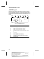
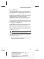
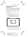
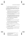
AHA-398x Layout
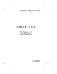
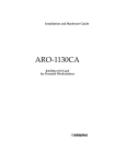
Figures 5-1 and 5-2 (and the tables following each figure) identify
the major AHA-398x components. You may find it helpful to refer to
this information while installing the adapter and attaching the SCSI
devices.
J1 J2
J8
J3
J9
J4
J10
J6
J13
Figure 5-1. AHA-3980/3985 Board Layout
1
Location
Description
J1
External 50-pin high-density SCSI connector - Channel A
J2
Multiple computer termination jumper - Channel A1
J3
Multiple computer termination jumper - Channel B1
J4
(AHA-3985 only) Multiple computer termination jumper - Channel
C1
J6
LED connector
J8
Internal 50-pin SCSI connector - Channel A
J9
Internal 50-pin SCSI connector - Channel B
J10
(AHA-3985 only) Internal 50-pin SCSI connector - Channel C
J13
PCI interrupt jumper
See Sharing SCSI Devices with a Second Computer on page 5-18.
5-2
AHA-3980/3980W/3985/3985W User’s Guide
Stock Number: 510810-00, Rev. D
Page: 5-2
Print Spec Number: 493479-00
Current Date: 3/1/99
ECN Date: 3/19/96
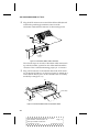
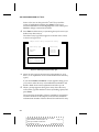
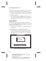
Installing the AHA-398x and the SCSI Drives
J2
J4
J12
J5
J10
J6
J7
J8
J3
Figure 5-2. AHA-3980W/3985W Board Layout
1
Location
Description
J2
Multiple computer termination jumper - Channel A1
J3
LED connector
J4
Internal 68-pin high-density SCSI connector - Channel A
J5
Multiple computer termination jumper - Channel B1
J6
Internal 68-pin high-density SCSI connector - Channel B
J7
(AHA-3985W only) Multiple computer termination jumper - Channel C1
J8
(AHA-3985W only) Internal 68-pin high-density SCSI connector Channel C
J10
PCI interrupt jumper
J12
External SCSI connector - Channel A
See Sharing SCSI Devices with a Second Computer on page 5-18.
Installing the AHA-398x in a PCI Slot
Follow the steps in this section to install the AHA-398x in your computer. Be sure your computer meets the minimum hardware and software
requirements before you begin installation (see System Requirements on
page 1-2).
WARNING: Be sure the power is turned OFF and the computer is unplugged before you continue.
5-3
AHA-3980/3980W/3985/3985W User’s Guide
Stock Number: 510810-00, Rev. D
Page: 5-3
Print Spec Number: 493479-00
Current Date: 3/1/99
ECN Date: 3/19/96
AHA-3980/3980W/3985/3985W User’s Guide
1
Remove the cover from the computer case.
2
Locate an unused, unobstructed 5-volt PCI bus slot that supports bus mastering. PCI bus slots are typically white or ivory
and are shorter than ISA or EISA slots. Usually, there are three
PCI slots. One of these may be a shared slot—that is, it may
have both an ISA connector and a PCI connector—but only one
kind of board can be inserted in the slot at any one time.
Caution: Some slots may be blocked by the host processor. Do not force the AHA-398x into a slot. Many
motherboards only allow one full-length slot. If this
slot is already occupied, move the short card to
another slot.
3
Remove the metal bracket that covers the slot opening in the
computer case. Keep the screw that held the metal bracket in
place; you will need it later.
Caution: Before proceeding with the next step, ground
yourself by touching an unpainted surface on the
computer chassis. Otherwise, you may damage the
AHA-398x.
4
Carefully remove the AHA-398x from its package.
Note: If you need to use PCI interrupts B, C, and D,
remove the PCI interrupt jumper (for the jumper location, see the diagrams on pages 5-2 and 5-3). We recommend that you leave the jumper in place if your
computer supports only PCI interrupts A and B. (This is
the default for most PCI computers.)
5
Position the AHA-398x directly over the PCI slot. If your computer has a card guide to align the AHA-398x, be sure to insert
the end of the adapter in the card guide.
5-4
AHA-3980/3980W/3985/3985W User’s Guide
Stock Number: 510810-00, Rev. D
Page: 5-4
Print Spec Number: 493479-00
Current Date: 3/1/99
ECN Date: 3/19/96
Installing the AHA-398x and the SCSI Drives
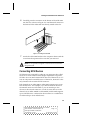
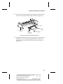
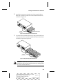
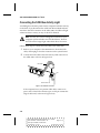
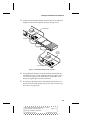
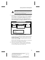
6
Carefully press the connector on the bottom of the AHA-398x
into the slot, as shown in Figure 5-3, until the metal contacts on
the bottom of the AHA-398x are securely seated in the slot.
Figure 5-3. Inserting the AHA-398x
7
Attach the AHA-398x bracket to the computer chassis with the
screw from the expansion slot cover that you removed.
Note: Do not put the computer cover back on or reconnect
the power yet!
Connecting SCSI Devices
SCSI devices are connected by cables in one continuous line called
the SCSI bus. Each channel on the adapter implements a separate
SCSI bus. You can attach internal SCSI devices to Channel A, B, or C.
You can only attach external devices to Channel A, because it is the
only channel with an external SCSI connector.
Each channel on an AHA-3980 or AHA-3985 supports up to seven
8-bit SCSI devices. For example, if you attach two SCSI devices to
the internal connector of Channel A, you can attach up to five
devices to the external connector—a total of seven devices on the
channel. On an AHA-3980W or AHA-3985W, each channel supports
up to 15 SCSI devices—either 16-bit devices alone or a combination
of 16-bit and up to seven 8-bit devices.
5-5
AHA-3980/3980W/3985/3985W User’s Guide
Stock Number: 510810-00, Rev. D
Page: 5-5
Print Spec Number: 493479-00
Current Date: 3/1/99
ECN Date: 3/19/96
AHA-3980/3980W/3985/3985W User’s Guide
This section explains how to connect both internal and external SCSI
devices to the channel connectors. When you attach the SCSI
devices, remember the following constraints:
■
If you combine 8-bit and 16-bit devices on an external
AHA-3980W or AHA-3985W channel, you must attach the
8-bit devices after the 16-bit devices; once you use a 68-to-50-pin
converter to step down to an 8-bit device, you cannot step back
up to a 16-bit device because the high bits are terminated. (You
can order a 68-to-50-pin converter from Adaptec by calling the
phone number listed on page ii.)
■
If you combine 8-bit and 16-bit devices on an internal
AHA-3980W or AHA-3985W channel, you must attach the
8-bit devices before the 16-bit devices.
■
On each channel, the total length of cabling (internal and external) should not exceed
■
–
three meters (9.8 feet) if you use 8-bit or 16-bit Fast SCSI data
transfer rates, such as the default rate
–
six meters (19.7 feet) if you use 5 MByte/sec asynchronous or
synchronous data transfer rates
If you plan to boot the computer from a stand-alone SCSI
drive, connect the drive to Channel A of the adapter. If you
plan to boot the computer from an array, connect at least one of
the drives for this array to Channel A.
Caution: AHA-398x RAID adapters support only single-ended SCSI devices. Differential SCSI devices may be
damaged if you connect them to the AHA-398x bus. Read
your SCSI device documentation to determine whether a
device is single-ended or differential.
5-6
AHA-3980/3980W/3985/3985W User’s Guide
Stock Number: 510810-00, Rev. D
Page: 5-6
Print Spec Number: 493479-00
Current Date: 3/1/99
ECN Date: 3/19/96
Installing the AHA-398x and the SCSI Drives
Choosing SCSI Cables
Always use high-quality SCSI cables to connect the AHA-398x to
devices on the SCSI bus. Poor-quality cables can cause data corruption, parity errors, and other problems. High-quality cabling is especially critical if you use Fast SCSI data transfer rates.
The cables used for external SCSI devices vary widely in quality and
electrical characteristics. Use external SCSI cables that
■
Meet SCSI-2 standards (your cable vendor can tell you this)
■
Have a single-ended impedance range of 80-110 ohms
Adaptec sells high-quality internal and external SCSI-2 cables, which
you can purchase by calling Adaptec at the number listed on page ii.
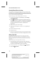
Connecting Internal SCSI Devices
Use the SCSI ribbon cables included with the AHA-398x kit to connect internal devices to the adapter. Each AHA-398x ribbon cable
has several connectors, including connectors at each end of the
cable. The connector at one end is attached to a passthrough terminator (for information on termination, see Terminating the SCSI Bus
on page 5-12). You can attach this connector to a SCSI device, even
with the terminator in place.
Note: If you need more cables, you can purchase them from
Adaptec by calling the number listed on page ii.
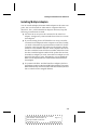
Follow these steps to connect internal SCSI devices to the internal
connectors on the AHA-398x:
1
If you need to physically install the SCSI device inside your
computer before attaching the cables, follow the installation
instructions in the device documentation.
5-7
AHA-3980/3980W/3985/3985W User’s Guide
Stock Number: 510810-00, Rev. D
Page: 5-7
Print Spec Number: 493479-00
Current Date: 3/1/99
ECN Date: 3/19/96
AHA-3980/3980W/3985/3985W User’s Guide
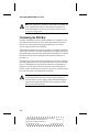
2
Plug the SCSI connector at one end of the ribbon cable (the end
without the passthrough terminator) into one of the
AHA-398x’s internal SCSI connectors, as shown in Figure 5-4.
Colored
Stripe
SCSI
Ribbon Cable
1
Pin 1
Internal SCSI
Connector
Figure 5-4. Internal SCSI Ribbon Cable to AHA-398x
The colored stripe on one side of the ribbon cable must match
up with the number 1 printed on the AHA-398x beneath the
connector. This is called maintaining proper pin-1 orientation.
3
Plug a SCSI connector on the internal cable to the SCSI connector on the first SCSI device, as shown in Figure 5-5. Match pin 1
on the ribbon cable to pin 1 on the connector. (Pin 1 is usually
marked by a triangle or a 1.)
Pin 1
Colored Stripe
Internal SCSI
Device
Figure 5-5. Internal SCSI Ribbon Cable to Internal SCSI Device
5-8
AHA-3980/3980W/3985/3985W User’s Guide
Stock Number: 510810-00, Rev. D
Page: 5-8
Print Spec Number: 493479-00
Current Date: 3/1/99
ECN Date: 3/19/96
Installing the AHA-398x and the SCSI Drives
4
To connect other internal SCSI devices, plug the devices into the
other connectors on the ribbon cable, as shown in Figure 5-6.
Pin 1
Colored Stripe
To Host
Adapter
2nd Internal SCSI
Device
To 1st Internal
SCSI Device
Figure 5-6. Connecting a Second Internal SCSI Device
5
Disable SCSI termination on all internal devices. If the internal
cable does not have a passthrough terminator, terminate the
last SCSI device on the cable. (See Terminating the SCSI Bus on
page 5-12.)
5-9
AHA-3980/3980W/3985/3985W User’s Guide
Stock Number: 510810-00, Rev. D
Page: 5-9
Print Spec Number: 493479-00
Current Date: 3/1/99
ECN Date: 3/19/96
AHA-3980/3980W/3985/3985W User’s Guide
Connecting External SCSI Devices
The AHA-398x external connector is on Channel A, which also has
an internal connector. With the AHA-3980 and AHA-3985 host
adapters, you can connect to a total of seven 8-bit SCSI devices to the
Channel A connectors. With the AHA-3980W and AHA-3985W
adapters, you can connect a total of fifteen 8-bit and 16-bit devices.
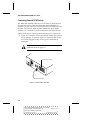
Follow these steps to connect external SCSI devices to Channel A:
1
Attach one connector of the external SCSI cable to the external
SCSI connector, as shown in Figure 5-7. External cable connectors can be plugged in only one way; pin-1 orientation is
automatic.
Caution: The external SCSI cables must meet the
guidelines listed on page 5-7.
External SCSI Connector
External SCSI Cable
Figure 5-7. External Cable to AHA-398x
5-10
AHA-3980/3980W/3985/3985W User’s Guide
Stock Number: 510810-00, Rev. D
Page: 5-10
Print Spec Number: 493479-00
Current Date: 3/1/99
ECN Date: 3/19/96
Installing the AHA-398x and the SCSI Drives
2
Attach the connector at the other end of the external cable to
either one of the SCSI connectors on the external SCSI device,
as shown in Figure 5-8.
External
SCSI Cable
External SCSI Device
Figure 5-8. External Cable to External SCSI Device
3
To connect other external SCSI devices, daisy chain each device
to the previous device until all external SCSI devices have been
connected, as shown in Figure 5-9.
External
SCSI Cables
Figure 5-9. Daisy Chaining External SCSI Devices
Caution: Be careful not to exceed the SCSI bus cable length
limitations. (The total bus length includes any cabling inside
the case of external devices.)
5-11
AHA-3980/3980W/3985/3985W User’s Guide
Stock Number: 510810-00, Rev. D
Page: 5-11
Print Spec Number: 493479-00
Current Date: 3/1/99
ECN Date: 3/19/96
AHA-3980/3980W/3985/3985W User’s Guide
Note: The computer in which the AHA-398x is installed can
share external SCSI devices with another computer. For
more information, see Sharing SCSI Devices with a Second
Computer on page 5-18.
Terminating the SCSI Bus
SCSI bus terminators must be either installed in, or enabled on, the
first and last SCSI devices on each AHA-398x channel; otherwise,
the devices will not operate properly. Terminators on all other
devices must be removed or disabled.
AHA-398x termination is enabled by default on all adapter channels.
At the other end of the SCSI bus, termination is usually provided by
the passthrough terminator (for the internal channels) or an external
SCSI device (if devices are attached to the external connector of
Channel A).
The following sections describe termination for each of the channels.
In reading the instructions, note that termination on most SCSI disk
drives, CD-ROM drives, and other SCSI devices is controlled by a
jumper or switch close to the SCSI connector. Some SCSI devices
have a resistor module that you insert or remove to control termination. See your device documentation for details.
Note: Some SCSI disk drives allow their terminators to
receive termination power from the SCSI bus instead of
from the drive’s power supply. AHA-398x RAID adapters
support this option, because they always supply termination power on the SCSI bus.
5-12
AHA-3980/3980W/3985/3985W User’s Guide
Stock Number: 510810-00, Rev. D
Page: 5-12
Print Spec Number: 493479-00
Current Date: 3/1/99
ECN Date: 3/19/96
Installing the AHA-398x and the SCSI Drives
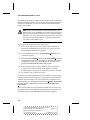
Terminating Channels B and C
Follow these steps to terminate the end devices on Channel B or C
(see Figure 5-10):
1
Leave the AHA-398x channel termination enabled (the
default).
2
Leave the passthrough terminator in place to terminate the
other end of the channel. (If you do not use the passthrough
terminator, you must install a terminator, or enable termination, on the last SCSI device attached to the channel.)
Caution: The passthrough terminator for the internal
SCSI channels helps ensure that termination is maintained constantly, which is important for disk arrays.
Without the passthrough terminator, an internal SCSI
device must provide termination. If that device is
removed because of failure, the bus is no longer terminated and the array may be compromised. We
strongly recommend using the terminator.
3
Remove the terminator, or disable termination, on all other
SCSI devices on the channel.
Channel
Termination
Enabled
Termination
Enabled
No
Termination
Figure 5-10. Termination on SCSI Channel B or C
5-13
AHA-3980/3980W/3985/3985W User’s Guide
Stock Number: 510810-00, Rev. D
Page: 5-13
Print Spec Number: 493479-00
Current Date: 3/1/99
ECN Date: 3/19/96
AHA-3980/3980W/3985/3985W User’s Guide
Terminating Channel A
The procedure for terminating Channel A depends on whether you
use one or both of the Channel A connectors. If you use only one of
the connectors (that is, the internal or the external connector, but not
both), the termination procedure is the same as that just described for
Channels B and C.
If you attach SCSI devices to both Channel A connectors, the steps
for terminating the channel are as follows (see Figure 5-11):
1
Leave the passthrough terminator in place to provide termination at the internal end of the bus.
2
Install a terminator, or enable termination, on the last SCSI
device attached to the external channel connector.
3
Disable AHA-398x termination for Channel A, following the
instructions in Changing the AHA-398x Settings on page 13-7.
4
Remove the terminators, or disable termination, on all other
SCSI devices attached to the internal and external connectors.
Channel
Termination
Disabled
Termination
Enabled
No
Termination
No
Termination
No
Termination
Termination
Enabled
Figure 5-11. Internal and External Devices on SCSI Channel A
5-14
AHA-3980/3980W/3985/3985W User’s Guide
Stock Number: 510810-00, Rev. D
Page: 5-14
Print Spec Number: 493479-00
Current Date: 3/1/99
ECN Date: 3/19/96
Installing the AHA-398x and the SCSI Drives
Setting SCSI IDs and Preparing a Boot Device
Each device on the SCSI bus, including the AHA-398x, must have a
unique SCSI ID. SCSI IDs uniquely define each SCSI device on the
bus and determine which device has priority when two or more
devices try to use the SCSI bus at the same time.
SCSI IDs on one channel do not interfere with IDs on another channel. IDs on one AHA-398x (or channel) do not interfere with those
on other installed adapters (or channels), as long as the adapters (or
channels) implement different SCSI buses.
Allowable SCSI IDs are 0 through 7 for devices on the AHA-3980/
3985. ID 7 has the highest priority, and ID 0 has the lowest. On the
AHA-3980W/3985W, allowable IDs are 0 through 15. The priority of
the remaining IDs, in descending order, is 6 to 0, then 15 to 8.
Setting SCSI IDs is a three-step process:
1
Determine which ID each device on the SCSI bus already has.
The default ID for Channels A, B, and C on the AHA-398x is
ID 7. To determine the IDs of disk drives and other SCSI
devices, read their documentation and examine their switch or
jumper settings.
2
Change the IDs (if needed) so that no two devices on the same
SCSI channel have the same ID. (Leave the channel IDs at the
default of SCSI ID 7.)
If a second AHA-398x or a different SCSI host adapter shares
the same SCSI bus, make sure its ID is not also 7. If necessary,
change either the channel ID or the adapter ID to 6. (See Host
Adapter (Channel) SCSI ID on page 13-2.)
3
If you plan to boot the computer from an array connected to
the AHA-398x adapter, assign SCSI ID 0 to one of the drives
you will use for that array and connect it to channel A. If you
plan to boot the computer from a stand-alone SCSI drive,
assign SCSI ID 0 to that drive. (See Chapter 6, Preparing a Boot
Device and Installing Drivers, for more information.)
If you are installing two or more AHA-398x adapters, be sure
the boot drive or array is connected to the adapter that is
scanned first. See Installing Multiple Adapters on page 5-17 for
more information.
5-15
AHA-3980/3980W/3985/3985W User’s Guide
Stock Number: 510810-00, Rev. D
Page: 5-15
Print Spec Number: 493479-00
Current Date: 3/1/99
ECN Date: 3/19/96
AHA-3980/3980W/3985/3985W User’s Guide
Connecting the SCSI Bus Activity Light
An LED light on the front panel of most computers indicates activity
on the disk. If you disconnect the cable from the motherboard and
attach it to the LED connector on the AHA-398x, the LED will light
whenever there is activity on any of the SCSI channels.
Note: You may not want to change the connection if your
computer system includes non-SCSI disk drives, because
the LED will no longer light when these drives are active.
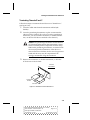
Follow these steps to connect the LED cable to the AHA-398x:
1
Refer to your computer’s documentation to locate the LED
cable, and unplug it from the connector on the system board.
2
Connect the LED cable to the SCSI activity LED connector on
the AHA-398x, as shown in Figure 5-12.
LED Cable
Pin 1
1
LED Connector J6
Figure 5-12. SCSI LED Connector
If the computer has a two-position LED cable, connect it to
pins 1 and 2 of the LED connector (pin 1 is the pin nearest the
edge of the board, as shown in Figure 5-12).
5-16
AHA-3980/3980W/3985/3985W User’s Guide
Stock Number: 510810-00, Rev. D
Page: 5-16
Print Spec Number: 493479-00
Current Date: 3/1/99
ECN Date: 3/19/96
Installing the AHA-398x and the SCSI Drives
Installing Multiple Adapters
You can install multiple AHA-398x RAID adapters in the same computer. You can also install an AHA-398x in computers that have
other PCI-, ISA-, or EISA-based host adapters. However, keep the
following considerations in mind:
■
All drives in an array must be connected to the same host
adapter. A single array cannot include drives from two or more
host adapters.
■
If you are booting from a SCSI disk drive or array, it must be
connected to the adapter that the computer scans first. Usually,
you need to determine by experimentation which PCI slot the
computer scans first and then make sure the adapter with the
boot device is installed in that slot. Some computers boot from
the device with the lowest PCI device number; others boot from
the device with the highest number. If the system does not boot
from the host adapter you want, move that host adapter to a different PCI slot and try again. Alternatively, you can disable the
BIOS on host adapters that are scanned before the desired boot
host adapter.
■
In systems with EISA- and ISA-based host adapters, the boot
host adapter must have the lowest BIOS base address. The system
BIOS automatically controls the AHA-398x base address (the user
has no control over the assigned address).
5-17
AHA-3980/3980W/3985/3985W User’s Guide
Stock Number: 510810-00, Rev. D
Page: 5-17
Print Spec Number: 493479-00
Current Date: 3/1/99
ECN Date: 3/19/96
AHA-3980/3980W/3985/3985W User’s Guide
Sharing SCSI Devices with a Second Computer
The AHA-398x adapter and an Adaptec host adapter in a second
computer can share the same SCSI devices without constantly
changing the cable configuration. In this arrangement, one of the
two computers can be powered at any one time, and that computer
can then access the devices. The host adapter in the unpowered
computer acts as a terminator at one end of the SCSI bus.
Note: The Adaptec host adapter in the second computer
need not be an AHA-398x, but it must be capable of active
termination when it is not powered. Most Adaptec host
adapters have this capability. Read the host adapter documentation if you are not sure.
To allow computers to share SCSI devices, follow these steps:
1
On the AHA-398x, install a jumper shunt on one or more of the
following jumpers, depending on the channel to be shared
(Figure 5-1 on page 5-2 and Figure 5-2 and on page 5-3 show
the jumper locations):
To connect a second host adapter in another computer to the
Channel A bus:
J2 for all AHA-398x adapters
To connect a second host adapter in another computer to the
Channel B bus:
J3 for AHA-3980/3985; J5 for AHA-3980W/3985W
To connect a second host adapter in another computer to the
Channel C bus:
J4 for AHA-3985; J7 for AHA-3985W
2
Install the AHA-398x as described in Installing the AHA-398x in
a PCI Slot on page 5-3.
5-18
AHA-3980/3980W/3985/3985W User’s Guide
Stock Number: 510810-00, Rev. D
Page: 5-18
Print Spec Number: 493479-00
Current Date: 3/1/99
ECN Date: 3/19/96
Installing the AHA-398x and the SCSI Drives
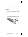
3
Connect the AHA-398x channel, the SCSI devices, and the host
adapter in the second computer as shown in Figure 5-13.
AHA-3980/3985
Computer 1
Other
SCSI Host
Adapter
Computer 2
Figure 5-13. SCSI Devices Shared by Two Computers
4
Assign different SCSI IDs to the AHA-398x channel and the
host adapter in the second computer (see Host Adapter (Channel) SCSI ID on page 13-2). IDs 6 and 7 are preferable, since
they have highest priority on the SCSI bus.
5
If necessary, change the IDs of the shared SCSI devices so no
devices have the same ID (see Setting SCSI IDs and Preparing a
Boot Device on page 5-15).
5-19
AHA-3980/3980W/3985/3985W User’s Guide
Stock Number: 510810-00, Rev. D
Page: 5-19
Print Spec Number: 493479-00
Current Date: 3/1/99
ECN Date: 3/19/96
AHA-3980/3980W/3985/3985W User’s Guide
Completing AHA-398x Installation
To complete installation of the AHA-398x RAID adapter, follow
these steps:
1
Replace and secure the cover of the computer case.
2
Reconnect the power cords to all external SCSI devices and the
computer.
3
Turn ON the power to all external SCSI devices. (You must turn
on the SCSI devices before you turn on the computer.)
4
Turn ON the computer.
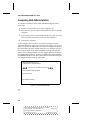
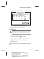
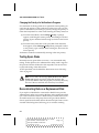
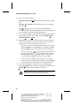
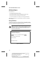
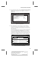
As the computer boots, look for an onscreen message from the
AHA-398x BIOS (see Figure 5-14). If it does not appear, your system
did not recognize the AHA-398x. Turn OFF the computer, make sure
the AHA-398x is properly seated in the PCI slot, and then turn ON
the computer again. If the AHA-398x BIOS message still does not
appear, your system probably does not support PCI-to-PCI bridges.
For additional information, read the troubleshooting information in
the 3980note.txt file on the AHA-3980/3985 Drivers and RAID Utilities diskette included with the AHA-398x.
Adaptec AHA-3980/3985 BIOS v1.50
(c) 1995 Adaptec, Inc. All Rights Reserved
Press <Ctrl> <A> for SCSISelect (TM) Utility!
AIC-7870/Sequencer Diagnostics Passed
[List of SCSI Devices]
.
.
.
BIOS Installed Successfully!
Figure 5-14. AHA-398x BIOS Message
❒
5-20
AHA-3980/3980W/3985/3985W User’s Guide
Stock Number: 510810-00, Rev. D
Page: 5-20
Print Spec Number: 493479-00
Current Date: 3/1/99
ECN Date: 3/19/96
▼ ▼ ▼ ▼
6
Preparing a Boot Device and
Installing Drivers
This chapter explains how to prepare a boot device connected to
your AHA-398x adapter and how to install the DOS and NetWare
drivers you will need to load software and to use arrays.
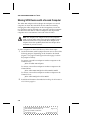
The boot device can be an array or a stand-alone disk drive. We recommend that you boot your computer from an array, because you
can take advantage of the data redundancy provided by most levels
of RAID. (See Chapter 2, Array Basics, to learn about the features of
different RAID levels.) If you boot from a stand-alone disk drive,
you can use a SCSI drive connected to the AHA-398x adapter or a
non-SCSI drive (usually an IDE or EIDE drive).
If a non-SCSI drive is installed in your computer, the computer will
always attempt to boot from that drive and will never boot from a
SCSI drive or array.
Getting Ready to Prepare a Boot Device
Follow these steps, regardless of whether you plan to boot from an
array or from a stand-alone disk drive. We assume here that
MS-DOS and NetWare are not already installed on the computer
with the AHA-398x adapter. You will need to have access to a second computer.
1
2
Complete the hardware installation steps in Chapter 5.
Be sure the intended boot drive—or at least one drive that will
be in the boot array—is connected to Channel A of the
AHA-398x.
6-1
AHA-3980/3980W/3985/3985W User’s Guide
Stock Number: 510810-00, Rev. D
Page: 6-1
Print Spec Number: 493479-00
Current Date: 3/1/99
ECN Date: 3/19/96
AHA-3980/3980W/3985/3985W User’s Guide
If your computer has two or more PCI adapters, the boot
device must be connected to the adapter in the PCI slot that is
scanned first. See page 5-17 for more information.
3
Be sure the boot drive (or a drive that will be part of the boot
array) has been assigned SCSI ID 0 on channel A.
4
Obtain a licensed copy of MS-DOS, and boot the computer
from Disk 1 - the Setup disk.
5
Press F3 twice to exit from the MS-DOS Setup program, then
remove the MS-DOS disk from the disk drive.
Do not turn the computer off.
6
Go to a computer on which DOS 5.0 or above (preferably
DOS 6.0 or above) is already installed, type format a: /s at the
DOS prompt, and press Enter.
7
Insert a blank floppy diskette in the A drive of this computer
and press Enter again. This command makes the diskette
bootable.
8
When the formatting is completed, copy the fdisk.exe and
format.com files from the computer’s DOS directory to the
newly formatted floppy diskette.
9
Copy the files on the Adaptec Initial Array Configuration Utility diskette to the newly formatted diskette that has the
fdisk.exe and format.com files.
Put the original Adaptec Initial Array Configuration Utility
diskette in a safe place.
10 Remove the new diskette from the disk drive of the second
computer.
If you plan to boot from an array, continue with the next section, Creating an Array with the Initial Array Configuration Utility.
If you plan to boot from a stand-alone disk drive, skip to Formatting
and Partitioning the Array or Drive on page 6-7.
6-2
AHA-3980/3980W/3985/3985W User’s Guide
Stock Number: 510810-00, Rev. D
Page: 6-2
Print Spec Number: 493479-00
Current Date: 3/1/99
ECN Date: 3/19/96
Preparing a Boot Device and Installing Drivers
Creating an Array with the Initial Array
Configuration Utility
You can also create arrays with the Administrator Utility described
in Part 3 of this document. However, if you want to install NetWare
on the array, you must create it with the Initial Array Configuration
Utility. This section describes only the Initial Array Configuration
Utility options that are required to create an array. For information
about other options, see Other Initial Array Configuration Utility
Options on page 6-14.
1
Insert the new diskette in drive A of the computer with the
AHA-398x adapter.
2
Type a:arconfig at the DOS prompt and press Enter to start the
Initial Array Configuration Utility.
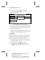
If only one AHA-398x RAID adapter is installed, the Main
Menu shown in Figure 6-15 appears. If there are two or more
AHA-398x adapters, an intermediate menu appears from
which you select the adapter for which you want to create the
array.
Adaptec Initial Array Configuration Utility
Array Menu
Display Arrays
Add New Array
Delete Array
Replace Array Drive
Initialize Array
Figure 6-15. Initial Array Configuration Utility Main Menu
3
When the main menu appears, select Add New Array. The
Select Array Menu appears.
To select Initial Array Configuration Utility menu options,
type the hot key—the letter in the option that appears in a dif6-3
AHA-3980/3980W/3985/3985W User’s Guide
Stock Number: 510810-00, Rev. D
Page: 6-3
Print Spec Number: 493479-00
Current Date: 3/1/99
ECN Date: 3/19/96
AHA-3980/3980W/3985/3985W User’s Guide
ferent color. You can also press the ↑ and ↓ keys until the
option is highlighted and then press Enter. If you have a
monochrome monitor and the highlight bar is not visible, press
Ctrl-B to change to monochrome mode.
4
Press Enter to define Array #1 (assuming that you have not yet
defined any other arrays).
The Select Array Type menu appears on the left of the screen,
as shown in Figure 6-16.
Adaptec Initial Array Configuration Utility
Select Array Type
RAID0
Mirrored
RAID5
Select Array
Array #1
Array #2
Array #3
Array #4
Up/Dn: MoveUp/Down
Enter: Select Array
Esc:
Previous Menu
Figure 6-16. Selecting an Array and an Array Type
5
Select an array type for the new array. (See Chapter 2, Array
Basics, for an explanation of the various RAID levels and array
types.)
If you select RAID 5 or RAID 0, a screen appears asking you if
you want to make the array convertible between RAID 5 and
RAID 0. Read the onscreen explanation and select y or n.
6
When a prompt appears asking how many drives the array
will contain, type the number of drives (excluding spares) and
press Enter.
The screen lists the number of drives available for assignment
on all the channels of this adapter. It also lists the maximum
and minimum number of drives allowed for each kind of array.
6-4
AHA-3980/3980W/3985/3985W User’s Guide
Stock Number: 510810-00, Rev. D
Page: 6-4
Print Spec Number: 493479-00
Current Date: 3/1/99
ECN Date: 3/19/96
Preparing a Boot Device and Installing Drivers
Note: A spare is a disk drive associated with an array
that will be used automatically as a replacement if one
of the active drives in the array fails.
7
When the next screen appears, as shown in Figure 6-17, press
Tab to highlight a channel. When the drives on the highlighted
channel appear in the SCSI IDs on Channel menu, select the
drives for the array. (Press the ↑ and ↓ keys until the drive
name is highlighted, then press Ins or Enter.) The names of
selected drives appear to the right, in the Adaptec Array # box.
Adaptec Initial Array Configuration Utility
AHA-3980
Bus #1
Channel A
Channel B
Array #1
SCSI IDs on Channel
#0
#1
#2
#3
QUANTUM
CONNER
CONNER
CONNER
LPS34
CFA540
CFA540
CFA540
335MB
537MB
537MB
537MB
Type=Mirrored
Drive Channel ID
Tab = Select channel
Up/Dn Arrow = Select drive
Ins = Install drive
Del = Deselect drive
Figure 6-17. Selecting Drives for an Array
To select drives on a different host adapter channel, press Tab
to select another channel and then select the drives from the
SCSI IDs on Channel menu. To deselect the drive you most
recently added, press Del.
When you have selected the number of drives you specified in
step 6, the next screen appears automatically.
8
If the array is mirrored or RAID 5 and there are still one or
more unassigned drives, a prompt appears asking whether
you want to define spare drives for the array.
6-5
AHA-3980/3980W/3985/3985W User’s Guide
Stock Number: 510810-00, Rev. D
Page: 6-5
Print Spec Number: 493479-00
Current Date: 3/1/99
ECN Date: 3/19/96
AHA-3980/3980W/3985/3985W User’s Guide
Note: A spare must have at least the capacity of the
smallest drive in the array.
If you do not want a spare: Type n and continue with step 9.
To select a spare: Follow these steps:
a At the prompt, type y.
b If more than one drive is available, a second prompt
appears, asking how many spares the array will have. Type
1 or 2 and press Enter.
c To select each spare, follow the directions in step 7.
9
When the Select Format Mode menu appears, select Initialize
Array to Zero, the recommended mode.
Select Low-Level Format only if the drives were previously
formatted on another system or if you think they may have
surface defects. Low-level formatting can take a long time for
large disk drives. (See Initializing an Array on page 6-16 for
more information.)
Caution: If the drives contain data, all the data will be
lost when you initialize or format the array.
10 When the menu of block sizes appears, select a block size. (This
menu does not appear if the array is a mirrored array with only
two drives). The recommended size is 16 KBytes.
11 Confirm that you want to format the array by typing y at the
prompt. You will see percentage complete information on the
screen as the array is formatted.
Note: You cannot cancel an Initialize Array to Zero or
low-level format once it has started.
12 When you see the message Initialization of Array #N is complete, press any key to return to the Main Menu.
6-6
AHA-3980/3980W/3985/3985W User’s Guide
Stock Number: 510810-00, Rev. D
Page: 6-6
Print Spec Number: 493479-00
Current Date: 3/1/99
ECN Date: 3/19/96
Preparing a Boot Device and Installing Drivers
13 Press Esc and, with the newly-created diskette still in the drive,
reboot the computer when you see the prompt.
Formatting and Partitioning the Array or Drive
Follow these steps regardless of whether you are creating a boot
drive or a boot array.
1
Insert the diskette onto which you copied the Initial Array
Configuration Utility into the A drive of the computer with the
AHA-398x adapter. Then reboot the computer. (This has
already been done if you just created an array.)
2
When the DOS prompt appears, type a:fdisk and press Enter.
The FDISK Options menu appears. Above the list of options is
the message Current fixed disk drive: 1.
3
If you are sure the disk drive noted in the message is the one
you want to partition, continue with the next step. Otherwise,
select Change current fixed disk drive (this option does not
appear if fdisk found only one drive); from the list of drives
that appears, select the drive you want to partition.
4
5
6
Select Create DOS partition or Logical DOS Drive.
7
When prompted, enter a partition size of about 20 MBytes.
This will allow sufficient space for all DOS files, leaving the
rest of the array (or disk) for a NetWare partition.
8
9
Press Esc until the FDISK Options menu reappears.
Select Create Primary Partition.
When prompted whether you want the maximum partition
size, type n (no).
Select Set active partition, then follow any prompts that
appear.
10 When finished, exit fdisk by pressing Esc. (Be sure the diskette
is still in the drive.) The system reboots.
11 Type a:format c: /s and press Enter. This formats the array (or
disk) and makes it bootable.
12 When the formatting operation is complete, remove the diskette from the drive and reboot the system. It will now boot
from the hard drive or array.
6-7
AHA-3980/3980W/3985/3985W User’s Guide
Stock Number: 510810-00, Rev. D
Page: 6-7
Print Spec Number: 493479-00
Current Date: 3/1/99
ECN Date: 3/19/96
AHA-3980/3980W/3985/3985W User’s Guide
At this point you have installed enough DOS to enable you to install
NetWare. If you want to fully install DOS, complete these steps:
1
Remove the copied Initial Array Configuration Utility diskette
from the drive and insert Disk 1 of the licensed copy of DOS.
2
3
Reboot the computer.
Proceed with the DOS Setup program. Ignore the message
about DOS already being installed. When you are finished, the
full version of DOS will be installed on the DOS partition you
created earlier.
Copying Drivers
The AHA-398x includes a diskette with drivers for NetWare 3.11,
3.12, and 4.xx. DOS CD-ROM drivers are included so you can install
NetWare from a CD-ROM drive. Follow these steps to copy the drivers to your hard disk drive or array:
1
Insert the AHA-3980/3985 Drivers and RAID Utilities diskette
in the A drive.
2
3
At the DOS prompt, type a:install, and press Enter.
When the Adaptec Array Driver Copy Utility menu appears,
as shown in Figure 6-18, select one of the NetWare options,
depending on which version of NetWare you are installing on
the computer.
Adaptec Array Driver Copy Utility
Install Software Drivers
CD-ROM Drivers
Netware 3.xx Drivers
Netware 4.xx Drivers
Installs CD-ROM drivers in user-specified directory
Figure 6-18. The Install Software Drivers Menu
6-8
AHA-3980/3980W/3985/3985W User’s Guide
Stock Number: 510810-00, Rev. D
Page: 6-8
Print Spec Number: 493479-00
Current Date: 3/1/99
ECN Date: 3/19/96
Preparing a Boot Device and Installing Drivers
4
When you are prompted, press Enter to accept the suggested
default directory where the NetWare drivers will be copied.
This will be either \server.312 or \nwserver.
5
If a CD-ROM drive is connected to the AHA-398x and you will
use it to install NetWare from a CD disc, return to the Main
Menu and select CD-ROM drivers. Otherwise, skip to step 7.
6
When you are prompted, press Enter to accept the suggested
default directory (\scsi) where the CD-ROM drivers will be
copied. (See Chapter 14, Using a CD-ROM Drive, to learn more
about using a CD-ROM drive under DOS and Windows.)
7
When the drivers have been copied, press Esc to exit from the
Adaptec Array Driver Copy Utility.
8
Copy the config.sys and autoexec.bat files from the \dos directory of the AHA-3980/3985 Drivers and RAID Utilities diskette to the root directory of your new boot array or boot drive.
If the drive already has config.sys and autoexec.bat files, you
can manually add the lines for the CD-ROM drivers. See the
3980dos.txt file on the AHA-3980/3985 Drivers and RAID
Utilities diskette.
9
Remove the AHA-3980/3985 Drivers and RAID Utilities diskette from the disk drive and reboot the computer.
Installing NetWare on a New Server
NetWare 3.11
Version 3.11 of NetWare is installed from floppy disks. Refer to the
NetWare documentation for instructions on installing this version of
NetWare.
NetWare 3.12
1
Use SCSISelect to determine the number of the PCI bus where
the AHA-398x is installed:
a Boot the computer and press Ctrl-A when you see
Press <Ctrl><A> for SCSISelect (TM) Utility!
6-9
AHA-3980/3980W/3985/3985W User’s Guide
Stock Number: 510810-00, Rev. D
Page: 6-9
Print Spec Number: 493479-00
Current Date: 3/1/99
ECN Date: 3/19/96
AHA-3980/3980W/3985/3985W User’s Guide
b Look at the first screen that appears. The screen lists the
PCI bus number and channels for each AHA-398x. The PCI
bus number precedes each channel letter. The entry 01:A
(Channel A on PCI bus 1), for example, indicates the
AHA-398x is on PCI bus 1.
c When finished, press Esc to exit SCSISelect.
2
Insert the NetWare 3.12 installation disc in the computer’s
CD-ROM drive.
3
Change to the directory that contains the NetWare file
install.bat. The directory is similar to d:\netware.40\english
(assuming you are installing from a CD-ROM drive designated
drive D).
4
5
6
7
8
Type install and press Enter. A note to Ethernet users appears.
Press any key to continue.
Select Install new NetWare 3.12.
Select Retain current disk partitions.
Follow the instructions in the NetWare documentation to complete the installation. The installation program prompts you to
enter a server name, an IPX number, and a destination directory for the server boot files. After the installation program
copies the server boot files to that directory, you are further
prompted to choose the country code, the file name format,
and commands for the startup.ncf and autoexec.ncf files.
During installation, you can press F1 to obtain onscreen help. If
you need additional help, refer to the NetWare documentation.
9
Add the following lines to the startup.ncf file, located in the
directory containing server.exe (the lines can be anywhere in
the file):
load aha3980 bus_num=x
load ardrvr
where x is the PCI bus number you determined in step 1.
When aha3980.dsk loads, it automatically loads aspitran.dsk;
therefore, you need not include a separate load line for
aspitran.dsk. For startup.ncf to properly execute, aspitran.dsk
must be in the same directory as aha3980.dsk.
6-10
AHA-3980/3980W/3985/3985W User’s Guide
Stock Number: 510810-00, Rev. D
Page: 6-10
Print Spec Number: 493479-00
Current Date: 3/1/99
ECN Date: 3/19/96
Preparing a Boot Device and Installing Drivers
Note: The NetWare Create Startup option does not
work correctly with PCI devices. If you use it, you will
find four load aha3980 lines that need to be deleted.
10 If, during the NetWare installation, you did not modify the
autoexec.bat file to include the path for server.exe, change to
the directory containing server.exe. Usually, the directory is
c:\server.312.
11 At the DOS prompt, type server and press Enter. The server
loads.
12 At the server prompt (:), type load install and press Enter. Create the NetWare partition, the sys volume, and other volumes,
following the instructions in the NetWare documentation.
NetWare 4.xx
1
Determine the number of the PCI bus where the AHA-3980/
3985 resides. To do so, you can use SCSISelect:
a Boot the computer and press Ctrl-A when you see
Press <Ctrl><A> for SCSISelect (TM) Utility!
b Look at the first screen that appears. The screen lists the
PCI bus number and channels for each AHA-398x. The PCI
bus number precedes each channel letter. The entry 01:A
(Channel A on PCI bus 1), for example, indicates the
AHA-398x is on PCI bus 1.
c When finished, press Esc to exit SCSISelect.
2
Insert the NetWare installation disc in the computer’s
CD-ROM drive.
3
Change to the root directory of the installation disk containing
the NetWare installation batch file (d:\install.bat, assuming you
are installing from a CD-ROM drive designated as drive D).
4
5
Type install and press Enter.
Follow the instructions in the NetWare documentation to continue the installation on a single machine. During installation,
you can press F1 to obtain online help.
6-11
AHA-3980/3980W/3985/3985W User’s Guide
Stock Number: 510810-00, Rev. D
Page: 6-11
Print Spec Number: 493479-00
Current Date: 3/1/99
ECN Date: 3/19/96
AHA-3980/3980W/3985/3985W User’s Guide
When a screen similar to the one in Figure 6-19 appears, continue with the next step.
NetWare Server Installation v4.x
NetWare Loadable Module
Load Disk Driver
Choose a disk driver that corresponds to the disk controller hardware in the server.
Repeat this step for additional drivers.
Select a disk driver
AHA3980.DSK Adaptec AHA-3980/3985 ASPI Manager & SCSI Disk Module
Loaded Drivers
Load a disk driver listed
Load disk driver not listed
Unload a disk driver
Scroll help window
Help <F1> Previous Screen
<Enter>
<Ins>
<Del>
<F5> (up) <F6> (dn) Change lists <F2>
<Esc>
Abort INSTALL <Alt> <F10>
Figure 6-19. Selecting AHA3980.DSK
6
7
8
Press Insert to load a disk driver not installed.
Press F3, type c:\nwserver, and press Enter. A list of drivers
appears.
Highlight aha3980.dsk and press Enter. Repeat this for each
adapter that is installed.
The installation program copies the necessary files to the directory containing the server.exe file.
Note: Do not select ASPITRAN.DSK; that is done
automatically.
9 Choose Yes to select an additional disk driver.
10 Highlight ardrvr.dsk and press Enter.
If you wish to install other adapter drivers, specify them here. (If
all adapters are the same model, you must load the same driver
again for each adapter.)
11 Continue the installation using the instructions for your network card.
6-12
AHA-3980/3980W/3985/3985W User’s Guide
Stock Number: 510810-00, Rev. D
Page: 6-12
Print Spec Number: 493479-00
Current Date: 3/1/99
ECN Date: 3/19/96
Preparing a Boot Device and Installing Drivers
After you finish specifying the drivers, a summary screen
shows the drivers that the installation program will load.
12 The installation program attempts to load aha3980.dsk but
cannot, because no PCI bus number has been specified yet. You
must add command line parameters to aha3980.dsk to specify
the bus number. The ardrvr.dsk does not require any changes.
To add command line parameters, follow these steps:
a Press F3.
b Edit the command line information for c:\aha3980.dsk and
add the following command:
load aha3980 bus_num=x
where x is the PCI bus number you determined in step 1.
If you are installing additional AHA-398x RAID adapters,
be sure to enter different bus numbers for each RAID
adapter.
Note: Press <Alt>+<Esc> to switch between the console screen and the installation program screen. The
console screen displays a message indicating whether
the driver loaded successfully. If an error message
appears, see Appendix B, Software Error Messages.
13 Continue loading each driver you specified earlier.
14 Continue with the NetWare installation by following the procedures in the NetWare documentation. When prompted, select
Retain current disk partitions.
15 When the installation program finishes, use an ASCII text editor to edit the startup.ncf file as follows:
a Delete duplicate load lines for aha3980.dsk until there is
only one load line for each AHA-398x. If necessary, insert
one load line for each AHA-398x using the format shown
in step 12b. (You can add the lines anywhere in the file.)
6-13
AHA-3980/3980W/3985/3985W User’s Guide
Stock Number: 510810-00, Rev. D
Page: 6-13
Print Spec Number: 493479-00
Current Date: 3/1/99
ECN Date: 3/19/96
AHA-3980/3980W/3985/3985W User’s Guide
b Check to make sure there is a load line for ardrvr. Your
startup.ncf should now load aha3980.dsk for every
installed AHA-398x adapter, followed by a single ardrvr
load line.
Note: The aha3980.dsk driver supports the NetWare
tape backup utility, sbackup.nlm. Use aha3980.dsk,
not the adaptec.nlm driver provided by NetWare,
when running this utility. Adaptec’s aha3980.dsk
driver takes advantage of ASPI features bypassed by
adaptec.nlm.
Other Initial Array Configuration Utility Options
Creating an Array with the Initial Array Configuration Utility, which
begins on page 6-3, describes how to use the Initial Array Configuration Utility to create an array that you can use for a boot device. Normally, this is the only task for which you will use this utility. Then
you can create and manage other arrays with the Administrator
Utility after you install NetWare.
This section describes the other Initial Array Configuration Utility
menu options, in case you need to use them.
Displaying Array Information
Follow these steps to display information about an array that has
already been defined on your system:
1
2
Select Display Arrays from the Main Menu.
When the Array Menu appears, move the highlight to the
array you want to view and press Enter.
6-14
AHA-3980/3980W/3985/3985W User’s Guide
Stock Number: 510810-00, Rev. D
Page: 6-14
Print Spec Number: 493479-00
Current Date: 3/1/99
ECN Date: 3/19/96
Preparing a Boot Device and Installing Drivers
3
View the information that appears on the screen. A sample
screen is shown in Figure 6-20.
Adaptec Initial Array Configuration Utility
Configuration for Array #1
Type = RAID5 Drives = 4 Boot Array = Yes Array Size (MB) = 8158
Array Status = Initialized
Data Block Size (KB) =16
Capacity
Status
Channel
SCSI ID
Member
2040 MB
UP
A
1
0
2040 MB
UP
A
3
1
2040 MB
UP
B
4
2
2040 MB
UP
B
5
3
Press any key to continue
Figure 6-20. Sample Array Configuration Screen
4
Press any key to return to the Main Menu.
Deleting an Array
Caution: Before you delete an array, back up any data you
want to keep. When you delete the array, all array data is
lost!
To delete an array, follow these steps:
1
2
From the Main Menu, select Delete an Array.
3
4
Type y to delete the array, or n to cancel the operation.
When the menu of arrays appears, select the array you want to
delete. A prompt asks you to confirm the deletion.
Restart the system.
The drives that were formerly part of the array can now be used as
standard NetWare drives, or they can be redefined as part of another
array.
6-15
AHA-3980/3980W/3985/3985W User’s Guide
Stock Number: 510810-00, Rev. D
Page: 6-15
Print Spec Number: 493479-00
Current Date: 3/1/99
ECN Date: 3/19/96
AHA-3980/3980W/3985/3985W User’s Guide
Replacing an Array Drive
Follow these steps to replace a down drive in an array:
1
2
From the Main Menu, select Replace Array Drive.
3
When the next screen appears, press Tab to highlight the channel of the drive you want to replace. When the drives on the
highlighted channel appear in the SCSI IDs on Channel menu,
select the drive you want to replace.
When the menu of arrays appears, select the array that has the
drive you want to replace.
Note: You cannot replace the drive if it is currently up,
since this would not make sense. You should only
attempt to replace a drive if it is down.
4
When the menu of channels appears, press Tab to select the
channel that has the new drive you want to add to the array.
5
Select the drive on this channel that you want to add to the
array.
6
When the message Member of Array #N replaced appears,
press any key to return to the Main Menu.
Initializing an Array
When you add a new array, you are automatically prompted to initialize (format) it. If necessary, you can also select the Initialize
Array option separately from the Main Menu, perhaps to reinitialize
an array that has become corrupted.
Here is some additional information on the two initialization
methods:
■
Initialize Array to Zero: (Recommended method) Fills the
array with zeroes. This option is faster than a low-level format,
but it does not verify the integrity of the disks. You can abort an
initialization while it is underway; however, you must later
complete the initialization.
6-16
AHA-3980/3980W/3985/3985W User’s Guide
Stock Number: 510810-00, Rev. D
Page: 6-16
Print Spec Number: 493479-00
Current Date: 3/1/99
ECN Date: 3/19/96
Preparing a Boot Device and Installing Drivers
■
Low-level Format: Performs a low-level SCSI format. This
writes a consistent pattern to the disks and checks the disks for
defects. Then it fills the array with zeroes. Low-level
formatting can take a long time (the speed varies by drive
model), and you cannot abort it once it has started.
Follow these steps to initialize an array:
1
2
Select Initialize Array from the Array Menu.
When the Select Array menu appears, select the array you
want to initialize.
Note: You are not allowed to initialize the array if one
or more of the array drives is missing or down.
3
When the Select Format Mode menu appears, select Initialize
Array to Zero or Low-Level Format.
Caution: Formatting or initializing an array erases all
data on the array and cannot be canceled once it has
started. If the array contains data you want to keep, be
sure to back it up first!
4
When the menu of block sizes appears, select a block size. (This
menu does not appear if the array is a mirrored array with only
two drives).
The allowable block sizes are 8, 16 (the default), 32, or
64 KBytes. The default size gives the best overall performance.
If you will perform mostly sequential access on the array, you
may achieve better performance if you use larger stripe sizes
and larger NetWare volume block sizes.
5
When prompted, confirm that you want to format the array by
typing y (yes). The initialization process begins.
6
When you see the message Initialization of Array #N is complete, press any key to return to the Array Menu.
❒
6-17
AHA-3980/3980W/3985/3985W User’s Guide
Stock Number: 510810-00, Rev. D
Page: 6-17
Print Spec Number: 493479-00
Current Date: 3/1/99
ECN Date: 3/19/96
AHA-3980/3980W/3985/3985W User’s Guide
Stock Number: 510810-00, Rev. D
Page: 6-18
Print Spec Number: 493479-00
Current Date: 3/1/99
ECN Date: 3/19/96
▼ ▼ ▼ ▼
Part 3
Managing Arrays
AHA-3980/3980W/3985/3985W User’s Guide
Stock Number: 510810-00, Rev. D
Page: Part 3-xix
Print Spec Number: 493479-00
Current Date: 3/1/99
ECN Date: 3/19/96
AHA-3980/3980W/3985/3985W User’s Guide
Stock Number: 510810-00, Rev. D
Page: Part 3-xx
Print Spec Number: 493479-00
Current Date: 3/1/99
ECN Date: 3/19/96
▼ ▼ ▼ ▼
7
Understanding the
Administrator Utility
You use the Administrator utility to create and manage arrays while
running NetWare. The Administrator utility lets you
■
Create up to four arrays per server
■
Monitor array performance
■
Perform array tasks, such as verifying array integrity, testing
spare disks, and re-creating data on replacement disks
■
Change array configuration and delete arrays
This chapter explains how to start and exit the Administrator Utility
and summarizes the options on the Main and System menus. Following chapters provide detailed instructions for using all options.
Note: Before you start the Administrator utility, make sure
the aha3980.dsk driver is installed. See Installing NetWare on a
New Server on page 6-9 for more information.
7-1
AHA-3980/3980W/3985/3985W User’s Guide
Stock Number: 510810-00, Rev. D
Page: 7-1
Print Spec Number: 493479-00
Current Date: 3/1/99
ECN Date: 3/19/96
AHA-3980/3980W/3985/3985W User’s Guide
Starting the Administrator Utility
To start the Administrator utility, follow these steps:
1
2
If the server is not running, start it.
At the server prompt, enter one of the following commands:
a Enter load c:aruadmin if this is the first time you have run
the Administrator Utility.
If no previously defined arrays are detected, the utility
starts in setup mode. If one or more arrays have already
been defined and if arumon is not in autoexec.ncf, arumon
is added to the autoexec.ncf file and the utility suite is
automatically copied over from the server.exe directory.
b Enter load aruadmin if this is not the first time you have run
the Administrator Utility.
Exiting the Administrator Utility
To exit the Administrator utility, follow these steps:
1
Press Esc until the following prompt appears:
Do you want to exit the Administrator? (y|n)
2
Type y. You return to the server prompt.
7-2
AHA-3980/3980W/3985/3985W User’s Guide
Stock Number: 510810-00, Rev. D
Page: 7-2
Print Spec Number: 493479-00
Current Date: 3/1/99
ECN Date: 3/19/96
Understanding the Administrator Utility
The Main and System Menus
The Administrator utility has two primary menus: the Main Menu,
shown in Figure 7-21, and the System Menu, shown in Figure 7-22. If
your system has only one array, the Main Menu appears when you
start the Administrator utility. If your system has multiple arrays,
the System Menu appears when you start the utility.
Main Menu For Array #1
Display Array Status
Verify Functions
Reconstruct Functions
Format/Initialize Array
Convert RAID Level
Change Array Configuration
Scheduler Functions
Reactivate Off-line Array
Reactivate Spare
Hardware Functions
Install Utility Suite
Figure 7-21. Administrator Utility Main Menu
System Menu
Select Target Array
Display Array Status
Change Array Configuration
Install Utility Suite
Figure 7-22. Administrator Utility System Menu
Main Menu
The Main Menu lists the tasks you can perform for an individual
array:
■
Display Array Status: Display information on the array and on
disks included in the array. For details, see Obtaining Array
Information on page 8-1.
■
Verify Functions: Verify the data on the array (RAID 5 and mirrored arrays only). For details, see Verifying Arrays on page 9-1.
■
Reconstruct Functions: Re-create data on a replacement disk.
For details, see Reconstructing Data on a Replacement Disk on
page 9-4.
7-3
AHA-3980/3980W/3985/3985W User’s Guide
Stock Number: 510810-00, Rev. D
Page: 7-3
Print Spec Number: 493479-00
Current Date: 3/1/99
ECN Date: 3/19/96
AHA-3980/3980W/3985/3985W User’s Guide
■
Format/Initialize Array: Format or initialize an array for a
specified RAID level. For details, see Chapter 11, Initializing
Arrays.
■
Convert RAID Level: Switch between RAID 0 CVT and
RAID 5 CVT formats. For information on why you might do
this, see RAID 0 CVT and RAID 5 CVT on page 2-3. For instructions, see Converting between RAID 0 CVT and RAID 5 CVT on
page 10-7.
■
Change Array Configuration: Add an array (see Adding an
Array on page 10-1). Change an existing array (see Modifying
an Array on page 10-5). Delete an array (see Deleting Arrays
and Deinstalling NLMs on page 10-10). Delete a spare (see
Deleting a Spare Disk on page 10-7). Change who receives
broadcast messages (see Determining Who Receives Messages on
page 8-5). Change the frequency at which messages repeat (see
Setting the Repeat Interval for Error Messages on page 8-7). Install
the Adaptec array utilities (see Installing the Array Utilities in
the sys:system Directory on page 10-11).
■
Scheduler Functions: Schedule the Reconstruct, Verify, and
Spare Test functions to run automatically at a specified time or
regular interval. For details, see Scheduling Tasks on page 9-7.
■
Reactivate Off-line Array: Restore to service an array that is offline. For details, see Reactivating an Off-line Array on page 9-7.
■
Reactivate Spare: This menu option is grayed out and is not
selectable.
■
Hardware Functions: Perform the following hardware-related
tasks: Display the array that uses a specific drive; blink the
drive light for a drive (helps you find a specific drive); and suspend activity on the host adapter channels used in an array
(for drive boxes that require you to suspend SCSI bus activity
before removing a drive). For details, see Using the Hardware
Functions on page 9-9.
■
Install Utility Suite: Install the Adaptec array utilities in the
NetWare sys:system directory from the netware directory on
C: (see Installing the Array Utilities in the sys:system Directory on
page 10-11). This option is also available from the Change
Array Configuration Menu. The array utilities are normally
installed automatically.
7-4
AHA-3980/3980W/3985/3985W User’s Guide
Stock Number: 510810-00, Rev. D
Page: 7-4
Print Spec Number: 493479-00
Current Date: 3/1/99
ECN Date: 3/19/96
Understanding the Administrator Utility
System Menu
If a server has more than one array, the System Menu appears when
you start the Administrator utility. If you select Select Target Array,
the first option, a list of array names appears in a separate menu. If
you select an array name, the Main Menu for that array appears, as
shown in Figure 7-21. You select options in the Main Menu to perform tasks related to that array.
The System Menu also has the Display Array Status and Change
Array Configuration options. Change Array Configuration has the
same function as the Change Array Configuration option in the
Main Menu. Display Array Status allows you to view the status of
all arrays on the system, not just a selected array.
The entries in the Array Status window are color-coded to indicate
the status of the array. Green means the array is operational, red
means the array is off-line, and yellow means one of the array drives
is down.
Selecting Menu Options
Option names in most menus include a hot key—a light blue character in color monitors, and a gray character in monochrome monitors.
To select one of these options, just type the hot key. In the Main
Menu in Figure 7-21, for example, the Display Array Status option
has the hot key D; to select this option, type d. In this document, hot
keys are indicated by an underlined character in the option name.
You can also select a menu option by pressing the ↑ and ↓ keys to
highlight the option and then pressing Enter. If an option does not
have a hot key, use this method to select it.
Note: If you have a monochrome monitor and the highlight
bar is not visible, press Ctrl-B to change to monochrome
mode.
7-5
AHA-3980/3980W/3985/3985W User’s Guide
Stock Number: 510810-00, Rev. D
Page: 7-5
Print Spec Number: 493479-00
Current Date: 3/1/99
ECN Date: 3/19/96
AHA-3980/3980W/3985/3985W User’s Guide
Grayed Menu Options
Grayed menu options are not selectable, usually because they do not
apply to the chosen array. If an array has no failed drives, for example, the Reconstruct Functions option on the Main Menu is grayed,
because no drives need to be reconstructed. Similarly, the Convert
RAID Level option is always grayed for a mirrored array, because
you cannot convert a mirrored array to another format.
Getting Help
You can display Help windows for most menus by pressing F1. As
you highlight menu options, the Help windows automatically
change to provide information about the highlighted option. To
clear the Help windows, press F1 again.
❒
7-6
AHA-3980/3980W/3985/3985W User’s Guide
Stock Number: 510810-00, Rev. D
Page: 7-6
Print Spec Number: 493479-00
Current Date: 3/1/99
ECN Date: 3/19/96
▼ ▼ ▼ ▼
8
Monitoring Array
Performance
The Administrator utility monitors the performance of the arrays
and compiles statistics—for example, number of reads and writes
and number of bad sectors reassigned—and lets you view this information at the server console. If you have the Adaptec CI/O software,
you can also view the statistics at a remote workstation.
The Administrator utility also monitors arrays for problems, such as
failed drives. If it detects a problem, it issues an alert. Use the Administrator utility to determine who receives the alerts and how often the
alerts repeat onscreen. If the Adaptec CI/O software is installed at a
remote workstation, the alerts appear there also.
Obtaining Array Information
You can display the following types of information for any array on a
server:
■
An overview of the logical array characteristics (see Figure 823)
■
An overview of physical array characteristics and any utilities
running on the array (see Figure 8-24)
■
Performance statistics for an array and its drives
■
A list of all NetWare volumes on the selected array
8-1
AHA-3980/3980W/3985/3985W User’s Guide
Stock Number: 510810-00, Rev. D
Page: 8-1
Print Spec Number: 493479-00
Current Date: 3/1/99
ECN Date: 3/19/96
AHA-3980/3980W/3985/3985W User’s Guide
Overview for Array #1
Array Model = AHA-3980 Two Channel RAID on PCI Bus #1
Creation date = Tue Oct 4 11:11:57 1994
Array Type = Mirrored
Array Physical Capacity = 515MB
State = Fault-tolerant
Drives = 2
Spare Drive Count = 1
Date of last Verify is Fri Jan 27 18:14.
Date of last reconstruction is NEVER.
Error message repeat interval is 15 minutes.
Figure 8-23. Overview Screen
Configuration for Array #1
Array Type = Mirrored
Utility is 90% complete
Drives = 2
Member SCSI ID
0
1
1
3
Spare0
6
Status
UP
UP
UP
Channel
A
A
B
Utility Running = Verify
Priority = 0
Capacity
515MB
515MB
515MB
Side
Mirror
Primary
#1
Secondary
#0
Figure 8-24. Configuration Screen
Displaying Overview Information
To display the overview information for the array and the drives,
follow these steps:
1
Start the Administrator utility. If the system has more than one
array, the System Menu appears; otherwise, the Main Menu
appears.
2
From either menu, select Display Array Status. The Status
Menu appears.
3
Select one of the following options:
Display Array Overview: To view array information such as
that shown in Figure 8-23.
Display Array Drive Status: To view drive information such as
that shown in Figure 8-24.
4
If in step 2 you selected from the System Menu, you can view
information on the next array by pressing any key. Repeat this
step to scroll through information screens for each array.
8-2
AHA-3980/3980W/3985/3985W User’s Guide
Stock Number: 510810-00, Rev. D
Page: 8-2
Print Spec Number: 493479-00
Current Date: 3/1/99
ECN Date: 3/19/96
Monitoring Array Performance
5
At the last information screen, press any key to return to the
Status Menu.
6
Press Esc to return to the System Menu or Main Menu.
Displaying Performance Statistics
To display the performance statistics for an array or the disks in an
array, follow these steps:
1
If the system has only one array, skip to step 2. Otherwise,
from the System Menu select Select Target Array. Then select
the array for which you want the statistics. The Main Menu for
that array appears.
2
From the Main Menu, select Display Array Status. The Status
Menu appears.
3
Select Display Statistics. The Statistics Menu for that array
appears.
4
Select one of the following options:
Temporary Array Statistics: To display for the entire array the
number of read requests and write requests.
Temporary Drive Statistics: To display for each drive the number of reads, the number of writes, and the total sectors read
from and written to.
Permanent Drive Statistics: To display for each drive the
errors that were corrected, successful retries, and reassigned
blocks.
5
When finished viewing the screen of statistics, press Esc to display a pop-up menu and then select Quit.
Note: Totals are reset to zero when an array is formatted or
when you reset the totals to zero (see Resetting the Temporary
Statistics to Zero on page 8-4).
8-3
AHA-3980/3980W/3985/3985W User’s Guide
Stock Number: 510810-00, Rev. D
Page: 8-3
Print Spec Number: 493479-00
Current Date: 3/1/99
ECN Date: 3/19/96
AHA-3980/3980W/3985/3985W User’s Guide
Displaying Volume Information
To display volume information for an array, follow these steps:
1
If the system has only one array, skip to step 2. Otherwise,
from the System Menu select Select Target Array. Then select
the array for which you want the information. The Main Menu
for that array appears.
2
From the Main Menu, select Display Array Status. The Status
Menu appears.
3
Select Display Volume(s) on Array. The list of volumes for that
array appears.
4
When you have finished viewing the volume information,
press Esc to display a pop-up menu and then select Quit.
Changing the Data Sampling Rate
To develop the performance statistics, the arrays and drives are sampled once per second. If this slows the driver performance when you
use other programs, you can increase the sampling rate through
either of the following methods:
■
Display the Statistics Menu for the array (see steps 1 through 3
in Displaying Performance Statistics on page 8-3), and select Set
Sampling Rate. At the prompt that appears, type the new sampling interval (in seconds) and press Enter.
■
At any screen displaying the statistics, press Esc. From the
pop-up menu, select Change Sampling Rate. At the prompt,
type the new sampling interval (in seconds) and press Enter.
Resetting the Temporary Statistics to Zero
The totals for the statistics are reset to zero when you format an
array. You can rezero the temporary statistics at any other time
through either of the following procedures:
■
Display the Statistics Menu for the array (see steps 1 through 3
in Displaying Performance Statistics on page 8-3), and select
Reset Temporary Statistics.
■
At any screen displaying statistics, press Esc. From the pop-up
menu, select Reset Statistical Data. When prompted to confirm,
type y to reset the statistics. Like the first method, this method
8-4
AHA-3980/3980W/3985/3985W User’s Guide
Stock Number: 510810-00, Rev. D
Page: 8-4
Print Spec Number: 493479-00
Current Date: 3/1/99
ECN Date: 3/19/96
Monitoring Array Performance
rezeros all temporary statistics (not just those displayed
onscreen).
Saving the Statistics in the Log File
You can save the current statistics in the aru.log file (for information
on this file, see The Log File on page 8-8). To do so, use either of the
following procedures:
■
Display the Statistics Menu for the array (see steps 1 through 3
in Displaying Performance Statistics on page 8-3), and select Log
Current Data Values.
■
At any screen displaying statistics, press Esc. From the pop-up
menu, select Log Current Data Values. Like the first method,
this saves all current values (not just those displayed onscreen).
Each time you save the statistics, they are appended to the aru.log
file. They do not overwrite previously saved statistics.
Determining Who Receives Messages
The Administrator utility broadcasts messages when it detects a
problem (for example, a failed drive) or when you change the message repeat interval. The following table lists the broadcast
messages.
Broadcast Messages
Message Text
Meaning
Array #n went off-line.
The array is not responding. Verify that all
drives in the array have power and that all
cables are properly connected. If the array
still does not respond, drive(s) in the array
may have failed.
Spare drive #m of n failed Ready test.
The spare did not respond to the signal
sent during the Spare Testing operation
(see Testing Spare Disks on page 9-4).
Verify that the drive has power and that all
cables are properly connected. If the drive
still does not respond, it may have failed.
Message repeat interval changed from n
to m minute(s).
A user has changed the interval at which
error messages repeat onscreen (see Setting the Repeat Interval for Error Messages
on page 8-7).
8-5
AHA-3980/3980W/3985/3985W User’s Guide
Stock Number: 510810-00, Rev. D
Page: 8-5
Print Spec Number: 493479-00
Current Date: 3/1/99
ECN Date: 3/19/96
AHA-3980/3980W/3985/3985W User’s Guide
Broadcast Messages (Continued)
Message Text
Meaning
Drive #n of Adaptec disk array #n went
DOWN.
The drive is not responding. Verify that the
drive has power and that all cables are
properly connected. If the drive still does
not respond, it may have failed.
Adaptec disk array monitor has lost contact with the array driver.
The array monitor cannot find the array
driver. This message appears if you
unloaded the array driver, but not the array
monitor. If you receive this message when
the array driver is loaded, the array driver is
not responding to the monitor. Restart the
server and try again. If the driver still does
not respond, call Adaptec Technical Support at the number listed on page ii.
Spare for array #n not activated STARTUP.NCF not accessible.
The utility tried to modify the array load line
in the startup.ncf file to reflect the changed
status of the spare, but could not find the
startup.ncf file. This means DOS is not resident in memory. Restart the server and do
not remove DOS; then restart the Administrator utility and try the procedure again.
Messages can be broadcast to everyone on the server connection list,
to selected persons on the connection list, or to no one. To choose
who will receive messages, follow these steps:
1
From the System Menu or the Main Menu, select Change
Array Configuration.
2
Select Change Broadcast Mode. The Broadcast Modes Menu
appears. At the bottom of the screen, a status message indicates the current broadcast mode.
3
Select one of these options:
Do not broadcast any messages: To have messages appear
only at the server console.
Broadcast all messages to everyone on connection list: To
have messages appear at the workstations of everyone on the
server connection list.
Broadcast only to specified locations: To choose the workstations where the messages appear.
8-6
AHA-3980/3980W/3985/3985W User’s Guide
Stock Number: 510810-00, Rev. D
Page: 8-6
Print Spec Number: 493479-00
Current Date: 3/1/99
ECN Date: 3/19/96
Monitoring Array Performance
4
If you choose Broadcast only to specified locations, the
Administrator utility creates a file named arubcast.lst in the
sys:system directory. A message noting this appears onscreen.
Press any key to clear the message, then edit the arubcast.lst
file to enter the workstations where messages will appear. Each
line in the file can have one name, which must be typed exactly
as it appears in the server connection list. To specify connections named Ron, Gary, Eileen, Jim, Margaret, and Gerhard, for
example, the file appears as
Ron
Gary
Eileen
Jim
Margaret
Gerhard
The number of lines in the arubcast.lst file is unlimited.
Note: The locations you select (everyone, no one, or specified locations) apply to all arrays, even if you selected a specific array from the System Menu.
Setting the Repeat Interval for Error Messages
Error messages repeat onscreen every 15 minutes by default. Several
beeps call your attention to the message. To change the interval at
which the messages repeat, follow these steps:
1
From the System Menu or the Main Menu, select Change
Array Configuration.
2
Select Change Message Repeat Cycle. A prompt appears, indicating the current repeat interval and prompting you to enter
the new one.
3
Type the new repeat interval (in minutes) and press Enter. To
specify no repeats, enter 0.
This changes the interval for all error messages on all arrays, even if
you selected a specific array from the System Menu. You cannot select
different intervals for different error messages or for different arrays.
8-7
AHA-3980/3980W/3985/3985W User’s Guide
Stock Number: 510810-00, Rev. D
Page: 8-7
Print Spec Number: 493479-00
Current Date: 3/1/99
ECN Date: 3/19/96
AHA-3980/3980W/3985/3985W User’s Guide
The Log File
The aru.log file provides an audit trail of events and error messages.
It is stored in the sys:system directory. If you receive an error message or have a problem with the arrays, check the log file to determine the sequence of events that led to the problem. This will help
you troubleshoot the problem. You should periodically back up the
log file and then delete it.
❒
8-8
AHA-3980/3980W/3985/3985W User’s Guide
Stock Number: 510810-00, Rev. D
Page: 8-8
Print Spec Number: 493479-00
Current Date: 3/1/99
ECN Date: 3/19/96
▼ ▼ ▼ ▼
9
Managing Arrays
Use the Administrator utility to verify array data, test spare disks,
reconstruct data on replacement disks, and reactivating off-line
arrays. The Administrator Utility’s Scheduler function lets you
schedule most of these tasks to run automatically at a specified time
or interval.
Verifying Arrays
Use the Administrator utility to verify the consistency of data on
mirrored and RAID 5 arrays. If a mirrored or RAID 5 array becomes
inconsistent, you lose data if a drive in the array fails. We recommend that you verify arrays after you set them up and at least
weekly thereafter. Verification works as follows:
■
Mirrored arrays: Data on the primary drive in a pair is compared block by block with the data on the secondary drive. If
data blocks do not match, the data block on the primary drive
is copied to the secondary drive.
■
RAID 5 arrays: The parity data is compared with the data
blocks it represents. If an inconsistency is detected, the parity is
updated to be consistent with the data blocks.
Note: You cannot verify an array that contains a disk that is
down.
Verification runs in the background, so you can continue your work
while verification is under way.
9-1
AHA-3980/3980W/3985/3985W User’s Guide
Stock Number: 510810-00, Rev. D
Page: 9-1
Print Spec Number: 493479-00
Current Date: 3/1/99
ECN Date: 3/19/96
AHA-3980/3980W/3985/3985W User’s Guide
Assigning a Priority
You assign verifications a priority on the server. The priority, which
can be 0 through 9, determines the proportion of verification I/O
operations relative to other system I/O operations. At priority 1, 1 of
10 system I/O operations will be verification I/O operations; at
priority 2, 2 of 10; at priority 3, 3 of 10; and so on. At priority 0, the
lowest priority, verification I/O operations occur only when the
system is free.
Verifying an Array Immediately
To verify an array immediately, follow these steps:
1
If the system has only one array, skip to step 2. Otherwise,
from the System Menu select the array you want to verify. The
Main Menu for that array appears.
2
From the Main Menu, select Verify Functions. The Verify
Menu for that array appears.
3
Select Start Verify. At the bottom of the screen, the prompt
Enter background priority (0-9) appears.
4
Indicate the priority by typing a number from 0 through 9
(0 assigns it the lowest priority; 9, the highest).
Verification begins, and the Configuration screen for the array
appears (see Figure 9-25). In that screen, the Utility Running field
indicates that the verification is under way. A message on the second line indicates the percentage of verification that is complete.
Note: If you exit this screen, you can redisplay it by selecting
Display Array Status from the System or Main Menu, and
then selecting Display Array Drive Status.
The Verify utility also tracks verifications, displaying a status bar
that indicates the percentage completed. To display the status bar,
press Alt-Esc until the status bar appears. You can display the status
bar even if you exit the Administrator utility.
9-2
AHA-3980/3980W/3985/3985W User’s Guide
Stock Number: 510810-00, Rev. D
Page: 9-2
Print Spec Number: 493479-00
Current Date: 3/1/99
ECN Date: 3/19/96
Managing Arrays
Configuration for Array #1
Array Type = Mirrored
Utility is 90% complete
Drives = 2
Member SCSI ID
0
1
1
3
Spare0
6
Status
UP
UP
UP
Channel
A
A
B
Utility Running = Verify
Priority = 0
Capacity
515MB
515MB
515MB
Side
Mirror
Primary
#1
Secondary
#0
Figure 9-25. Configuration Screen, Showing Percentage of Verification Completed
While Verify runs, the logical block addresses (LBAs) of any
repaired data blocks appear onscreen. If no bad blocks were
repaired, no message appears. Information on repaired blocks is also
recorded in the aru.log file (see The Log File on page 8-8).
Note: By default, the Administrator utility corrects parity
data automatically. To disable automatic correction, change
the Auto-Correct flag in the aru.ini file from y to n. See Glossary of RAID Software on page C-1 for details.
Verifying an Array at a Scheduled Time
Use the Scheduler to automate verifications and ensure they are done
at regular intervals. For details, see Scheduling Tasks on page 9-7.
Canceling a Verification
You can cancel a verification while it is under way, using either of
the following procedures:
■
From the Verify Menu, select Abort Verify.
■
At the status bar screen, press Esc. From the menu that
appears, select Abort.
An onscreen message confirms that the verification was aborted.
To cancel a scheduled verification, delete it from the schedule. For
instructions, see Deleting a Scheduled Task on page 9-9.
9-3
AHA-3980/3980W/3985/3985W User’s Guide
Stock Number: 510810-00, Rev. D
Page: 9-3
Print Spec Number: 493479-00
Current Date: 3/1/99
ECN Date: 3/19/96
AHA-3980/3980W/3985/3985W User’s Guide
Changing the Priority of a Verification in Progress
If a verification is slowing other server operations unacceptably, you
can lower the priority of the verification on the server. You can also
speed a verification by increasing its priority. Change the priority at
either the Verify Menu or at the screen showing the Verify status bar:
■
From the Verify Menu, select Change Priority. A prompt
appears, indicating the current priority and asking for the new
priority. Type a number from 0 through 9, where 0 is the lowest
priority.
■
From the Verify status bar screen, press Esc. From the menu
that appears, select Change Priority. When prompted to select
a new priority, type a number from 0 through 9, where 0 is the
lowest priority.
Verification continues automatically, running at the new priority.
Testing Spare Disks
Routinely test any spare disks in an array—we recommend daily
testing. In this quick test, the Administrator utility sends a signal to
the spare and checks whether the disk responds. The test involves
no physical testing of the disk surface.
To test spare disks, use the Scheduler. Instructions are in Scheduling
Tasks on page 9-7.
Note: If a test fails, the message Spare drive #n of m failed
Ready test appears onscreen. Verify that the drive has
power and that the cables are properly connected; then retry
the test. If the test still fails, the drive may have failed.
Reconstructing Data on a Replacement Disk
If you replace a failed disk in a mirrored or RAID 5 array, use the
Administrator utility to reconstruct the data on the replacement disk
(you cannot reconstruct data in a RAID 0 array). RAID 5 data is reconstructed from the user and parity data on the good disks. RAID 1
data is copied from the other disk in the mirrored pair. Data is reconstructed in the background, allowing you to continue working.
9-4
AHA-3980/3980W/3985/3985W User’s Guide
Stock Number: 510810-00, Rev. D
Page: 9-4
Print Spec Number: 493479-00
Current Date: 3/1/99
ECN Date: 3/19/96
Managing Arrays
Note: If your drive enclosure requires that all host adapter
activity stop while you replace a drive, use Hot Swap Pause.
For details, see Pausing Host Adapter Activity When Replacing
Disks on page 9-11.
Reconstructing the Data Immediately
You can reconstruct data immediately or schedule it to be reconstructed at a specified time. To reconstruct the data immediately, follow these steps:
1
If the system has only one array, skip to step 2. Otherwise,
from the System Menu select the array containing the replacement disk. The Main Menu for that array appears.
2
From the Main Menu, select Reconstruct Functions. The
Reconstruct Menu for that array appears. Menu options that
do not apply to that array type are gray, indicating you cannot
select them. If the array is mirrored, for example, you can select
only Re-mirror Single Drive or Re-mirror all DOWN Drives.
3
Select the option you want. A new screen appears, displaying
the current drive statistics for that array. At the bottom of the
screen, a prompt asks you to assign a priority to the operation.
4
Indicate the priority by typing a number from 0 through 9,
where 0 indicates the lowest priority. Another prompt appears,
asking you to confirm you want to continue.
5
Type y to continue, or n to cancel the operation.
As reconstruction begins, the Configuration screen for the array
appears (this is similar to the screen in Figure 9-25). A message on
the second line indicates the percentage of reconstruction completed.
Note: If you exit this screen, you can redisplay it by selecting
Display Array Status from the System or Main Menu, and
then selecting Display Array Drive Status.
9-5
AHA-3980/3980W/3985/3985W User’s Guide
Stock Number: 510810-00, Rev. D
Page: 9-5
Print Spec Number: 493479-00
Current Date: 3/1/99
ECN Date: 3/19/96
AHA-3980/3980W/3985/3985W User’s Guide
The Reconstruct utility also tracks reconstructions, displaying a status bar that indicates the percentage completed. To display the status bar, press Alt-Esc until the status bar appears.
Reconstructing the Data at a Scheduled Time
Because reconstructing data may slow a system, you may want to
schedule this operation for a time when system use is light. You can
use the Scheduler to start reconstructing the data automatically at a
specified time. For details, see Scheduling Tasks on page 9-7.
Canceling Reconstruction
You can cancel reconstruction while it is underway by using either
of the following procedures:
■
From the Reconstruct Menu, select Abort Reconstruct.
■
At the Reconstruct status bar screen, press Esc. From the menu
that appears, select Abort.
An onscreen message confirms that the operation was aborted.
To cancel a scheduled operation, delete it from the schedule. For
instructions, see Deleting a Scheduled Task on page 9-9.
Changing the Priority for Reconstructing Data
As with verifying data, you can change the priority assigned to
reconstructing data while the operation is under way. Use one of the
following methods:
■
From the Reconstruct Menu, select Change Priority. A prompt
appears, indicating the current priority and asking for the new
priority. Type a number from 0 through 9, where 0 is the lowest
priority.
■
From the status bar screen, press Esc. From the menu that
appears, select Change Priority. When prompted to select a
new priority, type a number from 0 through 9, where 0 is the
lowest priority.
The operation continues automatically, running at the new priority.
9-6
AHA-3980/3980W/3985/3985W User’s Guide
Stock Number: 510810-00, Rev. D
Page: 9-6
Print Spec Number: 493479-00
Current Date: 3/1/99
ECN Date: 3/19/96
Managing Arrays
Reactivating an Off-line Array
An array goes off-line if the power fails or if someone removes a second disk when one has already been removed. To reactivate an offline array, follow these steps:
1
If the system has only one array, skip to step 2. Otherwise,
from the System Menu select the array you want to reactivate.
The Main Menu for that array appears.
2
From the Main Menu, select Reactivate Off-line Array. A
prompt appears, asking you to confirm that you want to reactivate the array.
3
Type y to reactivate the array, or n to cancel the operation.
Scheduling Tasks
The Scheduler lets you schedule the following tasks:
■
Verifying mirrored and RAID 5 arrays
■
Testing spare disks
■
Reconstructing data on a replacement disk
If you use the Scheduler to schedule verifications, all arrays are verified. To verify only one array, follow the procedure given in Verifying
Arrays on page 9-1.
Scheduling a Task
Follow these steps to schedule a task:
1
If the system has only one array, skip to step 2. Otherwise,
from the System Menu select the array for which you want to
schedule a task. The Main Menu for that array appears.
2
From the Main Menu, select Scheduler Functions. The Scheduler
Menu appears.
3
Select Schedule Verify, Schedule Reconstruct, or Schedule
Spare Testing. A second Scheduler Menu appears.
9-7
AHA-3980/3980W/3985/3985W User’s Guide
Stock Number: 510810-00, Rev. D
Page: 9-7
Print Spec Number: 493479-00
Current Date: 3/1/99
ECN Date: 3/19/96
AHA-3980/3980W/3985/3985W User’s Guide
4
Select one of these options:
Schedule Task to Run Once: To schedule the task for a single
time.
Schedule Cyclic Task: To schedule the task to run at regular
intervals.
Test Now (appears only if you selected Schedule Spare
Testing): To test the spare immediately. If you select this option,
you are finished—ignore the remaining steps.
5
If you select Schedule Cyclic Task, the Task Schedule Intervals
Menu appears. Select one of these options: Schedule Daily,
Schedule Weekly, or Other.
6
Depending on the options you selected, you are prompted for
one or more of the following: day of week, time of day, and
hourly interval when you want the task to run:
7
–
To enter a day of the week: Type the first three letters of its name
and press Enter. To enter Monday, for example, type mon
and press Enter. You can use upper or lower case letters.
–
To enter a time of day: Type the hour and minutes (for example, 01:30) and press Enter. Use a 24-hour clock, and use
leading zeroes before single-digit numbers. For 2:05 a.m.,
for example, enter 02:05; for 2:05 p.m., enter 14:05.
–
To enter an interval: Type the interval in hours—using a
leading zero before single-digit numbers—and press Enter.
To specify an interval of 8 hours, for example, enter 08.
If you are scheduling a verification, a new menu appears.
Select In Parallel to have all arrays verified at the same time, or
Serially to have the arrays verified in sequence.
Note: Verifying arrays in parallel usually slows your
system more than verifying them in series.
9-8
AHA-3980/3980W/3985/3985W User’s Guide
Stock Number: 510810-00, Rev. D
Page: 9-8
Print Spec Number: 493479-00
Current Date: 3/1/99
ECN Date: 3/19/96
Managing Arrays
Changing the Schedule
To change the schedule for a task, follow the procedure given in
Scheduling a Task (beginning on page 9-7), entering the information
for the new schedule. The new schedule automatically replaces the
old schedule for that task.
Deleting a Scheduled Task
You can delete a scheduled task by following these steps:
1
If the system has only one array, skip to step 2. Otherwise,
from the System Menu select the array for which you want to
schedule a task. The Main Menu for that array appears.
2
From the Main Menu, select Scheduler Functions. The Scheduler Menu appears.
3
Select Unschedule Verify, Unschedule Reconstruct, or
UnSchedule Spare Testing.
Using the Hardware Functions
The Hardware Functions option provides tools for
■
Identifying the array that uses a specific drive
■
Identifying the location of a selected drive by blinking the light
on the front panel of the drive
■
Suspending host adapter activity while you replace drives in
an array
Identifying the Allocation of Host Adapter Drives
You can quickly identify where each host adapter drive is used by
selecting the Display Host Adapter Drives option. This option lets
you display for every drive the following information:
■
The array that contains the drive
■
The ordinal number of the drive in the array
To display the information, follow these steps:
1
If the system has only one array, skip to step 2. Otherwise,
from the System Menu select any array. The Main Menu
appears.
9-9
AHA-3980/3980W/3985/3985W User’s Guide
Stock Number: 510810-00, Rev. D
Page: 9-9
Print Spec Number: 493479-00
Current Date: 3/1/99
ECN Date: 3/19/96
AHA-3980/3980W/3985/3985W User’s Guide
2
3
From the Main Menu, select Hardware Functions.
Select Display Host Adapter Drives. A screen similar to that in
Figure 9-26 appears.
Adaptec Disk Array Administrator
ADAPTEC AHA-3980
Bus #1
Channel A
Channel B
#0
#1
#2
#3
SCSI IDs
QUANTUM
CONNER
CONNER
CONNER
on Channel
LPS34
335MB
CFA540 537MB
CFA540 537MB
CFA540 537MB
Array #1, Member #0
Tab = Select channel
Up/Dn Arrow = Select drive
Figure 9-26. Displaying Information about Arrays and Drives
4
In the menu at the left of the screen, press the Tab key to highlight the host adapter channel whose drives you want to display. The drives for that channel appear to the right, in the
SCSI IDs on Channel Menu.
5
Press the ↑ and ↓ keys to highlight the drive names. As you
highlight each drive name, the array information for that drive
appears in the window at the right of the screen.
Locating a Drive
If you are not sure which drive corresponds to drive information
displayed onscreen, you can use the Blink Drive Lights option to
locate the drive. Note the number of the array that contains the
drive, then follow these steps to blink the drive light:
1
If the system has only one array, skip to step 2. Otherwise,
from the System Menu select the array that uses the drive. The
Main Menu for that array appears.
2
3
From the Main Menu, select Hardware Functions.
Select Blink Drive Lights. The Configuration screen for the
selected array appears (see Figure 9-25 on page 9-3).
9-10
AHA-3980/3980W/3985/3985W User’s Guide
Stock Number: 510810-00, Rev. D
Page: 9-10
Print Spec Number: 493479-00
Current Date: 3/1/99
ECN Date: 3/19/96
Managing Arrays
4
Use the ↑ and ↓ keys to select the drive you want to identify.
The selected drive is denoted by an arrow to the left of the
drive number (the first column on the screen).
5
To blink the drive light for the selected drive, press Enter. A
blinking icon appears to the right of the drive number, and the
drive light itself starts blinking.
6
To stop blinking the drive light, press Enter again.
Pausing Host Adapter Activity When Replacing Disks
Some drive enclosures allow you to remove and replace drives
while SCSI bus activity continues; others do not. If your drive enclosure does not (check the documentation for the enclosure), use the
Hot Swap Pause option before you remove or replace any drives in
an array. Hot Swap Pause suspends activity on all SCSI buses (host
adapter channels) used in the array, thereby assuring data integrity
on the connected drives and arrays.
To use Hot Swap Pause, follow these steps:
1
If the system has only one array, skip to step 2. Otherwise,
from the System Menu select the array containing the disk you
are removing. The Main Menu for that array appears.
2
From the Main Menu, select Hot Swap Pause. A prompt
appears, asking you to confirm you want to continue.
Note: If you continue, activity to array drives and to
non-array drives on the same SCSI bus will be paused.
3
To continue, type y. Otherwise, type n.
While SCSI bus activity is paused, the server beeps to remind you to
replace the drive and resume activity. When you have replaced the
drive, resume SCSI bus activity by pressing any key at the Administrator utility screen.
❒
9-11
AHA-3980/3980W/3985/3985W User’s Guide
Stock Number: 510810-00, Rev. D
Page: 9-11
Print Spec Number: 493479-00
Current Date: 3/1/99
ECN Date: 3/19/96
AHA-3980/3980W/3985/3985W User’s Guide
Stock Number: 510810-00, Rev. D
Page: 9-12
Print Spec Number: 493479-00
Current Date: 3/1/99
ECN Date: 3/19/96
▼ ▼ ▼ ▼
10
Changing Array
Configurations
This chapter explains how to
■
Add up to four arrays to the server
■
Modify an array by changing the RAID level, the drives in the
array, or the number of spares
■
Convert a RAID 0 CVT array to a RAID 5 CVT array and vice
versa
■
Delete one or more arrays from the server
Adding an Array
To add a new nonbootable array, follow these steps:
1
From the System Menu or the Main Menu, select Change
Array Configuration.
2
Select Add an Array. The Selection List Menu appears. If you
highlight an existing array, information on its configuration
appears to the right of the Selection List Menu, as illustrated in
Figure 10-27.
Note: Do not use the Add an Array option to modify
existing arrays. Instead, see Modifying an Array on
page 10-5 for instructions.
10-1
AHA-3980/3980W/3985/3985W User’s Guide
Stock Number: 510810-00, Rev. D
Page: 10-1
Print Spec Number: 493479-00
Current Date: 3/1/99
ECN Date: 3/19/96
AHA-3980/3980W/3985/3985W User’s Guide
Adaptec Array #1
Selection List
Adaptec
Adaptec
Adaptec
Adaptec
Array
Array
Array
Array
#1
#2
#3
#4
Type=Mirrored
Drive Channel
#0
A
#1
A
ID
0
3
Channel
B
ID
6
Spare
#0
Up/Dn Arrow = Select array
Enter = Configure array
Esc = Done
Figure 10-27. Viewing Array Configuration Information
3
From the Selection List Menu, select the array you want to add.
The Select Array Type Menu appears in the upper left corner of
the screen.
4
Select the array type: RAID0, MIRRORED, or RAID5. The
RAID Boards Menu appears.
If you select RAID 5 or RAID 0, a screen appears asking you if
you want to make the array convertible between RAID 5 and
RAID 0. Read the onscreen explanation and select y or n.
5
Select the host adapter you want to use. A prompt appears,
asking how many drives the array will contain, excluding
spares.
10-2
AHA-3980/3980W/3985/3985W User’s Guide
Stock Number: 510810-00, Rev. D
Page: 10-2
Print Spec Number: 493479-00
Current Date: 3/1/99
ECN Date: 3/19/96
Changing Array Configurations
6
Type the number of drives (excluding spares) you want in the
array, and press Enter. The utility scans the host adapter for
drives, then displays a screen such as that shown in
Figure 10-28.
ADAPTEC AHA-3980
Bus #1
Channel A
Channel B
Tab =
Up/Dn
Ins =
Del =
#0
#1
#2
#3
SCSI IDs
QUANTUM
CONNER
CONNER
CONNER
on Channel
LPS34
335MB
CFA540 537MB
CFA540 537MB
CFA540 537MB
Adaptec Array #1
Type=Mirrored
Drive Channel ID
Select channel
Arrow = Select drive
Install drive
Undo
Figure 10-28. Selecting Drives for an Array
7
Press Tab to highlight a channel you want to use for the array.
When the disks on the highlighted channel appear in the SCSI
IDs on Channel Menu, select each disk for the array by pressing the ↑ and ↓ keys until the disk name is highlighted, and
then pressing Insert or Enter. The names of selected disks
appear to the right, in the Adaptec Array # box.
Caution: All data on the disks is lost when you initialize the array. Do not choose your boot disk to be
included in an array. Also, do not choose disks that
contain NetWare volumes you want to keep, such as
the sys volume. A warning appears if the selected
drive contains volume or partition information. Also,
any mounted volumes on a drive must be dismounted
before you can select the drive.
To select disks on a different host adapter channel, press Tab to
select another channel and then select the disks from the SCSI
IDs on Channel Menu. To deselect a disk, press the Delete key
until the disk name no longer appears in the Adaptec Array # box.
When you have selected the number of disks you specified in
step 6, the next screen appears automatically.
10-3
AHA-3980/3980W/3985/3985W User’s Guide
Stock Number: 510810-00, Rev. D
Page: 10-3
Print Spec Number: 493479-00
Current Date: 3/1/99
ECN Date: 3/19/96
AHA-3980/3980W/3985/3985W User’s Guide
8
If the array is mirrored or RAID 5 and you have one or more
disks left, a prompt appears, asking whether you want to
choose a spare disk.
Note: A spare must have at least the capacity of the
smallest disk in the array.
If you do not want a spare: Type n and continue with step 9.
To select a spare: Follow these steps:
a At the prompt, type y.
b If more than one disk is available, a second prompt
appears, asking how many spares the array will have. Type
the number (1 or 2), and press Enter.
c To select each spare, follow the directions given in step 7.
When you have selected the specified number of spares,
the Selection List Menu reappears automatically.
9
To add another array, select the array from the Selection List
Menu, then repeat steps 4 through 8.
10 When you have finished defining arrays and you are back at the
Selection List Menu, press Esc.
11 When the next menu appears, select Accept Configuration to
accept the arrays you have defined.
You can also select Return to Setup if you want to define more
arrays or Cancel Setup to cancel the array definition(s).
12 Read the message that appears, then press any key to continue.
13 Read the confirmation message, and type y to confirm the
array type.
14 Select a data block size for the array. The recommended size is
16 KBytes.
15 Select an initialization method—either Initialize Array to Zero
(recommended) or Low-Level Format. Respond to the
prompts to confirm that you want to initialize the array(s).
10-4
AHA-3980/3980W/3985/3985W User’s Guide
Stock Number: 510810-00, Rev. D
Page: 10-4
Print Spec Number: 493479-00
Current Date: 3/1/99
ECN Date: 3/19/96
Changing Array Configurations
Note: See Chapter 11, Initializing Arrays, for more
information about selecting a data block size and an
initialization method.
16 When initialization of the array is complete, press any key to
continue.
The status line displays a percentage complete number while
the array is being initialized.
Modifying an Array
You can modify an existing array by changing the RAID level, by
changing the disks in the array, or by adding or changing a spare
disk. If you change the disks or the RAID level, you must initialize
the array after you configure it. If you only add or change a spare
disk, you need not reinitialize the array.
Changing the RAID Level
To convert from RAID 0 CVT to RAID 5 CVT or from RAID 5 CVT to
RAID 0 CVT, see Converting between RAID 0 CVT and RAID 5 CVT
on page 10-7. You do not lose data if you convert between RAID 0
CVT and RAID 5 CVT.
To change an array to any other RAID level, first make sure the
number of disks in the array is suitable for the new level (see Number
of Disks in an Array on page 2-3). If it is, you can change the RAID
level simply by reinitializing the array for that RAID level. For
instructions, see Chapter 11, Initializing Arrays.
Caution: Make sure your data is backed up before you reinitialize the array!
If the number of disks in the array is not suitable for the new RAID
level, you must reselect disks for the array and then initialize the
array. For instructions on selecting disks, see the next section, Selecting Different Disks for the Array. For initializing instructions, see
Chapter 11, Initializing Arrays.
10-5
AHA-3980/3980W/3985/3985W User’s Guide
Stock Number: 510810-00, Rev. D
Page: 10-5
Print Spec Number: 493479-00
Current Date: 3/1/99
ECN Date: 3/19/96
AHA-3980/3980W/3985/3985W User’s Guide
Selecting Different Disks for the Array
The procedure for changing the disks in an array is similar to that
for adding a new array. The main difference is that you must restart
the server after you change the disks in an existing array. With a new
array, you do not need to restart the server.
Follow these steps to select different disks for an array:
1
From the System Menu or the Main Menu, select Change
Array Configuration.
2
Select Redefine Array. The Selection List Menu appears, listing all possible arrays—defined or undefined. If you highlight
an existing array, information on its configuration appears to
the right of the Selection List Menu, as illustrated in
Figure 10-27.
3
Select the array you want to change.
4
Follow steps 4 through 16 in Adding an Array, beginning on
page 10-2.
5
Exit the Administrator Utility.
6
Restart the server.
7
Restart the Administrator Utility and view information about
the array to make sure it now has the configuration you want.
Adding a Spare Disk
If you create a mirrored or RAID 5 array without spare disks
(RAID 0 arrays never have spares), you can add up to two spare
disks later. Spare disks are activated automatically if a disk in the
array fails.
Follow these steps to add a spare disk to an array:
1
If the system has only one array, skip to step 2. Otherwise,
from the System Menu, select the array to which you are adding spares. The Main Menu for that array appears.
2
From the Main Menu, select Change Array Configuration.
3
Select Add Spare Drives.
10-6
AHA-3980/3980W/3985/3985W User’s Guide
Stock Number: 510810-00, Rev. D
Page: 10-6
Print Spec Number: 493479-00
Current Date: 3/1/99
ECN Date: 3/19/96
Changing Array Configurations
4
If you can add more than one spare, you are prompted to enter
the number of spares you want to add. Type the number (1 or
2) and press Enter.
The Administrator Utility scans for drives on the host adapter
used for that array, then displays the screen shown in
Figure 10-28.
5
Press Tab to highlight the channel with the spare disk(s). The
disks on the highlighted channel appear in the SCSI IDS on
Channel Menu. Select each spare disk by pressing the ↑ and ↓
keys until the disk name is highlighted, and then pressing the
Insert or Enter key. The names of selected disks appear to the
right, in the Adaptec Array # box.
Note: Remember, a spare must have at least the capacity of the smallest disk in the array.
6
Type y to confirm your choice or n to reject it.
7
When the confirmation message appears, press any key to
return to the Configuration menu.
Deleting a Spare Disk
To delete a spare disk from an array, select the Delete Spare command from the Configuration menu. If the array has two spares, first
select the spare you want to delete. A message appears to confirm
the deletion of the spare disk.
You need not reinitialize the array when you delete a spare disk.
Converting between RAID 0 CVT and
RAID 5 CVT
The RAID 0 CVT and RAID 5 CVT formats are similar to the RAID 0
and RAID 5 formats, but they allow you to convert a RAID 5 CVT
array to a RAID 0 CVT array and back again without loss of data
and without reinitializing the array. This feature is useful when you
need to write a large quantity of data to a RAID 5 array—for example, if you are restoring data from tape to the array. If the array uses
the RAID 5 CVT format, you can convert it to the RAID 0 CVT
10-7
AHA-3980/3980W/3985/3985W User’s Guide
Stock Number: 510810-00, Rev. D
Page: 10-7
Print Spec Number: 493479-00
Current Date: 3/1/99
ECN Date: 3/19/96
AHA-3980/3980W/3985/3985W User’s Guide
format before you begin writing the data. With its high write performance, RAID 0 CVT allows you to transfer data more quickly. Once
the data is transferred, you can convert back to the fault-tolerant
RAID 5 CVT format.
Note: If you convert a RAID 5 CVT array with spares to a
RAID 0 CVT array, the RAID 0 CVT array retains the spares,
but they are not usable. When you convert the array back to
a RAID 5 CVT array, the spares can again be used. Also, the
disk space reserved for RAID 5 CVT parity information is
not usable under RAID 0 CVT.
To convert between formats, follow these steps:
1
If the system has only one array, skip to step 2. Otherwise,
from the System Menu select the array you want to convert.
The Main Menu for that array appears.
2
From the Main Menu, select Convert RAID Level. The Convert Menu appears.
3
Select Convert to RAID0 CVT or Convert to RAID5 CVT. The
Configuration Overview screen appears, showing the current
configuration of the array. At the bottom of the screen, the
prompt Enter background priority (0-9) appears.
4
Indicate the priority by typing a number from 0 through 9
(0 assigns it the lowest priority; 9, the highest). Another
prompt appears, asking you to confirm you want to continue.
5
To continue, type y; otherwise, type n.
If you are converting from RAID 0 CVT to RAID 5 CVT, the Configuration screen for the array appears. A message on the second line
indicates the percentage of the conversion that is complete. If you
exit this screen, you can redisplay it by selecting Display Array Status
from the System or Main Menu, and then selecting Display Array
Drive Status.
The Convert utility also tracks RAID 0 to RAID 5 conversions, displaying a status bar that indicates the percentage completed. To display the status bar, press Alt-Esc until the status bar appears.
10-8
AHA-3980/3980W/3985/3985W User’s Guide
Stock Number: 510810-00, Rev. D
Page: 10-8
Print Spec Number: 493479-00
Current Date: 3/1/99
ECN Date: 3/19/96
Changing Array Configurations
Note: Status screens are not shown for conversions from
RAID 5 CVT to RAID 0 CVT, because the conversions are
instantaneous.
Canceling a Conversion
You can cancel a conversion of RAID 0 CVT to RAID 5 CVT while it
is underway by using either of the following procedures:
■
From the Convert Menu, select Abort Convert.
■
At the status bar screen, press Esc. From the menu that
appears, select Abort.
An onscreen message confirms that the conversion was aborted. The
array remains a RAID 0 CVT array.
Changing the Priority of a Conversion in Progress
If a conversion is slowing other server operations unacceptably, you
can lower the priority of the conversion on the server. You can speed
a conversion by increasing its priority.
Change the priority at either the Convert Menu or at the screen
showing the status bar:
■
From the Convert Menu, select Change Priority. A prompt
appears, indicating the current priority and asking for the new
priority. Type a number from 0 through 9, where 0 is the lowest
priority.
■
From the status bar screen, press Esc. From the menu that
appears, select Change Priority. When prompted to select a
new priority, type a number from 0 through 9, where 0 is the
lowest priority.
The conversion continues automatically, running at the new priority.
10-9
AHA-3980/3980W/3985/3985W User’s Guide
Stock Number: 510810-00, Rev. D
Page: 10-9
Print Spec Number: 493479-00
Current Date: 3/1/99
ECN Date: 3/19/96
AHA-3980/3980W/3985/3985W User’s Guide
Deleting Arrays and Deinstalling NLMs
Caution: Back up data before you delete an array. When you
delete the array, all array data will be lost!
Deleting an Array
Follow these steps to delete an array:
1
From the Main Menu or the System Menu, select Change
Array Configuration. The System Configuration Menu
appears.
2
Select Delete an Array. A menu of arrays appears, if more than
one array is defined.
3
Select the array you want to delete. A prompt asks you to confirm that you want to delete the array.
4
Type y to delete the array, or n to cancel the operation.
5
Restart the server.
The disks that were formerly in the array can now be used as standard NetWare drives.
Deinstalling NLMs
This seldom-used option allows you to delete all references to NLMs
(NetWare-loadable modules) from the NetWare sys:system directory. Follow these steps to use this option:
1
From the System menu (if you have multiple arrays) or the
Main menu (if you have a single array), select Change Array
Configuration.
2
Select De-install Array NLMs. A prompt asks you to confirm
this operation.
3
Type y to remove the NLMs or n to cancel the operation.
4
Restart the server.
10-10
AHA-3980/3980W/3985/3985W User’s Guide
Stock Number: 510810-00, Rev. D
Page: 10-10
Print Spec Number: 493479-00
Current Date: 3/1/99
ECN Date: 3/19/96
Changing Array Configurations
Installing the Array Utilities in the sys:system
Directory
The array utilities must be installed in the NetWare sys:system
directory. If sys:system exists when you create the initial arrays, the
Administrator utility automatically installs the array utilities in
sys:system. Otherwise, you must install the utilities later, after you
create the sys:system directory. This may happen, for example, if
you plan to place the sys:system directory on an array and so cannot
create the directory until you define and initialize the arrays.
To install the array utilities in sys:system, follow these steps:
1
Create the sys volume, following the instructions in the
NetWare documentation. The procedure for creating the volume on an array is the same as that for creating it on any disk.
2
Start the Administrator utility by entering
load c:aruadmin
3
From the System Menu or the Main Menu, select Install Utility
Suite.
The Administrator utility copies the array utilities to the sys:system
directory.
❒
10-11
AHA-3980/3980W/3985/3985W User’s Guide
Stock Number: 510810-00, Rev. D
Page: 10-11
Print Spec Number: 493479-00
Current Date: 3/1/99
ECN Date: 3/19/96
AHA-3980/3980W/3985/3985W User’s Guide
Stock Number: 510810-00, Rev. D
Page: 10-12
Print Spec Number: 493479-00
Current Date: 3/1/99
ECN Date: 3/19/96
▼ ▼ ▼ ▼
11
Initializing Arrays
When you create or redefine an array, you are automatically
prompted to initialize it. Initializing erases all existing data on the
array and prepares it for high-level formatting. You cannot store
data on the array until it is initialized.
Initialization is also available as a separate command in the Administrator Utility. If necessary, you can reinitialize an existing array.
(This should seldom be necessary.)
Choosing the Initialization Method
There are two methods for initializing arrays: filling the array with
zeros and low-level SCSI format followed by filling the array with
zeros. The advantages and disadvantages of each method are as
follows:
■
Initialize Array to Zero: (Recommended method) Fills the
array with zeroes. This option is faster than a low-level format
but does not check the surface of the disks. You cannot abort an
initialization once it has started.
■
Low-level Format: Performs a low-level SCSI format. This
writes a consistent pattern to the disks and checks them for
defects. Then it fills the array with zeroes. Low-level formatting can take a long time (the time required varies by drive
model), and you cannot abort it once it has started.
11-1
AHA-3980/3980W/3985/3985W User’s Guide
Stock Number: 510810-00, Rev. D
Page: 11-1
Print Spec Number: 493479-00
Current Date: 3/1/99
ECN Date: 3/19/96
AHA-3980/3980W/3985/3985W User’s Guide
Choosing the Data Block Size
When initializing arrays other than RAID 1 arrays, you must choose
the size of the data blocks that will be striped across the array. The
allowable sizes are 8, 16 (the default), 32, and 64 KBytes. The default
size gives the best overall performance with most arrays. If you will
perform mostly sequential access on the array, you may achieve better performance if you use larger stripe sizes and larger NetWare
volume block sizes.
Note: You do not choose a data block size for RAID 1 arrays
(mirrored arrays with only two disks), because they do not
stripe data across disks.
Reinitializing an Array
Follow these steps to reinitialize an array that was previously
defined. You are automatically prompted to initialize the array
when you define a new array:
1
If the system has only one array, skip to step 2. Otherwise,
from the System Menu choose Select Target Array and select
the array you want to initialize. The Main Menu for that array
appears.
2
From the Main Menu, select Format/Initialize Array. The Format Menu appears.
3
Select RAID0, RAID5, or Mirrored. (For a description of these
RAID levels, see Array Types on page 2-1.) The Select Format
Mode Menu appears.
If you select RAID0 or RAID5, a screen appears asking you if
you want to make the array convertible between RAID 5 and
RAID 0. Read the onscreen explanation and select y or n.
Note: If you selected a different RAID level when you
defined the array, the level you select here supersedes
that selection. This causes no problems with the array,
as long as the number of drives you defined is suitable
for the RAID level you select here. If the number is
unsuitable, an onscreen message tells you.
11-2
AHA-3980/3980W/3985/3985W User’s Guide
Stock Number: 510810-00, Rev. D
Page: 11-2
Print Spec Number: 493479-00
Current Date: 3/1/99
ECN Date: 3/19/96
Initializing Arrays
4
Select Initialize Array to Zero or Low-Level Format.
Caution: Remember, initializing an array erases all
data on the array disks. If the array disks contain data
you want to keep, be sure to back them up before you
initialize the array!
A menu of block sizes appears (this menu does not appear if
the array is a mirrored array with only two drives).
5
Select a block size. For recommended block sizes, see Choosing
the Data Block Size on page 11-2.
6
Type y (yes) in response to the prompts to confirm that you
want to initialize the array.
The Administrator utility begins initializing the array. The Configuration screen for the array appears, as shown in Figure 11-29. The
Utility Running field indicates which initialization method is being
used. A number on the second line indicates the percentage of initialization that is complete.
Configuration for Array #1
Array Type = Mirrored
Utility is 90% complete
Member SCSI ID
0
1
1
3
Spare0
6
Drives = 2
Channel
Status
A
Initializing
A
Initializing
B
UP
Utility Running = Initializing
Priority = 0
Capacity
515MB
515MB
515MB
Side
Mirror
Primary
#1
Secondary
#0
Figure 11-29. Configuration Screen, Showing Percentage of Formatting Completed
Note: If you exit the Configuration screen, you can redisplay it
by selecting Display Array Status from the System or Main
Menu, and then selecting Display Array Drive Status.
11-3
AHA-3980/3980W/3985/3985W User’s Guide
Stock Number: 510810-00, Rev. D
Page: 11-3
Print Spec Number: 493479-00
Current Date: 3/1/99
ECN Date: 3/19/96
AHA-3980/3980W/3985/3985W User’s Guide
The Format utility also tracks formatting. For initialization, it displays a status bar indicating the percentage of initialization
completed. For low-level formatting, it displays the elapsed formatting time. To display this information, press Alt-Esc until the
Adaptec RAID Format Utility screen appears. You can display this
screen even if you exit the Administrator utility.
Note: After you initialize an array, view the status screens
for that array to verify the array configuration. See Obtaining
Array Information on page 8-1 for instructions.
❒
11-4
AHA-3980/3980W/3985/3985W User’s Guide
Stock Number: 510810-00, Rev. D
Page: 11-4
Print Spec Number: 493479-00
Current Date: 3/1/99
ECN Date: 3/19/96
▼ ▼ ▼ ▼
12
Working from a Remote
Workstation
Adaptec CI/O software lets you monitor SCSI subsystems, including
arrays, from a remote workstation. You can also use Adaptec CI/O to
access the Administrator utility from a remote workstation. The
Adaptec CI/O documentation explains the capabilities of Adaptec CI/O
and provides instructions for using it. This chapter summarizes the
capabilities that pertain to arrays and explains how to set up Adaptec
CI/O to work with the Administrator utility.
Note: If you do not have Adaptec CI/O and would like
information about this product, call Adaptec at the sales
information number listed on page ii.
Standard Adaptec CI/O Features
Adaptec CI/O allows you to:
■
View and create maps of SCSI subsystems, including arrays, as
illustrated in Figure 12-30.
■
View charts of system performance.
■
Receive alarms notifying you of changes in device status.
When an alarm occurs, an Alarm icon appears on the system
map. The alarms are also stored both in an alarm log and in a
database, which you can use to generate reports.
12-1
AHA-3980/3980W/3985/3985W User’s Guide
Stock Number: 510810-00, Rev. D
Page: 12-1
Print Spec Number: 493479-00
Current Date: 3/1/99
ECN Date: 3/19/96
AHA-3980/3980W/3985/3985W User’s Guide
Figure 12-30. Viewing Array Information
■
Configure an alarm to trigger an action, such as starting a program or activating a remote paging device. (This function
requires additional HP OpenView modules not included with
CI/O.)
For more information on the capabilities of Adaptec CI/O, see the
Adaptec CI/O documentation.
Adaptec CI/O Features When Working with the
Administrator Utility
When enabled to work with the Administrator utility (see the next
section), Adaptec CI/O gives you the following additional capabilities at client workstations:
■
You can remotely access the Administrator utility, allowing you
to perform any Administrator utility function at the workstation.
■
You receive the following messages generated by the Administrator utility: Down Drive, Array is Critical (indicates the array
will fail if another drive fails), Drive Up, Array Offline, Array
Fault Tolerant, Reconstruct Failed, Using the Spare (indicates
the spare has been activated), Spare Has Been Added.
12-2
AHA-3980/3980W/3985/3985W User’s Guide
Stock Number: 510810-00, Rev. D
Page: 12-2
Print Spec Number: 493479-00
Current Date: 3/1/99
ECN Date: 3/19/96
Working from a Remote Workstation
■
You can create an Adaptec CI/O submap that displays the following array information: RAID level, number of drives, and
number of spares. For information on submaps, see the
Adaptec CI/O documentation.
■
You can use the SCSI I/O Monitor to display the array status
(fault-tolerant, critical, or off-line) and the number and size of
data reads and writes. For information on the SCSI I/O Monitor, see the Adaptec CI/O documentation.
Enabling a Remote Workstation to Receive
Administrator Utility Data
To receive the Administrator utility data at a remote workstation,
you must take the following steps:
1
At the remote workstation: Install Adaptec CI/O. See the
Adaptec CI/O documentation for instructions.
Note: Be sure to click on the Install CI/O NLM button
as part of the CI/O installation process to add the
workstation to the traptarg.cfg file.
2
At the server:
a Enter the following command in the autoexec.ncf file:
load snmp
(insert this command just before the line
containing load arumon)
b If the server includes Adaptec host adapters other than the
AHA-3980 or AHA-3985, or if drives on a AHA-3980 or
AHA-3985 are not included in an array, also add this line to
the autoexec.ncf file:
load cio
(insert this command just after the line
containing load arumon)
c Start the Administrator utility.
12-3
AHA-3980/3980W/3985/3985W User’s Guide
Stock Number: 510810-00, Rev. D
Page: 12-3
Print Spec Number: 493479-00
Current Date: 3/1/99
ECN Date: 3/19/96
AHA-3980/3980W/3985/3985W User’s Guide
Remotely Accessing the Administrator Utility
To access the Administrator utility from within Adaptec CI/O, follow these steps:
1
Click on the Remote Console button on the CI/O toolbar. This
opens a Novell NetWare RConsole window, which lists the
servers.
2
Select the name of the server where the Administrator utility is
installed.
3
When prompted, enter your log-in name and password. You
must have supervisory privileges.
4
When the RConsole prompt appears, enter the following
command:
load aruadmin
The Administrator utility starts. You can now use it, as described in
Part 3 of this document.
Note: RConsole requires additional NLMs to be loaded on
the remote server.
❒
12-4
AHA-3980/3980W/3985/3985W User’s Guide
Stock Number: 510810-00, Rev. D
Page: 12-4
Print Spec Number: 493479-00
Current Date: 3/1/99
ECN Date: 3/19/96
▼ ▼ ▼ ▼
Part 4
Advanced Hardware Topics
AHA-3980/3980W/3985/3985W User’s Guide
Stock Number: 510810-00, Rev. D
Page: Part 4-v
Print Spec Number: 493479-00
Current Date: 3/1/99
ECN Date: 3/19/96
AHA-3980/3980W/3985/3985W User’s Guide
Stock Number: 510810-00, Rev. D
Page: Part 4-vi
Print Spec Number: 493479-00
Current Date: 3/1/99
ECN Date: 3/19/96
▼ ▼ ▼ ▼
13
Configuring the Adapter
with SCSISelect
The AHA-398x RAID adapter has an onboard SCSISelect configuration utility, which allows you to change adapter settings without
opening the computer or handling the adapter board. The factory
default settings for the AHA-398x are correct for most computers;
however, there may be cases in which you need to modify the settings. This chapter describes the default settings, explains when you
should change them, and gives instructions for doing so.
SCSISelect also includes SCSI utilities to list the SCSI IDs of devices
on the AHA-398x, format SCSI disk drives, and check them for
defects. Instructions for using these utilities are included.
Default AHA-398x Settings
AHA-398x RAID adapters have the default settings shown in the
following table. Some settings apply to the RAID adapter or channels; other settings apply individually to each device on the SCSI
bus. The default settings are appropriate for most PCI-bus systems.
For situations where you might want or need to change the settings,
see the descriptions of each setting in the following sections.
13-1
AHA-3980/3980W/3985/3985W User’s Guide
Stock Number: 510810-00, Rev. D
Page: 13-1
Print Spec Number: 493479-00
Current Date: 3/1/99
ECN Date: 3/19/96
AHA-3980/3980W/3985/3985W User’s Guide
Default AHA-398x Settings
Basic Channel Settings
Host Adapter SCSI ID
Default Value
1
7
SCSI Parity Checking
Host Adapter SCSI Termination
Enabled
1
Enabled
Individual Settings for Each SCSI Device
Default Value
Initiate Sync Negotiation
Yes
Maximum Sync Transfer Rate
10 MBytes/sec2
Enable Disconnection
Yes
Send Start Unit SCSI Command
No
Include in BIOS Scan
Yes
Initiate Wide Negotiation (AHA-3980W/3985W only)
Yes
1 Each channel
2
has its own setting. The default shown is for each channel.
For AHA-3980W and AHA-3985W, the effective transfer rates are twice as fast as the settings shown in
the SCSISelect screen because the adapters transfer 16 bits (2 bytes) per transfer.
Basic Channel Settings
Each channel has the default settings described here for SCSI ID,
parity checking, and termination. For information on changing these
settings, see Changing the AHA-398x Settings on page 13-7.
Host Adapter (Channel) SCSI ID
Each channel on the AHA-398x has the default SCSI ID of 7, which
gives the channel the highest priority on the SCSI bus (see Setting
SCSI IDs and Preparing a Boot Device on page 5-15). We recommend
that you leave this ID at 7.
If you plan to connect a second host adapter to the SCSI bus, make
sure the second host adapter does not also have ID 7. If it does,
change the ID of either the channel or the second host adapter to 6.
Note: Devices on the same channel, including the channel
itself, cannot share the same ID. The ID you assign the channel, therefore, must not be used by a device on that channel.
For more information on SCSI IDs, see Setting SCSI IDs and Preparing
a Boot Device on page 5-15.
13-2
AHA-3980/3980W/3985/3985W User’s Guide
Stock Number: 510810-00, Rev. D
Page: 13-2
Print Spec Number: 493479-00
Current Date: 3/1/99
ECN Date: 3/19/96
Configuring the Adapter with SCSISelect
SCSI Parity Checking
SCSI parity checking is a procedure used to verify the accuracy of
data transfer on the SCSI bus. By default, parity checking is enabled
on all AHA-398x channels. Disable parity checking for a channel if
any SCSI device on the channel does not support SCSI parity. Most
currently available SCSI devices support SCSI parity. If you are not
sure whether a device supports SCSI parity, read the documentation
for the device.
Host Adapter SCSI Termination
The default termination setting for each channel is enabled (for a definition of termination, see Terminating the SCSI Bus on page 5-12). Disable termination for Channel A if you attach SCSI devices to both the
internal and external connectors of Channel A. For more information
on channel termination, see Terminating Channel A on page 5-14 and
Terminating Channels B and C on page 5-13.
Individual Settings for Each SCSI Device
This section describes the settings that can be changed individually for each device on the SCSI channel. For instructions on
changing the device settings, see Changing the AHA-398x Settings on
page 13-7.
Initiate Sync Negotiation
Synchronous negotiation is a SCSI feature that allows the SCSI channel
and its attached SCSI devices to transfer data in synchronous mode,
which is faster than asynchronous data transfer.
The Initiate Sync Negotiation setting determines whether the channel initiates synchronous negotiation with the SCSI device. At the
default setting, yes, the channel initiates synchronous negotiation
with the SCSI device. If you change the setting to no, the channel
does not initiate synchronous negotiation; however, the channel
always responds to synchronous negotiation if the SCSI device initiates it. If neither the channel nor the SCSI device negotiates for synchronous data transfers, data is transferred in asynchronous mode.
Normally, you should leave the default setting, because most SCSI
devices support synchronous negotiation and because synchronous
data transfer is faster.
13-3
AHA-3980/3980W/3985/3985W User’s Guide
Stock Number: 510810-00, Rev. D
Page: 13-3
Print Spec Number: 493479-00
Current Date: 3/1/99
ECN Date: 3/19/96
AHA-3980/3980W/3985/3985W User’s Guide
Some older SCSI-1 devices do not support synchronous negotiation.
If you have such a device, your computer may operate erratically or
hang if Initiate Sync Negotiation is enabled. If this happens, set Initiate Sync Negotiation to no for these devices.
Maximum Sync Transfer Rate
This setting determines the maximum synchronous data transfer
rate that the channel supports. Allowable settings are 5.0, 6.7, 8.0,
and 10.0 MBytes/sec. For AHA-3980/3985 adapters that transfer
8 bits (1 byte) per transfer, this means maximum transfer rates of 5.0,
6.7, 8.0, and 10.0 MBytes/sec. For AHA-3980W/3985W adapters
that transfer 16 bits (2 bytes) per transfer, this means maximum
transfer rates of 10.0, 13.4, 16.0, and 20.0 MBytes/sec.
Note: AHA-3980W/3985W transfer rates are actually twice
as fast as the settings shown in the SCSISelect screen.
In most cases, you can use the default value of 10.0 MBytes/Sec.
However, some older SCSI-1 devices only support the lowest data
transfer rate. If you have one of these older devices, your computer
may operate erratically or hang if you select a higher transfer rate.
If the channel is set not to negotiate for synchronous data transfer
(that is, Initiate Sync Negotiation is set to no), then the value selected
here is the maximum rate at which the channel accepts data from the
device during negotiation. (This is standard SCSI protocol.)
Enable Disconnection
This setting determines whether the channel allows a SCSI device to
disconnect from the SCSI bus (sometimes called Disconnect/
Reconnect). Enabling disconnection allows the channel to perform
other operations on the SCSI bus while the SCSI device is temporarily disconnected.
When disconnection is allowed (default), the SCSI device may disconnect from the SCSI bus. The SCSI device may choose not to disconnect, however, even if permitted by the channel (this can usually be
configured on the SCSI device). When disconnection is not allowed,
the SCSI device cannot disconnect from the SCSI bus.
13-4
AHA-3980/3980W/3985/3985W User’s Guide
Stock Number: 510810-00, Rev. D
Page: 13-4
Print Spec Number: 493479-00
Current Date: 3/1/99
ECN Date: 3/19/96
Configuring the Adapter with SCSISelect
Leave Enable Disconnection at its default value if the channel connects to two or more SCSI devices. This optimizes SCSI bus performance. Disable disconnection if you connect an older SCSI device
that does not support disconnection.
Send Start Unit Command
This setting determines whether the channel sends the Start Unit
command to the SCSI device. Enabling this option can reduce the
load on your computer’s power supply by allowing SCSI devices to
be turned on one-at-a-time when the computer boots. Otherwise, all
SCSI devices turn on at the same time.
The default setting for Send Start Unit Command is no (disabled).
Before you enable this option for a device, verify that the device supports the command. You may also need to change a switch or
jumper setting on the device to enable it to respond to the command.
Include in BIOS Scan
This setting determines whether the AHA-398x BIOS scans a specific
SCSI ID looking for a stand-alone disk device to control. If Include in
BIOS Scan is set to yes for a SCSI ID the BIOS scans the ID, and the
disk device at that ID then becomes accessible through Int 13; if the
option is set to no the BIOS does not scan the SCSI ID. The Include in
BIOS Scan setting has no effect on arrays; the AHA-398x BIOS
always scans arrays regardless of which SCSI IDs are used by the
disks in the array. The default setting for Include In BIOS Scan is yes.
Initiate Wide Negotiation (AHA-3980W/3985W only)
This setting determines whether the channel attempts 16-bit data
transfer instead of 8-bit data transfer. The default setting is yes.
When set to yes, the AHA-398x BIOS attempts 16-bit data transfer.
When set to no, the BIOS uses 8-bit data transfer unless the SCSI
device itself requests Wide negotiation. The effective data transfer
rate is doubled when 16-bit data transfer is used. For example, a
transfer rate of 10 MBytes/sec becomes 20 MBytes/sec.
Some 8-bit SCSI devices may have trouble handling Wide negotiation, which may result in erratic behavior or may cause your computer to hang. For these devices, set Wide Negotiation to no.
13-5
AHA-3980/3980W/3985/3985W User’s Guide
Stock Number: 510810-00, Rev. D
Page: 13-5
Print Spec Number: 493479-00
Current Date: 3/1/99
ECN Date: 3/19/96
AHA-3980/3980W/3985/3985W User’s Guide
SCSISelect Basics
Use SCSISelect to
■
Change the AHA-398x settings
■
List the SCSI IDs of devices attached to the AHA-398x
■
Format disk drives attached to the AHA-398x
■
Check the disk drives for defects and reassign bad blocks
This section explains how to start SCSISelect, exit from it, and select
menu options.
Starting SCSISelect
A banner similar to the one shown in Figure 13-31 appears when
you turn on or reboot your computer. To start SCSISelect, press CtrlA when the BIOS banner appears on the screen.
Note: The SCSISelect version number that appears on the
BIOS banner and the SCSISelect screens reflects your version
of SCSISelect. The version number may differ from that
shown in the illustrations.
Adaptec AHA-3980/3985 BIOS v1.50
(c) 1995 Adaptec, Inc. All Rights Reserved
Press <Ctrl> <A> for SCSISelect (TM) Utility!
AIC-7870/Sequencer Diagnostics Passed
[List of SCSI Devices]
.
.
.
BIOS Installed Successfully!
Figure 13-31. BIOS Banner
13-6
AHA-3980/3980W/3985/3985W User’s Guide
Stock Number: 510810-00, Rev. D
Page: 13-6
Print Spec Number: 493479-00
Current Date: 3/1/99
ECN Date: 3/19/96
Configuring the Adapter with SCSISelect
Using SCSISelect Menus
To select a SCSISelect menu option, move the cursor to the option
with the ↑ and ↓ keys, then press Enter. In some cases, selecting an
option displays another menu. You can return to the previous menu
at any time by pressing Esc.
Exiting SCSISelect
To exit SCSISelect, press Esc until a message prompts you to exit. (If
you changed any AHA-398x settings, you are prompted to save the
changes before you exit.) Select Yes to exit, then press any key to
reboot the computer. Any changes you made in SCSISelect take effect
after the computer boots.
Changing the AHA-398x Settings
The factory default settings for the AHA-398x are correct for most
computers. Default AHA-398x Settings on page 13-1 describes some
cases in which you may need to change the settings. This section
explains how the changes are made.
Each SCSI channel operates independently, so you must reconfigure
the channels separately. Before you change a setting, check the recommended setting given in Default AHA-398x Settings, beginning on
page 13-1.
To change the settings for the AHA-398x, a channel, or a SCSI
device, follow these steps:
1
If you have not yet installed the AHA-398x and the SCSI
devices, do so now (see Chapter 5, Installing the AHA-398x and
the SCSI Drives).
2
Start SCSISelect (see Starting SCSISelect on page 13-6). The
SCSISelect screen appears, listing the channels. As shown in
Figure 13-32, the PCI bus number for the AHA-3980/3985 precedes the channel letter. Channel A on PCI bus 1, for example,
is designated 01:A.
13-7
AHA-3980/3980W/3985/3985W User’s Guide
Stock Number: 510810-00, Rev. D
Page: 13-7
Print Spec Number: 493479-00
Current Date: 3/1/99
ECN Date: 3/19/96
AHA-3980/3980W/3985/3985W User’s Guide
Note: Press F5 to toggle the display between color and
monochrome. (This feature may not work on all monitors.)
Adaptec AHA-3980/3985
SCSISelect(TM)
You have more than one channel
in your system. Move the cursor to the
bus:channel of the one to be configured
and press <Enter>.
Utility v1.16
Bus:Channel
01:A
01:B
<F5> - Toggle color/monochrome
Arrow keys to move cursor, <Enter> to select option, <Esc> to exit ( * =default)
Figure 13-32. Selecting a SCSI Channel
3
Select the channel you want to configure. The Options menu
appears, as shown in Figure 13-33.
Adaptec AHA-3980/3985
SCSISelect(TM)
Utility v1.16
AHA-3980/3985 at Bus:Channel 01:A
Would you like to configure the host adapter or run the
SCSI disk utilities? Select the option and press <Enter>.
Press <F5> to switch between color and monochrome modes.
Options
Configure/View Host Adapter Settings
SCSI Disk Utilities
Arrow keys to move cursor, <Enter> to select option, <Esc> to exit (* =default)
Figure 13-33. Options Menu
13-8
AHA-3980/3980W/3985/3985W User’s Guide
Stock Number: 510810-00, Rev. D
Page: 13-8
Print Spec Number: 493479-00
Current Date: 3/1/99
ECN Date: 3/19/96
Configuring the Adapter with SCSISelect
4
From the Options menu, select Configure/View Host Adapter
Settings. The Configuration menu appears, as shown in
Figure 13-34.
Adaptec AHA-3980/3985
SCSISelect(TM)
Utility v1.16
AHA-3980/3985 at Bus:Channel 01:A
Configuration
SCSI Bus Interface Definitions
Host Adapter SCSI ID .....................................
SCSI Parity Checking .....................................
Host Adapter SCSI Termination .......................
Additional Options
SCSI Device Configuration ..............................
7
Enabled
Enabled
Press <Enter>
<F6> - Reset to Host Adapter Defaults
=
*
Arrow
default)
keys to move cursor, <Enter> to select option, <Esc> to exit (
Figure 13-34. Configuration Menu
5
This step depends on which setting you want to change:
To change Host Adapter SCSI ID (the channel ID), SCSI Parity
Checking, or Host Adapter SCSI Termination for the channel: Continue with step 6.
To change the individual device settings: From the Configuration
menu, select SCSI Device Configuration. The SCSI Device
Configuration menu appears, as shown in Figure 13-35. The
screen shows a column of information for each SCSI ID, even
IDs that are not assigned to a device. Continue with step 6.
Adaptec AHA-3980/3985
SCSISelect(TM)
Utility v1.16
AHA-3980/3985 at Bus:Channel 01:A
Configuration
SCSIDefinitions
Device Configuration
SCSI Channel Interface
Host Adapter SCSI ID .....................................7
SCSI Device
ID
#0
#1
#2
#3 Enabled
#4
#5
#6
#7
SCSI Parity Checking .....................................
HostNegotiation
Adapter SCSI
Termination
.......................
Initiate Sync
..........
yes yes Enabled
yes yes yes yes
yes yes
Additional
Options
Maximum
Sync Transfer
Rate... 10.0 10.0 10.0 10.0 10.0 10.0 10.0 10.0
SCSI Device Configuration
Enable Disconnection...............
yes yes yes Press
yes <Enter>
yes yes yes
yes..............................
Advanced Configuration Options .....................Press <Enter>
Options Listed Below Have NO EFFECT if the BIOS is Disabled
Send Start Unit Command .......
no
no
no
no
no
Include in BIOS Scan ..............
yes yes yes yes yes
<F6> - Reset to Host Adapter Defaults
no
yes
no
yes
no
yes
Arrow keys to move cursor, <Enter> to select option, <Esc> to exit ( * =default)
Figure 13-35. SCSI Device Configuration Menu
13-9
AHA-3980/3980W/3985/3985W User’s Guide
Stock Number: 510810-00, Rev. D
Page: 13-9
Print Spec Number: 493479-00
Current Date: 3/1/99
ECN Date: 3/19/96
AHA-3980/3980W/3985/3985W User’s Guide
For AHA-3980W/3985W host adapters, this screen includes
the Initiate Wide Negotiation option.
Note: If you do not know the SCSI ID of a device you
want to configure, press Esc until the Options menu
appears, then select SCSI Disk Utilities. A list of SCSI
devices and their SCSI IDs appears, as shown in
Figure 13-36. Note the ID of the device you want to
configure. Press Esc to redisplay the Options menu,
then repeat steps 4 and 5.
Adaptec AHA-3980/3985
SCSISelect(TM)
Utility v1.16
AHA-3980/3985 at Bus:Channel 01:A
Select SCSI Disk and press <Enter>
SCSI
SCSI
SCSI
SCSI
SCSI
SCSI
SCSI
SCSI
ID
ID
ID
ID
ID
ID
ID
ID
#
#
#
#
#
#
#
#
0
1
2
3
4
5
6
7
:
:
:
:
:
:
:
:
No device
QUANTUM
LPS 540S
QUANTUM
MAVERICK 540S
MAXTOR
7345-SCSI
MAXTOR
7345-SCSI
WangDAT
Model 3200
Toshiba
CD-ROM SM-3501TA
AHA-3980/3985
Arrow keys to move cursor, <Enter> to select option, <Esc> to exit ( * =default)
Figure 13-36. Sample List of SCSI IDs
6
Select the setting you want to change. When the menu of
allowable settings appears, select the new setting.
Note: Default settings are marked with an asterisk (*) on
all menus. Press F6 to return all settings to the defaults.
7
To change other settings, press Esc if necessary to return to the
Configuration menu; then repeat steps 5 through 7.
8
When you are finished changing the settings, press Esc until an
onscreen message prompts you to save the changes. To save
the changes, select Yes. To abandon the changes, select No.
9
Press Esc until an onscreen message prompts you to exit the
utility, then select Yes.
13-10
AHA-3980/3980W/3985/3985W User’s Guide
Stock Number: 510810-00, Rev. D
Page: 13-10
Print Spec Number: 493479-00
Current Date: 3/1/99
ECN Date: 3/19/96
Configuring the Adapter with SCSISelect
10 Press any key to reboot the computer. The changes take effect
after the computer reboots.
Listing SCSI IDs
With SCSISelect, you can list the SCSI IDs of devices attached to the
AHA-398x. This lets you quickly verify that no devices on a channel
have duplicate IDs.
To view the SCSI IDs, follow these steps:
1
Start SCSISelect (see Starting SCSISelect on page 13-6).
2
Select the channel that has the devices you want to list. The
Options menu appears.
3
Select SCSI Disk Utilities. SCSISelect scans the SCSI bus and
lists the SCSI IDs and associated devices on the SCSI bus (see
Figure 13-36).
Figure 13-36 shows seven SCSI IDs. Fifteen SCSI IDs are listed
for the AHA-3980W/3985W adapters.
Formatting a SCSI Disk
A SCSI disk drive must be low-level formatted before you can use
the operating system’s partitioning and high-level formatting utilities, such as MS-DOS fdisk and format. Most SCSI drives have
already been preformatted by the manufacturer. If a drive is not preformatted, you can use SCSISelect’s Format Disk option to low-level
format it. The Format Disk option is compatible with most SCSI disk
drives.
When you create an array with the Initial Array Configuration Utility or the Administrator Utility, you are automatically prompted to
initialize (format) the drives used in the array. For more information, see Creating an Array with the Initial Array Configuration Utility
on page 6-3 and Adding an Array on page 10-1.
Caution: A low-level format destroys all data on the drive or
array. Be sure to back up your data before performing this
operation. You cannot abort a low-level format once it starts.
13-11
AHA-3980/3980W/3985/3985W User’s Guide
Stock Number: 510810-00, Rev. D
Page: 13-11
Print Spec Number: 493479-00
Current Date: 3/1/99
ECN Date: 3/19/96
AHA-3980/3980W/3985/3985W User’s Guide
To format a disk with SCSISelect, follow these steps:
1
Follow steps 1 through 3 in Listing SCSI IDs on page 13-11.
2
From the list of SCSI devices, select the device you want to format. A small menu appears.
3
Select Format Disk. A prompt appears, asking you to confirm
that you want to format the disk.
4
Select Yes to start formatting the disk, or No to cancel formatting.
Verifying a Disk
The Verify Disk Media option scans the selected device’s media for
defects. If the utility finds bad blocks, it prompts you to reassign
them so they are no longer used.
To verify a disk, follow these steps:
1
Follow steps 1 through 3 in Listing SCSI IDs on page 13-11.
2
From the list of SCSI devices, select the device you want to verify. A small menu appears.
3
Select Verify Disk Media.
4
If notified of bad blocks, select Yes to reassign the bad blocks or
No to leave them as is.
You can press Esc at any time to abort the verification.
Note: If the disk is part of an array, you can use the Administrator utility to verify all disks in the array. See Verifying
Arrays on page 9-1 for instructions.
❒
13-12
AHA-3980/3980W/3985/3985W User’s Guide
Stock Number: 510810-00, Rev. D
Page: 13-12
Print Spec Number: 493479-00
Current Date: 3/1/99
ECN Date: 3/19/96
▼ ▼ ▼ ▼
14
Using a CD-ROM Drive
You may need to install a CD-ROM drive on your computer so you
can load software. For example, NetWare 3.12 and 4.xx are usually
installed from a CD disc. The AHA-3980/3985 Drivers and RAID
Utilities diskette included with your AHA-398x adapter contains the
DOS and NetWare driver software you need in order to use a
CD-ROM drive on your computer. With this software, the
AHA-398x supports
■
Up to 21 CD-ROM drives on one system
■
Audio and data modes for all supported CD-ROM drives
■
Generic data-only mode for nearly all CD-ROM drive models
■
High Sierra and ISO-9660 CD formats
Using a CD-ROM Drive under DOS
To operate a CD-ROM on the AHA-3980/3985 under DOS, you need
■
The ASPI manager, aspi8dos.sys
■
The CD-ROM driver, aspicd.sys
■
The Microsoft CD-ROM extensions, mscdex.exe
Note: You do not need aspi8dos.sys and aspicd.sys if the
CD-ROM drive is connected to an adapter other than the
AHA-398x. Instead, see the CD-ROM drive or adapter documentation for information on the required drivers.
14-1
AHA-3980/3980W/3985/3985W User’s Guide
Stock Number: 510810-00, Rev. D
Page: 14-1
Print Spec Number: 493479-00
Current Date: 3/1/99
ECN Date: 3/19/96
AHA-3980/3980W/3985/3985W User’s Guide
The aspi8dos.sys and aspicd.sys files are copied to the c:\scsi directory when you select Copy Drivers/CD-ROM Drivers in the Array
Driver Copy Utility (see Copying Drivers on page 6-8). The
mscdex.exe file is included with MS-DOS 6 (see your MS-DOS documentation for details).
Note: If you use MS-DOS 5 and do not have mscdex.exe, we
recommend that you upgrade to MS-DOS 6 or above. You
can also obtain mscdex.exe from Microsoft’s online bulletin
board or the CompuServe forum.
All you need to do is edit the config.sys file to include command
lines for aspi8dos.sys and aspicd.sys, and edit the autoexec.bat file
to include a command line for mscdex.exe. The following examples
illustrate the command line format and the command options
appropriate for most systems. (Sample copies of these files are
included on the AHA-3980/3985 Drivers and RAID Utilities disk.)
Sample Command Lines for config.sys File:
device=c:\scsi\aspi8dos.sys /d
device=c:\scsi\aspicd.sys /d:aspicd0
Sample Command Line for autoexec.bat File:
\dos\mscdex.exe /d:aspicd0 /M:12
(This assigns the CD-ROM the next available drive letter,
typically D: if there is only one DOS drive.)
The following tables describe the aspi8dos and aspicd command
line options. For a description of mscdex command line options, see
your Microsoft documentation. You can type command line options
in uppercase or lowercase letters. Leave a blank space between
options.
14-2
AHA-3980/3980W/3985/3985W User’s Guide
Stock Number: 510810-00, Rev. D
Page: 14-2
Print Spec Number: 493479-00
Current Date: 3/1/99
ECN Date: 3/19/96
Using a CD-ROM Drive
Command Line Options for aspi8dos.sys
Option
Example
/ccbs<count>
/ccbs8
Specifies the maximum number of concurrent ASPI commands that can be supported. The valid range is 1 through
16. The default is 4. If you increase this value, the size of the
ASPI manager also increases. Use this option only if you
want to run an ASPI program that specifies a higher number
of concurrent commands.
/d
/d
Displays information about the AHA-398x and attached
SCSI devices when the computer boots.
/L
/L
Enables aspi8dos to recognize all eight possible LUNs associated with each SCSI ID. If the option is not used, aspi8dos
can recognize only LUN 0 for each SCSI ID.
/mn
/m1
Causes aspi8dos to scan the PCI bus. The method used to
scan the bus is determined by the value of n :
/mb = scan PCI bus using PCI BIOS calls
/m1 = scan PCI bus using Mechanism #1
/m2 = scan PCI bus using Mechanism #2
aspi8dos automatically scans the PCI bus for SCSI devices.
It tries to determine which scanning method will work best
for the given system configuration. Use the /mb, /m1, and
/m2 options only if you want to override the aspi8dos internal scanning mechanism. Usually aspi8dos can determine
which scanning method is optimal for your system. (PCI
BIOS calls are described in the PCI BIOS spec; scanning
mechanisms #1 and #2 are described in the PCI spec.
/norst
/norst
Prevents aspi8dos from resetting the SCSI bus when you
boot your computer. By default, aspi8dos resets the SCSI
bus when you boot the computer if the host adapter BIOS is
not present. You can use /norst to prevent this from
happening.
/pause
/pause
Pauses the system after loading aspi8dos at bootup, so you
can read the message on the screen. After you read the message, press any key to resume booting.
/rst
/rst
Forces aspi8dos to reset the SCSI bus when you boot your
computer. By default, aspi8dos does not reset the SCSI bus
when you boot your computer if the host adapter BIOS is
present.
/s<slot number> /s1 /s3
Use
Indicates the slot number(s) where you want aspi8dos to
look for host adapters. Valid slot numbers = 1 to 15. If you
do not use this option, aspi8dos scans all slots for host
adapters, beginning at slot 1.
14-3
AHA-3980/3980W/3985/3985W User’s Guide
Stock Number: 510810-00, Rev. D
Page: 14-3
Print Spec Number: 493479-00
Current Date: 3/1/99
ECN Date: 3/19/96
AHA-3980/3980W/3985/3985W User’s Guide
Command Line Options for aspicd.sys
Option
Example
Use
/d:<name>
/d:aspicd0
Required in the config.sys command line. Assigns a
name to the CD-ROM drive so that mscdex can
assign the CD-ROM a logical drive letter. The name
must exactly match the CD-ROM drive name in the
mscdex command line in autoexec.bat. Use any
eight-character name.
/id={…}
/id=2+4
/id=3+5+1:4
Specifies CD-ROM drives controlled by aspicd. By
default, aspicd controls all drives. In the first example,
which is for a computer with one host adapter, aspicd
controls the devices with SCSI IDs 2 and 4. In the
second example, for a computer with two host adapters, aspicd controls the devices with SCSI IDs 3 and
5 on host adapter 0 and SCSI ID 4 on host adapter 1
(if you do not specify the host adapter number,
aspicd assumes it is 0).
/L
/L
Enables aspicd to recognize all eight possible LUNs
associated with each SCSI ID. If the option is not
used, aspicd can recognize only LUN 0 for each
SCSI ID. Add the /L option to the command line if you
have a CD-ROM drive that can access multiple discs.
If your computer system includes a Pioneer
DRM-600 or DRM-604X multiple-disc CD-ROM drive,
you do not need to add the /L option. The aspicd
device driver automatically scans multiple LUNs if it
detects one of these devices on the SCSI bus.
/norst
/norst
Prevents aspicd from issuing a SCSI Bus Reset message at system start-up. The default is to issue it. The
Bus Reset message (supported by only Toshiba,
Hitachi, and NEC drives) resets drives that are playing audio CDs when the computer reboots.
/pause
/pause
Makes your system pause after loading aspicd at
bootup, so you can read the message on the screen.
Press any key to resume booting.
/type:<drive vendor> /type:sony
Allows aspicd to support audio play mode for
CD-ROM drives that are compatible with a supported
drive type but are not included on the list of supported drives. If you use the /type:<drive vendor>
option, aspicd assumes that all CD-ROM drives on
the SCSI bus are made by this vendor—you cannot
combine different brands of CD-ROM drives on the
bus. The valid entries for this option are chinon,
denon, hitachi, lms, nec, panasonic, sony, texel, and
toshiba.
14-4
AHA-3980/3980W/3985/3985W User’s Guide
Stock Number: 510810-00, Rev. D
Page: 14-4
Print Spec Number: 493479-00
Current Date: 3/1/99
ECN Date: 3/19/96
Using a CD-ROM Drive
Using a CD-ROM Drive under NetWare
To operate a CD-ROM on the AHA-398x under NetWare, you need
aspicd.dsk. This driver is copied to your hard disk when you run the
Array Driver Copy Utility and select Copy Drivers/NetWare 3.xx
[or 4.xx] Drivers (see Copying Drivers on page 6-8).
Follow these steps to set up the CD-ROM drive under NetWare:
1
Edit the server autoexec.ncf file to include the following lines:
load nwpa
(NetWare 4.01 and 4.02 only)
load cdrom.nlm
2
Edit the server startup.ncf file to include the following line. Be
sure to place it after the load lines for all other drivers:
load aspicd.dsk
3
Start the server.
4
At the server prompt (:), type cd device list and press Enter. A
list of CD-ROM drives appears.
5
Write down the device number and volume name of the
CD-ROM.
6
At the server prompt, enter
cd mount <x> <name>
where <x> is the device number and <name> is the volume
name you wrote down in step 5.
Note: The aha3980.dsk driver supports the NetWare tape
backup utility, sbackup.nlm. Use aha3980.dsk, not the
adaptec.nlm driver provided by NetWare, when running
this utility. Adaptec’s aha3980.dsk driver takes advantage
of ASPI features that are bypassed by adaptec.nlm.
❒
14-5
AHA-3980/3980W/3985/3985W User’s Guide
Stock Number: 510810-00, Rev. D
Page: 14-5
Print Spec Number: 493479-00
Current Date: 3/1/99
ECN Date: 3/19/96
AHA-3980/3980W/3985/3985W User’s Guide
Stock Number: 510810-00, Rev. D
Page: 14-6
Print Spec Number: 493479-00
Current Date: 3/1/99
ECN Date: 3/19/96
▼ ▼ ▼ ▼
A
Hardware Troubleshooting
This appendix explains how to diagnose and fix problems that may
occur when you install an AHA-398x. If you do not find the solution
to your problem here, check the readme.txt file on the AHA-3980/
3985 Drivers and RAID Utilities disk, which accompanies the
AHA-398x. That file contains information not available when this
document was published. If you still need assistance after reading
that file, call Adaptec Technical Support at the number on page ii.
Troubleshooting Checklist
AHA-398x RAID adapters have been tested for compatibility with a
wide range of SCSI devices. Most problems that occur during installation result from errors in preparing and connecting devices on the
SCSI bus.
Check these items first if a problem occurs during installation:
■
Does the AHA-398x BIOS banner appear when you boot your
computer? The banner text is similar to this:
Adaptec AHA-3980/3985 BIOS v1.50
(c) 1995 Adaptec, Inc. All Rights Reserved.
If this does not appear, your motherboard BIOS may not support PCI-to-PCI bridges. Check the documentation for your
motherboard or contact your vendor to determine whether the
BIOS supports PCI-to-PCI bridges. If it does not, contact your
vendor for information about upgrading your motherboard
BIOS.
A-1
AHA-3980/3980W/3985/3985W User’s Guide
Stock Number: 510810-00, Rev. D
Page: A-1
Print Spec Number: 493479-00
Current Date: 3/1/99
ECN Date: 3/19/96
AHA-3980/3980W/3985/3985W User’s Guide
If your motherboard BIOS supports PCI-to-PCI bridges, you
may have an IRQ conflict. The PCI bus is designed to automatically assign IRQ settings to the AHA-398x, but you may need
to assign some of these values manually in the CMOS setup
program. For details, see the readme.txt file on the AHA-3980/
3985 Drivers and RAID Utilities disk.
■
Are the SCSI cables properly connected? Is pin-1 orientation
maintained throughout the SCSI bus? (See Connecting SCSI
Devices on page 5-5.)
■
Are the power cables properly connected? Connect internal
SCSI devices to your computer’s power supply. Connect the
power cables of external SCSI devices to a grounded power
outlet. Follow the instructions in the computer and SCSI device
documentation.
■
Is the AHA-398x firmly seated and secured in a 5-volt PCI bus
slot that is capable of bus mastering?
■
Is each SCSI device, including the channel, set to a unique SCSI
ID? (See Setting SCSI IDs and Preparing a Boot Device on page
5-15.)
■
Is SCSI termination set correctly? (See Terminating the SCSI Bus
on page 5-12.)
If your problem is still not resolved, continue with the next sections.
Startup Diagnostics
The AHA-398x includes the AIC-7870/Sequencer Diagnostics routine and the IRQ Diagnostics routine. Both routines run automatically when the system boots.
The AIC-7870/Sequencer Diagnostics routine tests the sequencers
on the channels, the data flow, the memory, and the Exclusive OR
function (for RAID 5 operations). When finished, one of the following messages appears:
■
AIC-7870/Sequencer Diagnostics passed: Indicates the tests
were successful.
■
AIC-7870/Sequencer Error Code: [error code text]: Indicates
that a test failed due to a defect in the adapter circuitry. You may
need a new AHA-398x host adapter; call Adaptec or your
reseller.
A-2
AHA-3980/3980W/3985/3985W User’s Guide
Stock Number: 510810-00, Rev. D
Page: A-2
Print Spec Number: 493479-00
Current Date: 3/1/99
ECN Date: 3/19/96
Hardware Troubleshooting
■
Did not find all channels: Indicates that the routine detected
fewer than two channels or more than three channels. You may
need a new AHA-398x host adapter; call Adaptec or your
reseller.
■
Unknown Error in AIC-7870 Diagnostics: You may need a new
AHA-398x host adapter; call Adaptec or your reseller.
■
Interrupt Test for SCSI device at [bus number:device ID] failed.
Check interrupt assignment in system CMOS setup: Run the
system CMOS Setup program and verify that the interrupt
assignments are correct. If you are unable to fix the interrupt
assignments, you may need a motherboard upgrade. Contact
the system vendor.
■
Interrupt test for XOR device at [bus number:device ID] failed.
Check INT B assignment in system CMOS Setup. If no reference to INT B, try assigning interrupts to every PCI slot: Run
the system CMOS Setup program and follow the instructions
in the message text. If this does not fix the problem, you may
need a motherboard upgrade. Contact the system vendor.
BIOS Startup Messages
After you install your AHA-398x, the AHA-398x BIOS displays a
message when you boot your computer. Normally, this message
begins with the BIOS sign-on banner; continues with information for
each detected SCSI device, and ends with the statement BIOS
Installed Successfully!
Note: If none or only part of this message appears, see the
readme.txt file on the AHA-3980/3985 Drivers and RAID
Utilities disk for troubleshooting information.
If initialization fails, however, the AHA-398x BIOS displays a specific error message followed by a BIOS Installation Failure message.
Here are the error messages and their meaning:
A-3
AHA-3980/3980W/3985/3985W User’s Guide
Stock Number: 510810-00, Rev. D
Page: A-3
Print Spec Number: 493479-00
Current Date: 3/1/99
ECN Date: 3/19/96
AHA-3980/3980W/3985/3985W User’s Guide
A drive larger than 1 gigabyte has been detected with 64 head / 32 sector partitioning.
This drive is not compatible with the 255 head / 63 sector translation which has been
enabled on this adapter. Data could be corrupted! Please check your system setup!
Press any key to continue.
This message appears if the BIOS detects a large-capacity drive that
has invalid partition information in the master boot record. Follow
these steps to correct the problem:
1
2
Back up the data on the disk drive, if you want to save it.
3
Partition the drive again.
4
Restore data to the drive.
Start SCSISelect and perform a SCSI low-level format on the
disk drive (see Formatting a SCSI Disk on page 13-11).
Device connected, but not ready.
This message appears if the channel receives no answer when it
requests data from an installed SCSI device. The channel skips this
device and moves on to the next device on the bus.
Follow these steps if you see this message when you request data
from a SCSI drive:
1
Run SCSISelect and set Send Start Unit Command for this device
to yes (see Changing the AHA-398x Settings on page 13-7).
2
Exit SCSISelect and request data from the drive again.
3
If the message still appears, follow the drive manufacturer’s
instructions to make sure the drive is set to spin up when the
power is ON.
Host Adapter Configuration Error
The motherboard BIOS did not assign an IRQ to the AHA-398x. For
troubleshooting information, see the readme.txt file on the
AHA-3980/3985 Drivers and RAID Utilities disk.
A-4
AHA-3980/3980W/3985/3985W User’s Guide
Stock Number: 510810-00, Rev. D
Page: A-4
Print Spec Number: 493479-00
Current Date: 3/1/99
ECN Date: 3/19/96
Hardware Troubleshooting
New device(s) detected
or
Drive missing from previous configuration
or
Array member missing from previous configuration
or
Drive configuration change
or
Array configuration change
If you see any of these messages, followed by Run ARUADMIN or
ARCONFIG to update array configuration, the BIOS has detected that you
have made a change to the hardware configuration. Run the Administrator Utility or the Adaptec Initial Array Configuration Utility to
update the configuration information.
Start unit request failed.
The BIOS was unable to send a Start Unit command to the device.
Run SCSISelect and disable Send Start Unit Command for the device.
Time-out failure during SCSI Inquiry command!
or
Time-out failure during SCSI Test Unit Ready command!
or
Time-out failure during Start Unit command!
An unexpected time-out occurred. Check SCSI bus termination. Try
disconnecting the SCSI peripheral cables from the channel and then
starting the computer. If the computer successfully restarts, check
SCSI bus termination and cable connections. One of the devices on
the SCSI bus may be defective.
A-5
AHA-3980/3980W/3985/3985W User’s Guide
Stock Number: 510810-00, Rev. D
Page: A-5
Print Spec Number: 493479-00
Current Date: 3/1/99
ECN Date: 3/19/96
AHA-3980/3980W/3985/3985W User’s Guide
aha3980.dsk Error Messages
Any error that occurs while the NetWare driver aha3980.dsk is initializing prevents the driver from loading. If an error does occur, the
driver first beeps the computer and then displays a numbered error
message in this format:
ERR xxx:message
The xxx indicates the error code, and message describes the error. If
you receive an error message when the AHA-398x driver initializes,
check the following error descriptions to learn the probable problem
and the remedy.
000
Failed ParseDriverParameters call
A call to NetWare 386’s ParseDriverParameters routine has failed,
probably because the command line contains an error.
001
Unable to reserve hardware, possible conflict
The driver failed in its attempt to reserve the AHA-398x adapter’s
hardware settings (that is, DMA and IRQ settings). Another card in
your system may be causing a conflict with the AHA-398x.
002
NetWare rejected card - Failed AddDiskSystem call
The driver failed in its attempt to register the AHA-398x with
NetWare 386. The file server may not have enough memory.
003
Invalid command line option entered -> option
An invalid option was entered on the command line. The Option
field displays the invalid option that was entered.
004
Invalid command line, please enter correctly
The driver was unable to understand the command line options you
entered. Be sure you have entered these options correctly.
200
No host adapter found for this driver to register
No AHA-398x was found in your computer. Be sure the AHA-398x
is properly configured and properly seated in the slot.
202
Unable to read host adapter configuration
The driver failed to read the AHA-398x configuration data. Make
sure your AHA-398x is properly inserted.
204
Invalid 'verbose' setting, use 'y'
You can only enter y or n for this option (e.g., verbose = y).
A-6
AHA-3980/3980W/3985/3985W User’s Guide
Stock Number: 510810-00, Rev. D
Page: A-6
Print Spec Number: 493479-00
Current Date: 3/1/99
ECN Date: 3/19/96
Hardware Troubleshooting
205
Invalid 'removable' setting, use 'off'
You can only enter off or on for this option (e.g., removable = off).
206
Invalid 'fixed_disk' setting, use 'off'
You can only enter off or on for this option (e.g., fixed_disk = off).
208
SCSI present but not enabled/configured for PCI.
The motherboard BIOS was unable to enable the AHA-398x, perhaps because the motherboard BIOS does not support PCI-to-PCI
bridge technology. Contact your vendor for information on this and
other possible causes. You may need to upgrade your motherboard
BIOS.
209
Out of range bus number setting, use 0 through 255
The PCI bus number is incorrect. It must be a number from 0 through
255. Use SCSISelect to determine the number of the PCI bus to which
your AHA-398x is connected. To determine the PCI bus number, look
on the first SCSISelect screen, which lists the PCI bus number and
channels for each AHA-398x. The PCI bus number precedes the
channel letters—for example, 01:A (Channel A on PCI bus 1) indicates the AHA-398x is connected to PCI bus 1.
Disk Drive Configuration Problems
This section describes situations that may occur if your computer
has multiple disk drives, including combinations of standard disk
drives1 and SCSI disk drives.
Standard hard disk drives can be set to installed or not installed by the
CMOS setup program supplied with the host computer. The setup
program allows you to select the number of standard hard disks that
are recognized by the computer, regardless of whether they are
physically installed. SCSI drives are not controlled through the
CMOS setup program.
If both SCSI and non-SCSI disk drives are installed, then the nonSCSI disk drive is always the boot device.
1 Standard
disk drive means a disk drive attached to the computer through a
standard ISA/EISA, non-SCSI disk controller—for example, an IDE drive.
A-7
AHA-3980/3980W/3985/3985W User’s Guide
Stock Number: 510810-00, Rev. D
Page: A-7
Print Spec Number: 493479-00
Current Date: 3/1/99
ECN Date: 3/19/96
AHA-3980/3980W/3985/3985W User’s Guide
Booting the Computer from a SCSI Drive
■
Be sure that both standard hard disks are mapped out of the
computer by setting the CMOS setup to No Drives Installed.
■
Be sure that the SCSI boot drive is on Channel A and has the
lowest SCSI ID on that channel. Also, verify that each device
on the channel has a unique SCSI ID. You can use SCSISelect to
determine the SCSI IDs of devices on the SCSI bus, as
described in Listing SCSI IDs on page 13-11.
■
Be sure that parity checking is consistently enabled or disabled
on all devices on the SCSI bus. See SCSI Parity Checking on
page 13-3.
■
Verify that Include in BIOS Scan is enabled for that device in
SCSISelect. See Include in BIOS Scan on page 13-5 and Changing
the AHA-398x Settings on page 13-7.
■
Be sure to reboot the computer after changing any values on a
channel, in a CMOS setup program, or on a SCSI device. This
ensures that the new initial values are loaded.
■
Be sure that the SCSI bus is properly terminated. See Terminating the SCSI Bus on page 5-12.
■
Be sure that the intended boot disk has an active DOS partition
and has been formatted.
■
Check cable connections and pin-1 orientation.
Using a Standard Drive as C and a SCSI Drive as D
■
Use the CMOS setup program to map the second standard
hard disk (if one exists) out of the configuration.
■
Be sure that the SCSI drive to be used as drive D has been
assigned SCSI ID 0 on Channel A. You can also use SCSISelect
to determine the SCSI addresses of peripherals on the SCSI
bus.
■
Be sure that SCSI parity checking is consistently enabled or
disabled on all devices on the SCSI bus.
■
Verify that the channel and the SCSI devices are properly configured and installed.
A-8
AHA-3980/3980W/3985/3985W User’s Guide
Stock Number: 510810-00, Rev. D
Page: A-8
Print Spec Number: 493479-00
Current Date: 3/1/99
ECN Date: 3/19/96
Hardware Troubleshooting
■
Be sure to reboot the computer after changing any values on a
channel, in a CMOS setup program, or on a SCSI device. This
ensures that the new initial values are loaded.
■
Be sure that the SCSI bus is properly terminated.
■
Be sure that the disk is formatted and has a DOS partition.
■
Check cable connections and pin-1 orientation.
Using SCSI Drives as C and D
■
Make sure your computer's CMOS setup is set to No Drives
Installed, as is required for SCSI host adapters.
■
Be sure that the SCSI drive to be used as drive C has been
assigned SCSI ID 0 on Channel A. You can use SCSISelect to
determine the SCSI IDs of devices on the SCSI bus, as
described in Listing SCSI IDs on page 13-11.
■
Be sure the SCSI drive to be used as drive D has been assigned
SCSI ID 1 on Channel A.
■
Verify that Include in BIOS Scan is enabled for that device in
SCSISelect. See Include in BIOS Scan on page 13-5 and Changing
the AHA-398x Settings on page 13-7.
■
Be sure to reboot the computer after changing any values on a
channel, in a CMOS setup program, or on a SCSI device. This
ensures that the new initial values are loaded.
■
Be sure that SCSI parity checking is consistently enabled or
disabled on all devices on the SCSI bus.
■
Verify that the channel and the SCSI devices are properly configured and installed.
■
Be sure that the SCSI bus is properly terminated.
■
Be sure that the disk has a DOS partition and is formatted.
Computer Hangs, or Channel Cannot Always Find the
Drives
■
Check SCSI parity for consistency and be sure SCSI termination is set correctly.
■
Check cable length and integrity. Check pin-1 orientation.
A-9
AHA-3980/3980W/3985/3985W User’s Guide
Stock Number: 510810-00, Rev. D
Page: A-9
Print Spec Number: 493479-00
Current Date: 3/1/99
ECN Date: 3/19/96
AHA-3980/3980W/3985/3985W User’s Guide
■
If the AHA-398x LED remains on when the computer hangs,
the AHA-398x may be interfering with your computer’s operation. It may be installed in a PCI slot that does not support bus
mastering. See your computer documentation.
Other Problems and Solutions
The screen is difficult to read when I run SCSISelect.
Press F5 to toggle the display between color and monochrome
modes. This may make it easier for you to read the screen.
When I tried to use the format/verify utility on a disk device, I got an Unexpected SCSI
Command Failure pop-up box with a lot of error information. What does this mean?
This probably means that the utility encountered a problem with the
disk device or the media and therefore cannot run. The following
information appears in the pop-up window:
■
SCSI Target ID of the device
■
SCSI CDB Sent (e.g., 2F 00 00 00 00 00 00 08 00 00)
■
Host Adapter Status (e.g., 11h - Selection Timeout)
■
Target Status (e.g., 00h - Good Status)
■
Sense Key (e.g., 06h - Unit Attention)
■
Additional Sense Code
■
Additional Sense Code Qualifier
You can probably determine from the Sense Key information both
the cause of the problem and its solution. Here are some of the more
common Sense Key values and their meanings:
■
02h - Not ready
The media is not ready to format. Be sure that media is inserted
in the drive and that the media has spun up.
■
03h - Medium error
The disk media may be defective or physically damaged. Verify and format the media with SCSISelect (see Formatting a SCSI
Disk on page 13-11).
■
04h - Hardware error
The disk drive may be defective. Read the hardware documentation and contact the manufacturer.
A-10
AHA-3980/3980W/3985/3985W User’s Guide
Stock Number: 510810-00, Rev. D
Page: A-10
Print Spec Number: 493479-00
Current Date: 3/1/99
ECN Date: 3/19/96
Hardware Troubleshooting
■
05h - Illegal request
The Adaptec formatting utility does not support a low-level
format of this device; however, the device may already be lowlevel formatted by the manufacturer. (This error rarely occurs.)
■
06h - Unit attention
The removable media may be write-protected. Disable write
protection and run the utility again.
The Additional Sense Code field provides more information about
the error. The meaning of these codes may be listed in your
hardware manual.
My computer locks up when I press Esc to exit SCSISelect.
If this happens, turn your computer OFF and then ON to reboot. Any
settings you changed before you tried to exit the program were
stored and are not lost.
One of the SCSI devices on my computer doesn’t allow me to disable termination. How
can I attach it to the SCSI bus?
You might be able to attach this device on the end of the SCSI bus so
you do not need to disable termination on it. If this is not possible,
contact the manufacturer about other possible solutions.
I connected my computer’s LED cable to the host adapter. Now the light stays on all
the time and my computer hangs.
The red LED on the AHA-398x normally lights when there is activity
on the SCSI bus. If the light stays on when there is no activity on the
bus, it may mean that the internal SCSI cables are installed in a
reversed position. Turn OFF the computer and check the pin-1 orientation of the internal SCSI cable connectors. See Connecting Internal
SCSI Devices on page 5-7.
❒
A-11
AHA-3980/3980W/3985/3985W User’s Guide
Stock Number: 510810-00, Rev. D
Page: A-11
Print Spec Number: 493479-00
Current Date: 3/1/99
ECN Date: 3/19/96
AHA-3980/3980W/3985/3985W User’s Guide
Stock Number: 510810-00, Rev. D
Page: A-12
Print Spec Number: 493479-00
Current Date: 3/1/99
ECN Date: 3/19/96
▼ ▼ ▼ ▼
B
Software Error Messages
This appendix describes the error messages displayed by the
Adaptec RAID software, explains the probable cause of the error,
and suggests remedies. Messages are listed in alphabetical order.
A SCSI Inquiry command failed.
A SCSI Mode Select command to a drive in the disk array failed.
A SCSI Mode Sense command to a drive in the disk array failed.
During formatting, the formatting utility issues these SCSI commands to all drives. If you receive one of these messages, a drive did
not respond to the command. Check the power and cable connections for the drives. If a drive still does not respond, it is probably
bad. Replace it and try formatting again.
Adaptec array command n failed.
The array driver ardrvr.dsk may not be loaded. Load ardrvr.dsk and
try again.
Adaptec thread creation failed.
This message indicates problems with the operating system. Contact
Adaptec Technical Support.
An AUTOEXEC.NCF file must be created before running this utility.
The utility could not find the array monitoring utility, arumon,
which must be loaded at all times (see arumon.nlm on page C-3).
Add the following line to the end of the server’s autoexec.ncf file:
load arumon
Save the change and then restart the server. NetWare will now load
arumon automatically whenever the server starts.
B-1
AHA-3980/3980W/3985/3985W User’s Guide
Stock Number: 510810-00, Rev. D
Page: B-1
Print Spec Number: 493479-00
Current Date: 3/1/99
ECN Date: 3/19/96
AHA-3980/3980W/3985/3985W User’s Guide
Attempt to obtain Adaptec driver version failed.
An array utility tried to obtain the version number of the Adaptec
array driver (ardrvr.dsk) but was unable to do so—probably because
the driver is not loaded. Load ardrvr.dsk and try again.
Before you can include this device, you must dismount all volumes on it.
You selected a disk with mounted volumes to be a spare or to be part
of a new array. You must dismount all volumes on the disk before
you do this.
Could not find an Adaptec array driver load line in STARTUP.NCF.
The startup.ncf file does not include a load line for an array. To create
a load line, create an array.
Encountered a problem loading an NLM. Installation may be incomplete.
This message appears when the Administrator utility installs the
array utilities in sys:system and a required file does not load.
Recopy the files from the c:\aha398x\netware directory to the DOS
directory containing the server.exe file; then use the Install Utility
Suite option to re-install the utilities (see Installing the Array Utilities
in the sys:system Directory on page 10-11).
Failed to open Adaptec drive definition file.
The utility could not read or find the file arudrv.def. Recopy the file
from the AHA-3980/3985 Drivers and RAID Utilities disk; then
restart the Administrator utility.
Host adapter number in the STARTUP.NCF file is invalid.
An array load line in the startup.ncf file contains an invalid host
adapter ID. Delete the load line from the startup.ncf file, then use the
Administrator utility to create the array (see Adding an Array on
page 10-1). The Administrator utility will automatically enter the correct IDs in the startup.ncf file.
Invalid Adaptec disk array model number of n for command m.
Call Adaptec Technical Support.
Invalid command error received from the Adaptec disk array driver.
This indicates a software problem. Call Adaptec Technical Support.
B-2
AHA-3980/3980W/3985/3985W User’s Guide
Stock Number: 510810-00, Rev. D
Page: B-2
Print Spec Number: 493479-00
Current Date: 3/1/99
ECN Date: 3/19/96
Software Error Messages
I/O error occurred on array #n during Convert. Conversion aborted.
I/O error occurred on array #n during Reconstruct. Reconstruct aborted.
I/O error occurred on array #n during Verify. Verification aborted.
The utility was unable to convert, reconstruct, or verify the array.
Try the procedure again. If it still fails, call Adaptec Technical Support.
No current broadcast string found.
The aru.ini file does not include the necessary broadcast information.
Determine whether the file exists or is corrupted. If the file does not
exist, unload then reload arumon. This should create the file. If the
file is corrupted, call Adaptec Technical Support.
No device error received from the Adaptec disk array driver.
The utility is not working properly. Call Adaptec Technical support.
Not enough drives to configure any RAID level.
You tried to create a new array, but there is only one drive left. For
the minimum number of drives in each array type, see Disk Requirements on page 2-3.
Not enough memory to run this utility!
The system memory is already allocated to other utilities. Unload
some of these utilities to free up memory, or install more memory.
The automatic loading of MCIM.DSK has timed out. Please ensure that it is in the same
directory as SERVER.EXE.
If the mcim.dsk file is in the directory, it may be taking a long time to
load. Load the file manually.
The drive is too small for reconstruction.
The reconstructed data cannot fit on the replacement drive. Use a
larger capacity drive.
The Format command failed on drive #n.
This message can appear during formatting or drive reconstruction.
Check the power and connections to the drive, then retry the procedure. If the message still appears, the drive is probably bad. Replace
the drive and try the procedure again.
B-3
AHA-3980/3980W/3985/3985W User’s Guide
Stock Number: 510810-00, Rev. D
Page: B-3
Print Spec Number: 493479-00
Current Date: 3/1/99
ECN Date: 3/19/96
AHA-3980/3980W/3985/3985W User’s Guide
The Read Capacity command for drive #n failed.
During formatting, the formatting utility issues a SCSI Read command to all drives. If you receive this message, a drive did not
respond to the command. Check the power and cable connections
for the drives. If a drive still does not respond, it is probably bad.
Replace it and try formatting again.
The SCSI Read Capacity command for spare #n failed.
You are formatting or reconstructing a disk that has failed or that
cannot be found. Verify that the drive is turned on and check all connections. If this does not resolve the problem, replace the disk.
This Adaptec utility is incompatible with the Adaptec disk array driver.
You either updated the Adaptec array driver ardrvr.dsk without
reinstalling (updating) the other Adaptec array files, or updated the
utility NLMs without updating the driver. Copy the updated
Adaptec RAID software from the diskette to the server directory
that contains server.exe, then use the Install Utility Suite option to
install the updated software (see Installing the Array Utilities in the
sys:system Directory on page 10-11).
This NLM is not executable from the command line.
You cannot run this utility from the command line. You must use the
Administrator Utility.
Unable to convert the array.
An I/O error occurred during the conversion. Check the power and
cable connections for all array drives, then try the conversion again.
Unable to find a DOWN drive that responds to Test Unit Ready.
You are trying to reconstruct data on a drive that was down, but the
drive is not responding. Either the drive is not installed or it is still
down. Install or replace the drive and try again.
Unable to obtain Adaptec array state.
The utility tried to determine the status of the array, but was unable
to do so—most likely because the startup.ncf file does not include a
load line for the array. Reinstall the array, following the instructions
in Adding an Array on page 10-1.
❒
B-4
AHA-3980/3980W/3985/3985W User’s Guide
Stock Number: 510810-00, Rev. D
Page: B-4
Print Spec Number: 493479-00
Current Date: 3/1/99
ECN Date: 3/19/96
▼ ▼ ▼ ▼
C
Glossary of RAID Software
Read this appendix for an overview of
■
NetWare drivers used by the arrays
■
NetWare loadable modules used with the arrays
■
Other files associated with the Adaptec RAID software
NetWare Drivers
ardrvr.dsk
The array driver, which makes the array disks appear to the server
as a single virtual disk and controls array operations. The driver
uses the information you enter with the Initial Array Configuration
utility and the Administrator utility (component disks, RAID level)
to set up and operate the array.
mcim.dsk
The interface between ardrvr.dsk and the AHA-398x. This driver
loads automatically when ardrvr.dsk loads.
C-1
AHA-3980/3980W/3985/3985W User’s Guide
Stock Number: 510810-00, Rev. D
Page: C-1
Print Spec Number: 493479-00
Current Date: 3/1/99
ECN Date: 3/19/96
AHA-3980/3980W/3985/3985W User’s Guide
NetWare Loadable Modules
aruadmin.nlm
The Administrator utility, which allows central control of all array
tasks, including the following:
■
Setting up nonbootable arrays
■
Displaying the status and configuration of arrays
■
Verifying mirrored and RAID 5 arrays
■
Testing spare drives
■
Reactivating an off-line array or spare
■
Reconstructing data on replacement drives
■
Converting a RAID 5 array to RAID 0, or vice versa
■
Adding, redefining, or deleting an array
■
Scheduling Verify, Reconstruct, and Spare Test operations
The Administrator utility gives the operator a tool for creating
arrays. It also inserts the arumon.nlm load line in the autoexec.ncf
file, ensuring the Array Monitor utility loads whenever the server
starts.
The Administrator utility loads other utilities, such as arucvt (the
Convert utility), as needed.
arucvt.nlm
The Convert utility, which runs the RAID conversion function for
aruadmin. Depending on the operator’s selection, arucvt converts
RAID 0 CVT arrays to RAID 5 CVT arrays or vice versa.
arufmt.nlm
The Format utility, used to format the arrays for the RAID level specified by the operator. This utility is used for the formatting function
in aruadmin.
arulib.nlm
The library of routines used by all array NLMs. This file loads automatically when the first array file (usually arumon.nlm) loads.
C-2
AHA-3980/3980W/3985/3985W User’s Guide
Stock Number: 510810-00, Rev. D
Page: C-2
Print Spec Number: 493479-00
Current Date: 3/1/99
ECN Date: 3/19/96
Glossary of RAID Software
arumon.nlm
The Array Monitor utility, which performs the following functions:
■
Monitors the array driver for error conditions and displays the
error messages on the server console. The messages are also
broadcast to any client locations selected by the operator.
■
Automatically starts the Reconstruct utility (arurec.nlm) if a
drive fails in an array that contains a spare.
■
If a function is scheduled, loads the Scheduler utility
(arusched.nlm) when the server starts.
The Array Monitor utility must be loaded at all times and only one
instance may be loaded. When you set up the initial arrays on a
server, the Administrator utility automatically inserts the load line
for arumon.nlm in the autoexec.ncf file, ensuring the Array Monitor
utility loads whenever the server starts.
arurec.nlm
The Reconstruct utility, which runs the data reconstruction function
for aruadmin and arusched. In mirrored arrays, this utility remirrors
one or all down drives. In RAID 5 arrays, the utility uses parity and
user data on the good drives to reconstruct data on a down drive.
arusched.nlm
The Scheduler utility, which performs Verify, Reconstruct, and Spare
Test operations scheduled by aruadmin. If an operation is scheduled,
arumon loads the Scheduler utility when the server starts. The
Scheduler utility sleeps until the scheduled time of the operation.
aruver.nlm
The Verify utility, which runs the array verification function for
aruadmin and arusched. This utility verifies the consistency of data
on mirrored and RAID 5 arrays.
C-3
AHA-3980/3980W/3985/3985W User’s Guide
Stock Number: 510810-00, Rev. D
Page: C-3
Print Spec Number: 493479-00
Current Date: 3/1/99
ECN Date: 3/19/96
AHA-3980/3980W/3985/3985W User’s Guide
Other Files
aru.ini
A text file that contains the following configuration information:
■
Monitor type: Color or monochrome. The default is C (color).
■
Persons who will receive broadcast messages: The default is
Everybody.
■
Scheduling information: The scheduled times for verifications,
spare tests, or reconstruction of data on a replacement disk
■
Auto-Correct flag for the Verify function: The default is Y (that
is, Auto-Correct is on). For information on the Auto-Correct
flag, see Verifying Arrays on page 9-1.
■
Low-level format flag for the Reconstruct function: The default
is N (that is, no low-level format is performed as part of the
Reconstruct function).
If you accidentally delete the aru.ini file, you can re-create the file by
restarting the server. When the Array Monitor utility loads, it
automatically creates the aru.ini file (if it does not exist), setting the
parameters to their default values. Use the Administrator utility to
reschedule verifications or other tasks, and to select those who will
receive broadcast messages. The information is automatically stored
in the new aru.ini file.
aru.log
A data file, created the first time arumon.nlm loads, that contains
error messages, start and completion times for functions, and noteworthy messages. All array modules write to this file.
aru.msg
The message file, a compressed ASCII file that contains all text displayed on screen.
arudrv.def
The drive definition file, which contains format information for
drives of various manufacturers. This information is used by the
Format utility (arufmt.nlm).
❒
C-4
AHA-3980/3980W/3985/3985W User’s Guide
Stock Number: 510810-00, Rev. D
Page: C-4
Print Spec Number: 493479-00
Current Date: 3/1/99
ECN Date: 3/19/96
▼ ▼ ▼ ▼
A
Adaptec CI/O Software 12-1–12-4
overview of 3-2
remotely accessing the
Administrator Utility 12-4
special features through the
Administrator Utility 12-2
standard features 12-1
system requirements 1-3
Adaptec RAID Software
See also Administrator Utility
and Initial Array
Configuration Utility
glossary of files C-1–C-4
overview of 3-1–3-3
Add an Array Option 10-1
Add Spare Drives Option 10-6
Adding Arrays 6-3, 10-1–10-5
Administrator Utility
basics 7-1–7-6
exiting 7-2
getting help 7-6
gray menu options 7-6
Main Menu 7-3
overview of 3-2
selecting menu options 7-5
starting 7-2
System Menu 7-3, 7-5
Advisories 1-4
aha3980.dsk
error messages A-6
installing 6-10, 6-13
AHA-398x Adapter
BIOS address 5-17, A-2
board layout 5-2
Index
components 5-2
default settings 13-1
features 4-1–4-3
installing 5-3–5-5
IRQ channel A-2
models, description of 1-1
multiple 5-15
port address A-2
termination 13-3
upgrading 4-3
arconfig
see Initial Array Configuration
Utility
Array Driver Copy Utility 6-8
Array Types
mirrored 2-2
RAID 0 (striped) 2-1
RAID 0 CVT 2-3
RAID 1 2-2
RAID 1/0 2-2
RAID 5 2-2
RAID 5 CVT 2-3
reference document 2-3
Arrays
adding an array 10-1–10-5
adding spares 10-6
booting from 6-3
changing RAID level 10-5
converting formats 10-7–10-9
creating with the Initial Array
Configuration Utility 6-3–6-7
deleting an array 6-15, 10-10
deleting spares 10-7
displaying information 6-14, 8-2
formatting 6-7, 11-1, 13-11
Index-1
AHA-3980/3980W/3985/3985W User’s Guide
Stock Number: 510810-00, Rev. D
Page: Index-1
Print Spec Number: 493479-00
Current Date: 3/1/99
ECN Date: 3/19/96
AHA-3980/3980W/3985/3985W User’s Guide
identifying 9-9
modifying 10-5–10-7
monitoring 8-1–8-8, 12-1–12-4
number of disks in 2-3
partitioning 6-7
performance statistics 8-3
reactivating an off-line array 9-7
reconstructing data 9-4–9-6
remote management 12-1–12-4
remote monitoring 12-1–12-4
replacing a drive 6-16
scheduling tasks 9-7–9-9
selecting different disks 10-6
selecting different spares 10-7
status of arrays 8-2
verifying arrays 9-1–9-4
Arrays, Types
see Array Types
aru.ini file 9-3, C-4
aru.log file 8-5, 8-8
arubcast.lst file 8-7
aspi8dos.sys
driver options 14-3
installing 14-2
aspicd.sys
driver options 14-2
installing 14-2
aspitran.dsk 6-10
Asynchronous Data Transfer 4-2,
13-3
Auto-Correct Option 9-3, C-4
B
BIOS Address Settings 5-17, A-2
BIOS Scan 13-2, 13-5
BIOS Startup Messages A-3
BIOS, Host Adapter
include in BIOS scan 13-5
startup messages A-3
Blink Drive Lights Option 9-10
Block Size
See Data Block Size
Boot Device 5-15
formatting 6-7
partitioning 6-7
preparing 6-1
Booting 5-6, 5-15, 6-1
with multiple host adapters 5-17
Broadcast Modes Menu 8-6
Broadcasting Array Status
arubcast.lst file 8-7
messages broadcast 8-5
repeat interval for messages 8-7
who receives broadcasts 8-5–8-7
C
Cables
See SCSI Cables
CD-ROM Drive
drivers for 6-8
using under DOS 4-4, 14-1
using under NetWare 4-4, 14-5
Change Array Configuration
Option 10-1
Change Broadcast Mode Option 8-6
Change Message Repeat Cycle
Option 8-7
Channels
changing channel settings 13-7–
13-11
settings 13-2–13-3
CI/O Software
See Adaptec CI/O Software
CMOS Setup Program A-2, A-7
Configuration Menu 13-9
Configuration Utility
See SCSISelect
Configuration, SCSI Device 13-3–
13-5, A-7–A-10
Configure/View Host Adapter
Settings 13-9
Connecting SCSI Devices 5-5
external devices 5-10
internal devices 5-7
Index-2
AHA-3980/3980W/3985/3985W User’s Guide
Stock Number: 510810-00, Rev. D
Page: Index-2
Print Spec Number: 493479-00
Current Date: 3/1/99
ECN Date: 3/19/96
Index
Connector Locations 5-2
Conventions, Formatting 1-4
Conversion Status Bar 10-8
Convert Menu 10-8
Convert RAID Level Option 10-8
Converting between RAID 0 and
RAID 5 10-7–10-9
canceling a conversion 10-9
changing the priority of
conversions 10-9
spares, disposition of 10-8
tracking conversions 10-8
Copy Drivers Utility
overview of 3-3
Creating Arrays 6-3, 10-1–10-5
Customer Support
See Technical Support
D
Data Block Size 11-2
Data Sampling Rate
changing 8-4
default rate 8-4
Data Transfer 13-3, 13-4
Data Transfer Rate 4-2, 13-3, 13-4,
13-5
Default Settings
list of 13-2
resetting to original
defaults 13-10
Deinstalling NLMs 10-10
Delete an Array Option 6-15, 10-10
Deleting Arrays 6-15, 10-10
deleting a single array in a
multiple-array system 10-10
Differential SCSI Devices 5-6
Disconnect/Reconnect 13-4
Disks
identifying their place in
array 9-9
locating by blinking drive
light 9-10
number of disks allowed 2-3
replacing in an array 6-16
replacing in drive enclosure 9-11
using disks from different
manufacturers 2-4
using disks with different
capacities 2-4
Display Array Drive Status
Option 8-2
Display Array Overview Option 8-2
Display Array Status Option 8-2
Display Host Adapter Drives
Option 9-10
DOS
devices supported 4-4
installing 6-8
support for 4-3
Driver Copy Utility
see Array Driver Copy Utility
Drivers
copying to hard disk or array 6-8
for DOS 6-8, 14-1
for NetWare 6-8, 14-5
E
Enable Disconnection
default setting 13-2
defined 13-4
Error Messages B-1–B-4
External SCSI Device,
Installing 5-10
F
F1 Key 7-6
Formatting Arrays 11-1–??, 13-11
data block size 11-2
formatting method 11-1
initializing with zeroes 11-1
low-level formatting 11-1
tracking progress 11-4
with SCSISelect 13-11
Index-3
AHA-3980/3980W/3985/3985W User’s Guide
Stock Number: 510810-00, Rev. D
Page: Index-3
Print Spec Number: 493479-00
Current Date: 3/1/99
ECN Date: 3/19/96
AHA-3980/3980W/3985/3985W User’s Guide
G
Glossary of RAID Software C-1–C-4
H
Hard Disk Drive
booting from A-8
configuration problems A-7–
A-10
formatting 13-11
greater than 1 GByte support 4-4,
A-4
verifying 13-12
Hardware Functions Option 9-9
Help, Getting 7-6
Highlight Bar Problems 7-5
Host Adapter
See AHA-398x Adapter
Hot Swap Pause Option 9-11
I
ID
See SCSI ID
Include in BIOS Scan
default setting 13-2
defined 13-5
Initial Array Configuration Utility
creating an array 6-3
deleting an array 6-15
displaying array
information 6-14
replacing an array drive 6-16
Initialization
advantages and disadvantages as
formatting method 6-16, 11-1
steps for 11-2
Initiate Sync Negotiation
default setting 13-2
defined 13-3
Installation Instructions 5-3–5-20
AHA-398x adapter 5-3
external SCSI devices 5-10
internal SCSI devices 5-7
multiple AHA-398x
adapters 5-17
Installing the Array Software
installing the RAID utilities in
sys:system 10-11
Internal SCSI Device, Installing 5-7
Interrupts, PCI
use of jumper J13 5-2
IRQ
NetWare A-6
IRQ Channels A-2, A-4
L
LED Cable 5-16, A-11
LED Connector 5-16
Light, SCSI Bus 5-16
Log Current Data Values Option 8-5
Log File 8-5, 8-8
Low-level Formatting
advantages and
disadvantages 6-17, 11-1
steps for 11-2
LUNs 14-3, 14-4
M
Main Menu 7-3–7-4
Maximum Sync Transfer Rate
defined 13-4
Menu Options
Add an Array 10-1
Add Spare Drives 10-6
Blink Drive Lights 9-10
Change Array
Configuration 10-1
Change Broadcast Mode 8-6
Change Message Repeat
Cycle 8-7
Convert RAID Level 10-8
Delete an Array 6-15, 10-10
Display Array Drive Status 8-2
Display Array Overview 8-2
Index-4
AHA-3980/3980W/3985/3985W User’s Guide
Stock Number: 510810-00, Rev. D
Page: Index-4
Print Spec Number: 493479-00
Current Date: 3/1/99
ECN Date: 3/19/96
Index
Display Array Status 8-2
Display Host Adapter
Drives 9-10
Hardware Functions 9-9
Hot Swap Pause 9-11
Log Current Data Values 8-5
Reactivate Off-line Array 9-7
Reconstruct Functions 9-5
Redefine Array 10-6
Reset Temporary Statistics 8-4
Scheduler Functions 9-7
Temporary Array Statistics 8-3
Temporary Drive Statistics 8-3
Verify Functions 9-2
Menus
getting help 7-6
gray options 7-6
selecting options from 7-5
Messages
changing the repeat interval 8-7
list of broadcast messages 8-5
who receives messages 8-5–8-7
Microsoft CD-ROM Extensions 14-1
Mirrored Arrays
See RAID 1 Arrays or RAID 1/0
Arrays
Modifying Arrays 10-5, 10-7
adding a spare 10-6
changing disks 6-16, 10-6
changing RAID level 10-5
deleting spares 10-7
selecting different spares 10-7
Monitoring Arrays 8-1–8-8
logical array characteristics 8-1,
8-2
performance statistics 8-1
physical array
characteristics 8-1, 8-2
remote monitoring 12-1–12-4
types of monitoring
information 8-1
using Adaptec CI/O 12-1–12-4
Monochrome Monitor 7-5
mscdex.exe 14-1
Multiple Host Adapters,
Installing 5-17
N
NetWare
CLIB version 1-2
devices supported 4-4
installing 6-8
installing on a new server 6-9–
6-14
support for 4-3
tape backup utility 6-14, 14-5
versions supported 1-2
NLM, Deinstalling 10-10
O
Off-line Array, Reactivating 9-7
Options Menu 13-8
P
Parity 4-2
Parity Checking
default value 13-2
defined 13-3
Pausing Host Adapter Activity 9-11
PCI Bus A-2
PCI-to-PCI Bridges 1-2, 5-20, A-1
Performance Information 8-3
data sampling rate 8-4
permanent statistics 8-3
saving in the log file 8-5
temporary statistics 8-3, 8-4
viewing at server console 8-3
Permanent Statistics
defined 8-3
viewing at a remote
workstation 12-1–12-3
viewing at server console 8-3
Pin-1 Orientation 5-8
Index-5
AHA-3980/3980W/3985/3985W User’s Guide
Stock Number: 510810-00, Rev. D
Page: Index-5
Print Spec Number: 493479-00
Current Date: 3/1/99
ECN Date: 3/19/96
AHA-3980/3980W/3985/3985W User’s Guide
Port Addresses A-2
Priority of Background Operations,
Explained 9-2
R
RAID 0 Arrays
data block size 11-2
described 2-1
number of disks in 2-3
RAID 0 CVT Arrays
converting to RAID 5 CVT 10-7–
10-9
data block size 11-2
described 2-3
number of disks in 2-3
RAID 1 Arrays
data block size 11-2
described 2-2
number of disks in 2-3
spare disks 2-4
RAID 1/0 Arrays
data block size 11-2
described 2-2
number of disks in 2-3
spare disks 2-4
RAID 5 Arrays
data block size 11-2
described 2-2
number of disks in 2-3
spare disks 2-4
RAID 5 CVT Arrays
converting to RAID 0 CVT 10-7–
10-9
data block size 11-2
described 2-3
number of disks in 2-3
spare disks 2-4
RAID Levels
changing 10-5
described 2-1
RAID Utilities
See Adaptec RAID Software
Reactivate Off-line Array
Option 9-7
Reactivating an Off-line Array 9-7
Read Requests, Statistics on 8-3
Reassigned Blocks, Displaying 8-3
Reconstruct Functions Option 9-5
Reconstruct Menu 9-5
Reconstructing Data 9-4–9-6
canceling reconstruction 9-6
changing the priority of
reconstructions 9-6
immediate reconstructions 9-5
scheduling reconstructions 9-6,
9-7–9-9
tracking reconstruction 9-5
Reconstruction Status Bar 9-6
Redefine Array Option 10-6
Remote Monitoring
See Adaptec CI/O
Removable-media Drive
options under NetWare 4-4
Replacing an Array Drive 6-16
Replacing Disks in a Drive
Enclosure 9-11
Reset Temporary Statistics
Option 8-4
S
sbackup.nlm 6-14, 14-5
Scheduler Functions Option 9-7
Scheduler Menu 9-7
Scheduling Tasks 9-7–9-9
canceling a schedule 9-9
changing a schedule 9-9
creating a schedule 9-7–9-8
SCSI Bus
disconnect/reconnect 13-4
light indicating activity on 5-16
SCSI Cables
characteristics of 5-7
choosing 5-7
length of 5-6
Index-6
AHA-3980/3980W/3985/3985W User’s Guide
Stock Number: 510810-00, Rev. D
Page: Index-6
Print Spec Number: 493479-00
Current Date: 3/1/99
ECN Date: 3/19/96
Index
SCSI Command Failure A-10
SCSI Device Configuration
Menu 13-9
SCSI Devices
changing the configuration
of 13-7–13-11
connecting external devices 5-10
connecting internal devices 5-7
default configuration 13-3–13-5
differential 5-6
listing SCSI IDs of 13-11
sharing devices between two
computers 5-18
single-ended 4-4, 5-6
support for 4-4, 5-5
SCSI Disk Utilities 13-1
formatting a disk 13-11
listing SCSI IDs 13-11
verifying a disk 13-12
SCSI Drive, Booting from A-8
SCSI Features 4-2
SCSI ID
changing the channel ID 13-9
channel ID, described 13-2
default channel ID 13-2
described 5-15
determining device IDs 13-10
listing IDs of devices on the
AHA-398x 13-11
setting 5-15
SCSI Peripherals
See SCSI Devices
SCSI-2 Cable Standards 5-7
SCSISelect 13-1–13-12
changing device settings 13-7–
13-11
Configuration menu 13-9
Configure/View Host Adapter
Settings 13-9
default settings 13-1
displaying SCSI IDs 13-11
exiting 13-7
formatting a disk 13-11
Options menu 13-8
resetting default values 13-10
SCSI Device Configuration
menu 13-9
starting 13-6
using menus in 13-7
verifying a disk 13-12
Send Start Unit Command
default setting 13-2
defined 13-5
failed start unit request A-5
Sense Key Information A-10
Sequencer Diagnostics A-2
Setup Program A-7
Sharing SCSI Devices Between
Computers 5-18
Single-ended SCSI 4-4, 5-6
Spare Disks
adding 10-6
capacity of 2-4
changing spares 10-7
in conversions from RAID 5 CVT
to RAID 0 CVT 10-8
deleting 10-7
testing 9-4, 9-7–9-9
Startup Diagnostics A-2
Statistics
See Performance Information
Status Information 8-1–8-3, 12-1–
12-3
Status Menu 8-2
Status, Array
broadcasting status
messages 8-5–8-7
Stopping Host Adapter
Activity 9-11
Striped Arrays
See RAID 0 Arrays
Synchronous Data Transfer 4-2, 13-4
Synchronous Data Transfer
Rate 13-4
Synchronous Negotiation 4-2, 13-2
Index-7
AHA-3980/3980W/3985/3985W User’s Guide
Stock Number: 510810-00, Rev. D
Page: Index-7
Print Spec Number: 493479-00
Current Date: 3/1/99
ECN Date: 3/19/96
AHA-3980/3980W/3985/3985W User’s Guide
sys:system Directory
creating on an array 10-11
installing Adaptec utilities
in 10-11
System Menu 7-3, 7-5
System Requirements 1-2
hardware/firmware 1-2
software 1-2
V
Verify Functions Option 9-2
Verify Menu 9-2
Verify Status Bar 9-2
Verifying a Disk 13-12
Verifying Arrays 9-1–9-4
Auto-Correct option 9-3, C-4
canceling verifications 9-3
T
Tagged Queuing 4-2
Tape Backup Utility, NetWare 6-14,
14-5
Temporary Array Statistics
Option 8-3
Temporary Drive Statistics
Option 8-3
Temporary Statistics
defined 8-3
resetting to zero 8-4
viewing at a remote
workstation 12-1–12-3
viewing at server console 8-3
Termination 5-12, A-11
default for channel 13-2, 13-3
in two computers 5-2
passthrough terminator,
using 5-12, 5-13, 5-14
SCSI devices 5-12
termination power 5-12
Termination Jumpers, Location
of 5-2
Terminator, Passthrough 5-12, 5-13,
5-14
Troubleshooting A-1–A-11
checklist A-1
NetWare A-6–A-7
changing the priority of
verifications 9-4
immediate verification 9-2
mirrored arrays 9-1
RAID 5 arrays 9-1
recording repaired blocks 9-3
scheduling verifications 9-3, 9-7–
9-9
tracking verification 9-2
with down disks 9-1
Volume Information,
Displaying 8-4
W
Wide Negotiation 13-5
Write Requests, Statistics on 8-3
❒
U
Upgrading 4-3
Index-8
AHA-3980/3980W/3985/3985W User’s Guide
Stock Number: 510810-00, Rev. D
Page: Index-8
Print Spec Number: 493479-00
Current Date: 3/1/99
ECN Date: 3/19/96