1
Cisco MGX 8220 Reference
Release 4.1
May 1998
Corporate Headquarters
Cisco Systems, Inc.
170 West Tasman Drive
San Jose, CA 95134-1706
USA
http://www.cisco.com
Tel: 408 526-4000
800 553-NETS (6387)
Fax: 408 526-4100
Customer Order Number: DOC-785398=
Text Part Number: 78-5398-01
THE SPECIFICATIONS AND INFORMATION REGARDING THE PRODUCTS IN THIS MANUAL ARE SUBJECT TO CHANGE WITHOUT
NOTICE. ALL STATEMENTS, INFORMATION, AND RECOMMENDATIONS IN THIS MANUAL ARE BELIEVED TO BE ACCURATE BUT ARE
PRESENTED WITHOUT WARRANTY OF ANY KIND, EXPRESS OR IMPLIED. USERS MUST TAKE FULL RESPONSIBILITY FOR THEIR
APPLICATION OF ANY PRODUCTS.
THE SOFTWARE LICENSE AND LIMITED WARRANTY FOR THE ACCOMPANYING PRODUCT ARE SET FORTH IN THE INFORMATION
PACKET THAT SHIPPED WITH THE PRODUCT AND ARE INCORPORATED HEREIN BY THIS REFERENCE. IF YOU ARE UNABLE TO
LOCATE THE SOFTWARE LICENSE OR LIMITED WARRANTY, CONTACT YOUR CISCO REPRESENTATIVE FOR A COPY.
The following information is for FCC compliance of Class A devices: This equipment has been tested and found to comply with the limits for a Class A
digital device, pursuant to part 15 of the FCC rules. These limits are designed to provide reasonable protection against harmful interference when the
equipment is operated in a commercial environment. This equipment generates, uses, and can radiate radio-frequency energy and, if not installed and used
in accordance with the instruction manual, may cause harmful interference to radio communications. Operation of this equipment in a residential area is
likely to cause harmful interference, in which case users will be required to correct the interference at their own expense.
The following information is for FCC compliance of Class B devices: The equipment described in this manual generates and may radiate radio-frequency
energy. If it is not installed in accordance with Cisco’s installation instructions, it may cause interference with radio and television reception. This equipment
has been tested and found to comply with the limits for a Class B digital device in accordance with the specifications in part 15 of the FCC rules. These
specifications are designed to provide reasonable protection against such interference in a residential installation. However, there is no guarantee that
interference will not occur in a particular installation.
You can determine whether your equipment is causing interference by turning it off. If the interference stops, it was probably caused by the Cisco equipment
or one of its peripheral devices. If the equipment causes interference to radio or television reception, try to correct the interference by using one or more of
the following measures:
• Turn the television or radio antenna until the interference stops.
• Move the equipment to one side or the other of the television or radio.
• Move the equipment farther away from the television or radio.
• Plug the equipment into an outlet that is on a different circuit from the television or radio. (That is, make certain the equipment and the television or radio
are on circuits controlled by different circuit breakers or fuses.)
Modifications to this product not authorized by Cisco Systems, Inc. could void the FCC approval and negate your authority to operate the product.
The following third-party software may be included with your product and will be subject to the software license agreement:
CiscoWorks software and documentation are based in part on HP OpenView under license from the Hewlett-Packard Company. HP OpenView is a
trademark of the Hewlett-Packard Company. Copyright © 1992, 1993 Hewlett-Packard Company.
The Cisco implementation of TCP header compression is an adaptation of a program developed by the University of California, Berkeley (UCB) as part of
UCB’s public domain version of the UNIX operating system. All rights reserved. Copyright © 1981, Regents of the University of California.
Network Time Protocol (NTP). Copyright © 1992, David L. Mills. The University of Delaware makes no representations about the suitability of this
software for any purpose.
Point-to-Point Protocol. Copyright © 1989, Carnegie-Mellon University. All rights reserved. The name of the University may not be used to endorse or
promote products derived from this software without specific prior written permission.
The Cisco implementation of TN3270 is an adaptation of the TN3270, curses, and termcap programs developed by the University of California, Berkeley
(UCB) as part of UCB’s public domain version of the UNIX operating system. All rights reserved. Copyright © 1981-1988, Regents of the University of
California.
Cisco incorporates Fastmac and TrueView software and the RingRunner chip in some Token Ring products. Fastmac software is licensed to Cisco by Madge
Networks Limited, and the RingRunner chip is licensed to Cisco by Madge NV. Fastmac, RingRunner, and TrueView are trademarks and in some
jurisdictions registered trademarks of Madge Networks Limited. Copyright © 1995, Madge Networks Limited. All rights reserved.
XRemote is a trademark of Network Computing Devices, Inc. Copyright © 1989, Network Computing Devices, Inc., Mountain View, California. NCD
makes no representations about the suitability of this software for any purpose.
The X Window System is a trademark of the X Consortium, Cambridge, Massachusetts. All rights reserved.
NOTWITHSTANDING ANY OTHER WARRANTY HEREIN, ALL DOCUMENT FILES AND SOFTWARE OF THESE SUPPLIERS ARE
PROVIDED “AS IS” WITH ALL FAULTS. CISCO AND THE ABOVE-NAMED SUPPLIERS DISCLAIM ALL WARRANTIES, EXPRESSED OR
IMPLIED, INCLUDING, WITHOUT LIMITATION, THOSE OF MERCHANTABILITY, FITNESS FOR A PARTICULAR PURPOSE AND
NONINFRINGEMENT OR ARISING FROM A COURSE OF DEALING, USAGE, OR TRADE PRACTICE.
IN NO EVENT SHALL CISCO OR ITS SUPPLIERS BE LIABLE FOR ANY INDIRECT, SPECIAL, CONSEQUENTIAL, OR INCIDENTAL
DAMAGES, INCLUDING, WITHOUT LIMITATION, LOST PROFITS OR LOSS OR DAMAGE TO DATA ARISING OUT OF THE USE OR
INABILITY TO USE THIS MANUAL, EVEN IF CISCO OR ITS SUPPLIERS HAVE BEEN ADVISED OF THE POSSIBILITY OF SUCH DAMAGES.
AccessPath, AtmDirector, the CCIE logo, CD-PAC, Centri, Changing the Way We Work, Live, Play, and Learn, the Cisco Capital logo, CiscoLink, the
Cisco NetWorks logo, the Cisco Powered Network logo, the Cisco Press logo, ClickStart, ControlStream, DAGAZ, Fast Step, FireRunner, IGX, JumpStart,
Kernel Proxy, LoopRunner, MGX, Natural Network Viewer, NetRanger, NetSonar, Packet, PIX, Point and Click Internetworking, Policy Builder,
RouteStream, Secure Script, SMARTnet, SpeedRunner, Stratm, StreamView, The Cell, TrafficDirector, TransPath, VirtualStream, VlanDirector,
Workgroup Director, and Workgroup Stack are trademarks; Empowering the Internet Generation is a service mark; and BPX, Catalyst, Cisco, Cisco IOS,
the Cisco IOS logo, Cisco Systems, the Cisco Systems logo, Enterprise/Solver, EtherChannel, FastHub, FastPacket, ForeSight, FragmentFree, IPX,
LightStream, MICA, Phase/IP, StrataSphere, StrataView Plus, and SwitchProbe are registered trademarks of Cisco Systems, Inc. in the U.S. and certain
other countries. All other trademarks mentioned in this document are the property of their respective owners.
Cisco MGX 8220 Reference
Copyright © 1998, Cisco Systems, Inc.
All rights reserved. Printed in USA.
9804R
Notice to Users of T1 Services
1. The device must only be connected to the T1 network connected behind an FCC Part 68 registered channel
service unit. Direct connection is not allowed.
2. Before connecting your unit, you must inform the telephone company of the following information:
SOC:6.0N
FIC: 04DU9-ISN
3. If the unit appears to be malfunctioning, it should be disconnected from the telephone lines until you learn
if your equipment or the telephone line is the source of the trouble. If your equipment needs repair, it should
not be reconnected until it is repaired.
4. If the telephone company finds that this equipment is exceeding tolerable parameters, the telephone
company can temporarily disconnect service, although they will attempt to give you advance notice if
possible.
5. Under FCC rules, no customer is authorized to repair this equipment. This restriction applies regardless of
whether the equipment is in or out of warranty.
6. If the telephone company aleters their equipment in a manner that will affect the use of this device, they
must give you advance warning so as to give you the opportunity for uninterrupted service. You will be
advised of your right to file a complaint with the FCC.
7. The affidavit must be completed by the installer.
8. User may not under any circumstances (in or out of warranty) attempt any service, adjustment or repairs
of this equipment. For any question or problem regarding this equipment, contact the manufacturer of the
manufacturer’s representative.
T1 SYSTEMS
AFFIDAVIT REQUIREMENT FOR CONNECTION TO DIGITAL SERVICES
An affidavi is required to served to the telephone company whenever digital terminal equipment without
encoded analog content and billing protection is used to transmit digital signals containing encoded analog
content which are intended for eventual conversation int voiceband analog signals and retransmitted over
the network.
The affidavit shall affirm that either no encoded analog content for billing information is being transmitted
or that the output of the device meets Part 68 encoded analog content or billing protection specifications.
End user/customer will be responsible to file an affidavit with the local exchange carrier when connecting
an unproteted CPE to a 1.544 Mbps of Subrate digital services.
Until such time as subrate terminal equipment is registered for voice applications, the affidavit for subrate
services is waived.
AFFIDAVIT FOR CONNECTION OF CUSTOMER PREMISES EQUIPMENT TO
1.544 MBPS AND/OR SUBRATE DIGITAL SERVICES
For the work to be performed in the certified territory of _________________(Telco Name)
State of ________________
County of ___________________________
I.________________________(name),___________________________________(business address)
______________(telephone number) representing ______________________(name of customer), a customer located at
_____________________(address) _________(telephone number) being duly sworn: state:
I have the responsibility for the operation and maintenance of the terminal equipment to be connected to _________ 1.544
Mbps and/or _________ Subrate digital services. The terminal equipment to be connected complies with Parr 68 of the
FCC rules except for the encoded analog content and billiing protection specifications. With respect to encoded analog
content and billing protection.
()
I attest that all operations associated with the establishment, maintenance, and adjustment of
the digital CPE with respect to encoded analog content and encoded billing protection
information continuously complies with Part 68 of the FCC Rules and Regulations.
()
The digital CPE does not transmit digital signals containing encoded analog content or billing
information which is intended to be decoded with the telecommunications network.
()
The encode analog content and billing protection is factory set and is not under the control of
the customer.
I attest that the operator(s)/maintainer(s) of the digital CPE responsible for the establishment, maintenance, and
adjustment of the encoded analog content and billing information has (have) been trained to perform these functions by
successfully having completed one of the following (Check appropriate block).
() a.
A training course provided by the manufacturer/grantee of the equipment used to
encode analog signal(s); or
() b.
A training course provided by the customer of authorized representative, using training
materials and instructions provided by the manufacture/grantee of the used to encode analog
signal(s); or
() c.
An independent training course (e.g. trade school or technical institution) recognized by the
manufacturer/grantee of the equipment used to encode analog signal(s); or
() d.
In lieu of the proceeding training requirements, the operator(s)/maintaine(s) is (are) under the
control of a supervisor trained in accordance with ________ (circle one) above.
I agree to provide _______________ (Telco’s name) with proper documentation to demonstrate compliance with the
information as provided in the preceding paragraphs, if so requested.
_________________(Signature)
________________(title)
__________(date)
Subscribed and Sworn to before me
this ____ day of _____.19__
__________________________
Notary Public
My commission expires:________________
EQUIPMENT ATTACHMENT LIMITATIONS
“NOTICE: The Industry Canada label identifies certified equipment. This certification means
that the equipment meets telecommunications network protective, operational and safety
requirement as prescribed in the appropriate Terminal Equipment Technical Requirements
document(s). The Department does not guarantee the equipment will operate to the user’s
satisfaction.
Befor installing this equipment, users shoudl ensure that it is permissable to be connected to the
facilities of the local telecommunications company. The equipment must also be installed using
and acceptable method of connection. The customer should be aware that compliance with the
above conditions may not prevent degradation of service in some situations.
Repairs to certified equipment should be coordinated by representative designated by the
supplier. Any repairs or alterations made by the user to this equipment, or equipment
malfuctions, may give the telecommunications company cause to request the user to disconnect
the equipment.
Users should ensure for their own protection that the electrical ground connections of the power
utility. telephone lines and internal metallic water pipe system, if present, are connected
together. This precaution may be particularly important in rural areas.
Caution: Users should not attempt to make such connections themselves, but should contact the
appropriate electric inspection authority, or electrician, as appropriate.
TABLE
About This Manual
Objectives
Audience
xix
xix
Organization
Conventions
xx
xx
Related Documentation
xxi
xxi
Introducing the MGX 8220 Shelf
1-1
MGX 8220 System Overview 1-2
Service Interfaces 1-2
Standards-Based Conversion to ATM
MGX 8220 Shelf 1-3
MGX 8220 Cards 1-4
MGX 8220 Management 1-6
New in Release 4.1
Chapter 2
CONTENTS
xix
Cisco WAN Switching Product Name Change
Chapter 1
OF
1-2
1-6
Common Equipment Description
System Overview
2-1
2-1
MGX 8220 Shelf Hardware 2-5
MGX 8220 Backplane 2-6
Typical MGX 8220 Hardware Weights
2-7
Power Entry Options 2-7
DC Powered Systems 2-7
AC Powered Systems 2-8
DC Power Drain and Circuit Protection
2-9
Cooling Assemblies 2-9
Main Cooling Assembly 2-10
Booster Cooling Assembly 2-10
Cooling Assembly Power 2-10
The Plenum Exhaust Chamber 2-11
Spacer Unit 2-11
Optional Cabinet
2-11
MGX 8220 Shelf Controller 2-12
Console Ports 2-14
ASC LED Indicators 2-15
Broadband Network Modules
BNM-T3/E3
2-15
2-15
BNM-155 2-20
ATM Trunk Interface 2-21
SMF-155 Back Card 2-22
BNM-155 LED Indicators 2-22
Push Buttons 2-23
Table of Contents ix
Service Resource Modules
2-23
SRM-T1E1 2-24
SRM-T1E1 LED Indicators
SRM-3T3
Chapter 3
2-25
2-25
Managing the MGX 8220 Shelf
In-band Access
3-1
3-4
User Accounts and Privilege Levels
Accounts 3-5
Privilege Levels 3-5
Passwords 3-6
3-5
Setting Up Management Connectivity to the MGX 8220 Shelf 3-6
Login Procedure 3-6
Connecting via the Maintenance Port 3-7
Setting Up IP Addresses for Control Port, LAN Port or In-band Access
Connecting via the Control Port 3-8
Connecting via an In-band Connection 3-9
Connecting via the LAN Port 3-9
The Command Line Interface (CLI)
3-9
Establishing the MGX 8220 to BPX Connection
MGX 8220 Management through SNMP
Structure of the MIBs 3-11
3-10
TFTP User Interface 3-13
Upgrading Firmware 3-14
Configuring and Collecting Statistics 3-15
Statistics Collection File Format 3-16
Configuration Save and Restore 3-16
Chapter 4
MGX 8220 Service Modules
4-1
Inverse Multiplexer for ATM Trunk Module
IMATM LED Indicators 4-4
Frame Service Module 4-4
Fr to ATM Network Interworking
Cell Loss Priority 4-6
FR to ATM Service Interworking
Frame Forwarding 4-10
FUNI 4-10
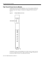
High Speed Frame Service Module
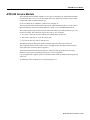
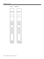
ATM UNI Service Module
4-2
4-6
4-7
4-12
4-13
Circuit Emulation Service Module (4 port)
4-16
Circuit Emulation Service Module (8 port) 4-18
T1/E1 Structured Data Transfer 4-19
T1/E1 Unstructured Data Transfer 4-19
CESM 8-Port LED Indicators 4-21
x Cisco MGX 8220 Reference, Release 4.1
3-10
3-7
AUSM-8T1/E1
4-21
Frame Relay Access Service Module 4-25
STUN Connections 4-25
BSTUN Connections 4-26
FRAS Connections 4-27
Frame Relay to ATM Conversion 4-30
User Interface 4-30
Service Module Back Cards 4-31
T1/T3 Backcards 4-31
X.21 Backcards 4-31
HSSI Backcards 4-31
Redundancy Backcards 4-31
Chapter 5
Service Configuration
5-1
Setting up a Frame Relay Connection 5-1
Via StrataView Plus 5-1
Via the Command Line Interface (CLI) 5-2
AUSM Connections 5-6
Via StrataView Plus 5-6
Via the Command Line Interface
CESM Connections
5-7
5-8
FRASM Connections 5-8
Via the Command Line Interface (CLI)
FRAS BNN Connections 5-9
STUN Connections 5-11
BSTUN Connections 5-13
Chapter 6
MGX 8220 in Stand-alone Applications
Using the Command Line Interface
In-band Access 6-2
Out-of-Bound Access 6-2
The LMI Interface
Chapter 7
6-1
6-1
6-2
Configuring the BNM
6-2
Setting Trap Managers
6-3
VPI/VCI Mapping
VC Connections
VP Connections
5-8
6-3
6-3
6-3
Provisioning FRSM Channels
6-4
Provisioning AUSM Channels
6-5
Installation and Start-up
7-1
Safety Recommendations 7-1
Maintaining Safety with Electricity
Grounding 7-2
7-2
Table of Contents xi
Site Preparation 7-3
Rack and Space 7-3
Power 7-3
Cooling 7-4
Unpacking 7-4
Unpacking Each Container
Parts Checklist 7-5
7-4
Rack Mounting the MGX 8220 Units 7-5
Horizontal Positioning 7-5
Vertical Positioning 7-6
Rack Mounting the Modules 7-9
Rack Mounting the Plenum or Spacer 7-11
Mounting the Electrostatic Wrist Strap 7-11
Collocating Cisco Units in the Same Rack 7-12
Connecting Power for DC Systems 7-14
DC Power to the Shelf 7-14
DC Power to the Fan Cooling Assembly
Connecting Power for AC Systems
AC Input Power 7-18
Available Power 7-18
Monitoring Power Supply Status
Rear Panel Connectors 7-18
7-15
7-18
7-18
Cable Management 7-22
Plenum Chamber Kit 7-22
Main Cooling and Booster Cooling Kit
7-23
Cable Routing 7-25
Power Cable Routing 7-25
Routing Data Cables 7-26
Readying the Cards 7-27
Removing and Installing the Front Cards
Removing and Installing the Back Cards
Making the BNM Trunk Connection
7-28
Making the Service Interface Connections
Alarm Output Connection
7-27
7-28
7-30
7-31
Making External Clock Connections
7-31
Attaching a Control Console 7-31
Dumb Terminal onto the Maintenance Port
Workstation onto the Control Port 7-31
Initial Start-up of the MGX 8220 Shelf
Initial Configuration 7-32
Chapter 8
Repair and Replacement
8-1
Preventive Maintenance
8-1
xii Cisco MGX 8220 Reference, Release 4.1
7-31
7-31
Troubleshooting the MGX 8220 Shelf 8-1
General Troubleshooting Procedures 8-2
Replacing Parts 8-2
Replacing a Front Card 8-3
Replacing a Line Module 8-3
Replacing a DC Power Entry Module 8-4
Replacing the Cooling, Booster, Plenum, and AC Power Assemblies
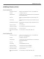
Appendix A
Cabling Summary
Introduction
8-4
A-1
A-1
T3 Trunk Cabling A-1
IMATM T1/E1 Connectors
A-2
Frame Relay Cabling A-2
T1 Cabling A-2
E1 Cabling A-3
X.21 Port Connectors A-5
HSSI Port Connectors A-6
Cabling for RJ-48 Connectors on T1 and E1 Ports
DC Power Cabling
A-7
AC Power Cabling
A-7
A-6
Control and Clock Cabling A-8
Maintenance and Control Ports A-8
Modem Cable A-9
External Clock Input Cabling A-9
External Alarm Cabling
A-10
Standard MGX 8220 Cables
Redundancy “Y” Cable
Appendix B
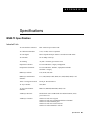
Specifications
A-11
A-12
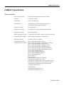
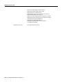
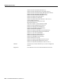
B-1
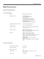
BNM-T3 Specification B-1
Intershelf Link B-1
Card General B-2
BNM-E3 Specification B-3
Intershelf Link B-3
Card General B-4
BNM-155 Specifications B-5
Intershelf Link Specifications
ASC Specification
B-5
B-7
SRM-T1/E1 Specification
B-7
FRSM-4T1 Specification B-9
Service Interface B-9
System Interface B-11
Virtual Circuits B-11
Table of Contents xiii
Card General
B-13
FRSM-4E1 Specification B-13
Service Interface B-13
System Interface B-15
Virtual Circuits B-15
FRSM-8T1 Specification B-17
Service Interface B-17
System Interface B-19
Virtual Circuits B-19
Card General B-21
FRSM-8E1 Specification B-21
Service Interface B-21
System Interface B-23
Virtual Circuits B-23
AUSM Specification (4 Port) B-25
Service Interface (T1) B-25
Service Interface (E1) B-25
ATM Interface B-26
Virtual Circuits B-26
Card General B-27
CESM-4T1/E1 Specification B-28
Service Interface (T1/E1) B-28
Virtual Circuits B-28
IMATM Specification B-29
Physical Interface (T3.T1) RJ48-T3T1-LM
Physical Layer Interface T1 B-30
Physical Layer Interface E1 B-30
Physical Layer Interface T3 B-31
Physical Layer Interface E3 B-31
AIM Groups and Links B-32
Card General B-32
xiv Cisco MGX 8220 Reference, Release 4.1
B-29
L I S T
Figure 1-1
MGX 8220 Shelf
Figure 1-2
MGX 8220/BPX Switch Relationship
Figure 1-3
Remote MGX 8220 Configuration
Figure 2-1
MGX 8220 Shelf Configuration
Figure 2-2
MGX 8220 Shelf Top Level Block Diagram
Figure 2-3
Front View of the MGX 8220 Shelf with Cards Installed
Figure 2-4
Rear View of the MGX 8220 Shelf
Figure 2-5
MGX 8220 Power Entry Module
Figure 2-6
AC Power Assembly (front without grill)
Figure 2-7
AC Power Assembly (rear)
Figure 2-8
DC Power System
2-9
Figure 2-9
Cooling Assembly
2-10
Figure 2-10
MGX 8220 Cabinet
Figure 2-11
ASC Cards
Figure 2-12
Ethernet Extender
Figure 2-13
BNM-T3/E3 Cards
Figure 2-14
MGX 8220 ATM Trunk Cell Format
Figure 2-15
CC, FFCI, EFCI, Supv, PTI, and CLP Fields
Figure 2-16
BNM-155 Cards
Figure 2-17
SRM- T1E1 Card
2-24
Figure 2-18
SRM- 3T3 Cards
2-26
OF
FIGURES
1-1
1-3
1-3
2-2
2-4
2-6
2-6
2-7
2-8
2-8
2-12
2-13
2-14
2-16
2-18
2-18
2-20
Figure 3-1
Maintenance Port Access
Figure 3-2
Control Port Access
Figure 3-3
Control Port Access Via a Terminal Server
Figure 3-4
LAN Port Access to the MGX 8220 Shelf
Figure 3-6
MIB Tree Structure
Figure 3-7
Services Tree
Figure 4-1
IMATM-T3-T1 and IMATM-E3-E1 Front Cards and RJ48-T3T1/E3E1 Back Card
Figure 4-2
IMATM Application
Figure 4-3
IMATM Used with Remote MGX 8220
Figure 4-4
Example FRSM Front Cards
Figure 4-5
BPX 8620 Network with Networking Interworking Connections
Figure 4-6
BPX Network with Service Interworking Connections
Figure 4-7
Example FRSM-HS1 Front Card
3-2
3-3
3-4
3-4
3-11
3-13
4-2
4-3
4-4
4-5
4-6
4-8
4-12
List of Figures xv
Figure 4-8
AUSM Cards
Figure 4-9
CESM Card
4-14
4-17
Figure 4-10
8 Port CESM Cards
Figure 4-11
AUSM-8T1/E1 Front Card
Figure 4-15
Example FRASM Front Cards
Figure 4-16
T1/E1 Backcards
Figure 4-17
T1/E1 Redundancy Back Cards
4-20
4-24
4-29
4-32
4-33
Figure 5-2
Frame Relay Connection through an MGX 8220/BPX Network
Figure 5-3
ATM -ATM Connection Screen
Figure 6-1
MGX 8220 Stand-alone Configuration
Figure 7-1
Mounting Rail Positions
Figure 7-4
Using Angle Bracket to Secure Module to Rack
Figure 7-5
Keyhole Style Bracket
Figure 7-6
Electrostatic Wrist Strap Kit
Figure 7-7
Installed Wrist Strap Kit
Figure 7-8
Multi-system Racks
Figure 7-9
48VDC Male Power Receptacle Viewed facing the Rear of the Shelf
5-3
5-6
6-1
7-5
7-9
7-11
7-12
7-12
7-13
Figure 7-10
PEM Cable Clamp
Figure 7-13
AC Power Assembly Block Diagram
Figure 7-14
AC Cabling for One and Two Shelf Racks
Figure 7-17
Installation of the Cable Management Kit on the Cooling Module
Figure 7-18
Routing Power Cables at the Shelf
Figure 7-19
Routing Power Cables at the Cooling Assembly
Figure 7-20
Routing Data Cables at the Cooling Assembly
Figure 7-21
Front Card Insertion/Extractor Lever
Figure 7-22
Connecting BNM-T3 or BMN-E3 Cables
Figure 7-23
Cabling for Redundant BNM Cards
7-14
7-15
Figure A-1
IMATM T1/E1 Pigtail Cables
Figure A-2
RJ-48 Connectors
Figure A-3
DC Power Connections
Figure A-4
Null Modem Cable
A-7
xvi Cisco MGX 8220 Reference, Release 4.1
A-9
A-7
A-2
7-19
7-20
7-25
7-27
7-30
7-29
7-26
7-26
7-24
LIST
Table 2-1
ASC LED Indicators
Table 2-2
BNM LED Indicators
Table 2-3
BNM-155 LED Indicators
Table 2-4
SRM-T1E1 LED Indicators
Table 3-1
UI Function/Access Path/Protocol Combinations
Table 3-2
Format of Statistics Collection File
Table 4-1
IMATM LED Indicators
Table 4-2
AUSM LED Indicators
Table 4-3
CESM LED 4-Port Indicators
4-18
Table 4-4
CESM 8-Port LED Indicators
4-21
Table 4-5
AUSM-8T1/E1 LED Indicators
Table 5-1
Addcon Parameters
Table 6-1
VPID Ranges
Table 7-1
Plenum Chamber Kit Bill of Material
Table 7-2
Cooling and Booster Kit Bill of Materials
Table A-1
Trunk Cables
Table A-2
T3 Connector Pin Assignments
Table A-3
T1 Trunk/Circuit Line Cabling Specification
Table A-4
T1 Connector Pin Assignments
Table A-5
E1 Trunk/Circuit Line Cabling Specification
A-3
Table A-6
E1 Connector Pin Assignments (unbalanced)
A-3
Table A-7
E1 Trunk/Circuit Line Cabling Specification
A-4
Table A-8
E1 Connector Pin Assignments
Table A-9
Pinouts for X.21 DB-15 Connectors
O F
TABLES
2-15
2-19
2-22
2-25
3-2
3-16
4-4
4-15
4-23
5-5
6-4
7-22
7-23
A-1
A-1
A-2
A-3
A-4
A-5
Table A-10
Pinouts for SCSI-II Connector
Table A-11
DC Power Wiring
A-7
Table A-12
AC Power Cables
A-8
Table A-13
Maintenance and Control Port Cabling
Table A-14
Maintenance and Control Port Pin Assignments
A-8
Table A-15
External Clock Cabling—T3E3-D or SMF-155
A-9
Table A-16
T1 Connector Pin Assignments for EXT. TMG.
A-10
Table A-17
E1 Clock Cabling—T3E3-B
Table A-18
E1 Connector Pin Assignments for EXT.TMG (unbalanced)
Table A-19
External Alarm Cabling
A-6
A-8
A-10
A-10
A-10
List of Tables xvii
Table A-20
Network Alarm Pin Assignments
Table A-21
Standard Cables Available from Cisco
Table A-22
Redundancy Y-Cables
xviii Cisco MGX 8220 Reference, Release 4.1
A-12
A-11
A-11
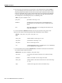
About This Manual
Welcome to the reference manual for the Cisco MGX™ 8220 edge concentrator Release 4.1.
This section discusses:
•
•
•
•
•
Objectives
Audience
Cisco WAN Switching Product Name Change
Related Documentation
Conventions
Cisco documentation and additional literature are available in a CD-ROM package, which ships with
your product. The Documentation CD-ROM, a member of the Cisco Connection Family, is updated
monthly. Therefore, it might be more current than printed documentation. To order additional copies
of the Documentation CD-ROM, contact your local sales representative or call customer service.
The CD-ROM package is available as a single package or as an annual subscription. You can also
access Cisco documentation on the World Wide Web at http://www.cisco.com,
http://www-china.cisco.com, or http://www-europe.cisco.com.
If you are reading Cisco product documentation on the World Wide Web, you can submit comments
electronically. Click Feedback in the toolbar, select Documentation, and click Enter the feedback
form. After you complete the form, click Submit to send it to Cisco. We appreciate your comments.
Objectives
This publication will describe the features, functions, construction and operation of the Cisco
MGX™ 8220 edge concentrator Release 4.1. Details of the MGX 8220 Command Line Interface
and the formats of all the commands are now in a separate MGX 8220 Command Supplement.
Audience
This publication is designed for the person installing the MGX 8220 shelf, who should be familiar
with electronic circuitry and wiring practices and have experience as an electronic or
electromechanical technician. It is also intended for the network administrator who will configure
the MGX 8220 shelf. The installers and network administrators should also be familiar with Cisco
switches, Frame Relay connections, and Cisco wide area networks. During the initial installation of
an MGX 8220 shelf, it is also helpful to have a system administrator on-hand who is familiar with
your network and UNIX servers.
About This Manual xix
Cisco WAN Switching Product Name Change
Cisco WAN Switching Product Name Change
The Cisco WAN Switching products have new names. The BPX switch is now called the Cisco
BPX® 8620 wide-area switch. The AXIS shelf is now called the Cisco MGX™ 8220 edge
concentrator. Any switch in the IGX switch family (IGX 8, IGX 16 and IGX 32 wide-area switches)
is now called the Cisco IGX™ 8400 series-wide area switch. The IGX 8 switch is now called the
Cisco IGX™ 8410 wide-area switch. The IGX 16 switch is now called the Cisco IGX™ 8420
wide-area switch, and the IGX 32 switch is now called the Cisco IGX™ 8430 wide-area switch.
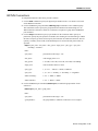
Organization
This manual describes the features, functions, construction and operation of the MGX 8220 shelf
Release 4.1 in the following chapters.
Chapter 1
Introducing the MGX 8220 Shelf
Describes the features and functions of Release 4.1 of the MGX 8220 shelf.
Chapter 2
Common Equipment Description
Provides a detailed description of the MGX 8220 shelf, the core cards, slot
allocation, power modules and fan assemblies.
Chapter 3
Managing the MGX 8220 Shelf
Describes the various facilities provided in MGX 8220 shelf for managing the
shelf.
Chapter 4
MGX 8220 Service Modules
Provides a detailed description of the MGX 8220 service modules that are available
in Release 4.1.
Chapter 5
Service Configuration
Covers the configuration of a service module connection.
Chapter 6
MGX 8220 in Stand-alone Applications
Describes how to use the MGX 8220 shelf as a stand-alone processor.
Chapter 7
Installation and Start-up
Covers site preparation, mechanical installation, installing and readying cards,
making T3, E3, T1, E1 and power connections and initial start-up of the shelf.
Chapter 8
Repair and Replacement
Describes maintenance and troubleshooting procedures and covers the replacement
of cards, power modules and fan assembly.
Appendix A
Cabling Summary
Provides information details on T1, E1, T3, and E3 and control terminal cabling.
Appendix B
Specifications
Provides information about the MGX 8220 system specification.
xx Cisco MGX 8220 Reference, Release 4.1
Related Documentation
Related Documentation
The following Cisco publications contain additional information related to the operation of the Cisco
WAN switching network:
•
Cisco StrataView Plus Operations Guide providing procedures for using the StrataView Plus
network management system.
•
Release 9.1 of the Cisco WAN Switching documentation set including:
— Cisco BPX 8620 BPX Service Node Extended Services Processor Installation and Operation
providing a general description and installation instructions for the Cisco BPX 8620.
— Cisco IPX Reference providing a general description and technical details of the Cisco
IPX narrowband node.
— Cisco IGX 8400 Series Reference providing a general description and technical details of the
multi-band Cisco IGX 8400 series.
— Cisco MGX 8220 Reference providing a general description and technical details of the
MGX 8220 node.
— Cisco WAN Switching Command Reference providing detailed information on the command
line interfaces used in operating a Cisco WAN switching network.
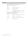
Conventions
This publication uses the following conventions to convey instructions and information.
Command descriptions use these conventions:
•
•
•
•
Commands and keywords are in boldface.
Arguments for which you supply values are in italics.
Elements in square brackets ([ ]) are optional.
Alternative but required keywords are grouped in braces ({ }) and are separated by
vertical bars ( | ).
Examples use these conventions:
•
•
•
•
Terminal sessions and information the system displays are in screen font.
Information you enter is in boldface
screen
font.
Nonprinting characters, such as passwords, are in angle brackets (< >).
Default responses to system prompts are in square brackets ([ ]).
Note Means reader take note. Notes contain helpful suggestions or references to materials not
contained in this manual.
Caution Means reader be careful. In this situation, you might do something that could result in equipment
damage or loss of data.
Warning This warning symbol means danger. You are in a situation that could cause bodily injury. Before
you work on any equipment, you must be aware of the hazards involved with electrical circuitry and familiar
with standard practices for preventing accidents. (To see translated versions of this warning, refer to the
Regulatory Compliance and Safety Information document that accompanied your product.)
About This Manual xxi
Conventions
xxii Cisco MGX 8220 Reference, Release 4.1
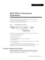
CHAPTER
1
Introducing the MGX 8220 Shelf
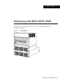
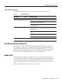
This chapter describes the features and functions of Release 4.1 of the Cisco MGX 8220 edge
concentrator. (See Figure 1-1.)
Figure 1-1
MGX 8220 Shelf
Introducing the MGX 8220 Shelf 1-1
MGX 8220 System Overview
MGX 8220 System Overview
MGX 8220 shelf is designed on the philosophy that large scale deployment of narrowband and
medium-band services is best handled using an ATM infrastructure. In fact, support of these services
can, by themselves, cost justify an ATM infrastructure. The same infrastructure can then be used to
provide broadband services to customers when and where they are needed.
The MGX 8220 shelf is an adjunct shelf to the BPX switch. Architecturally it provides:
•
A means for flexibly providing many narrowband and/or medium-band ATM and non-ATM
service interfaces without consuming BPX switch slots.
•
Conversion of non-ATM traffic streams to and from ATM traffic streams using Adaptation Layer
standards.
•
A means for concentrating the traffic from the narrowband and/or medium-band interfaces onto
the broadband ATM ports of the BPX switch.
The MGX 8220 shelf can also be used as a stand-alone unit in which it can communicate with third
party devices over ATM UNI and NNI links provided there is inter-operability between the third
party devices and the MGX 8220 ATM port.
Service Interfaces
The MGX 8220 shelf is a flexible standards-based service access platform. The MGX 8220 shelf can
support a wide range of services over narrowband and mid-band user interfaces, mapping all the
service traffic to and from ATM, based upon standardized interworking methods. The aggregated
traffic is sent/received over an ATM interface to an ATM switch (BPX switch), using up only a single
port on the ATM switch.
The MGX 8220 shelf supports up to 80 channelized or non-channelized T1 and E1 interfaces on a
single shelf providing support for Frame Relay UNI and NNI; ATM UNI, NNI, and FUNI; Frame
Relay to ATM network interworking; Frame Relay to ATM service interworking, circuit emulation
services, and Frame Relay Access services for supporting IBM SNA networks. Using the Service
Resource Module (SRM), multiple T1 interfaces can be supported on physical T3 lines.
The MGX 8220 shelf also supports the use of Inverse Multiplexing for ATM (IMA) to provide ATM
trunking below T3/E3.
The system’s modular, software-based architecture enables it to support these and other additional
user services in the future, through downloadable software upgrades or new hardware modules.
Standards-Based Conversion to ATM
All user information received by the MGX 8220 shelf interfaces is converted into 53-byte ATM cells,
using standard ATM Adaptation Layers (AALs) for transport over the ATM backbone network. Cell
segmentation and reassembly (SAR) and other adaptation functions are distributed to each interface
module to eliminate system bottlenecks.
•
•
For Circuit Emulation Services AAL1 is used.
•
For Frame Relay to ATM service interworking, both transparent and translation modes are
supported to map FR to native ATM AAL5.
•
For Frame Forwarding AAL5 is used.
For Frame Relay (FR to ATM network interworking) AAL5 and FR-SSCS (Frame Relay Service
Specific Convergence Sublayer) are used.
1-2 Cisco MGX 8220 Reference, Release 4.1
MGX 8220 System Overview
Aggregation of Traffic into ATM Networks
Each MGX 8220 shelf connects to the BPX switch across:
•
A T3 or E3 ATM to a BNI or T3/E3 BXM module on the BPX switch
or
•
A SMF SONET ATM link to a BXM-155-8 port or BXM-155-4 port on the BPX switch
Thus, the MGX 8220 shelf supports aggregation of traffic up to 80 T1 or E1 access ports or up to
1240 64-Kbps subscribers, onto a single T3, E3, or OC-3c trunk, using only a single port on the
BPX switch.
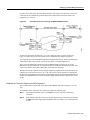
The MGX 8220 shelf should normally be collocated with the BPX switch. Figure 1-2 shows how the
MGX 8220 shelf usage is envisioned in Release 4.1.
Figure 1-2
MGX 8220/BPX Switch Relationship
For remote locations with limited bandwidth needs, the MGX 8220 shelf can be remotely located
from the BPX switch using IMA trunk machines as shown in Figure 1-3.
Figure 1-3
Remote MGX 8220 Configuration
The following subsections provide an overview of the MGX 8220 shelf, the Release 4.1 cards, and
management capabilities. In-depth details are provided in subsequent chapters.
MGX 8220 Shelf
Physically, the MGX 8220 shelf consists of cards in a 19 inch rack mountable shelf.
The shelf can be powered either from a -48V DC source or from a 220-240V AC source. The DC
version includes DC power entry modules that can be mounted in the shelf. The AC version requires
an external rack mounted, AC Power Module. Both versions require a rack mounted cooling
assembly. Multiple MGX 8220 shelves can be mounted in the same rack sharing power and cooling
assemblies.
The MGX 8220 shelf contains 16 slots where each slot can accommodate a front card and a back
card. The front row is used for function modules, cards that perform more complex functions within
the unit (for example, frame relay to ATM conversion). The back row is used for line modules, cards
that provide interfaces to one or more transmission lines connected to the MGX 8220 shelf
(for example, the trunk line to the BPX switch or an RS-232 line to a control terminal).
Introducing the MGX 8220 Shelf 1-3
MGX 8220 System Overview
MGX 8220 Cards
Unless a service module uses the SRM 3T3 distribution bus, MGX 8220 cards are installed as a pair
consisting of a front card (function module) and a matching back card (line module) in the same slot,
except for the SRM-T1E1 card which only has a front card. Communication between slots is
achieved through buses in the shelf backplane.
Release 4.1 consists of the following module pairs:
•
MGX 8220 Shelf Controller(ASC)
This is a pair of cards providing overall control of the shelf and providing line interfaces to
maintenance and control ports which are used for user configuration and management of the
shelf.
•
Broadband Network Module (BNM-T3)
This is a pair of cards which together provide a UNI/NNI interface to the attached BPX switch
over a T3 ATM interface.
•
Broadband Network Module (BNM-E3)
This is a pair of cards which together provide a UNI/NNI interface to the attached BPX switch
over a E3 ATM interface.
•
Broadband Network Module (BNM-155)
This is a pair of cards which together provide the interface to the attached BPX switch over a
SONET ATM interface.
•
Frame Service Module for T1 (FRSM-4T1)
This card provides interfaces for up to four T1 lines, each of which can support one 56 kbps or
one Nx64 kbps FR-UNI, FR-NNI port, ATM-FUNI, or a Frame Forwarding port.
•
Frame Service Module for T1 (FRSM-8T1)
This card provides interfaces for up to eight T1 lines, each of which can support one 56 kbps or
one Nx64 kbps FR-UNI, FR-NNI port, ATM-FUNI, or a Frame Forwarding port.
•
Frame Service Module for T1 channelized (FRSM-4T1-C)
This card provides interfaces for up to four T1 lines, each of which can support multiple (up to
24) 56 kbps or Nx64 kbps FR-UNI, FR-NNI, ATM-FUNI, or a Frame Forwarding port.
•
Frame Service Module for T1 channelized (FRSM-8T1-C)
This card provides interfaces for up to eight T1 lines, each of which can support multiple (up to
24) 56 kbps or Nx64 kbps FR-UNI, FR-NNI, ATM-FUNI, or Frame Forwarding port.
•
Frame Service Module for E1 (FRSM-4E1)
This card provides interfaces for up to four E1 lines, each of which can support one 56 kbps or
one Nx64 kbps FR-UNI, FR-NNI, ATM-FUNI, or Frame Forwarding port.
•
Frame Service Module for E1 (FRSM-8E1)
This card provides interfaces for up to eight E1 lines, each of which can support one 56 kbps or
one Nx64 kbps FR-UNI, FR-NNI, ATM-FUNI, or Frame Forwarding port.
•
Frame Service Module for E1, channelized (FRSM-4E1-C)
This card provides interfaces for up to four E1 channelized frame relay lines, each of which can
support multiple (up to 31) 56 kbps or Nx64 kbps FR-UNI, FR-NNI, ATM-FUNI, or Frame
Forwarding port.
•
Frame Service Module for E1, channelized (FRSM-8E1-C)
This card provides interfaces for up to eight E1 channelized frame relay lines, each of which can
support multiple (up to 31) 56 kbps or Nx64 kbps FR-UNI, FR-NNI, ATM-FUNI, or Frame
Forwarding port.
1-4 Cisco MGX 8220 Reference, Release 4.1
MGX 8220 System Overview
•
ATM UNI Service Module for T1 (AUSM-4T1)
This card provides interfaces for up to four T1 lines, each of which can support one T1 ATM UNI
or ATM NNI.
•
ATM UNI Service Module for E1 (AUSM-4E1)
This card provides interfaces for up to four E1 lines, each of which can support one E1 ATM UNI
or ATM NNI.
•
ATM UNI Service Module for T1 (AUSM-8T1)
This card provides interfaces for up to eight T1 lines, each of which can support one T1 ATM
UNI or ATM NNI plus additional support for IMA.
•
ATM UNI Service Module for E1 (AUSM-8E1)
This card provides interfaces for up to eight E1 lines, each of which can support one E1 ATM
UNI or ATM NNI plus additional support for IMA.
•
Circuit Emulation Service Module for T1 (CESM-4T1)
This card provides interfaces for up to four T1 lines, each of which is a 1.544 Mbps unstructured
synchronous data stream.
•
Circuit Emulation Service Module for E1 (CESM-4E1)
This card provides interfaces for up to four E1 lines, each of which is a 2.048 Mbps unstructured
synchronous data stream.
•
Circuit Emulation Service Module for T1 (CESM-8T1)
This card provides interfaces for up to eight T1 lines, each of which is a 1.544 Mbps structured
or unstructured synchronous data stream.
•
Circuit Emulation Service Module for E1 (CESM-8E1)
This card provides interfaces for up to eight E1 lines, each of which is a 2.048 Mbps structured
or unstructured synchronous data stream.
•
Inverse Multiplexing for ATM Trunk Module—T3 to T1 (IMATM-8T1)
This card acts as an extension of the BPX BNI card and permits the BPX ATM trunk to be used
over multiple (up to 8) T1 lines instead of a single T3 line.
•
Inverse Multiplexing for ATM Trunk Module—E3 to E1 (IMATM-8E1)
This card acts as an extension of the BPX BNI card and permits the BPX ATM trunk to be used
over multiple (up to 8) E1 lines instead of a single E3 line.
•
Frame Relay Access Service Module (FRASM-8T1)
This card provides interfaces for up to eight T1 lines for the support of IBM SNA networks. Both
binary synchronous (BSC) and synchronous data link control (SDLC) protocols are supported.
•
Service Resource Module (SRM-T1E1)
This card provides loopback and bit error rate testing (BERT) functions and 1:N redundancy for
the service modules.
•
Service Resource Module (SRM-3T3)
This card provides loopback and bit error rate testing (BERT) functions and 1:N redundancy for
the service modules. Three T3 service lines are also provided to carry multiple T1 service lines
which are then mapped to T1 based service module slots and ports in the MGX 8220 shelf.
The ASC and the BNM modules must always be present in an MGX 8220 shelf and are referred to
as the core modules. The MGX 8220 shelf supports redundant core modules where one ASC/BNM
set is an active set and a second ASC/BNM is a standby set. In the event of a malfunction, the standby
set automatically takes over as the active set. The SRM is optional. If present, it is part of the core
card set, with switchover to the standby upon a malfunction of the active BNM or ASC.
Introducing the MGX 8220 Shelf 1-5
New in Release 4.1
MGX 8220 Management
The functions and operation of the MGX 8220 shelf are achieved through downloaded firmware. The
firmware controls the overall operation of the shelf and responds to configuration and other The
MGX 8220 shelf has a command repertoire of over 60 user commands which are used to configure
and display the various operational parameters of the shelf.
The current status and configuration parameters of the MGX 8220 modules are maintained in a
Management Information Base (MIB) which is updated by the firmware as changes in status and
configuration occur. The MIB can be interrogated using SNMP commands.
Most of the functions of the MGX 8220 shelf Release 4.1 can be effected through the graphical user
interface provided in StrataView Plus Release 9.1.
The ASC module includes three ports for user input of management commands. A further means of
management access is provided in-band over the ATM trunk.
The maintenance port is a simple RS-232 port for direct connection to an alpha-numeric terminal
into which the user can type commands through a Command Line Interface (CLI).
The control port (SLIP protocol only), the LAN (Ethernet) port and the in-band ATM connection all
support the CLI (via Telnet), TFTP and SNMP protocols for communicating with the MGX 8220
shelf.
New in Release 4.1
This section provides a very brief description of the new MGX 8220 shelf features that have been
added since Release 4.0:
•
New circuit emulation service modules (CESM) are available which supports eight T1 circuits,
or eight E1 circuits. These are in addition to the four T1/E1 cards provided in earlier releases.
•
A new Frame Relay Access Service Module (FRASM) is available for the support of IBM SNA
networks over T1 lines.
•
The use of the MGX 8220 in stand-alone (non-BPX 8620 networks) applications.
1-6 Cisco MGX 8220 Reference, Release 4.1
CHAPTER
2
Common Equipment Description
This chapter provides a description of the common equipment hardware modules that make up the
MGX 8220 shelf Release 4.1. The optional service modules are described in Chapter 4, “MGX 8220
Service Modules”.
Common equipment of the MGX 8220 shelf consists of the following modules:
•
MGX 8220 hardware shelf, which includes:
— card cage
— backplane
— power entry module housing
•
Core cards installed in the shelf, which include:
— MGX 8220 Shelf Controller (ASC)
— Broadband Network Module (BNM)
— Service Resource Module (SRM) (optional)
•
•
•
•
•
Main cooling assembly
Cooling booster assembly (for certain multi-shelf configurations only)
Power entry module (for DC powered systems only)
AC power assembly (for AC powered systems only)
Optional cabinet
System Overview
The MGX 8220 shelf is a 19 inch rack mountable shelf which provides 16 slots for holding the
modules (card sets) that provide the MGX 8220 functionality. Each slot is designed to house two
cards, a front card and a back card. Cards are installed in a slot as a two card set referred to as a
module. A backplane runs across all 16 slots which provides signal connections between front and
back cards and between slots. The backplane also provides power distribution to all slots from dual
(redundant) power entry modules installed in the bottom of the shelf.
All external line connections (for example, Frame Relay lines, the ATM trunk line and control
console RS-232 lines) are made on the back cards at the rear of the shelf.
A cooling assembly containing the MGX 8220 cooling fans consists of a rack mounted fan unit
below the main MGX 8220 shelf and either a plenum or spacer unit which is mounted above the
shelves. The cooling assembly is capable of cooling up to two MGX 8220 shelves in the same rack.
Common Equipment Description 2-1
System Overview
In racks that contain more than two shelves, a booster cooling unit is used to provide additional
cooling. The cooling assembly is powered from the main MGX 8220 shelf. An external view of a
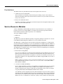
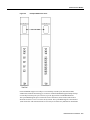
single MGX 8220 shelf configuration is shown in Figure 2-1. The arrangement of assemblies in a
rack including cases for multiple MGX 8220 shelves is provided in chapter 7, “Installation and
Start-up”.
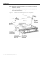
Figure 2-1
MGX 8220 Shelf Configuration
An MGX 8220 shelf consists of various kinds of modules. Each module consists of a larger front
card function module which provides the functionality of the module and a smaller back card which
provides the connectors and interfaces for the external lines that the module supports.
The MGX 8220 Shelf Controller (ASC) is the module that provides the overall control of the shelf.
Each MGX 8220 shelf must have at least one ASC and may be configured with a second (redundant)
ASC.
The ASC back card also provides the RS-232 ports and Ethernet port for attaching a control terminal
or workstation.
The Broadband Network Module (BNM) provides the interface to the BPX network over either a
T3 or E3 line using the ATM STI, UNI, or NNI protocol and the BPX BNI or BXM cards, or a
SONET OC-3 or STS-3c line using ATM UNI/B-ICI protocol. Each MGX 8220 shelf must have at
least one BNM and may be configured with an identical second (redundant) BNM. The BNM also
provides:
•
•
•
an external alarm interface
a fan monitor interface
a port for accepting an external T1 or E1 clock source
2-2 Cisco MGX 8220 Reference, Release 4.1
System Overview
The Service Resource Module (SRM) communicates with all service modules over a Bit Error Rate
Test (BERT) bus and provides the capability for testing T1 and E1 and subrate service module lines.
The SRM can issue various loopup and loopdown commands towards the CPE and generate test bit
patterns for any user specified Nx64 kbps port. The SRM can also provide 1:N redundancy for
FRSM, AUSM, and CESM cards. The SRM is an optional card.
Note The ASC and the BNM together are referred to as the core modules and at least one set must
be installed in the shelf. If redundancy is required, BOTH the ASC and the BNM must be configured
with redundant cards. If configured, the SRM is also part of the core modules. Failure of an ASC or
BNM will cause switchover to the redundant ASC, BNM and SRM cards. Failure of the active SRM
card will only cause switchover if the SRM is included in the redundant set as well.
The Service Modules provide the customer interfaces. Up to ten service modules may be configured
in a shelf. Service modules may be intermixed in the same shelf.
The overall operation of the shelf is to:
•
Accept customer traffic received over the service interface lines, adapt them to ATM, and
multiplex them onto the BNM trunk for transmission to the BPX network.
•
Accept ATM cells received over the BNM trunk, map them into the specified service protocols,
and transmit them over the appropriate service interface.
The Inverse Multiplexing for ATM Trunk Module (IMATM) is housed in the MGX 8220 shelf in a
service module slot. It is an extension to the BPX 8620 BNI card that supports BPX 8620 ATM
trunks over multiple (up to 8) T1 and E1 lines instead of single T3 or E3 line. The IMATM does not
use the MGX 8220 cell bus as other service modules do, but provides its own trunk to the BPX 8620.
In performing these functions the MGX 8220 shelf collects a wide variety of statistics about frames
and cells, error conditions, congestion, and so on.
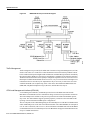
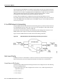
A simplified block diagram of the MGX 8220 hardware is shown in Figure 2-2. As shown by the
dashed lines, the ASC, SRM, and cell bus are all 1 for 1 redundant. This means that one ASC, BNM,
SRM slot set is attached to one cell bus, and the remaining ASC, BNM and SRM slot set is tied to
the other cell bus.
Common Equipment Description 2-3
System Overview
Figure 2-2
MGX 8220 Shelf Top Level Block Diagram
Traffic Management
Traffic management is provided by the MGX 8220 Connection Congestion Management (ACCM)
feature. This feature is a virtual source/virtual destination rate based closed loop feedback scheme
between nodes based upon ForeSight and the ATM Forum Available Rate specification. Periodically
the round trip delay (RTD) of a cell to the far end and back is calculated for each actual connection.
The RTD is used to determine how frequently ForeSight rate adjustment cells are sent to the far end.
Based upon available bandwidth and current access rate, every few microseconds a ForeSight cell is
transmitted to the far end with any rate adjustments it may be necessary to make better use of the
available bandwidth (rate is adjusted up, down or fast down). The MGX 8220 MIB includes rate
(MIR, PIR, and QIR) and adjustment (Up%, Down%, and Fast-Down%) objects.
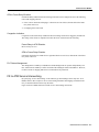
ATM Local Management Interface (ATM LMI)
A Local Management Interface (ATM LMI) operates between the MGX 8220 shelf and the
BPX 8620. The ATM LMI is used to communicate change of status of semi-permanent connections.
The ATM LMI protocol conforms to the protocol specified in ITU-TS Recommendation Q.2931,
Sept. 1994. The ATM LMI also supports optional proprietary extensions to the ATM LMI for the
reporting of node information and BNI queue configurations.
The two end points of the ATM LMI signaling are an ATM LMI process in the BCC in the BPX 8620
and an ATM LMI process in the ASC in the MGX 8220 shelf. The ATM LMI PDUs are transported
over an AAL5 connection (VPI=3/VCI=31) between the BNI on the BPX 8620 side and the BNM
on the MGX 8220 side. The ATM LMI process in the BPX 8620 can support ATM LMI connections
for up to 16 MGX 8220 shelves.
2-4 Cisco MGX 8220 Reference, Release 4.1
MGX 8220 Shelf Hardware
The Cisco ATM LMI extension (which must be specifically enabled) uses a Node Update Status
Message which is sent (BPX 8620 to MGX 8220 shelf or MGX 8220 shelf to BPX 8620) whenever
a change in Node Name, Node IP Address, Major Alarm Status, or Minor Alarm Status occurs. The
message may optionally contain Qbin Status thereby allowing MGX 8220 to configure the BNI port
egress queues.
Auto Card Restore
Auto Card Restore is a feature which allows a service module card to be removed and be hot plug
replaced with another service module card keeping the same configuration. With this feature, the
ASC maintains a copy of the configuration for each active service module.
MGX 8220 Shelf Hardware
The MGX 8220 shelf is a 19 inch rack mountable unit conforming to the EIA RS-310-C standard
and measuring:
•
•
•
8.75 inches (5u) high
17.45 inches wide
21.25 inches deep (without cards) or 23 inches deep with back cards and fan connector.
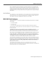
The shelf contains a card cage with 16 slots. The slots are numbered 1 to 16 from the left looking at
the front of the shelf.
A backplane runs across the card cage spanning all 16 slots. The backplane is positioned
approximately 14 inches from the front of the cage allowing a function module card to be inserted
in the slot from the front and a smaller line module card to be inserted in the slot from the rear.
Slots 1 and 2 are reserved for BNM cards (single or a redundant pair) and slots 3 and 4 are reserved
for ASC cards (single or a redundant pair). Slots 15 and 16 are reserved for the SRM (single or
redundant pair). Slots 1, 3, and 15 work together as an active or standby set, the same is true for slots
2, 4 and 16. Slots 5 through 14 (10 slots) are available for Service Modules (or IMATMs). For
1:N redundancy of T1/E1 service modules standby cards must use slots 12, 13, and 14.
The shelf may house redundant power entry modules which are small cards installed horizontally in
the bottom rear of the shelf. The MGX 8220 shelf is powered by –48V DC power sources (single or
redundant pair). Each power entry module is equipped with a circuit breaker. The shelf also provides
a power receptacle for a cable to the cooling assembly which is mounted in the rack below the
MGX 8220 shelf (or shelves).
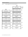
The backplane provides redundant system buses for communication between slots, power
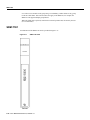
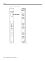
distribution to all slots and communication between front and back cards. Figure 2-3 and Figure 2-4
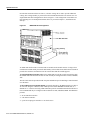
show the front and rear views of the MGX 8220 shelf.
Common Equipment Description 2-5
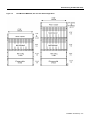
MGX 8220 Shelf Hardware
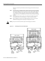
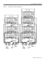
Figure 2-3
Front View of the MGX 8220 Shelf with Cards Installed
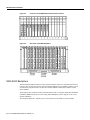
Figure 2-4
Rear View of the MGX 8220 Shelf
MGX 8220 Backplane
The MGX 8220 backplane contains a main system bus and the cell bus for communication between
card slots. The cell bus consists of two pairs of unidirectional buses (for redundancy) which are used
for transferring cells between the cell bus slave modules (FRSM, AUSM, ASC) and the cell bus
master (BNM).
The backplane also contains a local bus which permits the ASC to configure and monitor the BNM
and SRM, a BERT bus for bit error rate testing, and a Redundancy bus for support of 1:N service
module redundancy.
The backplane distributes –48VDC power to all card slots and all modules are hot insertable.
2-6 Cisco MGX 8220 Reference, Release 4.1
Power Entry Options
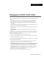
Typical MGX 8220 Hardware Weights
Hardware
Weight (lbs)
MGX 8220 shelf with 16 boards
68
MGX 8220 main cooling unit
20
MGX 8220 booster cooling unit
14
MGX 8220 plenum
8
Average single MGX 8220 board
1.9
Power Entry Options
DC Powered Systems
In DC powered systems MGX 8220 supports one or two power entry modules (PEMs) each of which
can be connected to its own independent 48VDC supply. The power entry modules are installed
horizontally, side by side in the bottom rear of the shelf. (See Figure 2-4.) Each module is powered
from a 48VDC power source via three wires:
•
•
•
positive ground
–48 V DC
safety ground
The 48 VDC cable is connected to the power entry module through a 3- position EURO Block
connector. The two modules provide power supply redundancy. Each power entry module is capable
of supplying enough power for a fully loaded MGX 8220 shelf.
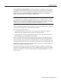
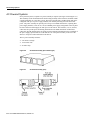
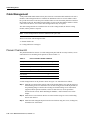
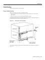
An illustration of a power entry module is shown in Figure 2-5.
Figure 2-5
MGX 8220 Power Entry Module
Each power entry module contains its own circuit breaker which also acts as an ON/OFF switch. The
circuit breaker is closed by pressing in the large black button until it latches in the closed position.
The circuit breaker is opened by pressing the smaller red button. The DC PEM also includes a
bracket which is attached to the PEM to provide cable strain relief. Refer to Chapter 7, “Installation
and Start-up” for details.
Common Equipment Description 2-7
Power Entry Options
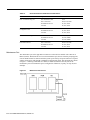
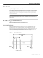
AC Powered Systems
In AC powered systems, a separate AC power assembly is required. (See Figure 2-6 and Figure 2-7.)
This assembly is rack mounted under the shelf cooling assembly in the rack and is available in both
a single and double AC source line version. The power assembly has a modular design and can be
configured with up to six power supply modules, each module providing 875 watts of 48 VDC
power. The power assembly can provide power for up to four MGX 8220 shelves, requiring three
power supply modules, or four for a (1 for N) redundant power supply configuration. The rear panel
has four connectors which supply 48 VDC power to the shelves. The first three (1A, 2A, and 3A)
connectors also provide power monitoring information to the MGX 8220 shelf. Another three
connectors (1B, 2B, and 3B) on the rear panel provide monitoring information for the second half of
the power supply. Special cables are used from the rear of the power assembly to the rear of the
shelves to feed power and monitor data to the shelves.
The AC power assembly measures:
•
•
•
5.25 inches (3u) high
17.45 inches wide
23 inches deep
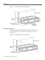
Figure 2-6
AC Power Assembly (front without grill)
Figure 2-7
AC Power Assembly (rear)
2-8 Cisco MGX 8220 Reference, Release 4.1
Cooling Assemblies
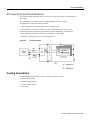
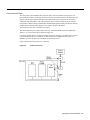
DC Power Drain and Circuit Protection
Each card in an MGX 8220 shelf draws an average of 21 watts with a worst case shelf current of
14.40 amps.
The circuit breaker in the DC Power Entry Module (PEM) is rated at 15.00 amps.
The MGX 8220 circuits are protected as follows:
•
•
The backplane has a 5 amp fast blow fuse for each slot position.
Each board has a 1.5 amp circuit breaker in the -48 VDC line to the DC/DC converter.
Each MGX 8220 board is equipped with a DC/DC converter (Shindengen—HGG05006 or
AT&T—JW030A) which has an automatic current limited to 5 volts output.
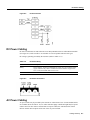
A schematic of the DC power system is shown in Figure 2-8.
Figure 2-8
DC Power System
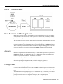
Cooling Assemblies
The MGX 8220 cooling assembly consists of multiple rack-mounted units:
•
•
•
•
main cooling assembly
booster cooling assembly
plenum exhaust chamber
spacer unit
Common Equipment Description 2-9
Cooling Assemblies
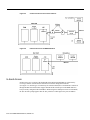
Main Cooling Assembly
The main cooling assembly measures:
•
•
•
5.25 inches (3u) high
17.45 inches wide
22 inches deep
The main cooling assembly is capable of providing cooling for up to two MGX 8220 shelves and is
mounted in the rack below the shelf (or shelves). The cooling assembly consists of fans which draw
air through the front and exhaust air upwards through the shelf. An illustration of the cooling
assembly is shown in Figure 2-9.
Figure 2-9
Cooling Assembly
Booster Cooling Assembly
The booster cooling assembly measures:
•
•
•
3.5 inches (2u) high
17.45 inches wide
22 inches deep
The booster cooling assembly is used in racks with more than two MGX 8220 shelves and is
mounted above the shelves cooled by the main cooling assembly and below the shelves to which the
booster cooling is to be provided. The booster cooling assembly consists of fans which draw air from
the shelves below and exhaust air upwards through the shelf or shelves above. Each booster supports
an additional two MGX 8220 shelves. A system of up to six MGX 8220 shelves can be supported
(using one main cooling unit and two booster cooling units).
Cooling Assembly Power
For both cooling assemblies, power is supplied to the connector at the rear of the cooling assembly
by a cable running from the connector in the middle bottom rear of the MGX 8220 shelf.
The assemblies provide output signals to the shelf. Using these signals, the performance of the
cooling assemblies can be monitored by the BNM cards. The cable delivering DC power to the
cooling assembly from the MGX 8220 shelf also carries these signals to the BNM via the backplane.
The signals are such that the model of cooling assembly can be identified and the speed of each fan
can be monitored (each fan generates a fixed number of square-wave pulses per revolution allowing
the speed of the fan to be determined).
2-10 Cisco MGX 8220 Reference, Release 4.1
Optional Cabinet
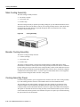
The Plenum Exhaust Chamber
The Plenum chamber measures:
•
•
•
3.5 inches (2u) high
17.45 inches wide
22 inches deep
The exhaust plenum chamber is used in installations where the top of the unit must be enclosed. The
plenum chamber is mounted in the rack immediately above the shelf (shelves). The chamber delivers
air from the shelf below and out to the rear of the rack. The plenum chamber is preferred.
Spacer Unit
The spacer unit measures:
•
•
•
1.75 inches (1 mounting unit) high
17.45 inches wide
22 inches deep
If used, the spacer unit is mounted in the rack immediately above the shelf (shelves).
The plenum chamber and spacer units are alternative methods for exhausting the cooling air from
the rack. Either method can be used but not both. The spacer does not support the attachment of a
cable management kit.
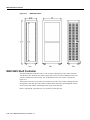
Optional Cabinet
A cabinet is available from Cisco which can be used to install the MGX 8220 shelf, the BPX switch,
ESP, and the IGX 8400 series wide-area switch. Systems preconfigured in a cabinet can be ordered
from Cisco.
The cabinet is essentially a 19 inch rack with panels on all sides (including top and bottom) except
the front. The rear panel is a louvered hinged door. The cabinet is equipped with casters, brakes and
leveling bolts. (See Figure 2-10.) The cabinet also includes earthquake safety holes so the cabinet
can be secured to the floor using studs.
The vertical height of the cabinet (including casters) is 80.31inches providing 71.81 inches (41 rack
mounting units) of vertical rack space.
The cabinet is 23 inches wide and 36 inches deep. Since MGX 8220 modules are typically 22 inches
deep, the cabinet provides approximately 12 inches of space behind the mounted MGX 8220
modules for cables and cable management hardware.
Note Modules are installed in the cabinet in the same manner as installed in a 19 inch rack.
Modules are installed by inserting them into the front of the cabinet and attaching them to the internal
racks. All cables are connected through the rear door.
Common Equipment Description 2-11
MGX 8220 Shelf Controller
Figure 2-10
MGX 8220 Cabinet
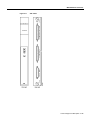
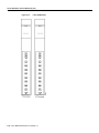
MGX 8220 Shelf Controller
The MGX 8220 Shelf Controller (ASC) is a two-card set consisting of an ASC front card and an
ASC-BC back card. The shelf may contain a single ASC card set or a dual (redundant) card set. The
cards are installed in slots three and/or four. An illustration of the ASC card set is provided in
Figure 2-11.
The function of the ASC is to provide a user interface to provide overall control, configuration, and
management of the shelf. The ASC interfaces with the other cards in the shelf through the cell bus
on the one side and with the user through console ports on the other side.
Refer to Appendix B, “Specifications”, for a summary of cable pin-outs.
2-12 Cisco MGX 8220 Reference, Release 4.1
MGX 8220 Shelf Controller
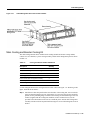
Figure 2-11
ASC Cards
Common Equipment Description 2-13
MGX 8220 Shelf Controller
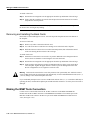
Console Ports
There are three ASC hardware console ports located on the faceplate of the back card.
The maintenance port is an RS-232 port used by a direct connect alpha-numeric terminal for
inputting Command Line Interface (CLI) commands. Y-cables cannot be used on this port. This port
must be used to make initial IP address assignments on the other ports before the other ports can be
used.
The control port and IEEE 802.3 (Ethernet, LAN AUI) ports are used for inputting commands and
file transfers (statistics collection and firmware download). The control port communicates using
SLIP and the Ethernet port communicates using IP. These ports support TFTP, SNMP, and CLI
(through Telnet). The control port may be used with Y-cables for redundancy when a second
ASC card set is present.
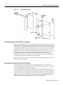
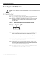
Some Ethernet transceivers with integrated DB-15 connectors cannot be connected directly to the
LAN AUI Ethernet port on the MGX 8220 ASC back card because of interference with the
ASC back card extractor levers. To overcome this problem two Ethernet transceiver extenders (one
each for a primary and secondary ASC card) are provided.
If you encounter difficulty in connecting an Ethernet transceiver, install an extender on each
ASC card as follows:
1 With the retaining clip on the LAN AUI port in the unlocked (up) position, connect the Ethernet
transceiver extender to the LAN AUI port on the ASC back card as shown in Figure 2-12.
2 Push the port retaining clip into the locked (down) position to secure the connection.
3 With the retaining clip on the transceiver extender in the unlocked (up) position, connect the
Ethernet transceiver to the extender as shown in the diagram.
4 Push the extender retaining clip into the locked (down) position to secure the connection.
Figure 2-12
Ethernet Extender
Note Additional access for shelf management is available through in-band communication over the
ATM trunk.
2-14 Cisco MGX 8220 Reference, Release 4.1
Broadband Network Modules
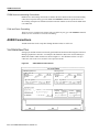
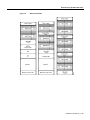
ASC LED Indicators
The ASC LED indicators are located on the faceplate of the front card. (Refer to Table 2-1.)
Table 2-1
ASC LED Indicators
Type of LED
Color
Meaning of LED
ACTIVE (ACT) LED
Green
On indicates the card is active.
STANDBY (STBY) LED
Yellow
Slow blink without Active LED indicates the card is in the boot state.
Fast blink with Active LED indicates the ASC is downloading to
another card or is being downloaded.
Steady yellow indicates the card is in Standby state. The firmware is
executing ADMIN code.
FAIL (FAIL) LED
Red
Steady Red with Active and Standby LEDs off indicates the card is in
the Reset condition, the card has failed, or the card set is not complete
(no line module).
Steady Red with Active LED on indicates the card was active prior to
failing.
Steady Red with Standby LED on indicates the card was standby prior
to failing.
Blinking Red indicates the card is in the power up state.
LAN (LAN) LED
Green
On indicates receive activity through the LAN port. A green flash is
seen for every packet received.
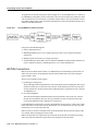
Broadband Network Modules
The BNM card set provides the MGX 8220 trunk interface to a BPX 8620 node. There are two major
types of BNMs, one supports a T3 or E3 trunk and one supports a 155 Mbps SONET SMF trunk.
Each MGX 8220 shelf must be equipped with at least one BNM installed in slots 1 or 2. A second,
redundant, BNM may be installed also in slots 1 or 2. The primary and the redundant BNMs must
be of the same type. Each BNM installed consists of a front and back card set.
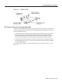
BNM-T3/E3
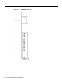
The Broadband Network Module-T3E3 (BNM-T3E3) is a two-card set consisting of a BNM-T3 or
E3 front card and a T3E3-D-BC or T3E3-B-BC back card. Either back card can be used with either
front card except that the BNC clock connector only works for E1 clock sources. The shelf may
contain a single BNM card set or a dual (redundant) card set. The cards are installed in slot 1 and/or
slot 2.
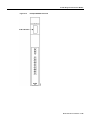
An illustration of the BNM-E3/T3 card set is shown in Figure 2-13.
Common Equipment Description 2-15
BNM-T3/E3
Figure 2-13
BNM-T3/E3 Cards
2-16 Cisco MGX 8220 Reference, Release 4.1
BNM-T3/E3
The major function of the BNM is to provide a T3 or E3 ATM interface to a BNI or BXM-T3/E3
card in a BPX 8620 node. The BNM also provides a number of miscellaneous functions as follows:
•
Shelf Mastership
Selects which core card to use as the master and which redundant bus to use.
•
Cell Bus Mastership
BNM polls the other cards on the bus and grants permission to transmit cells across the bus.
Polling is performed on a round-robin basis.
•
Clock Selection
BNM manages the clock selection and synchronization for the entire MGX 8220 shelf. The BNM
selects, regulates and outputs the selected clock for use by each service module in the shelf. The
BNM back card contains a T1/E1 port for inputting an external T1/E1 clock source. Two versions
of the line module are available. Version T3E3-B has a BNC external clock connector used with
E1 clock timing input. Version T3E3-D has a DB-15 external clock connector used with T1 or
E1 clock timing input. The shelf can also obtain clock from the DS3 or E3 trunk itself or use an
internal clock source.
•
External Alarm Interface
BNM provides the activation of four alarm relays which are wired to a DB-15 connector on the
back card faceplate allowing the customer to wire their own cable from the connector to an
indicator panel. The four relays are Major Alarm Audible, Major Alarm Visual, Minor Alarm
Audible, and Minor Alarm Visual. The pinouts for this connector are provided in the
Appendix B, “Specifications”.
•
Miscellaneous Monitoring Functions
— Fan performance in the Cooling Assembly
— Input voltage levels
— Shelf intake air temperature
— In-band management
The BNM card provides a separate path for management of the MGX 8220 using an ATM VCC from
across the ATM network
ATM Trunk Interface
The BNM card accepts and transmits ATM cells over a T3 or E3 line interfaces at 44.736 Mbps or
34.368 Mbps respectively, using Cisco STI (StrataCom Trunk Interface) protocol asynchronously.
Framing occurs on the card using C-bit parity. An 8Khz clock is extracted from the received signal
and can be used to synchronize the entire MGX 8220 system.
The physical T3 or E3 ATM interface to the BNM is achieved via the BNM backcard. This physical
connection is made with BNC connectors. There are also relays on the backcard. These relays
provide the continuity or discontinuity between the internal circuitry and the external BNC
connectors for the Transmit and Receive lines.
These relays are also used as a mechanical loopback for the T3 or E3 bit stream.
The MGX 8220 shelf implements the ATM STI cell format by using slot/channel numbers in the
VPI/VCI fields in the cell format used between the BNM and the BPX 8620 BNI port. The cell
format is shown in Figure 2-14 and Figure 2-15. The format on the left is the general STI format, the
format on the right is the MGX 8220 implementation.
Common Equipment Description 2-17
BNM-T3/E3
In this format, the virtual circuit is defined by:
•
•
•
Slot specific position of the VPI
4-bit slot number position of the VPI
10-bit logical channel number (LCN) assigned as the VCI
The CC/FFCI/Supervisory field is used for ForeSight bits and a Supervisory bit.
Figure 2-14
MGX 8220 ATM Trunk Cell Format
Figure 2-15
CC, FFCI, EFCI, Supv, PTI, and CLP Fields
2-18 Cisco MGX 8220 Reference, Release 4.1
BNM-T3/E3
BNM LED Indicators
The BNM LED indicators are described in Table 2-2. All LEDs are located on the faceplate of the
front card.
Table 2-2
BNM LED Indicators
Type of LED
Color
Meaning
ACTIVE (ACT) LED
Green
On indicates the card set is in active mode.
STANDBY (STBY) LED
Yellow
On indicates the card set is in standby mode.
FAIL (FAIL) LED
Red
On indicates the BNM card set has failed or the line module
is missing.
PORT (PORT) LED
Green
Green indicates the port is active.
Yellow
Yellow indicates a remote alarm on the port.
Red
Red indicates a local alarm on the port.
Off indicates the port has not been activated (brought up).
MAJOR (MAJ) ALARM LED
Red
On indicates a major alarm in the node.
MINOR (MIN) ALARM LED
Red
On indicates a minor alarm in the node.
DC OK A (DC-A) LED
Green
On indicates “A” power is OK.
Off indicates “A” power module is missing or present but at
0 volts.
DC OK B (DC-B) LED
Green
On indicates “B” power is OK.
Off indicates “B” power module is missing or present but at
0 volts.
ACO (ACO) LED
Yellow
On indicates the ACO (audible cut-off) button has been
depressed during a major or minor alarm. This LED is
extinguished when that alarm is cleared
HISTORY (HIST) LED
Green
ON indicates a major or minor alarm has occurred since the
last time the HIST button was pressed.
Push Buttons
The BNM has two push-buttons located on the faceplate of the front card.
•
Audible Cut-off (ACO) BUTTON
ACO button is a momentary switch and is depressed during a major or minor alarm to deactivate
the audible alarm relays and to turn the ACO LED on. Any new alarm will cause the relays to be
reactivated.
•
History Clear (HIST) BUTTON
History Clear button is a momentary switch and is depressed to extinguish the History LED if
there is no active alarm at the time.
Common Equipment Description 2-19
BNM-155
BNM-155
The Broadband Network Module-155 (BNM-155) is a two-card set consisting of a BNM-155 front
card and a SMF-155-BC back card. The shelf may contain a single BNM-155 card set or a dual
(redundant) card set. The cards are installed in slots 1 and/or 2.
An illustration of the BNM-155 card set is shown in Figure 2-16.
Figure 2-16
BNM-155 Cards
2-20 Cisco MGX 8220 Reference, Release 4.1
BNM-155
The major function of the BNM-155 is to provide a 155 Mbps SONET ATM interface to a
BXM-8-155 port or a BXM-4-155 port in a BPX 8620 node. The BNM-155 also provides a number
of miscellaneous functions as follows:
•
Shelf Mastership
This function selects which core card to use as the master and which redundant bus to use.
•
Cell Bus Mastership
BNM-155 polls the other cards on the bus and grants permission to transmit cells across the bus.
Polling is performed on a round-robin basis.
•
Clock Selection
BNM-155 manages the clock selection and synchronization for the entire MGX 8220 shelf. The
BNM-155 selects, regulates, and outputs the selected clock for use by each service module in the
shelf. The BNM-155 back card contains a T1/E1 port for inputting an external T1/E1 clock
source (both DB15 and BNC are available). The shelf can also obtain its clock source from the
SONET trunk itself or use an internal clock source.
•
External Alarm Interface
BNM-155 provides the activation of four alarm relays which are wired to a DB-15 connector on
the back card faceplate allowing the customer to wire their own cable from the connector to an
indicator panel. The four relays are Major Alarm Audible, Major Alarm Visual, Minor Alarm
Audible, and Minor Alarm Visual. The pinouts for this connector are provided in Appendix B,
“Specifications”.
•
Miscellaneous Monitoring Functions:
— Fan performance in the Cooling Assembly
— Input voltage levels
— Shelf intake air temperature
— In-band management
The BNM-155 card provides a separate path for management of the MGX 8220 shelf using an ATM
VCC from across the ATM network.Specifications
ATM Trunk Interface
The BNM-155 card accepts and transmits ATM 53-byte cells over a SONET line interface at
155.52 Mbps using ATM UNI or ATM B-ICI protocols.
In UNI mode, 20 virtual circuit connections per slot are supported.
In NNI mode, 340 virtual circuit connections per slot are supported.
Common Equipment Description 2-21
BNM-155
SMF-155 Back Card
The SMF-155 backcard provides a physical single-mode fiber optic SONET OC-3 interface
conforming to ANSI T1.105 and GR-253-CORE standards. This interface uses SC connectors.
When used in a redundant configuration, redundant cabling is provided through Y-cables.
The back card also provides:
•
•
•
One DB-15 female connector for T1/E1 clock input
One BNC connector for E1 clock input
One DB-15 female connector for alarm interface
BNM-155 LED Indicators
The BNM-155 LED indicators are described in Table 2-3. All LEDs are located on the faceplate of
the front card.
Table 2-3
BNM-155 LED Indicators
Type of LED
Color
Meaning
ACTIVE (ACT) LED
Green
On indicates the card set is in active mode.
STANDBY (STBY) LED
Yellow
On indicates the card set is in standby mode.
FAIL (FAIL) LED
Red
On indicates the BNM-155 card set has failed or the line module is
missing.
OC-3 INTERFACE LED
Green
Green indicates the port is active.
Yellow
Yellow indicates a remote alarm on the port.
Red
Red indicates a local alarm on the port.
Off indicates the port has not been activated (brought up).
MAJOR (MAJ) ALARM LED
Red
On indicates a major alarm in the node.
MINOR (MIN) ALARM LED
Red
On indicates a minor alarm in the node.
DC OK A (DC-A) LED
Green
On indicates “A” power is OK.
Off indicates “A” power module is missing or present but at
0 volts.
DC OK B (DC-B) LED
Green
On indicates “B” power is OK.
Off indicates “B” power module is missing or present but at
0 volts.
ACO (ACO) LED
Yellow
On indicates the ACO (audible cut-off) button has been depressed
during a major or minor alarm. This LED is extinguished when the
alarm is cleared.
HISTORY (HIST) LED
Green
ON indicates a major or minor alarm has occurred since the last
time the HIST button was pressed.
2-22 Cisco MGX 8220 Reference, Release 4.1
Service Resource Modules
Push Buttons
The BNM-155 has two push-buttons located on the faceplate of the front card.
•
Audible Cut-off (ACO) BUTTON:
The ACO button is a momentary switch and is depressed during a major or minor alarm to
deactivate the audible alarm relays and to turn the ACO LED on. Any new alarm will cause the
relays to be reactivated.
•
History Clear (HIST) BUTTON:
The History Clear button is a momentary switch and is depressed to extinguish the History LED
if there is no active alarm at the time.
Service Resource Modules
A Service Redundancy Module (SRM) provides three major functions for service modules. It
provides for bit error rate testing (BERT) of T1 and E1 lines and ports, loops back individual
Nx64 channels towards the CPE, and provides 1 for N redundancy.
Two types of SRM are available
•
•
SRM-T1E1
SRM-3T3
The SRM-3T3 provides the additional capability of supporting multiple T1 channels over T3 lines
on the SRM and distributing those channels to T1 service modules in the shelf.
The SRM-T1E1 is a multi-purpose front card with no backcard. The SRM-3T3 is a multi-purpose
front card and backcard containing 3 T3 ports. The installation of an SRM is optional. If SRMs are
installed then a shelf with redundant ASCs and BNMs must have redundant SRMs. If a shelf has a
single ASC/BNM pair, the SRM must be installed in the appropriate slot. This is slot 15 when the
ASC/BNM pair are installed in slots 1 and 3, and slot 16 when the ASC/BNM pair are installed in
slots 2 and 4. SRMs are hot-pluggable.
•
Bit Error Rate Testing (BERT)
Once a service module line or port has been put into loopback mode, the SRM can generate a test
pattern over the looped line or port, read the received looped data, and report on the error rate.
This operation can be performed on a complete T1 or E1 line, on a fractional T1 or E1 line, on a
SD0 bundle (NxDS0), or on a single DS0 channel. The SRM can support BERT only one line or
channel at a time.
BERT is capable of generating a variety of test patterns including all ones, all zeros, alternate one
zero, double alternate one zero, 223-1, 220-1, 215-1, 211-1, 29-1, 1 in 8, 1 in 24, DDS1, DDS2,
DDS3, DDS4, and DDS5.
•
1 for N Service Module Redundancy
Service module redundancy provides 1 for N redundancy for multiple groups of service modules
where a group consist of N active and one standby service modules. The redundant service
module in a group must be a superset (with respect to functionality) of the cards. For example,
one group could contain all the FRSMs and another all the AUSMs.
1:N redundancy must be configured by the user. When the failure of an active card in a group is
detected by the ASC, the SRM is ordered to invoke 1:N redundancy for that group. The back card
of the failed service module now directs data to and from the standby service module. With the
SRM-T1E1, once 1:N redundancy is invoked for a group, it is not available to the other groups
Common Equipment Description 2-23
SRM-T1E1
or to other service modules in the group using 1:N redundancy; another failure in any group
results in a shelf alarm. This restriction does not apply to the SRM-3T3, for example, the
SRM-3T3 can support multiple group failures.
When the failed card is replaced, switch back to normal operation must be made by the user
(it is not automatic).
SRM-T1E1
An illustration of the SRM-T1E1 card is provided in Figure 2-17.
Figure 2-17
SRM- T1E1 Card
2-24 Cisco MGX 8220 Reference, Release 4.1
SRM-3T3
SRM-T1E1 LED Indicators
All LEDs are located on the faceplate of the front card. The SRM-T1E1 LED indicators are
described in Table 2-4.
Table 2-4
SRM-T1E1 LED Indicators
Type of LED
Color
Meaning
ACTIVE (ACT) LED
Green
On indicates the card set is in active mode.
STANDBY (STBY) LED
Yellow
On indicates the card set is in standby mode.
FAIL (FAIL) LED
Red
On indicates the BNM-155 card set has failed or the line module
is missing.
LINE REDUNDANCY
(1:N RED) LED
Green
On indicates 1:N redundancy has been invoked.
Off indicates 1:N redundancy is not active.
BERT (BERT) LED
Green
On indicates the BERT function is active.
SRM-3T3
The SRM-3T3 includes three T3 ports on a backcard. Each of these ports can be used to support up
to 28 multiplexed T1 lines which are distributed to T1 service module ports in the shelf. This feature
is called bulk distribution and is performed when the SRM is in “bulk mode”. The purpose of this
feature is to allow large numbers of T1 lines to be supported over three T3 lines rather than over
individual T1 lines.
Out of the maximum possible 84 T1 channels (3 times 28), up to 80 channels can be active at any
time. Any T1 channel in a T3 line can be distributed to any four/eight port on a service module in
any slots 5 to 14 without restriction.
The SRM-3T3 can also be operated in “non-bulk mode” on a port-by-port basis. For a port
configured in non-bulk mode, bulk distribution is disabled and the SRM acts as a SRM-T1E1
providing BERT and 1 for N redundancy functions only.
When operating in bulk mode, individual T1 lines can be used on service module ports. However, a
service module port cannot be used simultaneously with an individual T1 line and with a distributed
T1 channel. An illustration of the SRM-3T3 card is shown in Figure 2-18.
Common Equipment Description 2-25
SRM-3T3
Figure 2-18
SRM- 3T3 Cards
2-26 Cisco MGX 8220 Reference, Release 4.1
CHAPTER
3
Managing the MGX 8220 Shelf
Release 4.1 of the MGX 8220 interface shelf allows the user to perform the following management
functions:
•
Use a terminal or workstation to issue commands to configure, monitor, and manage the
MGX 8220 resources in a network. The recommended method for managing most of the
MGX 8220 functions is through StrataView Plus Release 9.1 via the in-band link from the
BPX network.
•
Transfer files between a workstation and the MGX 8220 shelf to configure statistics types for
collection and to collect those statistics from the shelf.
•
Transfer files between a workstation and the MGX 8220 shelf to download firmware into the
MGX 8220 shelf.
•
Transfer files between a workstation and the MGX 8220 shelf to backup or restore shelf
configuration files.
To perform these user interface functions, the MGX 8220 shelf offers a variety of physical access
paths and a variety of protocols. Depending upon the function to be performed, there are four
physical access methods that can be used.
•
•
•
•
Serial line access through the RS-232 maintenance port of the ASC
Serial line access through the RS-232 control port on the ASC using Serial Line IP [SLIP]
Ethernet access through the AUI LAN port
In-band access through eight dedicated virtual connections over the BPX network to the BNM
The protocols that can be employed are:
•
CLI (maintenance port, control port, LAN port, and in-band)—All these ports except the
maintenance port use Telnet to access the Command Line Interface (CLI).
•
TCP/IP TFTP (control port, LAN port, in-band)—This is used for transferring files between a
workstation and the MGX 8220 shelf. This protocol is used for configuring and collecting
statistics and configuration files and for downloading firmware to the MGX 8220 shelf.
•
UDP/IP SNMP (control port, LAN port, in-band)—This is used to configure, monitor, and
manage the MGX 8220 resources using SNMP Get and Set commands. The user can use
StrataView Plus or other registered SNMP Managers.
A matrix of permissible user interface combinations is provided in Table 3-1.
Managing the MGX 8220 Shelf 3-1
Table 3-1
UI Function/Access Path/Protocol Combinations
UI Function
Physical Access Path
TCP/IP Protocols Used
Enter Commands using CLI
ASC Maintenance Port
None
ASC Control Port
SLIP, TCP, Telnet
In-band BNM T3 Port
IP, TCP, Telnet
LAN Port
IP, TCP, Telnet
ASC Control Port
SLIP, TCP, TFTP
In-band BNM T3 Port
IP, TCP, TFTP
LAN Port
IP, TCP, TFTP
ASC Control Port
SLIP, UDP, SNMP
In-band BNM T3 Port
IP, UDP, SNMP
LAN Port
IP, UDP, SNMP
ASC Control Port
SLIP, TCP, TFTP
In-band BNM T3 Port
IP, TCP, TFTP
LAN Port
IP, TCP, TFTP
Configure/Collect Statistics and
Configuration Files
Enter Commands using SNMP
Download Firmware
Maintenance Port
The maintenance port is the upper RS-232 connector on the ASC line module. The connector is
DB-25 (female). With serial line access via the maintenance port, the user interface prompt appears
once the dumb terminal is connected and the system is powered up. No special software is required
and the connection is made through a standard (not null modem) cable. This arrangement is shown
in Figure 3-1. Entering commands via a dumb (or emulated) terminal is the only use for the
maintenance port. The maintenance port is configured for 8 data bits, no parity, one stop bit, and
9600 bps.
Figure 3-1
Maintenance Port Access
3-2 Cisco MGX 8220 Reference, Release 4.1
Control and LAN Ports
The control port is the middle RS-232 connector on the ASC line module. The connector is an
RS-232 DB-25 (female). For this type of connectivity, the control terminal (PC or workstation) must
support TCP/IP using a SLIP serial connection and the control port must have been previously
configured with an IP address. The control terminal can be connected either locally or remotely
using modems. When entering command line commands through the control port, the user interface
prompt appears when the user performs a Telnet login to the port’s IP address.
The LAN port on the ASC is an Ethernet AUI port.
The control and LAN ports support Telnet (for CLI), TFTP, and SNMP sessions as indicated in
Table 3-1. Use of the control port is shown in Figure 3-2.
If you have multiple devices to which you want to log into to configure, you might want to connect
your workstation or PC to a terminal server, that can dial out to multiple devices. Figure 3-3
illustrates a possible scenario for terminal server control port access.
Figure 3-4 shows how the LAN port is connected.
Figure 3-2
Control Port Access
Managing the MGX 8220 Shelf 3-3
Figure 3-3
Control Port Access Via a Terminal Server
Figure 3-4
LAN Port Access to the MGX 8220 Shelf
In-band Access
In-band access uses a portion of the bandwidth of the MGX 8220 shelf/BPX T3 connection by
reserving a number of ATM virtual connections for network management functions.
(See Figure 3-5.) For this type of connectivity, the control terminal (PC or workstation) is connected
through the BPX network and must support TCP/IP and the in-band port on the BNM must have
been previously configured with an IP address. When using the in-band port to enter CLI commands,
the user interface prompt appears after the user performs a Telnet login to the port’s IP address.
3-4 Cisco MGX 8220 Reference, Release 4.1
User Accounts and Privilege Levels
Figure 3-5
In-band Access Example
User Accounts and Privilege Levels
MGX 8220 systems have security features built-in to prevent unauthorized use of the system. The
security features require that each user on the system have a valid account (specified by a userID),
password, and privilege level.
The combination of account, password, and privilege level determines which commands the user can
execute.
Before a user can be logged in, the user must have a previously assigned account, password, and
privilege level. The account (userID) and privilege level are assigned using the adduser command.
There is a default password which is used the first time a user logs in. When logged in, the user can
change the password to a personal password with the cnfpwd configure password command.
Accounts
Each user is assigned an account which is known by its userID which is specified as a parameter in
the adduser command. The userID consists of up to 12 alphanumeric characters including letters,
numbers, a hyphen, and an underscore. UserIDs are case sensitive.
When a user attempts to log in, the system prompts for a valid userID.
The MGX 8220 shelf permits one superuser account and 63 user accounts. The MGX 8220 shelf
ships with a preconfigured superuser account (can also be changed by superuser).
Privilege Levels
Each account is assigned a privilege level when the account is established with the adduser
command. Only an established user can execute the adduser command to open a new account. The
account you create can only have a privilege level at the same or lower level than your own privilege
level.
All commands have an assigned privilege level. A command can only be executed by a user whose
privilege level is equal to or above the privilege level of the command. There is one superuser
privilege level and six user levels designated 1 through 6 (with 1 being the highest).
Managing the MGX 8220 Shelf 3-5
Setting Up Management Connectivity to the MGX 8220 Shelf
Passwords
A default password is used the first time a user logs in. Once a user is logged on, the user can change
the password using the cnfpwd command.
The password must consist of 6 to 15 characters. Only letters, numbers, a hyphen, an underscore,
and spaces are allowed. The password is case-sensitive. For security, the password is not displayed
as it is entered.
When a user attempts to log in, the system prompts for a valid password after the userID prompt has
been entered. The user must respond with the account’s valid password.
Setting Up Management Connectivity to the MGX 8220 Shelf
The following paragraphs describe how to setup the various user interface access paths. Initiating
commands to the shelf involves providing the correct user password.
Login Procedure
When no user is logged into the system the prompt is:
login:
To login, the user must respond to the login: prompt by entering his or her userID followed by the
ENTER key. This causes the following prompt:
password:
The user must respond with the appropriate password followed by the ENTER key. The first time a
new user logs on, the system requires a password to be entered. A user can change the password at
any time. When a correct password has been entered, the following prompt appears:
card number:
Enter the slot number of the card to receive the commands followed by the ENTER key. The normal
command prompt will appear and commands for the specified card/slot can be entered.
To issue commands to another module, the user must issue the cc (change card) command
cc slotnumber
followed by the ENTER key.
Note The slot number should be from 3 to 14. ASC cards reside in slots 3 and 4. FRSM cards
in 5 to 14. Slot 15 and 16 are SRM cards and cannot be accessed directly; slot 1 and 2 are BNM cards
and cannot be accessed directly. Commands for the BNM and SRM cards are addressed to the ASC.
3-6 Cisco MGX 8220 Reference, Release 4.1
Setting Up Management Connectivity to the MGX 8220 Shelf
Connecting via the Maintenance Port
1 After setting up and powering up the MGX 8220 shelf (refer to Chapter 5, “Service
Configuration”), a CLI prompt appears on the terminal connected to the maintenance port.
login:
2 Upon successful login, the standard CLI prompt showing the node name assigned to the shelf,
the shelf number, logged in slot number, logged in card type, and status is displayed.
(nodeName.shelf#.slot#.cardType.cardStatus>)
for example:
myshelf.1.6.FRSM.a > (FRSM in slot 6 with active status)
3 At the prompt, CLI commands can be entered.
nodeName.shelf#.slot#.cardType.cardStatus>
Setting Up IP Addresses for Control Port, LAN Port or In-band Access
Before you can access MGX 8220 using the control port, LAN port or in-band virtual connection,
you must configure IP addresses for each of these destinations on the ASC card. To configure IP
addresses, proceed as follows:
1 Establish a CLI connection to the shelf (either over the maintenance port or a port which has
previously been configured with an IP address).
2 At the login: prompt, enter your userID.
3 At the password: prompt, enter your password.
4 At the card number: prompt, enter the slot number (3 or 4) of the ASC card. For example:
card number:3
The following prompt appears:
nodeName.shelf#.slot#.cardType.cardStatus>
5 At this prompt, enter a cnfifip command to configure the control port, LAN port or in-band port
IP address.
Note The cnfifip command is entered in the format
cnfifip “-ip <ip address> -if <interface type> -msk <subnet mask address> -bc
<broadcast address>”
where <ip address> specifies an IP address for the destination port in dotted decimal format,
<interface type> is specified as 28 for the control port, 37 for the in-band port and 26 for the LAN
port, <subnet mask address> and <broadcast address> specify the mask and broadcast addresses in
hexadecimal format.
For the control port and Ethernet port the MGX 8220 shelf is now configured for you to access the
unit via the specified port. In Chapter 3, refer to the following sections, “Connecting via the Control
Port” and “Connecting via the LAN Port” for details. For in-band access, you need a connection
across the network. Refer to the following section in Chapter 3, “Connecting via an In-band
Connection”, for details.
Managing the MGX 8220 Shelf 3-7
Setting Up Management Connectivity to the MGX 8220 Shelf
Connecting via the Control Port
There are two methods of connecting to the control port. They are:
•
•
via the COM port
via a Terminal Server
The procedures are described below.
Using a PC via the COM port
You can use a PC to access the shelf via Telnet, SNMP, or TFTP by completing the following steps:
1 Setup the control port on the MGX 8220 shelf using cnfifip and interface type of 28 as described
in the previous section, “Setting Up IP Addresses for Control Port, LAN Port or In-band Access”.
2 Make sure the PC has TCP/IP installed and is configured for SLIP communication.
3 Configure the PC COM Port to match the control port (data rate, parity, and so on).
4 Using the control port IP address, ping MGX 8220 to check connectivity.
5 Start the Telnet application for entering CLI commands, the SNMP manager application for
managing MGX 8220 through SNMP commands, or start the TFTP application to configure or
collect statistics.
Using a Terminal Server
If the workstation used for entering commands is to be connected over a terminal server complete
the following steps:
1 Setup the control port on MGX 8220 using cnfifip with an interface type of 28. Refer to the
section, “Setting Up IP Addresses for Control Port, LAN Port or In-band Access”, in this chapter.
2 Make sure the terminal server has TCP/IP installed and is configured for SLIP communication.
3 Configure the terminal server RS-232 port to match that of control port (data rate, parity, and so
on).
4 Setup the IP address of the control port of the terminal server (RS-232) to that of MGX 8220
control port ID address.
5 Using the control port IP address, ping from the X-Term workstation to MGX 8220 to check
connectivity.
6 Using the control port IP address of the MGX 8220 shelf as the destination address, start the
Telnet application for entering CLI commands, the SNMP manager application for managing
MGX 8220 through SNMP commands, or start the TFTP application to configure or collect
statistics.
If the communication link hangs while in Telnet, enter the ^[two-key sequence.
3-8 Cisco MGX 8220 Reference, Release 4.1
The Command Line Interface (CLI)
Connecting via an In-band Connection
Before you can access MGX 8220 using the in-band method, you must set up or add a connection
across the network. To configure a connection to MGX 8220 that will terminate on the in-band port
of the ASC card, proceed as follows:
1 Configure the MGX 8220 in-band IP address using cnfifip with an interface type 37. Refer to the
section, “Setting Up IP Addresses for Control Port, LAN Port or In-band Access”, in this chapter.
2 Management connection end-points are already configured on the MGX 8220 shelf. The reserved
end-points for management purposes are VPI = 3 and VCI = 8 to 15.
3 Add a connection from the BNI connected to the management terminal (directly or indirectly) to
the BNI in the BPX connected to the MGX 8220 shelf using a destination address of VPI = 3 and
VCI = 8 to 15.
4 Using the in-band IP address of the MGX 8220 shelf as the destination address, start the
TELNET application for entering CLI commands, the SNMP manager application for managing
MGX 8220 through SNMP commands, or start the TFTP application to configure or collect
statistics.
Connecting via the LAN Port
The LAN port allows the shelf to be connected to an Ethernet network using an appropriate
transceiver. Thus a workstation connected to the Ethernet network can communicate directly with
the MGX 8220. The port should be given an IP address to allow TCP/IP protocols to be used.
1 Setup the LAN on MGX 8220 using cnfifip with an interface type of 26 as described above.
2 Make sure the Ethernet workstation has TCP/IP installed and is configured for TCP/IP
communication.
3 Start the Telnet application for entering CLI commands, the SNMP manager application for
managing MGX 8220 through SNMP commands, or start the TFTP application to configure or
collect statistics.
The Command Line Interface (CLI)
The Command Line Interface (CLI) uses a simple alphanumeric terminal and employs the concept
of a system prompt to which the user types in commands.
The CLI also employs the concept of a user being logged into a particular module (slot) in the
MGX 8220 shelf and all commands entered are assumed to apply to that module (slot). In this way
the CLI can be used for managing both the core cards and the service modules.
For security, logging in involves entering a correct preassigned password which allows the user
access only to commands of a specified privilege level or below.
For information on performing some of the management functions using the StrataView Plus
Connection Manager and Equipment Manager, refer to the Cisco StrataView Plus Operations Guide.
One command that must be entered using the CLI is the Configure Interface IP address (cnfifip).
Since a control station, including StrataView Plus, uses an IP address to communicate with the shelf,
the various ports on the shelf must first be assigned IP addresses using the cnfifip command.
Each CLI command and its syntax and privilege level is provided in the Cisco MGX 8220 Command
Reference.
Managing the MGX 8220 Shelf 3-9
Establishing the MGX 8220 to BPX Connection
Establishing the MGX 8220 to BPX Connection
This procedure must be performed on the BPX at BOTH ends of the connection (“A” and “B”). This
connection is established only once per shelf.
On the BPX:
1 Perform an uptrk command to enable the T3 line that connects to your MGX 8220 shelf.
For trunk number, specify the BNI trunk number used for the MGX 8220 T3 line.
2 Perform a cnftrk command.
This command configures the physical line parameters of the T3 line connecting the BNI in the
BPX switch and BNM in the MGX 8220 shelf. Refer to the Cisco WAN Switching Command
Reference for details.
3 Perform an addshelf command to enable the port to the MGX 8220 shelf.
For trunk number, specify the BNI trunk number used for the MGX 8220 T3 line. For shelf-type,
specify “A” for MGX 8220, specify the vpi (between 5 and 14) and vci (between 6 and 271) in
the vpi and vci fields.
Note The total number of cells for all queues should not exceed 10,000.
MGX 8220 Management through SNMP
The MGX 8220 shelf provides the ability to manage the shelf through Simple Network Management
Protocol (SNMP) commands. These commands are issued from an SNMP Manager which accesses
the MGX 8220 shelf either through the Ethernet port, the control port, or in-band connection.
Each ASC and service module in the shelf contains an SNMP agent and a Management Information
Base (MIB) for that module. The SNMP agent responds to GET, GET NEXT and SET commands
from the SNMP Manager, thereby providing the user with the ability to interrogate and update the
MIB.
All messages from the SNMP Manager are checked for the correct Community String as follows:
•
•
•
Messages to the active ASC must have a community string of AXIS_ASC_ACTIVE
•
•
Messages to the active BNM must have a community string of AXIS_BNM_ACTIVE
Messages to the standby ASC must have a community string of AXIS_ASC_STANDBY
Messages to service module must have a community string of AXIS_SM-xx; where xx is the
service module slot number (5 through 14)
Messages to the standby ASC must have a community string of AXIS_BNM_STANDBY
3-10 Cisco MGX 8220 Reference, Release 4.1
MGX 8220 Management through SNMP
Structure of the MIBs
The MIB resides with an object ID of axis under the strataCom branch of the SNMP tree structure
(1.3.6.1.4.1.351.110) as shown in Figure 3-6. The MIB consists of five major sections:
•
•
•
•
•
axisSystem
cardGeneric
cardSpecific
axisLines
axisServices
Figure 3-6
MIB Tree Structure
axisSystem
The axisSystem section consists of three sub-sections.
1 The axisShelf contains information about the shelf as a whole such as nodename, time, date, and
so forth.
2 The axisAsm contains the shelf alarm table. This table contains the threshold, severity and status
of alarms in the shelf.
3 The axis redundancy group contains information about the redundant configurations within the
shelf.
Managing the MGX 8220 Shelf 3-11
MGX 8220 Management through SNMP
cardGeneric
The cardGeneric section contains objects that are common to all card types. This section contains
five subsections.
1 The cardGeneric section contains objects that are common to all card types. This section contains
five sub-sections. cardInformation contains card type, card slot, serial number, hardware and
firmware revision number, and so forth.
2 cardInterface contains a list of physical interfaces and service types available on a card.
3 cardSelfTest contains a selftest enable/disable object, the interval between selftests, and the
results of the last selftest.
4 controlMsgCounter contains the current values of the control SAR counters (control frames
transmitted and received, control cells discarded, and so forth).
5 sarChannelCounter contains the current values of the channel SAR counters. These counters are
for ATM cells and are maintained on a per VC basis.
cardSpecific
This section contains objects that are specific to a particular type of card. The cardSpecific section
contains seven sub-sections.
1 bnmClockConfig contains the primary and secondary clock sources, the status and impedance of
the external T1/E1 clock input.
2 bnmAddressTranslation contains shelf, slot and channel mapping data.
3 bnmATMCounters contains the ATM counters on the BNM card. These counters contain the
current values of ATM cells transmitted, ATM cells received, and so forth.
4 ASC LMI signaling information.
5 The fifth is currently unused.
6 Service module feature information.
7 Service module rate control configuration data.
axisLines
The axisLines section consists of four subsections.
1 serialInterface contains information about the serial (maintenance and control ports) lines in the
shelf.
2 ethernetInterface contains information about the Ethernet LAN port in the shelf.
3 dsx1 contains information about configuration, alarm configuration, alarm status and counters
for the DS1 lines.
4 dsx3 contains information about configuration, alarm configuration, alarm status and counters
for the DS3 lines.
axisServices
The MGX 8220Services sections consists of the MGX 8220 service. This section contains
information about frame relay channel configurations, configurable parameters, and LMI signalling.
This section also contains similar MIB objects for ATM services.
3-12 Cisco MGX 8220 Reference, Release 4.1
TFTP User Interface
The services for frame relay are further organized as shown in Figure 3-7.
Figure 3-7
Services Tree
The MIB is distributed as a text file (ASN.1) on a diskette which can be printed and used to compile
the MIB into an SNMP Manager. The MIB (and hence the MGX 8220 shelf) can also be managed
from StrataView Plus (Release 8.1 and higher). For complete details of managing the shelf from
StrataView Plus, refer to the Cisco StrataView Plus Operations Guide.
Note MIB variables are identified as read-write or read only. Read-write variable can be accessed
by both GET and SET SNMP commands. Read only variable can be accessed by GET commands
only.
When setting a MIB variable in a table, the “enable” variable must also be set in the same SNMP
PDU.
TFTP User Interface
The MGX 8220 shelf in Release 4.1 supports the transfer of data files between the shelf and a
workstation using Trivial File Transfer Protocol (TFTP). The functions provided by these file
transfers are the configuring and collection of statistics and the downloading of MGX 8220
firmware.
In order to perform a file transfer the workstation must establish connectivity with the shelf either
through the control port (using SLIP) or through the in-band port. In both cases TCP/IP protocol is
employed and the shelf must be assigned an IP address. For details on establishing connectivity, refer
to the following section in this chapter, “Setting Up Management Connectivity to the MGX 8220
Shelf”.
Managing the MGX 8220 Shelf 3-13
TFTP User Interface
Upgrading Firmware
MGX 8220 shelves are shipped with the latest version of the firmware already pre-loaded.
MGX 8220 firmware upgrades can be downloaded over the network. Firmware and firmware
upgrades for the MGX 8220 shelf are also distributed as a Firmware Media Kit on diskettes. The
contents of the kit are:
•
•
•
•
•
•
•
ASC Firmware
FRSM Firmware
AUSM Firmware
CESM Firmware
FRASM Firmware
IMATM Firmware
MIB
TFTP, either through the control port or in-band ATM, is used for downloading firmware from a
workstation into the MGX 8220 modules.
The host uses the following command sequence to download the firmware:
1 tftp <dest_IP_add>
where dest_IP_add is the IP address of the MGX 8220 shelf (Ethernet port, control port, or
in-band VCC depending upon the method of access) receiving the downloaded firmware.
2 tftp> bin
3 tftp> put <source_file_name> <dest_file_name>
where source_file_name is the name of firmware source file and can be any name the user has
chosen to store the firmware.
dest_file_name is the name of the file to which the firmware is to be downloaded, this must be:
MGX 8220_SM_1_<slot#>.FW for downloading to a service module, for example.
MGX 8220_SM_1_9.FW will download firmware to the service module in slot 9.
MGX 8220_SN_1_0.FW will download firmware to the ASC for use in any slot 5 - 14.
MGX 8220_ASC_ACTIVE.FW for downloading to the active ASC.
MGX 8220_ASC_STANDBY.FW for downloading to the standby ASC.
If the download process is disrupted for a timeout or other such errors, restart the TFTP download
process without resetting the MGX 8220 shelf.
If there is a hardware or system failure that requires resetting the card being downloaded, the
firmware must be downloaded using the backup boot procedure. This is a two step procedure.
Step 1
Download the boot firmware.
Step 2
Download the on-line firmware.
If a backup boot procedure becomes necessary, contact technical support for assistance.
After the firmware file has been transferred completely and successfully, the module should be reset
for the downloaded firmware to take effect.
3-14 Cisco MGX 8220 Reference, Release 4.1
TFTP User Interface
Configuring and Collecting Statistics
Configuring statistics specifies to the shelf which statistic counters are to be collected. A file is
constructed which lists the statistic counters to be collected and is downloaded into the shelf using
TCP/IP TFTP.
Collecting statistics causes the statistics to be transferred as a data file to the workstation. The
workstation first requests the statistics and the MGX 8220 shelf responds by uploading the statistic
file to the workstation. A list of statistics counters for each card type is provided in Appendix B,
“Specifications”.
The method of collecting statistics in MGX 8220 conforms to the standards employed in IGX, IPX
and BPX nodes. StrataView Plus (Release 7.2 and later) supports the standard TFTP method of
configuring and collecting statistics and can be used on the workstation which is attached to the
MGX 8220 shelf for this purpose. StrataView Plus provides a convenient and easy-to-use graphical
user interface (GUI) for both configuring the statistics to be collected and actually collecting those
statistics from the MGX 8220 shelf. Using StrataView Plus relieves the user of knowing and
constructing the file formats required for correctly transferring the statistics files.
Each type of statistic collected in WAN switching networks is categorized under a major grouping
known by an object type name and an object type number and minor grouping known as a sub-type.
Within the sub-type, the statistic has a statistic type number. For example, the statistic “ATM Cell
Header HEC Errors” has an object type name of IPX-ATM, an object type of 2, a sub-type of 1, and
a statistic type of 45. This combination of groups and type number uniquely identify a particular type
of statistic.
Configuring Statistics
Each MGX 8220 statistic can be configured individually for collection. To configure statistics, the
workstation transfers a file (filename = enable.stats) using TFTP to the MGX 8220 shelf which
specifies those statistic types to be collected. The specified statistics are grouped by Object Type,
then Object Sub-type. Multiple Object types each containing multiple Object Sub-types each
containing multiple Statistic types can be specified in one file.
Collecting Statistics
To collect statistics from the MGX 8220 shelf, the workstation uses the following TFTP command
to issue a request in the form:
Get Nodename.mmddyyhhmm
where
•
•
Nodename
is the node name given to the MGX 8220 shelf.
mmddyyhhmm
is the date/time expressed in GMT.
Upon receipt of this message, the shelf responds with a file containing the collected statistics.
Managing the MGX 8220 Shelf 3-15
TFTP User Interface
Statistics Collection File Format
Table 3-2
Format of Statistics Collection File
Field Description
Field Size
Fixed Header Section
Domain number of the MGX 8220 shelf
1 byte
Node number of the MGX 8220 shelf
1 byte
Release number (example, 725a for release 7.2.5.A)
4 bytes
Status byte
1 byte
Peak Flag
1 byte
File collection interval
1 byte
Bucket interval
1 byte
Number of Object Types
1 byte
Data Dependent Section
Object Type identifier
1 byte
Number of Object Sub-types
2 bytes
Object Sub-type identifier
1 byte
Key information
variable length
Number of Stat types
1 byte
Stat type
1 byte
Stat value
4 bytes
Peak value
4 bytes
REPEAT Stat type, Stat value and Peak value for each bucket until
number of stat types is satisfied
n bytes
REPEAT Object Sub-type section
n bytes
REPEAT Object type section
n bytes
Configuration Save and Restore
The MGX 8220 shelf provides Save and Restore functions which are performed using the TFTP
facility.
The Save function allows a user to copy a service module’s current configuration file (which is saved
on a disk on the ASC) to a network file system. The Restore function allows a user to copy a service
module’s configuration file from the network file system to the ASC’s disk. Using these functions,
the configuration files for MGX 8220 service modules can be backed up to an independent network
system and later restored if the configuration files in the MGX 8220 shelf become lost or corrupted
or if the configuration needs to be restored to a previous version.
3-16 Cisco MGX 8220 Reference, Release 4.1
TFTP User Interface
Save TFTP Command Format
The TFTP Get command is used to save a configuration as follows:
<UNIX> tftp <MGX 8220 ip address>
> bin
>get configuration filename
where configuration filename is:
AXIS_SM_1_<slot number>.PRI.<service user password>
For example:
get AXIS_SM_1_5.serviceuser
will save the configuration file for the service module in slot 5.
Restore TFTP Command Format
The TFTP Put command is used to save a configuration as follows:
<UNIX> tftp <MGX 8220 ip address>
> bin
>put configuration filename
where configuration filename is:
AXIS_SM_1_<slot number>.PRI.<service user password>
For example:
get AXIS_SM_1_5.serviceuser
will place the configuration file onto the service module in slot 5.
Managing the MGX 8220 Shelf 3-17
TFTP User Interface
3-18 Cisco MGX 8220 Reference, Release 4.1
CHAPTER
4
MGX 8220 Service Modules
In Release 4.1, the MGX 8220 shelf offers the following types of service modules:
•
•
•
•
•
•
•
Channelized T1/E1 frame service modules
Fractional T1/E1 frame service modules
T1/E1 ATM UNI service modules
T1/E1 Circuit Emulation service modules
Inverse Multiplexer for ATM trunk module
Combined 8 port ATM Inverse Multiplexer and ATM UNI service module
High Speed FR service module
Note The 3T3 version of the Service Resource Module (SRM-3T3) is not a conventional service
module but does provide three T3 service lines to carry multiple T1 service lines.
Up to a total of ten service modules can be configured in an MGX 8220 shelf in slots 5 through 14.
Current service modules (T1/E1 service modules) can be configured with 1:N redundancy protection
if an optional SRM card is installed.
MGX 8220 Service Modules 4-1
Inverse Multiplexer for ATM Trunk Module
Inverse Multiplexer for ATM Trunk Module
An illustration of the IMATM cards is provided in Figure 4-1.
Figure 4-1
IMATM-T3-T1 and IMATM-E3-E1 Front Cards and RJ48-T3T1/E3E1 Back Card
I
4-2 Cisco MGX 8220 Reference, Release 4.1
Inverse Multiplexer for ATM Trunk Module
The IMATM is a two-card set consisting of a function module front card and a line module back card.
The following front card and line module sets are available:
Front Card: IMATM-8T1
Back Card: RJ48-T3T1
T1 Line interface connector:
Miniature RJ-48C
T3 Line interface connector:
BNC
Front Card: IMATM-8E1
Back Card: RJ48-E3E1
E1 Line interface connector:
Miniature RJ-48C
E3 Line interface connector:
BNC, 75
Front Card: IMATM-8E1
Back Card: SMB-E3E1
E1 Line interface connector:
Miniature SMB
E3 Line interface connector:
Miniature SMB
The shelf may contain one or multiple IMATM card sets in any available service module slot.
1:1 IMATM redundancy is achieved by installing two card sets and a Y-cable.
The IMATM performs no MGX 8220 functions and is solely an extension to the BPX 8620 BNI
card. The BPX 8620 can use up to eight T1 or E1 lines as a trunk (instead of a single T3 or E3 line)
by using an IMATM card in the MGX 8220 shelf.
The IMATM accepts trunk signals from the BPX 8620 BNI over a single T3 or E3 connection and
inverse multiplexes over multiple T1 or E1 lines. The other end of the inversed multiplexed trunk is
another IMATM card in a remote MGX 8220 shelf. (See Figure 4-2.)
Figure 4-2
IMATM Application
The IMATM can also be used to connect a remote MGX 8220 shelf to a BPX 8620 hub as shown in
Figure 4-3.
MGX 8220 Service Modules 4-3
Frame Service Module
Figure 4-3
IMATM Used with Remote MGX 8220
Up to eight T1 or E1 links in the inverse multiplexed channel can be configured depending upon the
bandwidth desired. Bandwidth of T1 links range from 1.54 Mbps for one link to 12.35 Mbps for all
eight links. Bandwidth of E1 links range from 2 Mbps for one link to 16 Mbps for all eight links.
The BNI port bandwidth is configured to match the IMATM bandwidth.
Additional links can be provisioned to provide some protection against link failure. To achieve this,
the BNI trunk should be programmed to have a statistical reserve equal to the bandwidth of the extra
links. In the event of a link failure, a minor alarm occurs but no re-routing. Without this feature, a
single link failure will cause a major alarm and all connections will be re-routed over another trunk.
IMATM LED Indicators
The IMATM LED indicators are described in Table 4-1. All LED indicators are located on the
faceplate of the front card.
Table 4-1
IMATM LED Indicators
Type of LED
Color
Meaning
ACTIVE (ACT) LED
Green
On indicates the card set is in active mode.
STANDBY (STBY) LED
Yellow
On indicates the card set is in standby mode.
FAIL (FAIL) LED
Red
On indicates the IMATM card set has failed or the line
module is missing.
Port (PORT) LED
Green
Green indicates the line is active.
Yellow
Yellow indicates a remote alarm on the line.
Red
Red indicates a local alarm on the line.
Green
Green indicates the line is active.
Yellow
Yellow indicates a remote alarm on the line.
Red
Red indicates a local alarm on the line.
High Speed Port (HSPORT)
Frame Service Module
The Frame Service Module (FRSM) is a two-card set consisting of an FRSM front card (channelized
or fractional, T1 or E1, 4 port or 8 port) and either a 4 T1, 4 E1, 8T1, or 8E1 back card. Up to ten
FRSMs may be installed in a shelf in slots 5 through 14. FRSM front cards are shown in Figure 4-4.
4-4 Cisco MGX 8220 Reference, Release 4.1
Frame Service Module
Figure 4-4
Example FRSM Front Cards
Fractional FRSMs support one 56 kbps or one Nx64 kbps customer port (FR-UNI, FR-NNI,
ATM-FUNI, and Frame Forwarding) per T1/E1 line. Channelized FRSMs support multiple 56 kbps
or Nx64 kbps customer ports per T1/E1 line, up to the physical line’s bandwidth limitations.
The 4-port FRSM supports up to a maximum of 256 connections (virtual circuits) which can be
allocated across the 4 or 8 T1 or E1 lines in any manner. The 8-port FRSM supports a maximum of
1,000 connections. The maximum frame size is 4510 bytes for frame relay and 4096 for ATM-FUNI.
MGX 8220 Service Modules 4-5
Frame Service Module
The main function of the FRSM service module is to perform the necessary conversions between the
frame formatted data on its 4 or 8 T1 or E1 lines and ATM/AAL5 cell formatted data received and
transmitted over the cell bus. The FRSM performs the FRSM frame to ATM cell conversion and the
address translation between frame relay port/DLCIs, FUNI port/frame address, or Frame
Forwarding port, and the ATM virtual connection identifiers (VPI/VCIs).
For frame relay, the FRSM can be configured to perform network interworking or service
interworking. Network interworking and service interworking connections can be freely intermixed
on the same FRSM and the same physical port of the FRSM. The type of interworking is specified
on a PVC by PVC basis.
Fr to ATM Network Interworking
Using the MGX 8220 shelf, FR-ATM network interworking permits a permanent virtual connection
to be established between two frame relay service users over a Stratagem or multi-vendor network.
Across the network the traffic is carried in ATM cells.
By specifying “network interworking” as the channel type when adding a frame relay PVC to an
FRSM, all PVC data is subject to network interworking translation and mapping.
Figure 4-5 shows a BPX 8620 network with network interworking connections.
Figure 4-5
BPX 8620 Network with Networking Interworking Connections
Cell Loss Priority
In addition, to frame to cell and DLCI to VPI/VCI conversion, the network interworking feature
maps cell loss priority (CLP) and congestion information from frame relay to ATM formats.
Frame Relay to ATM Direction
Each Frame Relay/ATM network interworking connection can be configured as one of the following
DE to CLP mapping schemes:
•
DE bit in the frame relay frame is mapped to the CLP bit of every ATM cell generated by the
segmentation process.
•
•
CLP is always 0.
CLP is always 1.
4-6 Cisco MGX 8220 Reference, Release 4.1
Frame Service Module
ATM to Frame Relay Direction
Each Frame Relay/ATM network interworking connection can be configured as one of the following
CLP to DE mapping schemes:
•
If one or more ATM cells belonging to a frame has its CLP field set, the DE field of the frame
relay frame will be set.
•
no mapping from CLP to DE.
Congestion Indication
Congestion on the Frame Relay/ATM network interworking connection is flagged by the EFCI bit.
The setting of this feature is dependent on traffic direction, as described in the following:
Frame Relay to ATM Direction
EFCI is always set to 0.
ATM to Frame Relay Direction
If the EFCI field in the last ATM cell of a segmented frame received is set, then FECN of the frame
relay frame will be set.
PVC Status Management
The management of ATM layer and FR PVC Status Management can operate independently. The
PVC status from the ATM layer will be used when determining the status of the FR PVC. However,
no direct actions of mapping LMI A bit to OAM AIS will be performed.
FR to ATM Service Interworking
By specifying “service interworking” as the channel type when adding a frame relay PVC to an
FRSM, all PVC data is subject to service interworking translation and mapping in both the frame
relay to ATM and ATM to frame relay directions.
Figure 4-6 shows a BPX 8620 network with service interworking connections.
MGX 8220 Service Modules 4-7
Frame Service Module
Figure 4-6
BPX Network with Service Interworking Connections
The diagram shows an MGX 8220 unit and a FRSM to the right with three frame relay connection
endpoints. These connections indicate the frame relay ends of service interworking connections. The
diagram shows some possibilities for terminating the other ends of the connections:
•
•
•
ATM FUNI (Framed UNI) port on an FRSM
ATM UNI port on an AUSM
ATM UNI port on a BPX 8620 ASI card
In addition to frame to cell and DLCI to VPI/VCI conversion, the service interworking feature maps
cell loss priority and congestion information between the frame relay and ATM formats. The service
interworking is full Frame Relay Forum (FRF.8) compliant and provides full support for routed and
bridged PDUs, transparent and translation modes, and VP translation.
Cell Loss Priority
Frame Relay to ATM Direction
Each frame relay to ATM service interworking connection can be configured as one of the following
Discard Eligibility (DE) to Cell Loss Priority (CLP) schemes:
•
DE bit in the frame relay frame is mapped to the CLP bit of every ATM cell generated by the
segmentation process of the frame.
•
•
CLP is always 0.
CLP is always 1.
4-8 Cisco MGX 8220 Reference, Release 4.1
Frame Service Module
ATM to Frame Relay Direction
Each frame relay to ATM service interworking connection can be configured as one of the following
CLP to DE mapping schemes:
•
If one or more ATM cells belonging to a frame has its CLP set, the DE field of the frame relay
frame will be set.
•
•
DE is always 0.
DE is always 1.
Setting up the cell loss priority option is accomplished through the MGX 8220 cnfchanmap
(configure channel map) command.
Congestion Indication
Frame Relay to ATM Direction
Each frame relay to ATM service interworking connection can be configured as one of the following
Forward Explicit Congestion Notification (FECN) to Explicit Forward Congestion Indicator (EFCI)
schemes:
•
FECN bit in the frame relay frame is mapped to the EFCI bit of every ATM cell generated by the
segmentation process of the frame.
•
•
EFCI is always 0.
EFCI is always 1.
ATM to Frame Relay Direction
Frame relay to ATM service interworking connections use the following EFCI to FECN/BECN
mapping schemes:
•
If the EFCI bit in the last ATM cell of a segmented frame received is set to 1, the FECN of the
frame relay frame will be set to 1.
•
BECN is always set to 0.
Setting up the congestion indication option is accomplished through the cnfchanmap (configure
channel map) command.
Command/Response Mapping
Command/Response Mapping is provided in both directions.
Frame Relay to ATM Direction
The FRSM maps the C/R bit of the received frame relay frame to the CPCS-UU least significant bit
of the AAL 5 CPCS PDU.
ATM to Frame Relay Direction
The least significant bit of the CPCS-UU is mapped to the C/R bit of the frame relay frame.
MGX 8220 Service Modules 4-9
Frame Service Module
Translation and Transparent Modes
Service Interworking can operate in either Translation or Transparent mode on a per connection
basis. In translation mode the FRSM performs protocol translation between the FR NLPID
encapsulation (RFC 1490) and the ATM LCC encapsulation (RFC 1483). In transparent mode, no
such translation takes place. Service Interworking also supports address resolution by transforming
Address Resolution Protocol (ARP, RFC 826) and Inverse ARP (inARP, RFC 1293) between their
Frame Relay and ATM formats when the PVC is configured as Translation Mode.
Frame Forwarding
The FRSM card can be configured as “Frame Forwarding” on a port by port basis.
When frame forwarding, the operation is the same as that for frame relay except:
•
•
The 2 byte Q.922 header is not assumed/interpreted.
•
•
•
No DE/CLP or FECN/EFI mapping is performed.
All frames received are mapped to a specific connection if it exists. Otherwise, the frames are
dropped.
“Illegal header count” and “Invalid DLCI” statistics are not kept.
“Discarded frame count due to no connection” statistic is kept.
FUNI
The FRSM support the ATM Frame User to Network Interface (FUNI). Upon receiving a frame from
the FUNI interface, the 2 byte FUNI header is removed and the frame is processed into ATM cells
using AAL-5 for transmission over the network. In the reverse direction ATM cells are reassembled
into frames using AAL-5, the FUNI header is added and the frame is sent to the FUNI port.
Loss Priority Indication
Loss Priority Indication mapping is provided in both directions.
FUNI to ATM Direction
The CLP bit on the FUNI header is mapped to the CLP bit of every ATM cell that is generated for
the FUNI frame.
ATM to FUNI Direction
CLP bit in the FUNI header is always set to 0.
4-10 Cisco MGX 8220 Reference, Release 4.1
Frame Service Module
Congestion Indication
Congestion Indication mapping is provided in both directions.
FUNI to ATM Direction
EFCI is set to 0 for every ATM cell generated by the segmentation process.
ATM to FUNI Direction
If the EFCI field in the last ATM cell of a received segmented frame is set to 1, the CN bit in the
FUNI header is set to 1. The two reserve bits (the same positions as C/R and BECN in Frame Relay
header) are always set to 0.
MGX 8220 Service Modules 4-11
High Speed Frame Service Module
High Speed Frame Service Module
The High Speed Frame Service Module (FRSM-HS1) is a two-card set consisting of a FRSM front
card and a 4-port X.21 back card or a 2-port HSSI back card. Up to 10 FRSM-HS1 card sets may be
installed in a shelf in slots 5 through 14. An illustration of a FRSM-HS1 front card is shown in
Figure 4-7.
Figure 4-7
Example FRSM-HS1 Front Card
The FRSM-HS1 is similar to the standard FRSM service module except that it supports either four
X.21 ports or two HSSI ports with each port capable of operating up to 10Mbit/s. The back cards
provide either four DB-15 connectors or two HSSI SCSI-II connectors.
4-12 Cisco MGX 8220 Reference, Release 4.1
ATM UNI Service Module
ATM UNI Service Module
The ATM UNI Service Module (AUSM) is a two-card set consisting of an AUSM function module
front card and either a 4 T1 or a 4 E1 line module back card. The E1 line module cards are further
categorized by BNC or DB15 connector type.
Up to 10 AUSMs may be installed in a shelf in slots 5 through 14.
The main function of the AUSM cards is to provide an ATM UNI/NNI interface at T1 or E1 rates so
that ATM UNI user devices can transmit and receive traffic over an ATM BPX 8620 network.
The AUSM supports up to a maximum of 256 connections which can be allocated across 4 T1 or E1
lines in any manner. The connections can be either VPC or VCC as follows:
•
•
•
VCCs have a VPI value of 0-16 to indicate slot number on the cell bus side.
VPCs have a VPI value of >16 on the cell bus side.
User side can have any value of VPI and VCI.
The BNM performs the appropriate header translation and routes cells to the correct slot.
The AUSM has extensive traffic control features. ForeSight feature, providing virtual circuit and
virtual path end-to-end flow control is supported.
The AUSM contains 8000 cell queue buffers for each ingress and egress data flow. The Usage
Parameter Control (UPC) algorithm and the queues are user configurable.
CAC is implemented to support separate% utilization factors, PCRs and MCRs for both ingress and
egress CLI.
An illustration of the AUSM card set is provided in Figure 4-8.
MGX 8220 Service Modules 4-13
ATM UNI Service Module
Figure 4-8
AUSM Cards
4-14 Cisco MGX 8220 Reference, Release 4.1
ATM UNI Service Module
AUSM LED Indicators
The AUSM LED indicators are described in Table 4-2. All LED indicators are located on the
faceplate of the front card.
Table 4-2
AUSM LED Indicators
Type of LED
Color
Meaning
PORT LED
Green
Green indicates the port is active.
Red
Red indicates a local alarm on the port.
Yellow
Yellow indicates a remote alarm on the port.
Off indicates the port has not been activated (upped).
ACTIVE LED
Green
On indicates the card set is in active mode.
STANDBY LED
Yellow
Slow blink without the Active LED indicates the card is in the boot state.
Fast blink with the Active LED indicates the card is being downloaded.
Fast blink indicates the service module is passing BRAM channel
information to the ASC.
Steady yellow indicates the card is in Standby mode and the firmware is
executing ADMIN code.
FAIL LED
Red
Steady Red with Active and Standby LEDs off indicates either the card is
in the Reset condition or the card has failed.
Steady Red with Active LED on indicates the card was active prior to
failing.
Steady Red with Standby LED on indicates the card was standby prior to
failing.
MGX 8220 Service Modules 4-15
Circuit Emulation Service Module (4 port)
Circuit Emulation Service Module (4 port)
The 4 port Circuit Emulation Service Module (CESM) is a two-card set consisting of an CESM
function module front card and either a 4 T1, 4 E1 line module back card. The E1 line module cards
are further categorized by BNC or DB15 connector type. The three possible line modules are:
•
•
•
LM-DB15-4T1
LM-DB15-4E1
LM-BNC-4E1
Up to 10 CESMs may be installed in a shelf in slots 5 through 14. 1:N redundancy is supported
through the SRM-T1E1 board.
The main function of the CESM cards is to provide a constant bit rate (CBR) service for T1/E1 ports
over ATM BPX 8620 network.
The CESM converts DS1/E1 data streams into CBR AAL1 cells for transport across the ATM
network.
The CPE clock source should be configured in “loop” mode.
CESM card supports either 4 T1 or 4 E1 ports. Each T1 or E1 port supports a single synchronous
unstructured data stream with a data rate of 1.544 Mbps or T1 and 2.048 Mbps for E1. Data rates are
not configurable. A single CESM card supports up to four connections.
•
Timing for the two ends of a CBR connection (termination at the MGX 8220 shelf) must be the
same Stratum reference.
•
Performance monitoring of user applied structure (framing) is not supported.
An illustration of the CESM card is provided in Figure 4-9.
4-16 Cisco MGX 8220 Reference, Release 4.1
Circuit Emulation Service Module (4 port)
Figure 4-9
CESM Card
MGX 8220 Service Modules 4-17
Circuit Emulation Service Module (8 port)
CESM 4-Port LED Indicators
The CESM 4-Port LED indicators are described in Table 4-3. All LED indicators are located on the
faceplate of the front card.
Table 4-3
CESM LED 4-Port Indicators
Type of LED
Color
Meaning
PORT LED
Green
Green indicates the port is active.
Red
Red indicates local alarm on the port.
Off indicates the port has not been activated (upped).
ACTIVE LED
Green
On indicates the card set is in active mode.
STANDBY LED
Yellow
Slow blink without the Active LED indicates the card is in the boot state.
Fast blink with the Standby LED indicates the card is being downloaded.
Fast blink indicates the service module is passing BRAM channel
information to the ASC.
Steady yellow indicates the card is in Standby mode and the firmware is
executing ADMIN code.
FAIL LED
Red
Steady Red with Active and Standby LEDs off indicates either the card
is in the Reset condition, the card has failed, or the card set is not
complete (no line module).
Steady Red with Active LED on indicates the card was active prior to
failing.
Steady Red with Standby LED on indicates the card was standby prior to
failing.
Both standby and red LED alight indicates self test failure.
Circuit Emulation Service Module (8 port)
The 8 port Circuit Emulation Service Module (CESM) is a two-card set consisting of an CESM
function module front card and either a 8 T1 or a 8 E1 line module back card. T1 lines use RJ48
connectors, E1 line module cards use either RJ48 or SMB connector types. The possible line
modules are:
•
•
•
•
•
•
AX-RJ48-8T1-LM
AX-R-RJ48-8T1-LM
AX-RJ48-8E1-LM
AX-R-RJ48-8E1-LM
AX-SMB-8E1-LM
AX-R-SMB-8E1-LM
Up to 10 CESMs may be installed in a shelf in slots 5 through 14. For T1 line versions,
1:N redundancy is supported either through redundant line modules or through the SRM-T1E1
board. Likewise, for T1/E1 versions, BERT and loopbacks are supported using the SRM.
1:N redundancy for E1 version is provided through redundant line modules only.
The main function of the CESM cards is to provide a constant bit rate (CBR) service for T1/E1 ports
over ATM network.
4-18 Cisco MGX 8220 Reference, Release 4.1
Circuit Emulation Service Module (8 port)
The CESM converts DS1/E1 or data streams into CBR AAL1 cells for transport across the ATM
network. The T1/E1 versions support a choice of structured or unstructured data transfer on a per
physical interface basis.
The CESM card supports loopback diagnostics features through the addchanloop and addlnloop
commands. Refer to the Cisco MGX 8220 Command Reference for details of these commands.
T1/E1 Structured Data Transfer
The T1/E1 structured data transfer mode supports:
•
•
Synchronous timing only.
•
For AAL1 interworking conversion only, CAS robbed bit for T1 (ABCD for ESF and SF frames)
and CAS for E1 (Channel 16).
•
•
•
CCS channel transparently as data.
nX64 Kbps Fractional DS1/E1 service with contiguous time slots. Any nX64 Kbps channel can
be mapped to any VC. Both SF and ESF framing modes are supported.
Choice of partially filled cells.
Idle Suppression/Detection for 1x64 CAS connections only.
T1/E1 Unstructured Data Transfer
The T1/E1 unstructured data transfer mode supports:
•
•
Both synchronous and asynchronous clocking.
•
The special port type of “framingOnVcDisconnect”. This port type prevents a remote end CPE
from going to LOF by configuring a T1/E1 line in remote loopback mode when a connection
deletion/suspension is detected at the ATM interface.
•
Ability to detect/display Yellow Alarm for T1 ESF framing.
T1 (1.544 Mbps) and E1 (2.048 Mbps) physical interfaces using either synchronous or
asynchronous timing. Asynchronous timing is supported using SRTS and adaptive clock
recovery.
An illustration of the 8 port CESM cards is provided in Figure 4-10.
MGX 8220 Service Modules 4-19
Circuit Emulation Service Module (8 port)
Figure 4-10
8 Port CESM Cards
4-20 Cisco MGX 8220 Reference, Release 4.1
AUSM-8T1/E1
CESM 8-Port LED Indicators
The CESM 8-port LED indicators are described in Table 4-4. All LEDs are located on the faceplate
of the front card.
Table 4-4
CESM 8-Port LED Indicators
Type of LED
Color
Meaning
PORT LED
Green
Green indicates the port is active.
Red
Red indicates there is a local alarm on the port.
Off indicates the port has not been activated (upped).
ACTIVE LED
Green
On indicates the card set is in active mode.
STANDBY LED
Yellow
Slow blink without the Active LED indicates the card is in the
boot state.
Fast blink with the Standby LED indicates the card is being
downloaded.
Fast blink indicates the service module is passing BRAM
channel information to the ASC.
Steady yellow indicates the card is in Standby mode and the
firmware is executing ADMIN code.
FAIL LED
Red
Steady Red with Active and Standby LEDs off indicates either
the card is in the Reset condition, the card has failed, or the
card set is not complete (no line module).
Steady Red with Active LED on indicates the card was active
prior to failing.
Steady Red with Standby LED on indicates the card was
standby prior to failing.
Both standby and red LED alight indicates self test failure.
AUSM-8T1/E1
The AUSM-8T1/E1 is a multipurpose card that supports up to 8 T1 or E1 ports and can be used for
the following four MGX 8220 applications:
1 ATM Inverse Multiplexing NxT1 and NxE1 trunking
This application supports inverse multiplexed trunks between MGX 8220 shelves. In turn, this
supports inverse multiplexed trunks between BPX 8620/IGX network nodes via MGX 8220
shelves and remote MGX 8220 shelves.
2 ATM UNI card with eight ports to provide a high port density service module
With all ten available slots installed with the AUSM-8T1/E1 cards, a single MGX 8220 shelf
could support up to 80 individual T1/E1 lines.
In UNI/NNI mode each card can support 1000 data connections and 16 management
connections. In STI format, each card can support 100 virtual paths.
MGX 8220 Service Modules 4-21
AUSM-8T1/E1
3 UNI/NNI access to CPE and other Networks
This application allows access over an UNI to IMA-based CPE and over an NNI to another ATM
network.
4 NNI/NNI access to CPEs
This application supports ATM ports over single T1/E1 line and IMA ports over multiple
T1/E1lines (connected to IMA based CPE).
The following back cards are compatible with the AUSM-8T1/E1:
•
•
•
RJ48-T1 back card for T1
RJ48-E1 back card for E1
SMB-E1 back card for E1
4 port AUSM back cards and IMATM backcards are not compatible with the AUSM-8T1/E1.
The AUSM-8T1/E1 has the following features:
•
•
•
Statistics collection.
•
•
•
1:N redundancy with active and standby AUSM-8T1/E1 modules.
Support for VP connections.
Support for BERT functionality with loopback pattern generation/verification on individual
T1/E1 lines.
Auto-card restore.
Compatible with SRM-3T3.
4-22 Cisco MGX 8220 Reference, Release 4.1
AUSM-8T1/E1
AUSM-8T1/E1 LED Indicators
AUSM-8T1/E1 LED indicators are described in Table 4-5. All LEDs are located on the faceplate of
the front card.
Table 4-5
AUSM-8T1/E1 LED Indicators
Type of LED
Color
Description
PORT LED
Green
Green indicates the port is active.
Red
Red indicates a local alarm on the port.
Yellow
Yellow indicates a remote alarm on the port.
Off indicates the port has not been activated (upped).
ACTIVE LED
Green
On indicates the card set is in active mode.
STANDBY LED
Yellow
Slow blink without the Active LED indicates the card is in the boot state.
Fast blink with the Standby LED indicates the card is being downloaded.
Fast blink indicates the service module is passing BRAM channel
information to the ASC.
Steady yellow indicates the card is in Standby mode and the firmware is
executing ADMIN code.
FAIL LED
Red
Steady Red with Active and Standby LEDs off indicates either the card is
in the Reset condition, the card has failed, or the card set is not complete
(no line module).
Steady Red with Active LED on indicates the card was active prior to
failing.
Steady Red with Standby LED on indicates the card was standby prior to
failing.
An illustration of an AUSM-8T1/E1 front card is shown in Figure 4-11.
MGX 8220 Service Modules 4-23
AUSM-8T1/E1
Figure 4-11
AUSM-8T1/E1 Front Card
4-24 Cisco MGX 8220 Reference, Release 4.1
Frame Relay Access Service Module
Frame Relay Access Service Module
The Frame Relay Access Service Module (FRASM) is a two-card set consisting of a FRASM front
card (supporting channelized, T1, 8 port), and an 8T1 back card. Up to ten FRASMs may be installed
in a shelf in slots 5 through 14.
The main function of the FRASM is to allow IBM network devices and mainframes operating under
SNA/SDLC or 3270/BSC (binary synchronous) protocols to communicate with each other using
Frame Relay over an ATM network. This is an alternative to the conventional method of using T1,
E1, V.35 or X.21 leased lines.
FRASMs support the following logical connections and protocols:
•
•
•
•
PU4 (Physical Unit 4) to PU2 over 3270/Bisync link
PU4 to PU2 over a SNA/SDLC link
PU2 to PU2 over a SNA/SDLC link
PU4 to PU4 over a SNA/SDLC link
A typical use of FRASMs in a SNA network (IBM 3270 terminals communicating with an IBM
mainframe) is shown in Figure 4-12.
FRASM is support the following end-to-end connections on a connection-by-connection basis:
•
•
•
SNA/SDLC to SNA/SDLC (STUN for Serial TUNnel)
SNA/SDLC to Frame Relay (BNN for Boundary Network Node)
3270/Bisync to 3270/Bisync (BSTUN for Block Serial TUNnel)
STUN Connections
STUN, short for Serial TUNnel, is an IBM technique for transmitting SNA (SDLC) traffic over
frame relay networks by encapsulating the SNA frames within frame relay frames using the protocol
of RFC 1490.
There are two methods of achieving this:
1 passthrough (or transparent)
The passthrough method encapsulates the entire SNA data stream including data and control
fields for transmission over the frame relay network. In this method, the frame relay network is
entirely transparent to the SNA network.
2 local acknowledgment
The local acknowledgment method terminates the SNA traffic at the frame relay network
interface and encapsulates data only, the SNA frames are then reconstructed at the other end.
Both passthrough and local acknowledgment methods are supported by the FRAM.
For both methods, SNA traffic received by the FRASM is converted first to a frame relay format and
is further converted into cells for transmission over an ATM network. The process is then performed
in reverse order at the other end.
STUN is used where the requirements call for SNA in and SNA out with the intervening frame relay
and ATM segments being used merely to transport the SNA traffic.
MGX 8220 Service Modules 4-25
Frame Relay Access Service Module
An application of a STUN connection is shown in Figure 4-12. An SNA/SDLC device is connected
to a FRASM port using SDLC protocol. The traffic is first converted to frame relay and then to ATM
cells for transmission over the network. At the other end, the traffic is first converted back to frame
relay and the SDLC traffic is then extracted for transmission to a front end communication processor
and then to the IBM mainframe.
Figure 4-12
Using FRASM for a STUN connection
Using STUN, the FRASM supports:
•
•
Point-to-point SDLC lines.
•
•
Multiple logical connections over a single logical port.
Multidropped SDLC devices over a single logical port. These can be assigned to different
connections.
Virtual multidrop in which SDLC devices attached to FRASMs on different MGX 8220 shelves
can be configured to appear as multidropped devices on a single multidrop line.
BSTUN Connections
BSTUN, short for Block Serial TUNnel, is an IBM technique for transmitting bisynch traffic over
frame relay networks by encapsulating the bisynch frames within frame relay frames using the
protocol of RFC 1490.
There are two methods of achieving this:
1 passthrough (or transparent)
The passthrough method encapsulates the entire bisynch data stream including data and control
fields for transmission over the frame relay network. In this method, the frame relay network is
entirely transparent to the bisynch network. Passthrough mode is supported for 2780, 3780 and
3270 IBM devices.
2 local acknowledgment
The local acknowledgment method terminates the bisynch traffic at the frame relay network
interface and encapsulates data only, the bysynch frames are then reconstructed at the other.
Local acknowledgment mode is supported for 3270 devices.
For both methods, bisynch traffic received by the FRASM is converted first to a frame relay format
and is then further converted into cells for transmission over an ATM network, the process is then
performed in reverse order at the other end.
BTUN can also be used for a transparent text mode which permits the unrestricted coding of data
(for example, binary, floating point, and so forth).
BSTUN is used where the requirements call for bisynch in and bisynch out with the intervening
frame relay and ATM segments being used merely to transport the bisynch traffic.
4-26 Cisco MGX 8220 Reference, Release 4.1
Frame Relay Access Service Module
An application of a BSTUN connection is shown in Figure 4-13. An bisynch device, such as an
IBM 3270, is connected to a FRASM port using bisynch protocol. The traffic is first converted to
frame relay and then to ATM cells for transmission over the network. At the other end, the traffic is
first converted back to frame relay and the bisynch traffic is then extracted for transmission to a front
end communication processor and then to the IBM mainframe.
Figure 4-13
Using FRASM for a BSTUN connection
Using BSTUN, the FRASM supports:
•
•
Point-to-point bisynch lines.
•
•
Multiple logical connections over a single logical port.
Multidropped bisynch devices over a single logical port. These can be assigned to different
connections.
Virtual multidrop in which bisynch devices attached to a FRAM on a different MGX 8220 shelf
can be configured to appear on multidropped devices on a single multidrop line.
FRAS Connections
FRAS BNN, short for Frame Relay Boundary Network Node, is a technique for encapsulating
SDLC/SNA traffic into frame relay frames (to RFC 1490) at one end of the connection only. At the
other end of the connection, the data is presented as frame relay. This is used for connecting an
SDLC device at one end to a frame relay device at the other.
SNA traffic received by the FRASM is converted first to a frame relay format and is then further
converted into cells for transmission over an ATM network, the ATM traffic is then converted back
to frame relay at the other end.
Using FRASM configured for FRAS BNN connections, many low speed SNA lines can be
consolidated into a smaller number of high speed lines for fast transport through the network. In
addition, FRAS BNN can be used for high speed links between IBM front end processors (FEPs).
FEPs running under Network Control Program (NCP) 7.1 support BNN.
An application of a FRAS BNN connection is shown in Figure 4-14. An SDLC device is connected
to a FRASM port using SDLC protocol. The traffic is first converted to frame relay and then to ATM
cells for transmission over the network. At the other end, the traffic is first converted back to frame
relay for transmission to a front end communication processor and then to the IBM mainframe.
MGX 8220 Service Modules 4-27
Frame Relay Access Service Module
Figure 4-14
Using FRASM for a FRAS BNN connection
Using FRAS BNN, the FRASM supports:
•
•
•
•
•
•
•
Point-to-point SDLC/frame relay lines.
Multidropped devices over a single logical port. These can be assigned to different connections.
Only one dlci to a single logical port.
Only one connection to a single dlci.
One PVC for each logical port.
Two-way simultaneous device transmission.
Two-way simultaneous mode between different devices.
The FRASM supports 8 T1 lines with each line supporting up to 24 DS0 ports for a total of
192 logical ports. The physical interfaces can be configured as follows:
•
•
•
•
•
DS0-A 2.4 kbps with or without NRZI
DS0-A 4.8 kbps with or without NRZI
DS0-A 9.6 kbps with or without NRZI
DS0 56 kbps with or without NRZI
DS0 64 kbps without NRZI
The card data throughput is 1392 kbps. This can be used as 145 ports at 9.6 kbps ports or 24 ports at
56 kbps or any combination of configurable port speeds for a total up through and including
1392 kbps. (See Figure 4-15.)
4-28 Cisco MGX 8220 Reference, Release 4.1
Frame Relay Access Service Module
Figure 4-15
Example FRASM Front Cards
MGX 8220 Service Modules 4-29
Frame Relay Access Service Module
Frame Relay to ATM Conversion
The conversions are Cell Loss Priority, Congestion Indication and PVC Status Management.
Cell Loss Priority
Cell Loss Priority mapping is provided in both directions.
•
Frame Relay to ATM Direction
Each Frame Relay/ATM network interworking connection can be configured as one of the
following DE to CLP mapping schemes:
— DE bit in the frame relay frame is mapped to the CLP bit of every ATM cell generated by the
segmentation process.
— CLP is always 0.
— CLP is always 1.
•
ATM to Frame Relay Direction
Each Frame Relay/ATM network interworking connection can be configured as one of the
following CLP to DE mapping schemes:
— If one or more ATM cells belonging to a frame has its CLP field set, the DE field of the frame
relay frame will be set.
— No mapping from CLP to DE.
Congestion Indication
Congestion Indication mapping is provided in both directions.
•
Frame Relay to ATM Direction
EFCI is always set to 0.
•
ATM to Frame Relay Direction
If the EFCI field in the last ATM cell of a segmented frame received is set, then FECN of the frame
relay frame will be set.
PVC Status Management
The management of ATM layer and FR PVC Status Management can operate independently. The
PVC status from the ATM layer will be used when determining the status of the FR PVCs.
User Interface
The Command Line Interface (CLI) permits the adding, configuring, deleting and displaying of
lines, channels, and ports on a FRASM card. In addition, the counters on the card can be displayed
and cleared.
The FRASM command set permits the user to create protocol groups. Protocol groups are specified
as either STUN, BSTUN, BNN, and BAN types. When a group has been created, ports and routes
can be assigned as members of the group. Groups can be configured, displayed and deleted. These
commands affect the entire group thus permitting a number of ports to be configured with one
command rather than having to configure each individually.
4-30 Cisco MGX 8220 Reference, Release 4.1
Service Module Back Cards
Details of the CLI and individual commands are found in the Cisco MGX 8220 Command Reference
publication.
Service Module Back Cards
The available MGX 8220 back cards are as follows.
T1/T3 Backcards
The MGX 8220 shelf provides back cards for service modules that connect to 4 T1, 4 E1, 8 T1, and
8 E1 lines. Depending upon the number of ports and the type of line (T1 or E1) DB-15, BNC, RJ48,
and SMB connectors are used. The possible back cards (see Figure 4-16) are:
•
•
•
•
•
•
DB15-4T1-BC
DB15-4E1-BC
BNC-4E1-BC
RJ48-T1-BC
RJ48-E1-BC
SMB-E1-BC
The back cards provide the physical line connections to either the T1 or E1 lines and communicate
with their front cards through the MGX 8220 backplane. A front card/back card set are always
installed in the same slot position.
X.21 Backcards
The FRSM-HS1 uses a backcard which supports 4 X.21 ports using DB-15 connectors.
DB15-4X.21-BC
The X.21 Physical interface specifies a DB-15 female connector (DCE type according to ISO 4903).
Pin functions can be controlled in software to change from DCE to DTE.
HSSI Backcards
The HSSI (High Speed Serial Interface) backcard supports two HSSI ports using a female SCSI-II
connectors.
DTE to DCE control is achieved through a combination software controls, and a "NULL MODEM"
connector.
Redundancy Backcards
When the SRM is used to provide 1:N redundancy for T1/E1 service modules, the standby
(redundant) card set uses a special redundancy backcard. Following are three types of redundancy
backcards: R-DB15-4T1, R-DB15-4E1, and R-BNC-4E1. The one you use depends upon the line
type (T1 or E1) and the E1 connector type (DB-15 or BNC) of your service module. (See Figure 4-16
and Figure 4-17.) When 1:N redundancy is invoked, the physical lines to the failed service module
backcard are still used. However, the signals are still routed to and from the redundant backcard.
MGX 8220 Service Modules 4-31
Service Module Back Cards
Figure 4-16
T1/E1 Backcards
4-32 Cisco MGX 8220 Reference, Release 4.1
Service Module Back Cards
Figure 4-17
T1/E1 Redundancy Back Cards
MGX 8220 Service Modules 4-33
Service Module Back Cards
4-34 Cisco MGX 8220 Reference, Release 4.1
CHAPTER
5
Service Configuration
Setting up a Frame Relay Connection
A frame relay connection can be setup either from StrataView Plus or via the MGX 8220 command
line interface.
Via StrataView Plus
Setting up a frame relay connection is normally performed from StrataView Plus using the
Connection Manager graphical user interface. An example of the StrataView Plus screen used for
making an MGX 8220 frame relay connection is shown in Figure 5-1. For full details of how to set
up a connection, refer to the Cisco StrataView Plus Operations Guide.
Service Configuration 5-1
Setting up a Frame Relay Connection
Figure 5-1
StrataView Plus Connection Manager Screen for the MGX 8220 Shelf
Via the Command Line Interface
The Command Line Interface (CLI) provides the capability to set up a variety of frame relay
connections.
FRSM Network Interworking Connections
The following sections describe how to establish an end-to-end frame relay connection with network
interworking and MGX 8220 FRSM end points.
Figure 5-2 shows two BPX nodes in a BPX network in which each of these two nodes is connected
to an MGX 8220 shelf via an BNI card. User frame relay equipment, located at “A”, is attached to
one of the MGX 8220 shelves via a port on the shelf’s FRSM card. User frame relay equipment,
5-2 Cisco MGX 8220 Reference, Release 4.1
Setting up a Frame Relay Connection
located at “B”, is attached to the other MGX 8220 shelf. This chapter describes how a frame relay
connection can be established to permit bidirectional communication between the frame relay
equipment at “A” and “B”.
Figure 5-2
Frame Relay Connection through an MGX 8220/BPX Network
To make the connection, the path from “A” to “B” is made up of three segments as shown in
Figure 5-2. When using CLI, each segment must be established and configured separately.
Two segments span from the FRSM to the BNM on the MGX 8220 shelves. These segments are part
ATM and part frame relay with the conversion being made in the MGX 8220 shelves.
There is also an ATM trunk segment that spans the BPX backbone network from one of the
BPX nodes to the other BPX node, this segment terminates on a BNI feeder trunk in each node. This
segment may include intermediary BPX nodes (not shown in the diagram).
The links between the segments must be configured properly so that the three segments make up one
complete end to end connection from “A” to “B”. This process consists primarily of ensuring that
the VPI between the MGX 8220 shelf and it collocated BPX switch must contain the MGX 8220 slot
number of the FRSM and the VCI must contain the logical channel number assigned to the virtual
circuit.
Establish the Customer Equipment to BPX Segments
This procedure must be performed on the MGX 8220 at BOTH ends of the connection (“A” and
“B”).
To establish an end to end frame relay connection, perform the following steps:
Step 1
On the MGX 8220 shelf, login to the FRSM that is to be used for the frame relay
connection.
Step 2
If not enabled, enable the T1 line to be used for the frame relay connection by performing
an addln command using the physical FRSM connector number (1 to 4) connected to the
T1 line.
Service Configuration 5-3
Setting up a Frame Relay Connection
Step 3
If not configured, configure the T1 line to the frame relay equipment using the cnfln
command. Specify parameters as appropriate.
If not enabled, enable the port to the frame relay equipment by performing an addport
command using the parameters as follows:
For port number, specify an unused port number (1 to 96).
For line number, specify the FRSM line used to connect to the frame relay equipment
(1 to 4, with 1 being the top line).
For DS0 speed, specify either “1” for 56K or “2” for 64K bits per second.
For beginning timeslot, specify the beginning timeslot in the T1 or E1 line.
For number of timeslot, specify the number of consecutive T1 or E1 timeslots to be used
for the connection.
Step 4
Enable the frame relay channel by performing an addchan command.
Select network interworking or service interworking in the chan_type parameter. 1 is for
network interworking.
For channel number, enter a value between 16 and 271. THIS WILL BE THE SAME
NUMBER SPECIFIED IN THE VCI FIELD TO/FROM THE BPX SWITCH.
For port number, enter the port number previously enabled.
For DLCI, enter a DLCI number to be used in communicating with the frame relay
equipment.
Note Once a service module channel is started in the MGX 8220 shelf, the T3 line to the
BPX switch is automatically up, configured and started by the MGX 8220 shelf and no action is
required by the operator.
Note Remember that this process must be repeated at the remote end to establish the segment at
that end.
At this point the MGX 8220 shelf segment is up with default parameters.
5-4 Cisco MGX 8220 Reference, Release 4.1
Setting up a Frame Relay Connection
Establish the BPX to BPX Segment
The following steps should be performed to establish the required BPX to BPX segments.
1 Perform an addcon command at one of the BPX nodes (not both) as follows.
For slot number and port number, specify slot and port of the BNI port connected to MGX 8220.
For VPI, specify the slot number in the MGX 8220 shelf that contains the FRSM attached to the
BPX.
For VCI, specify the LCN (logical channel number) of the frame relay connection configured on
the local MGX 8220 shelf.
For Nodename, specify the nodename of the BPX at the other end of the connection.
For Remote Channel, specify the BNI slot and port number of the BNI port attached to
MGX 8220 at the remote end. Specify the VPI as the slot number of the remote MGX 8220
FRSM connected to the BPX and specify VCI as the LCN (logical channel number) of the frame
relay connection at the remote MGX 8220.
Specify the type of connection. ATFR when ForeSight is not being used and ATFST when
ForeSight is being used.
2 Specify the other addcon parameters of bandwidth, and so on.
Table 5-1
Addcon Parameters
Parameter
Description
MCR
Minimum Cell Rate
PCR
Peak Cell Rate
% Util
Percentage utilization of channel
Minimum Cell Rate (MCR) is only used with ForeSight (ATFST).
MCR and Peak Cell Rated (PCR) should be specified according to the following formulae.
MCR = CIR *3/800 cells per second
PCR =AR * 3/800 cells per second but less than or equal to 6000
AR = Frame relay port speed in bps.
For example:
AR equals 64K, PCR = 237, or
AR speed equals 256K, PCR = 950, or
AR speed equals 1536K, PCR = 5703
The above MCR and PCR formulae assume a fairly pessimistic frame size of 100 octects, however,
even smaller frame sizes can result in worse case scenarios. For example:
For a frame size of 64 octects the PCR formula becomes
PCR = AR * 2/512 cells per sec
For a frame size of 43 octects the PCR formula becomes
PCR = AR * 2/344 cells per sec
% Util should normally be set to the same value as that used for the frame relay segments of the
connection.
Service Configuration 5-5
AUSM Connections
FRSM Service Interworking Connections
FRSM service interworking connections are made in the same manner as the network interworking
connections except that chan_type in the MGX 8220 addchan command is specified as service
interworking (transparent or translation) and the connection end that is remote from the MGX 8220
is an ATM UNI.
FUNI and Frame Forwarding
These services are setup the same as frame relay except the for port_type in the addchan command
which is set as 2 for FUNI or 3 for frame forwarding.
AUSM Connections
AUSM connections can be setup either through StrataView Plus or via the CLI.
Via StrataView Plus
Setting up an AUSM connection is normally performed from StrataView Plus using the Connection
Manager graphical user interface. An example of the StrataView Plus screen used for making an
MGX 8220 ATM to ATM connection is shown in Figure 5-3. For full details of how to set up a
connection, refer to the Cisco StrataView Plus Operations Guide.
Figure 5-3
ATM -ATM Connection Screen
5-6 Cisco MGX 8220 Reference, Release 4.1
AUSM Connections
Via the Command Line Interface
Use the following sequence of commands to establish an ATM UNI/NNI connection using the
AUSM card. The connection is between a T1 or E1 ATM UNI on the AUSM card and an
ATM service interface elsewhere in the IPX/BPX network.
1 Login to AUSM
2 Issue addln command, specifying the line/port number (between 1 and 4), 1 being the top
line/port
3 If required, use cnfln command specifying line code, line length, and clock source
4 Issue upport command specifying the port to be upped
5 Use cnfportq to setup egress queues. Other than defaults you need to specify:
port number (1–4)
queue number (1–16)
queue priority
0 = disable queue
1 = high priority, always serve
2 = best available
3 = Min. guaranteed bandwidth
4 = Min. guaranteed bandwidth with max. rate shaping
5 =CBR with smoothing
service sequence number (1–16)
max. queue depth (1–8000)
CLP low threshold (1–8000)
CLP high threshold (1–8000)
EFCI threshold (1–8000)
6 Use addcon command to add the connection, specifying:
logical connection (LCN 16-271)
connection type (1 = vpc, 2 = vcc)
port number (1-4)
vpi (0–255)
vci (0–65535)
service type (1 = cbr, 2 = vbr, 3 = abr)
queue number (1–16)
7 For configuring UPC, use one of
cnfupc cbr
cnfupc vbr
cnfupc abr
8 Use cnfchanfst to configure ForeSight
9 If queue depths need to be changed, use cnfchanq command
The AUSM 8T1/E1 has a similar command sequence for adding ATM connections for ATM ports.
For IMA ports:
1 addln - on all constituent links
2 cnfln - if required
3 addimagrp - to add the IMA port follow the command sequence for the ATM ports
The AUSM 8Ti/E1 LCN range is 16-1015.
Service Configuration 5-7
CESM Connections
BPX to BPX Segment
For the BPX segment, set up the connection in the same manner as that for FRSM. The connection
type should be specified as ABR, CBR, or VBR to match the connection type used at the connection
endpoint (for example, AUSM). The parameter values map directly from those specified at the
connection endpoint.
CESM Connections
Use the following procedure to setup a CESM connection.
Via the Command Line Interface (CLI)
Setting up a CESM connection is performed through the CLI. The procedure is to first add the line
using the add line command (addln) and then add and configure a channel using the add channel
(addchan) command. In the addchan command the channel number, the cell delay variation, the
cell loss integration period and buffer size are all specified. The command sequence is:
1 addln <line #>
2 addchan "chan_num CDV CellLossIntegPeriod bufsize"
chan_num -- value ranging from 16 to 19
16 - line 1, 17 - line 2, 18 - line 3, 19 - line 4
CDV -- Cell delay variation: Range 1000-65535 microseconds
CellLossIntegPeriod -- Cell loss integration period:
Range 1000-65535 milliseconds
bufsize -- egress bufsize: Min value: 0.6*CDV-T1, 0.7*CDV-E1.
Max value: 65535, 0 to auto-compute
Example:
addln 1
addchan 16 10000 2500 0
FRASM Connections
Use the following procedures to setup a FRASM connection.
Via the Command Line Interface
Setting up a FRASM connection is performed through the Command Line Interface (CLI). There are
three basic types of connection which are:
•
FRAS BNN connections which are used to support connections that require an SNA/SDLC
interface at one end of the connection and a Frame Relay interface at the other.
•
STUN connections which are used to support connections that require SNA/SDLC interfaces at
both ends of the connection.
•
BTUN connections which are used to support connections that require 3270/bisynch interfaces
at both ends of the connection.
For more information about these types of connections, refer to the “Frame Relay Access Service
Module” section in Chapter 4, “MGX 8220 Service Modules”.
5-8 Cisco MGX 8220 Reference, Release 4.1
FRASM Connections
For all three types of connections the procedure is to first establish a physical line for the connection
using the add line command (addln) in which the physical back card port is specified and then to
establish and configure ports on that line using the add port (addport) command for each port.
In the addport command the port number, line number, line speed, time slot, the port type, the
encoding type, and the interface type are specified.
To complete the connection, additional commands are used which are specific to the type of
connection being set up (FRAS BNN, STUN, or BSTUN).
FRAS BNN Connections
To complete the FRAS BNN connection, proceed as follows:
1 Use the addln command to specify the physical port number (from 1 to 8) which is to be used
for the FRAS BNN connection.
2 Use the addport command to specify a port number for the connection and to specify its
parameters. Specify the port speed, the slot number, the encoding to be used and the type of
DS0 interface. The port type field is used to specify the connection as a FRAS BNN connection.
The role (primary, secondary, and so forth) of the FRASM port to be used in the link protocol
must be specified.
addport <port_num> <line_num> <line_speed> <begin_slot> <port_type> <port_role>
<encoding> <interface>
where:
<port_num>
port number in the range 1–192
<line_num>
value ranging from 1 to 8
<ds0_speed>
1 for 2.4K, 2 for 4.8K, 3 for 9.6K, 4 for 56K, 5 for 64Kbps
<begin_slot>
time slot number in the T1 frame
<port_type>
1, 2, or 3: 1 = STUN, 2 = FRAS, 3=BSTUN
<port_role>
1, 2, 3, or 4: 1 = Primary, 2 = Secondary, 3 = Negotiable,
4 = XIDPrimPoll
<MUX encoding>
1 or 2: 1 = NRZ, 2 = NRZI
<MUX interface>
1 or 2: 1 = DS0, 2 = DS0A
Service Configuration 5-9
FRASM Connections
3 Once the line and port have been specified, use the add link station command (addls) to specify
the FRASM port link station address and xid. A link consists of two link stations and the
connecting transmission medium. In order to start an SNA session a link between the two nodes
needs to be established. In a FRAS BNN connection the SNA part of the connection is terminated
at the FRASM; a session requires that the FRAS BNN port act as a link station. The link station
name and the xid (exchange ID) are used during the process of establishing a link.
addls <port_num><lsaddress><xid>
<port_num>
port number in the range 1–192
<lsaddress>
LS address in the range 0x01–0xFE
<xid>
4-byte Hex number that is to be exchanged for this station in the
range 0000–FFFFFFFF
4 The add channel (addchan) command is used to specify the frame relay end of the connection.
This consists of specifying the DLCI and committed rate for the channel.
addchan <chan_num> <port_num> <dlci_num> <cir>
where:
<chan_num>
channel number is in the range 16–1015
<port_num>
port number is in the range 1–192
<dlci_num>
DLCI is in the range 0–1023
<cir>
committed information rate: 0–1536000 bps for T1; 0–2048000 bps
for E1 (FRASM does not support E1)
5 Use the add FRAS BNN route command (addfrasbnnroute) to establish a connection between
the frame relay channel number and the link station.
addfrasbnnroute <port_num> <lsaddress> <chan_num> <lsap> <rsap>
<port_num>
port number of the FrasBNN connection to be routed in the range
1–192
<lsaddress>
address of the link station in the range 0x01–0xFE
<chan_num>
channel number of the connection to be routed in the range 16–1015
<lsap>
number in the range 0x01–0xFF (even numbers only)
<rsap>
number in the range 0x01–0xFF (even numbers only)
5-10 Cisco MGX 8220 Reference, Release 4.1
FRASM Connections
STUN Connections
To complete the STUN connections, proceed as follows:
1 Use the addln command to specify the physical port number (from 1 to 8) which is to be used
for the STUN connection.
2 Use the add STUN group command (addstungroup) command to create a STUN group. This
command is used to specify the group number and the protocol type. When a STUN connection
is made, the connection is assigned to a group in the add STUN port command.
3 Use the addport command to specify a port number for the connection and to specify its
parameters. Specify the port speed, the slot number, the encoding to be used and the type of
DS0 interface. The port type field is used to specify the connection as a STUN connection. The
role (primary, secondary, and so forth) of the FRASM port to be used in the link protocol must
be specified.
addport <port_num> <line_num> <line_speed> <begin_slot> <port_type> <port_role>
<encoding> <interface>
where:
<port_num>
port number in the range 1–192
<line_num>
value ranging from 1 to 8
<ds0_speed>
1 for 2.4K, 2 for 4.8K, 3 for 9.6K, 4 for 56K, 5 for 64Kbps
<begin_slot>
beginning timeslot number in the T1 frame
<port_type>
1, 2, or 3: 1 = STUN, 2 = FRAS, 3=BSTUN
<port_role>
1, 2, 3, or 4: 1 = Primary, 2 = Secondary
<MUX encoding>
1 or 2: 1 = NRZ, 2 = NRZI
<MUX interface>
1 or 2: 1 = DS0, 2 = DS0A
4 Use the add STUN port command (addstunport) to establish a group number for the connection.
addstunport<port_num><group_num>
where:
<port_num>
port number in the range 1–192
<group number>
the group number to which the connection is to be assigned
Service Configuration 5-11
FRASM Connections
5 Once the group, line and port have been specified, use the add link station command (addls) to
specify the FRASM port link station address and xid. A link consists of two link stations and the
connecting transmission medium. In order to start an SNA session a link between the two nodes
needs to be established. Since in a STUN connection the SNA can be terminated at the FRASM,
a session requires that the FRAS BNN port act as a link station. The link station name and the
xid (exchange ID) are used during the process of establishing a link.
addls <port_num><lsaddress><xid> :
<port_num>
port number in the range 1–192
<lsaddress>
LS address in the range 0x01–0xFF. If virtual multidrop and
FF ACK Mode is set, the address FF can be configured as a link
station.
<xid>
4-byte Hex number that is to be exchanged for this station in the
range 0000–FFFFFFFF
6 Use the add channel (addchan)command is used to specify the frame relay portion of the
connection. This consists of specifying the DLCI and committed rate for the channel.
addchan <chan_num> <port_num> <dlci_num> <cir>
where:
<chan_num>
channel number is in the range 16–1015
<port_num>
port number is in the range 1–192
<dlci_num>
DLCI is in the range 0–1023
<cir>
committed information rate: 0–1536000 bps for T1; 0–2048000 bps
for E1 (FRASM does not support E1)
7 Use the add STUN route command (addstunroute) to establish a connection between the frame
relay channel number and the link station.
addstunroute <port_num><lsaddress><chan_num><lsap> :
<port_num>
port number of the STUN connection to be routed in the range
1–192
<lsaddress>
address of the SDLC LS in the range 0x01–0xFF
<chan_num>
channel number of the STUN connection to be routed in the range
16–1015
<lsap>
number in the range 0x01–0xFF (even numbers only)
5-12 Cisco MGX 8220 Reference, Release 4.1
FRASM Connections
BSTUN Connections
To complete the BSTUN connections, proceed as follows:
1 Use the addln command to specify the physical port number (from 1 to 8) which is to be used
for the BSTUN connection.
2 Use the add BSTUN group command (addbstungroup) command to create a BSTUN group.
This command is used to specify the group number and whether local acknowledge is to be.
When a BSTUN connection is made, the connection is assigned to a group in the add BSTUN
port command.
3 Use the addport command to specify a port number for the connection and to specify its
parameters. Specify the port speed, the slot number, the encoding to be used and the type of DS0
interface. The port type field is used to specify the connection as a BSTUN connection. The role
(primary, secondary, and so forth) of the FRASM port to be used in the link protocol must be
specified.
addport <port_num> <line_num> <line_speed> <begin_slot> <port_type> <port_role>
<encoding> <interface>
where:
<port_num>
port number in the range 1–192
<line_num>
value ranging from 1 to 8
<ds0_speed>
1 for 2.4K, 2 for 4.8K, 3 for 9.6K, 4 for 56K, 5 for 64Kbps
<begin_slot>
time slot number in the T1 frame
<port_type>
1, 2, or 3: 1 = STUN, 2 = FRAS, 3=BSTUN
<port_role>
1, 2, 3, or 4: 1 = Primary, 2 = Secondary, 3 = Negotiable
<MUX encoding>
1 or 2: 1 = NRZ, 2 = NRZI
<MUX interface>
1 or 2: 1 = DS0, 2 = DS0A
4 Use the add BSTUN port command (addbstunport) to establish a group number for the
connection.
addbstunport<port_num><group_num>
where:
<port_num>
port number in the range 1–192
<group number>
the group number to which the connection is to be assigned
Service Configuration 5-13
FRASM Connections
5 Use the add channel (addchan)command to specify the frame relay portion of the connection.
This consists of specifying the DLCI and committed rate for the channel.
addchan <chan_num> <port_num> <dlci_num> <cir>
where:
<chan_num>
channel number is in the range 16–1015
<port_num>
port number is in the range 1–192
<dlci_num>
DLCI is in the range 0–1023
<cir>
committed information rate: 0–1536000 bps for T1; 0–2048000 bps
for E1 (FRASM does not support E1)
6 Use the add BSTUN route command (addbstunroute) to establish a connection between the
frame relay channel number and the 3270 control unit.
addbstunroute <port_num><cuaddress><chan_num><lsap> :
<port_num>
port number of the BSTUN connection to be routed in the range
1–192
<cuaddress>
address of the control unit in the range 0x01–0xFF
<chan_num>
channel number of the BSTUN connection to be routed in the range
16–1015
<lsap>
number in the range 0x01–0xFF
5-14 Cisco MGX 8220 Reference, Release 4.1
CHAPTER
6
MGX 8220 in Stand-alone
Applications
A stand-alone application is defined as one in which the MGX 8220 shelf is connected to some
device (router or ATM switch) other than a BPX 8620.
The interface between MGX 8220 shelf and the connected device must be ATM UNI/NNI over
either T3, E3, nxT1, nxE1, OC-3c as shown in Figure 6-1.
Figure 6-1
MGX 8220 Stand-alone Configuration
This chapter provides guidance in those areas of configuration that are peculiar to the stand-alone
configurations. In general, these break down into:
•
•
•
•
•
Using the Command Line Interface.
•
Provisioning frame relay and other channels in the stand-alone MGX 8220 shelf.
Disabling the ILMI interface.
Configuring the BMN ATM interface to the router or ATM switch.
Setting trap managers.
Understanding DCLI to VPI/VCI mapping in the MGX 8220 shelf (for purposes of configuring
the router or ATM switch).
This chapter makes considerable reference to the MGX 8220 Command Line Interface commands.
Details of these commands can be found in the Cisco MGX 8220 Command Reference.
Using the Command Line Interface
A stand-alone MGX 8220 shelf cannot be configured from Cisco StrataView Plus and must be
configured using the MGX 8220 Command Line Interface (CLI). This may be achieved either
through an in-band connection over the ATM link, or through one of the out-of-band options
(maintenance, control or Ethernet ports on the ASC).
MGX 8220 in Stand-alone Applications 6-1
The LMI Interface
In-band Access
To create an in-band access to the MGX 8220 shelf:
1 Use an out-of-band method to configure the MGX 8220 IP address to 37. Use the cnfifip
command.
2 Configure the IP address on the connected router or ATM switch
3 The MGX 8220 shelf uses a VPI of 3 and VCI of 8 for in-band access. The connected router or
ATM switch must be able to support these values. Configure the router or switch for these
VPI/VCI values.
4 From the ATM network, telnet into the MGX 8220 address. The login prompt should appear.
Out-of-Bound Access
The MGX 8220 options for out-of-bound access are:
•
•
•
An alpha-numeric terminal using RS-232 on the ASC maintenance port.
A computer using SLIP over RS-232 on the ASC control port.
An Ethernet workstation over Ethernet on the ASC Ethernet port.
Refer to Chapter 3, “Managing the MGX 8220 Shelf”.
The LMI Interface
In stand-alone applications, the Annex-G ATM LMI must be disabled in order to suppress ATM LMI
related connection alarms. This is achieved by looping back Annex-G LMI messages within the
MGX 8220 shelf. Use the addlmiloop command.
The loopback can be confirmed with the dsplmiloop command and the response of
“AtmLmiLoopBack: Loop”.
Configuring the BNM
In stand-alone applications, the BNM card interface format must be configured to UNI before
connections can be provisioned. Use the cnfbnmif command and specify the “interface format”
parameter as 2 (for UNI).
If the BNM-T3 card is being used, the ATM line must be configured with PLCP.
Note The BNM interface cannot be configured while connections exist on the MGX 8220 shelf.
The clrallcnf command can be used to clear the entire configuration. This command will also reset
the MGX 8220 shelf and terminate all telnet sessions.
The interface format can be confirmed with the dspbnmif command and the response of
“bnmLineInterfaceFormat: bnmUni”
6-2 Cisco MGX 8220 Reference, Release 4.1
Setting Trap Managers
Setting Trap Managers
In stand-alone applications, trap managers are configured through the CLI using either the
cnftrapmgr command or the addtrapmgr command.
Trapmanagers registered (added) using the cnftrapmgr command will age. That is to say the trap
manager will be disabled automatically after 30 minutes and must be reregistered if it is to continue
to exist. The function of reregistering is normally accomplished by StrataView Plus, but, since
StrataView Plus cannot be used for stand-alone applications, there is no method for reregistering trap
managers.
In stand-alone applications, therefore, the addtrapmgr command should be used to register a trap
manager. Using this command the trap manager does not age and exists until deregistered by the
deltrapmgr. Once registered by the addtrapmgr command it can be modified by the cnftrapmgr
command and the trap manager will still not age.
Current trap managers can be displayed using either the dsptrapmgrs or dsptrapmgr commands.
The dsptrapmgrs command displays all current trap managers but does not include timeout
information. The dsptrapmgr command displays the status for a single specified trap manager
including the timeout status.
Refer to the Cisco MGX 8220 Command Reference for details of these commands.
VPI/VCI Mapping
When creating connections on the MGX 8220 shelf the user does not explicitly assign VPI and VCI
values. Instead, the MGX 8220 shelf takes user entered values such as DLCI, LCN, and so forth, and
uses mapping algorithms to calculate VPI/VCI values. In stand-alone applications, the user needs to
know how this mapping works since these VPI and VCI values must be configured into the
connected router or ATM switch.
VC Connections
For FRASM and AUSM VC connections, the user associates a logical channel number (LCN) with
the connection DLCI for a service module in a particular slot. The card’s slot number is used as the
value for the VPI and the LCN is used as the value for the VCI.
The VPI, therefore, is a number in the range of 5-14 (the range of permissible slots for service
modules in the MGX 8220).
The VCI range is determined by the service module type and is 16-271 for 4 port FRAM and
AUSM modules and 16-1015 for 8 port modules.
VP Connections
For AUSM VP connections, the situation is slightly more complicated. The CPE port VPI value will
most likely be different from the network VPI. Depending upon the BNM interface format (UNI or
NNI), the range of VPI values is evenly divided among the 10 service module slots. During the
process of adding a VP connection, the user is asked to assign a VP ID where the VPID is an index
corresponding to the VPI within the assigned range.
The ranges of VPID for the various service modules are shown in Table 6-1.
MGX 8220 in Stand-alone Applications 6-3
Provisioning FRSM Channels
Table 6-1
VPID Ranges
Interface Type
VPID
AUSM-4T1E1
AUSM-8E1T1
UNI
1 - 20
1 - 20
NNI
1 - 255
1 - 340
There are two methods that can be used to identify the network VPI associated with an AUSM VP
connection.
The first method is to use the dspadrxlat command. This command lists all the VC and
VP connections currently existing on the shelf in slot number/channel number order showing the
connection type and the VPI value for each connection.
For example, the command
myshelf.1.4.ASC.a>dspadrxlat
could result in the following response
Chan
Connection Type
VPI
1.8.16
vpConnection
76
The second method is to calculate the VPI from the slot number and VPID value as follows.
For UNI interface format:
VPI = (slot number - 5) * 20 + (VPID - 1) + 16
For NNI interface format:
VPI = (slot number - 5) * 340 + (VPID - 1) + 16
Provisioning FRSM Channels
To provision a FRSM channel in a stand-alone application:
1 Use the cc command to change the active CLI card to the slot number corresponding to the
channel to be provisioned. For example:
myshelf.1.3.ASC.a>cc 5
Use the addln command to add a physical line (line number corresponds to the physical line
module port number for the channel being provisioned). Then use the dsplns command to verify
the line has been added. For example:
myshelf.1.5.FRSM.a>addln
myself.1.5.FRSM.a>dsplns
6-4 Cisco MGX 8220 Reference, Release 4.1
Provisioning AUSM Channels
2 Use the addport command to add a frame relay port to the enabled line. Then use the dspports
command to verify the port has been added. For example:
myshelf.1.5.FRSM.a>addport
myself.1.5.FRSM.a>dspports
3 Use the addchan to add a frame relay “endpoint”. Then use the dspchans command to verify the
channel has been added. For example:
myshelf.1.5.FRSM.a>addchan
myself.1.5.FRSM.a>dspchans
Provisioning AUSM Channels
To provision a AUSM channel in a stand-alone application:
1 Use the cc command to change the active CLI card to the slot number corresponding to the
channel to be provisioned. For example:
myshelf.1.3.ASC.a>cc 5
2 Use the addln command to add a physical line (line number corresponds to the physical line
module port number for the channel being provisioned). Then use the dsplns command to verify
the line has been added. For example:
myshelf.1.5.AUSM.a>addln (add line parameters)
myself.1.5.AUSM.a>dsplns
3 Use the addport command to add a ATM port to the enabled line. Then use the dspports
command to verify that the port has been added. For example:
myshelf.1.5.AUSM.a>addport
myself.1.5.AUSM.a>dspports
4 Use the addchan to add a ATM “endpoint”. Then use the dspchans command to verify the
channel has been added. It is in this command that the VPID is specified. For example:
myshelf.1.5.AUSM.a>addchan
myself.1.5.AUSM.a>dspchans
MGX 8220 in Stand-alone Applications 6-5
Provisioning AUSM Channels
6-6 Cisco MGX 8220 Reference, Release 4.1
CHAPTER
7
Installation and Start-up
This chapter describes the site requirements and the procedures for
•
•
•
Unpacking
Installing
Powering up the Cisco MGX 8220 shelf
Warning Installation should be performed by trained service personnel only.
Warning Read the Installation Instructions before you connect the system to its power source.
Safety Recommendations
You must install the MGX 8220 shelf in compliance with national and local electrical codes.
•
In the United States, it is the National Fire Protection Association, (NFPA) 70, the United States
National Electrical Code
•
•
In Canada, the Canadian Electrical Code, Part I, C22.1
Other countries, International Electrotechnical Commission (IEC) 364 Parts 1 through 7
The MGX 8220 shelf operates safely when it is used in accordance with its marked electrical ratings
and product usage instructions.
The following guidelines will help to ensure your safety and protect the equipment. The list of
guidelines may not address all potentially hazardous situations in your working environment so be
alert and exercise good judgment at all times.
The safety guidelines are:
•
•
•
Keep the chassis area clear and dust-free before, during and after installation.
•
Wear safety glasses if you are working under any conditions that might be hazardous to your
eyes.
Keep tools away from walk areas where you and others could fall over them.
Do not wear loose clothing or jewelry (for example, ear rings, bracelets, chains) that could get
caught in the equipment.
Installation and Start-up 7-1
Safety Recommendations
•
•
Never attempt to lift alone an object that might be too heavy.
Always power OFF all power supplies and unplug all power cables before opening, installing, or
removing a chassis.
Maintaining Safety with Electricity
Warning Before working on a unit or near power supplies, unplug the power cord(s) on AC units; disconnect
the power at the circuit breaker on DC units.
Follow these basic guidelines when working with the electrical equipment:
•
Locate the emergency power-OFF switch for the room you are working before beginning any
procedures requiring access to the interior of the MGX 8220 chassis.
•
•
Disconnect all power and external cables before installing or removing a chassis.
•
•
•
Never work alone when potential hazardous conditions exist.
•
Never install equipment that appears damaged.
Examine your work area for possible hazards (for example, moist floors, ungrounded power
extension cables, frayed power cords and missing safety grounds).
Never assume the power has been disconnected from a circuit; always check.
Never perform any action that creates a potential hazard or makes the equipment unsafe for
people.
Warning For protection against shock hazard, verify that all power cords are disconnected before servicing
the unit. The maximum voltage that may be present in the unit is 240VAC in AC systems and 48VDC in DC
systems.
Grounding
The two 48VDC power feeds must be properly grounded on the positive 48V and safety ground pins.
Ensure that the MGX 8220 frame and all other frames are attached to an isolated ground connection.
For AC systems, an insulated grounding conductor that is identical in size to the grounded and
ungrounded branch circuit supply conductors, but is green with yellow stripes, is installed as part of
the branch circuit that supplies the unit. The grounding conductor described is to be a separately
derived system, at the supply transformer or motor generator set.
7-2 Cisco MGX 8220 Reference, Release 4.1
Site Preparation
Site Preparation
Site preparation involves space, power, and cooling considerations.
Rack and Space
The MGX 8220 shelf is designed for mounting in a standard 19 inch rack. The MGX 8220 site
requires a 19 inch rack with sufficient available mounting units for the modules to be installed (5U
for each shelf, 3U for the main cooling assembly, 2U for the booster cooling assembly, 2U for the
plenum chamber, or 1U for the spacer unit and 3U for the AC power module). The rack should have
a set of mounting rails at the front and a second set at the rear or in a designated intermediate
position. There must be sufficient clearance around the rack to allow removal and replacement of
front and back cards and for the attachment and routing of cables to the line modules. Ideally there
should be at least 3 feet clearance in the front of the rack and 2 feet clearance in the back of the rack.
Power
The MGX 8220 shelf can be configured for either AC or DC power.
An easily accessible AC or DC power source must be available within six feet of the MGX 8220
system. Before powering up the node, verify that the MGX 8220 node is powered from a dedicated
branch circuit. An easily accessible disconnect device should be included in the facility wiring.
•
DC Version
For the DC version, a 48VDC power feed is required. For power supply redundancy, two such
power feeds (preferably from independent power sources) are required. Each power feed must be
capable of supplying 500 watts.
A 20A DC circuit breaker is recommenced for the 48VDC power source which supplies
DC power to each MGX 8220 shelf. In North America this circuit breaker should protect against
excess currents, short circuits, and earth faults in accordance with national and local electrical
codes. These codes are mentioned in the section, “Safety Recommendations”. The dedicated
circuit breaker should be sized such that the rated current and the trip delay is higher and longer
than the MGX 8220 circuit breaker. A 20A, 1-pole DC circuit breaker with a long trip delay is
recommended.
For information purposes, the MGX 8220 shelf uses a 15A, 1-pole DC circuit breaker with
medium trip delay on the -48V input. The circuit breaker manufacturer is ETA (part number
43-500-P10-15A).
The DC power connectors attach to the power entry modules at the rear of the shelf through
EURO Block 3-pin connectors. For power and ground connections to the MGX 8220 shelf,
a 12 AWG conductors must be used. If the 48VDC source has wires of a different gage, that
accepts the source wires as input and provides as output 12 AWG wires to the MGX 8220 DC
connector, a customer supplied terminal block must be provided. Only power supplies complying
with SELV requirements in EN 60950, UL 1950, IEC950, can be connected to the 48VDC input
of the MGX 8220 system.
•
AC Version
For the AC version, a AC power source is required. For power supply redundancy, two such AC
sources, (preferably independent) are required. Each source should be capable of supplying
500 watts per shelf. The AC power cables from the AC source attach to the AC power module
which is mounted below the shelf and cooling assembly.
Installation and Start-up 7-3
Unpacking
An AC circuit breaker is recommenced for the AC power source which supplies AC power to
each MGX 8220 shelf. This circuit breaker should protect against excess currents, short circuits,
and earth faults in accordance with national and local electrical codes.
— United States—National Fire Protection Association (NFPA) 70, the National Electrical
Code
— Canada—Canadian Electrical Code, Part I, C22.1
— Other countries—International Electrotechnical Commission (IEC) 364, Parts 1 through 7
The dedicated circuit breaker should be sized so the rated current and the trip delay is higher and
longer than the MGX 8220 circuit breaker. A 20A, 2-pole AC circuit breaker with a long trip
delay is recommended.
For information purposes, the MGX 8220 shelf uses a 20A, 2-pole AC circuit breaker on each
AC input. The circuit breaker manufacturer is ETA (part number 8340-F120-P1P2-B2H020A).
Cooling
The site must be capable of maintaining a maximum ambient temperature of 50°C while the system
is operating (recommended range is 20°C to 30°C). A fully loaded MGX 8220 shelf may dissipate
up to 2400 BTUs.
Unpacking
The MGX 8220 shelf, the Main Cooling Assembly, the Booster Cooling Assembly, the Plenum and
Spacer, and the AC Power Module are shipped in their own separate shipping containers.
To unpack and install the shelf and the cooling assembly, the following tools should be available:
•
•
•
Utility knife
Flat blade and Phillips screwdriver sets
Grounding wrist strap
Warning If any of the shipping containers are damaged, of if any of the various shipping indicators show
improper handling of the containers, contact your local shipping representative.
Unpacking Each Container
Use the following steps to unpack each container.
Step 1
Move the container to the area it is to be installed.
Step 2
Use a knife to open the cardboard container.
Step 3
Remove any foam packaging.
Step 4
Lift the module out of the container.
Step 5
Remove the anti-static bag surrounding the module.
Step 6
Remove any accessory hardware and set aside for future reference.
Step 7
Save the packing materials until the installation is complete.
7-4 Cisco MGX 8220 Reference, Release 4.1
Rack Mounting the MGX 8220 Units
Parts Checklist
Before proceeding with the installation, use the parts checklist to verify that all the parts you ordered
are present and in good condition.
Plug-in cards may be shipped already installed in the shelf or under separate cover. The exact number
of cards will vary from site to site, depending on the selected configuration. The MGX 8220 shelf is
shipped with all unused front and back slots covered with inserts which prevent radio frequency
emissions and ensure proper air flow through the shelf. The unit must not be operated with any
unused slots left uncovered.
Note An inventory of the installed cards is taped to the MGX 8220 shelf showing serial number,
revision number, and slot number for each card. After verifying the cards, store the inventory for
future reference.
Rack Mounting the MGX 8220 Units
MGX 8220 modules are designed to be rack mounted as follows.
Horizontal Positioning
MGX 8220 modules are designed to be mounted to two vertical rack mounting rails. A front
mounting rail is used as one mounting point using the flanges provided at the front of each
MGX 8220 module. A second rail, either at the rear of the rack or at an intermediate position, is used
for the second mounting point (mounting brackets are provided for attaching the module to the
second rail). The allowable positions for intermediate rails is shown in Figure 7-1.
Figure 7-1
Mounting Rail Positions
Installation and Start-up 7-5
Rack Mounting the MGX 8220 Units
Vertical Positioning
The MGX 8220 units are mounted in a specific order from the bottom to the top.
The AC power module (if used) is mounted first, then the fan cooling assembly is mounted, then the
first shelf is mounted, and then the second shelf (if installed) is mounted.
If a third and/or fourth shelf is installed, a booster cooling assembly must be mounted immediately
above the second shelf and immediately below the third and fourth shelves. The plenum or spacer
unit is mounted last above the highest shelf. If a cable management kit is used in a 2 or 4 shelf rack,
the top unit must be a Plenum because cable management hardware is not supported by the spacer
unit.
When each module is installed, there should be approximately 1/32 of an inch vertical space between
adjacent modules. This can be achieved by ensuring that each module is installed at the center of
each standard rack increment. This space is important because it allows cards, fan, and power entry
modules to be removed without interference. Hardware is available in the installation kits for this
purpose. (See Figure 7-5.)
Racks with one and two shelves are shown in Figure 7-2. Racks with three and four shelves are
shown in Figure 7-3.
The MGX 8220 shelf and cooling assembly rely on their contact with the rack for grounding.
Therefore, the rack should be properly connected to earth.
The equipment should be mounted in the rack to prevent any hazardous condition due to uneven
mechanical loading.
7-6 Cisco MGX 8220 Reference, Release 4.1
Rack Mounting the MGX 8220 Units
Figure 7-2
Rack Mounted MGX 8220, One and Two Shelf Configurations
Installation and Start-up 7-7
Rack Mounting the MGX 8220 Units
Figure 7-3
Rack Mounted MGX 8220, Three and Four Shelf Configurations
7-8 Cisco MGX 8220 Reference, Release 4.1
Rack Mounting the MGX 8220 Units
Rack Mounting the Modules
Start by mounting the lowest module first and work upwards. In AC system, the lowest module is
the AC power module, in DC systems it is the main cooling module. Use the following steps to
mount the modules.
Step 1
Determine the vertical position in the rack where the shelf or shelves are to be installed.
From this determine the vertical position of the lowest module.
Step 2
Install disposable alignment screws in the upper mounting hole in the rack.
Step 3
Have one person lift the first module into its position and fasten the lower front mounting
screws. (See Figure 7-4.)
Step 4
Attach the angle brackets (supplied with the module), one on each side of the mounted
module. Position the brackets so that they can be used to secure the module to the rear rail
of the rack. Holes are provided in the side of the module to accommodate various distances
of the rear rail from the front rail. The angle bracket is attached to the side of the module
using the provided self-tapping screws. (See Figure 7-4.) Use the disposable alignment
screws on the rear positioning as well as the front to assure accurate positioning of the first
unit.
Step 5
Attach the angle bracket to the rear rail in the rack using four, number 10-32 machine
screws and flat washers (supplied with the module). The AC Power Module uses a special
bracket at the rear that provides a small shelf for support. (See Figure 7-4.) Attach the
bracket to the mounting angle rack using number 10-32 screws. Screws are not mandatory
to hold the bracket to the module.
Step 6
Repeat Step 2 through Step 5 for the remaining modules.
Figure 7-4
Using Angle Bracket to Secure Module to Rack
Installation and Start-up 7-9
Rack Mounting the MGX 8220 Units
Note The shelf weighs 30 lbs to 60 lbs (13.6 kg to 27.2 kg) depending upon the number of installed
cards. Have two persons, one each side, lift the shelf into the rack. The lower modules can be used
as a temporary support for the shelf until the shelf is attached to the rack.
Center Mount
Where there is restricted depth in the rack, the holes in the side of the module can also be used to
mount the shelf with the center of the module mounted onto the front of the rack. In this arrangement,
the shelf will protrude from the front of the rack and only partially protrude into the rack space.
Limited Access
There are several aids for mounting modules where side access is limited.
1 Use thread forming screws to prethread mounting holes. This technique involves screwing a
screw into the hole to make the thread and then removing it before installing the module. The
pre-threaded holes make it much easier to insert the screws when the module is installed.
2 An alternative bracket can be used for the MGX 8220 shelf rear support. This bracket locks into
slots on the module chassis and does not specifically require screws in the chassis side. Ground
contacts are provided for a redundant ground connection.
3 Another alternative bracket, which is part of the cable management kit, has keyhole style holes
instead of the normal round holes. Using this bracket, the screws can be loosely screwed into the
chassis before it is installed. When the chassis is approximately in position in the rack, the bracket
is then placed over the screws and slid into place. The screws are tightened using a box end
wrench from the rear. The bracket is attached to the rack mounting rail. This bracket is used in
conjunction with a spacer to ensure the 1/32 inch vertical space between modules. Hex head
screws are provided for this purpose. (See Figure 7-5.)
4 An additional bracket is used to properly space the main MGX 8220 chassis unit when a rear
vertical mounting rail is not used in the assembly. Mount the cable hook on top of the bracket and
use a flat washer to space the lower mounting hole.
7-10 Cisco MGX 8220 Reference, Release 4.1
Rack Mounting the MGX 8220 Units
Figure 7-5
Keyhole Style Bracket
Rack Mounting the Plenum or Spacer
Either the plenum chamber or the spacer unit (not both) should be mounted immediately above the
shelf. The decision of which one to use is dependent upon the configuration of equipment in the rack
and how the air is to be expelled. The plenum delivers air to the rear of the rack and is used in normal
UL compliant installations where the top of the unit must be covered. The spacer may be used for
installations that may have equipment mounted above the MGX 8220 assembly that acts as the
necessary top cover. The spacer guarantees the minimum necessary air exhaust space of 1.75 inches
providing the sides and rear are open and unobstructed. The MGX 8220 shelf may not be UL
compliant when the spacer is used. Further, the plenum supports the attachment of a cable
management kit whereas the spacer does not. This is an important factor if cable management is to
be used for the upper shelf in two and four shelf configurations.
Insert the selected unit immediately above the shelf and secure to the shelf with four, number 10-32
machine screws and flat washers.
Mounting the Electrostatic Wrist Strap
The MGX 8220 shelf is provided with a wrist strap which grounds the user and protects the
electronic components from electrostatic shock. The wrist strap kit consists of a strap, a coiled cord,
and a clip for holding the strap as shown in Figure 7-6.
It is recommended that the wrist strap be installed on the left front flange of one of the units at a
convenient height. Use the front mounting screw to secure the ring lug to the flange and front rail.
The other end of the cord is attached to the strap with a snap connector. Peel the back off the clip to
expose the adhesive surface and attach to the front of the unit above the ring lug. Mount the clip
sideways to allow the strap to be held in a position that will not interfere with the removal of the
number1 card. Use the clip to store the strap when not in use. (See Figure 6-7.)
Installation and Start-up 7-11
Rack Mounting the MGX 8220 Units
Figure 7-6
Electrostatic Wrist Strap Kit
Figure 7-7
Installed Wrist Strap Kit
Collocating Cisco Units in the Same Rack
Different Cisco units, for example, MGX 8220 shelf, BPX switch, and INS, can be collocated in the
same rack or cabinet. When this is done, however, the inclusion and positioning of MGX 8220
power, cooling, booster, plenum, and spacer modules relative to the MGX 8220 shelf must be the
same as those when MGX 8220 shelf is used in a dedicated rack. Some examples of multi-system
configurations are shown in Figure 7-8.
The configuration on the left includes a BPX switch, redundant INS’s and two MGX 8220 shelves.
The center includes a BPX switch and three MGX 8220 shelves. On the right is a six shelf DC
arrangement.
In multi-system racks, the BPX switch, if included, should be mounted at the bottom.
The MGX 8220 shelves including the power, cooling, booster, plenum, and spacer should be
mounted in the proper order at the top to allow for growth.
7-12 Cisco MGX 8220 Reference, Release 4.1
Rack Mounting the MGX 8220 Units
Figure 7-8
Multi-system Racks
Installation and Start-up 7-13
Connecting Power for DC Systems
Connecting Power for DC Systems
These sections describes how to connect DC power to the MGX 8220 shelf.
Warning The power to the shelf is OFF at this point. DO NOT apply power by pressing the black button until
later.
DC Power to the Shelf
DC power is connected as described in the following steps.
Step 1
Press the red button on each power entry module (PEM) so their black buttons are in the
out position. This opens the circuit breakers in the power entry modules.
Step 2
Each power entry module has a EURO Block 3-pin male power receptacle for connecting
the 48VDC power sources. The mating female connector is supplied by Cisco with the
power entry module.
Figure 7-9
Step 3
48VDC Male Power Receptacle Viewed facing the Rear of the Shelf
Attach the two supplied female EURO connectors to the two cables supplying DC power
to the power entry modules. The cables should have three insulated number 12 AWG wires
(solid or stranded) with the insulation stripped back 0.25 inch (6mm) on each wire.
Test which way the female connector attaches to the male connector using the pin
assignments in Figure 7-9 as a guide. For each cable, insert each of the wires into their
correct holes in the connector and secure each wire by tightening the screws in the
connector.
Step 4
Connect a cable to each of the power entry module connectors. The connectors are
polarized so they cannot be inserted the wrong way.
Step 5
Use the PEM cable clamp to secure the power cable. (See Figure 7-10.) Place the cable
clamp over the connector so the small hole is positioned over the boss on the PEM. Secure
by attaching the clamp to the PEM with the captive screw. The cable clamp can be dressed
to the left or right and secured to the clamp using a tie wrap.
Step 6
If the redundant PEM module is not used, the Cover Power Entry Module must be installed
in the empty position to assure proper cooling of the rear cards.
7-14 Cisco MGX 8220 Reference, Release 4.1
Connecting Power for DC Systems
Figure 7-10
PEM Cable Clamp
DC Power to the Fan Cooling Assembly
A cable is provided with the main and booster cooling assemblies for delivering power from the shelf
to the fan cooling assembly. The cable provides for redundancy and the cooling unit can be powered
from two independent shelves.
1 Connect the cable to the connector on rear of the shelf located between the power entry modules
(P1 for primary and P3 for redundant). When fully inserted, the cable will latch into place
preventing accidental removal. To unlatch the connector, use a small screwdriver to slide the
catch lever (located inside the slot on the connector) to the right using a small screwdriver.
2 Connect the other end of the cable to the receptacle on the rear of the fan cooling assembly, P2.
If the redundant portion of the cable is not used, it should be dressed to side using a cable bundle
or a cable management tray.
The cooling assembly cabling for a single and multi-shelf racks is also shown in Figure 7-11 and
Figure 7-12.
Installation and Start-up 7-15
Connecting Power for DC Systems
Figure 7-11
DC Power Cabling for One and Two Shelf Racks
7-16 Cisco MGX 8220 Reference, Release 4.1
Connecting Power for DC Systems
Figure 7-12
DC Cabling for Three and Four Shelf Rack
Installation and Start-up 7-17
Connecting Power for AC Systems
Connecting Power for AC Systems
This sections describes how to connect AC power to the MGX 8220 shelf.
AC Input Power
The AC power assembly can be configured with either a single primary input AC source or optional
primary and secondary (redundant) input AC sources. AC power is supplied through connectors on
the rear panel.
Available Power
The AC power assembly holds up to six independent 875W power supplies each of which supplies
power to a common output bus. Power is then available for MGX 8220 shelves through connectors
on the rear panel.
The number of power supplies that are configured in the assembly depends upon the number of
MGX 8220 shelves that have to be supported. The maximum number of MGX 8220 shelves that can
be supported by a single AC power assembly is four.
In a fully loaded configuration each MGX 8220 shelf requires 500 watts. Therefore, a power
assembly equipped with three power supplies, totaling 2625W, can supply enough power for a four
shelf rack. A power assembly equipped with four power supplies, totaling 3500W, provides enough
power for a four shelf rack even in the event of a single power supply failure. More power supplies
provide even more protection in the event of multiple power supply failures.
Monitoring Power Supply Status
In addition to supplying power, each power supply provides a signal that indicates the status of the
power supply.
Rear Panel Connectors
The rear panel has:
•
•
Primary AC input connector and an optional secondary AC input connector.
•
Group of three output connectors on the left (looking towards the rear panel), each of which can
be used to connect to an MGX 8220 shelf to provide power supply monitoring.
Group of four output connectors on the right (looking towards the rear panel), each of which can
be used to connect to an MGX 8220 shelf. Connectors 1A-3A provide power and power supply
monitoring. Connector 4A provides power only.
Referring to Figure 7-13, power is available at each of the four connectors on the right of the rear
panel. A cable from any of these four connectors can be connected to any shelf in the rack.
7-18 Cisco MGX 8220 Reference, Release 4.1
Connecting Power for AC Systems
Figure 7-13
AC Power Assembly Block Diagram
Each of the right three connectors of the group of four also provides a power supply status signal for
monitoring power supply performance by an MGX 8220 shelf. Each of these connectors provides a
status signal for a particular power supply as shown in the diagram.
The group of three connectors on the left of the rear panel supply status signals for any remaining
power supplies that may be configured in the assembly.
Perform the following steps to connect the power supplies. (Refer to Figure 7-14 and Figure 7-15.)
Step 1
Using the special cables supplied with the power assembly, use one or two cables for each
shelf. Each shelf should use one cable from the right connectors and optionally one cable
from the left connectors. For each shelf connect one end of a cable to one of the right
connectors and one end of another cable to one of the left connectors.
Step 2
The other end of the cable has a connector and a fixture for attaching to the power entry
aperture on the rear of the shelf. Insert each of the two cables into one of the power entry
apertures on the shelf and secure with the provided screws. The cable from the left side
of the power assembly is connected to the left power entry connector in the MGX 8220
shelf. Likewise, the cable from the right side of the power assembly is connected to the
right power entry connector in the MGX 8220 shelf.
Installation and Start-up 7-19
Connecting Power for AC Systems
Repeat steps 1 and 2 for any other shelves in the rack being powered from the same power
assembly.
Step 3
AC power source is connected to the IEC receptacle(s) on the rear of the power module.
The power assembly is available in two versions: one with a single AC power input and
one with dual (redundant) AC power inputs. The AC power cord(s) should be plugged
into a 200/240VAC nominal, single phase, dedicated wall outlet capable of supplying
15 amps. The facility circuit should be protected with a 20 amp circuit breaker with long
trip delay.
Step 4
Ground (green) wire of the AC power cord is connected to the MGX 8220 system for
safety ground. Make sure that the building AC receptacle is properly grounded.
Step 5
If the left hand power connector on an MGX 8220 shelf is not used, a cover must be
installed in the empty position to assure proper cooling of the rear cards.
Warning The power to the shelf is OFF at this point. DO NOT apply power until later.
Figure 7-14
AC Cabling for One and Two Shelf Racks
7-20 Cisco MGX 8220 Reference, Release 4.1
Connecting Power for AC Systems
Figure 7-15
AC Cabling for Three and Four Shelf Racks
Installation and Start-up 7-21
Cable Management
Cable Management
A fully loaded multi-MGX 8220 rack may have between 150 and 200 cables attached to the rack’s
modules. Cable management kits are available for installation on the rear of rack modules. These
kits provide the means to route the power and data cables in a neat and orderly fashion to and from
the modules in the rack. Depending upon the number of racks in the shelf and the number of cables
connected to the shelves, one or more cable management kits may be required.
The cable management kits are installed to the rear of the cooling module, the booster cooling
module, and the plenum as required.
Note A cable management kit cannot be installed on the spacer unit.
There are two basic cable management kits:
1 Plenum chamber kit
2 Cooling and booster cooling kit
Plenum Chamber Kit
The plenum chamber kit consists of a cable management panel and the necessary brackets, screws
and washers for rear mounting on the plenum as shown in Table 7-1.
Table 7-1
Plenum Chamber Kit Bill of Material
Description
Quantity
Number 10 flat washer
8
10-32, 0.375 in. long screws with locking nuts
8
10-32, 0.375 in. long thread forming screws
4
Inner bracket
2
Outer bracket
2
Cable management panel
1
A cable management kit for the plenum is shown in Figure 7-16. Install the kit as follows:
Step 1
Install the two inner brackets onto the sides of the plenum chamber, one each side using two
thread forming screws for each bracket. If a rear rail is being used to mount the plenum, use
the protruding flange to attach to the rail using two thread forming screws and washers
(supplied with the plenum install kit). If there is limited access, use the procedures
described in the section, “Rack Mounting the Modules”, under Limited Access in this
chapter.
Step 2
Install the two outer brackets onto the two inner brackets using two screws with locking
nuts for each bracket.
Step 3
Install the cable management panel onto the outer brackets using two screws, locking nuts,
and washers for each bracket.
7-22 Cisco MGX 8220 Reference, Release 4.1
Cable Management
Figure 7-16
Cable Management Kit on the Plenum Chamber
Main Cooling and Booster Cooling Kit
The cable management kit that is installed on the cooling module and booster cooling module,
consists of a set of brackets, a power routing assembly, and the cable management panel as shown
in Table 7-2.
Table 7-2
Cooling and Booster Kit Bill of Materials
Description
Quantity
Number 10 flat washer
12
10-32, 0.375 in. long screws with locking nuts
8
10-32, 0.375 in. long thread forming screws
8
Cable support
2
Power and fan cable management assembly
2
Short fan panel bracket
2
Cable management panel
1
A cable management kit for the cooling and booster units is shown in Figure 7-17. Referring to this
figure, install the kit as follows:
Step 1
Install the two short fan panel brackets onto the sides of the cooling unit, one on each side
using two thread forming screws for each bracket. If a rear rail is being used to mount the
plenum, use the protruding flange to attach to the rail using two thread forming screws and
washers (supplied with the cooling unit install kit). If there is limited access, use the
procedures described under Limited Access. Install the power and fan cable management
assembly onto the two short fan panel brackets using two screws with locking nuts for each
bracket.
Installation and Start-up 7-23
Cable Management
Step 2
Install the cable management panel onto the outer brackets using four screws, locking nuts,
and washers for each bracket.
Step 3
Install one or both cable supports onto the MGX 8220 shelf above the cooling module using
a number 10-32 thread forming screw for each support. Use two washers between the cable
support on the left hand support only.
Figure 7-17
Installation of the Cable Management Kit on the Cooling Module
7-24 Cisco MGX 8220 Reference, Release 4.1
Cable Routing
Cable Routing
Use the following guidelines to route the cables.
Power Cable Routing
There are two kinds of power cables on an MGX 8220 shelf.
•
The power cables that power the shelf, either directly from a 48VDC source or from a power
supply module.
•
The power cables that power the cooling module and booster module.
At the MGX 8220 shelf end the cables should be routed through the power cable support so they can
be routed down the side of the rack as shown in Figure 7-18.
Figure 7-18
Routing Power Cables at the Shelf
At the cooling assembly, the cable should be routed through the cable management kit as shown in
Figure 7-19.
Installation and Start-up 7-25
Cable Routing
Figure 7-19
Routing Power Cables at the Cooling Assembly
Routing Data Cables
Data Cables connected to the MGX 8220 shelf back cards are routed up or down the cable
management panel where they are feed through the fingers and routed to the left or right side of the
rack. The cables can then be routed to their appropriate equipment (router, for example).
(See Figure 7-20.)
Figure 7-20
Routing Data Cables at the Cooling Assembly
7-26 Cisco MGX 8220 Reference, Release 4.1
Readying the Cards
Readying the Cards
Warning Before handling any cards, ground yourself by clipping the wrist strap that is supplied with
MGX 8220 shelf to a convenient metallic contact on the shelf and to your wrist. This simple procedure
prevents static electrical damage to the cards.
Systems may be shipped with empty slots with filler cards or with plug-in cards installed. If filler
cards are installed in any of the slots, they may need to be replaced with functional cards. Remove,
replace, and install front and back cards as necessary to obtain the correct configuration.
Note Both the front card and the back card of all card sets in the shelf must be present for proper
operation of the shelf.
If a back card is removed and reseated or changed for another back card, the associated front card
must be reset.
Removing and Installing the Front Cards
When seated, MGX 8220 front cards are retained by a mechanical latch attached to the card.
(See Figure 7-21.)
Figure 7-21
Front Card Insertion/Extractor Lever
To remove a front card:
Step 1
Insert a small flat head screwdriver into the slot in the insertion/extractor lever and press
until the latch springs open, approximately 10°. Continue to lift the insertion/extractor lever
to disconnect the connector.
Step 2
Gently pull the card out of the card cage.
Installation and Start-up 7-27
Making the BNM Trunk Connection
To install a front card:
Step 1
Position the rear card guides over the appropriate slot at the top and bottom of the card cage.
Step 2
Gently slide the card all the way into the slot and press the insertion/extractor lever until it
snaps into the vertical position.
Note The card should slide in and out with only slight friction on the adjacent board’s EMI gaskets.
Do not use force. Investigate any binding.
Removing and Installing the Back Cards
Back cards are retained through two screws: one at the top of the faceplate and one at the bottom of
the faceplate.
To remove a back card:
Step 1
Remove any cables connected to the back card.
Step 2
Use a flat screwdriver to undo the two retaining screws in the back card’s faceplate.
Step 3
Pull both of the two extractor levers out to the horizontal position, this will start the removal
of the card. Gently pull the card out of the card cage.
To install a back card:
Step 1
Ensure the two extractor levers are in the “in” position. When the card is being inserted into
the slot, the levers should be vertical along the line of the back card.
Step 2
Position the rear card guides over the appropriate slot at the top and bottom of the card cage.
Step 3
Gently slide the card all the way into the slot and tighten the two captive screws on the back
card’s faceplate. Tighten the upper and lower screws to prevent misalignment of the card.
Do not overtighten the screws. Tighten to secure the card.
Warning Cards must be inserted in the correct slot positions. This is particularly true with back cards. If
service module back cards are inserted into slots intended only for ASC and/or BNM back cards (slots 1, 2,
3, and 4), damage to the card and backplane can result.
If you accidentally attempt to insert a service module back card into slots 1, 2, 3, or 4 and have difficulty in
operating the shelf, examine the backplane pins and the backcard connector to see if they have been bent or
damaged.
Making the BNM Trunk Connection
Connect two T3 coaxial cables between the T3 BNC connectors on the MGX 8220 BNM line
module card and the T3 BNC connectors on the BPX BNI Line Module. The Transmit port on the
BPX line module must connect to the Receive port on the MGX 8220 BNM line module and vice
versa. (See Figure 7-22.)
7-28 Cisco MGX 8220 Reference, Release 4.1
Making the BNM Trunk Connection
Figure 7-22
Connecting BNM-T3 or BMN-E3 Cables
If redundant BNM cards are being used, use Y-cable adapters as shown in Figure 7-23. It is
recommended that specially designed short T3 or E3 Y-cables be purchased from Cisco.
Installation and Start-up 7-29
Making the Service Interface Connections
Figure 7-23
Cabling for Redundant BNM Cards
Making the Service Interface Connections
The customer’s data is connected to the MGX 8220 shelf through T1, E1 lines, X.21, or HHSI lines.
Service lines using DB15 and RJ-48 connectors need only one cable per port. Service lines using
BNC or SMB connectors require two cables (one transmit and one receive) from the E1 port of the
customer’s equipment to a E1 port on an MGX 8220 line module.
7-30 Cisco MGX 8220 Reference, Release 4.1
Alarm Output Connection
Alarm Output Connection
Dry contact relay closures are available for forwarding MGX 8220 alarms to a user office alarm
system. Separate visual and audible alarm outputs are available for both major and minor alarm
outputs. The MGX 8220 alarm outputs are available from a DB15 connector on the BNM line
module faceplate. Refer to Appendix B, “Specifications”, for the pinouts on this connector. Use
switchboard cable for running these connections.
Making External Clock Connections
If the MGX 8220 node is to be synchronized to some other external equipment or a local digital
central office, a connector on the back card can be used to provide a clock input.
For a T1 clock input, the DB15 connector marked EXT TMG on the T3E3-D or SMF-155 line
module is used.
For a E1 clock input, the BNC connector marked EXT TMG on the T3E3-B or SMF-155 line module
is used.
Attaching a Control Console
The control console can be attached to either the maintenance port or to the control port.
Dumb Terminal onto the Maintenance Port
When using an alpha-numeric (dumb) terminal to input Command Line Interface commands, the
terminal must be connected directly (no modem) to the maintenance port DB25 connector on the
ASC line module faceplate. Use a conventional RS-232 cable with a DB25 connector at each end.
A so-called “Null Modem” cable is not required. This port should never be Y-cabled.
Workstation onto the Control Port
When using a workstation to issue commands or transfer files to and from the shelf, the workstation
can be attached through the RS-232 control port on the ASC line module faceplate. Using this
connection requires the workstation to communicate using TCP/IP and SLIP communication
protocols.
The workstation can be attached either directly with no modems or remotely through modems. In
either case, a conventional RS-232 modem cable should be used.
If the shelf has dual redundant ASC modules, use a Y-cable to connect the workstation or modem to
the control port of both the ASC modules. If a modem is used, a null-modem cable is required.
Initial Start-up of the MGX 8220 Shelf
Before applying power to the MGX 8220 shelf, check the following items:
1 Shelf is properly grounded.
2 AC or DC power sources are properly installed and connected.
3 All the cards are in their proper slots and are locked in place.
Installation and Start-up 7-31
Initial Start-up of the MGX 8220 Shelf
4 T1, E1, and T3 cables are installed.
5 Control console is connected.
To apply power to a DC system, press the BLACK button on each of the power entry modules until
they latch in the IN position. To apply power to an AC system, switch the circuit breakers on the rear
of the power module to the ON position.
The LEDs on the front cards may flash for a few moments while the shelf performs a self-test and
then settle down to Active or Standby.
When power is applied and the LEDs have stabilized:
•
•
Press the HIST button on the BNM to clear the HIST LED.
Issue a clrallcnf (clear all configuration) command to each card set in the shelf. Chapter 4,
“MGX 8220 Service Modules”, provides details of this command.
Initial Configuration
Before the MGX 8220 shelf can receive commands, SNMP requests, file downloads, and so on, the
shelf must be assigned IP addresses for the Control port, the LAN port, and the in-band channel. This
procedure requires a alpha-numeric terminal to be connected to the Maintenance port of the active
ASC card and addresses assigned through the command line interface. Refer to the Cisco MGX 8220
Command Reference for details on how to login and use the specific commands.
Carry out the following procedures:
1 Press the RETURN key to indicate the presence of your terminal to the shelf. The login prompt
will appear.
2 Login to the active ASC card by typing your account, your password, and the ASCs slot number.
3 Configure the IP address for each port (control, LAN and in-band) in turn using the cnfifip
command. (See Chapter 3, “Managing the MGX 8220 Shelf”, for more details.)
The cnfifip command is entered in the format cnfifip -ip <ip address> -if <interface type> -msk
<subnet mask address> -bc <broadcast address> where <ip address> specifies an IP address
for the destination in dotted decimal format, <interface type> is specified as 28 for the control
port and 37 for the in-band port and 26 for the LAN port, <subnet mask address> and <broadcast
address> specify the mask and broadcast addresses in dotted decimal format.
4 While you are using the terminal, you may wish to assign a nodename for the shelf using the
cnfname command.
Note If you type any command mnemonic and press RETURN, the screen will display the syntax
for that command. The command with the correct parameters can then be entered.
5 Logout.
Once the IP addresses have been assigned, the shelf can be managed from StrataView Plus.
7-32 Cisco MGX 8220 Reference, Release 4.1
CHAPTER
8
Repair and Replacement
This chapter describes periodic maintenance procedures, troubleshooting procedures, and the
replacement of major parts for the Release 4.1 MGX 8220.
Caution
For protection against shock hazard, verify both power cords are disconnected before servicing
unit.
Caution Vergewissern sie sich, däss beide Netzkäbel vom Gerät getrennt sind, bevor Sie mit den
Wärtungsärbeiten beginnen.
Caution Pour iviten tout danger, dibrancher les deux cordons d'alimentation avant toute intervention de
maintenance sur cet equipement.
Preventive Maintenance
Most monitoring and maintenance of the MGX 8220 shelf is done via the operating system software.
Preventive maintenance of the MGX 8220 shelf hardware is minimal and requires the following:
1 Periodically check the node supply voltage and internal cabinet temperature. The temperature
should not exceed 50°C.
2 Periodically check the event log with the dsplog command.
3 Periodically check the network alarm status with the dspalms command.
4 Ensure that the cooling unit intake grills and the exhaust plenum are clear.
Troubleshooting the MGX 8220 Shelf
This section describes basic troubleshooting steps to be taken for some of the more obvious node
failures. (Refer to Table 8-1.) This is not an exhaustive set of procedures, and does not take into
account any of the diagnostic or network tools available to troubleshoot the MGX 8220 shelf. Refer
to Chapter 5, “Service Configuration”, for information on commands and command usage.
Repair and Replacement 8-1
Replacing Parts
General Troubleshooting Procedures
The MGX 8220 shelf run self tests continuously to ensure proper function. When the unit finds an
error condition that affects its operation, it downs the card or line that is affected. If it is caused by a
card failure and there is a redundant card, the failed card is downed and the standby card becomes
the active card.
The FAIL lights on the cards indicate that the system has found these cards defective in some mode,
and now considers them as failed cards. Refer to Table 8-1 to find the cause and obtain information
on replacing the failed component.
Table 8-1
Troubleshooting the MGX 8220 Shelf Node
Symptom
Probable Cause
Remedy
No front panel LEDs are
lighted.
Circuit breakers on the MGX 8220 shelf
Power Entry Module(s) switched off.
Press in the black button on power entry modules to switch on
circuit breakers. If problem persists, pull all cards and power
supplies out to see if a shorted card or supply exists.
The MGX 8220 shelf power cord plug
disconnected from AC supply.
Reconnect power cord.
Card front panel fail LED lit
Card failed self-test.
Check status of card at control console using dspcds screen.
If alarm is confirmed, try card reset (resetcd command).
Finally, remove and replace the card.
Card stby LED on.
Card is off-line.
Not a problem as long as a primary card is active.
BNM major or minor LED on. Service-affecting (major) or non-service
affecting (minor) system fault.
Check event log to identify problem reported.
Network trunk failed.
Observe Port LEDs on each BNM.
Use control console dspln to locate failure.
Internal temperature is higher than
normal resulting from blocked air flow
or defective fan.
Check front of cooling assembly for freedom of air flow.
Replace the assembly that may have failed or slowed. Check
free air flow in plenum chamber, remove blockage if
necessary.
ASM hist LED lit.
If no other alarm indications, a fault
Press ASM history clear button. Check NMS event log to
occurred in the past but has been cleared. determine cause.
BNM Port LED is red.
Trunk is in local or remote alarm.
Use short BNM loopback cable line module connector for
local test of trunk. Loop trunk at DSX-3 crossconnect to
check cable.
ASC fail LED flashing
Downloading system software or
configuration data.
Wait for download to complete.
Replacing Parts
After an alarm occurs, use the MGX 8220 shelf software to isolate the problem. If an MGX 8220
shelf part has failed, it must be replaced.
Caution
Only authorized personnel should remove and replace parts on the MGX 8220 system.
Parts should be replaced personnel who have taken Cisco training courses or have been trained by a
qualified system manager. For assistance in diagnosing or replacing a failed part, call a Cisco
representative.
8-2
Cisco MGX 8220 Reference, Release 4.1
Replacing a Front Card
Save the electrostatic bag, foam, and carton. These packaging materials are needed to return the
failed part to Cisco.
Replacing a Front Card
This section describes how to replace an MGX 8220 front card.
The MGX 8220 shelf front cards are:
•
•
•
•
•
MGX 8220 Shelf Controller (ASC)
Broadband Network Module (BNM)
Service Redundancy Module (SRM)
Service Modules
ATM Inverse Multiplexer Network Module (IMATM)
Caution Ground yourself before handling the MGX 8220 shelf cards by placing a wrist strap on your wrist
and clipping the wrist strap lead to the cabinet.
When a card has failed, the red FAIL light for that card turns on. Before replacing it, check to see if
the card needs to be reseated and check that the appropriate back card is correctly installed. After
reseating the card, wait for it to run its self-tests to see if the ACTIVE light comes on. If the card is
seated correctly, but the FAIL light is still on, replace the card.
When replacing a card that has no redundant equivalent, the service provided by that card will be
disrupted. Replacing a non-redundant ASC or BNM card will bring down the entire shelf. Replacing
a FRSM card will bring down the channels that are serviced by that card.
To remove a front card:
Step 1
Insert a small flat head screwdriver into the slot in the retaining tab and press until the latch
springs open.
Step 2
Gently pull the card out of the card cage.
To install a front card:
Step 1
Position the card guides over the appropriate slot at the top and bottom of the card cage.
Step 2
Gently slide the card all the way into the slot and press the retaining tab until it snaps into
the vertical position.
Replacing a Line Module
Back cards are retained through two screws: one at the top of the faceplate and one at the bottom of
the faceplate. Back cards contain very few active components (if any) and rarely need replacing.
To remove a back card:
Step 1
Remove any cables connected to the back card.
Step 2
Use a flat screwdriver to undo the two retaining screws in the back card’s faceplate.
Step 3
Pull the two extraction levers into the horizontal position. This will start the card extraction.
Step 4
Gently pull the card out of the card cage.
Repair and Replacement 8-3
Replacing Parts
To install a back card:
Step 1
Position the extraction levers so they lie flush with the card’s faceplate.
Step 2
Position the rear card guides over the appropriate slot at the top and bottom of the card cage.
Step 3
Gently slide the card all the way into the slot and tighten the two captive screws on the back
card’s faceplate. Tighten the upper and lower screws alternately to prevent mis-alignment
of the card. Do not overtighten. Tighten the screws to secure the card.
Warning Cards must be inserted in the correct slot positions. This is particularly true with back cards. If
service module back cards are inserted into slots intended only for ASC and/or BNM back cards (slots 1, 2,
3, and 4) damage to the card and backplane can result. If you accidentally attempt to insert a service module
back card into slots 1, 2, 3, or 4 and have difficulty in operating the shelf, examine the backplane pins and the
connector on the wrongly inserted back card to see if they have been bent or damaged.
Replacing a DC Power Entry Module
DC Power Entry Modules (PEM) contain few active components so they should rarely need
replacement. Access is from the back of the shelf. To remove a PEM, proceed as follows:
Step 1
Press the red button on the power entry module you need to replace. This removes power
from the module.
Step 2
Disconnect the 48VDC power cable from the module.
Step 3
Pull out the power entry module from its slot.
Step 4
Slide in the replacement module until its connector seats in its socket.
Step 5
Replace the 48VDC power cable.
Step 6
Press the black button on the power entry module until it latches in the IN position.
Replacing the Cooling, Booster, Plenum, and AC Power Assemblies
To replace the assembly:
Step 1
Remove any cables at the rear of the assembly that connect to the shelf or other modules.
Step 2
Remove the screws attaching the assembly to the rack.
Step 3
Pull the assembly out of the rack.
Step 4
Slide the new assembly into the rack.
Step 5
Use the screws to attach the assembly to the rack.
Step 6
Reconnect the cables from the shelf or other modules to the new assembly.
Warning If you replace the cooling assembly with power applied to the shelf, you must work quickly to
prevent heat buildup in the shelf which could damage the cards.
8-4
Cisco MGX 8220 Reference, Release 4.1
A P P E N D I X
A
Cabling Summary
Introduction
This appendix provides details on the cabling required to install the MGX 8220 shelf.
Note In all cable references, the transmit direction is from the MGX 8220 shelf, receive is to the
MGX 8220 shelf.
T3 Trunk Cabling
Trunk cables connect the T3 port on the BNM backcard to the BNI T3 port on the collocated
BPX node. Refer to Table A-1 and Table A-2 for details.
Table A-1
Trunk Cables
Cable Parameter
Description
Type:
75-ohm coax cable (RG-59 B/U for short runs, AT&T 734A for longer runs).
Two per T3 line (XMT and RCV).
Max. Length:
450 feet max. between the BPX node and the MGX 8220 shelf.
Connector:
Terminated in male BNC; Rx is received from trunk, Tx is transmitted to trunk.
Table A-2
T3 Connector Pin Assignments
Connector
Description
Rx BNC
Receive T3 from trunk
Tx BNC
Transmit T3 to trunk
Cabling Summary A-1
Frame Relay Cabling
IMATM T1/E1 Connectors
The IMATM backcard can have eight RJ-48 connectors or eight SMB connectors. Connections are
made through short pigtail cables, two adapter cables, and two Y-cables for use with redundant
IMATM cards. (Refer to Table A-1.)
Figure A-1
IMATM T1/E1 Pigtail Cables
Frame Relay Cabling
T1 Cabling
Trunk cables connect the customer DSX-1 crossconnect point or T1-E1 Channel Service Unit to the
MGX 8220 node at the FRSM T1 back card (DB15-4T1). Refer to Table A-3 and Table A-4 for
details.
Table A-3
T1 Trunk/Circuit Line Cabling Specification
Cable Parameter
Description
Cable Type:
Western Electric 22 AWG, ABAM individually shielded twisted pair
(100 ohm balanced). Two pair per T1 line (1 transmit and 1 receive).
Cable Connector:
Male DB-15 subminiature.
Max. Cable Length:
533 ft. (162 m) maximum between the MGX 8220 shelf and the first repeater
or CSU. Selection of cable length equalizers.
A-2 Cisco MGX 8220 Reference, Release 4.1
Frame Relay Cabling
Table A-4
T1 Connector Pin Assignments
Pin No. Description
1
Transmit, Tip
2
Transmit Pair Shield
3
Receive, Tip
4
Receive Pair Shield
9
Transmit, Ring
11
Receive, Ring
Note Transmit direction is towards the T1 trunk.
E1 Cabling
BNC Connector
E1 trunk cables connect the customer DSX-1 crossconnect point or E1 Channel Service Unit to the
MGX 8220 node at the FRSM E1 back card (BNC-4E1). (Refer to Table A-5 and Table A-6.)
Table A-5
E1 Trunk/Circuit Line Cabling Specification
Cable Parameter
Description
Cable Type: BNC-4E1
75-ohm coax cable for unbalanced connection. Two cables/pairs (1 transmit,
1 receive) per E1 line.
Cable Connector:
Two female BNC for unbalanced connection; male DB15 for balanced
connection. Refer to Tables A-2 and A-3 for pinouts.
Max. Cable Length:
Approx. 100 meters maximum between the MGX 8220 shelf and the first
repeater or CSU. Equalizer for cable length.
Table A-6
E1 Connector Pin Assignments (unbalanced)
Connector
Description
Rx BNC
Receive E1 from trunk
Tx BNC
Transmit E1 to trunk
Cabling Summary A-3
Frame Relay Cabling
DB15 Connector
E1 trunk cables connect the customer DSX-1 crossconnect point or E1 Channel Service Unit to the
MGX 8220 node at the FRSM E1 back card (DB15-4E1). (Refer to Table A-7 and Table A-8.)
Table A-7
E1 Trunk/Circuit Line Cabling Specification
Cable Parameter
Description
Cable Type: Db15-4E1
Western Electric 22 AWG, ABAM individually shielded twisted pair
(120 ohm balanced). Two pair per T1 line (1 transmit and 1 receive).
Cable Connector:
Male DB-15 subminiature.
Max. Cable Length:
533 ft. (162 m) maximum between the MGX 8220 shelf and the first repeater
or CSU. Selection of cable length equalizers.
Table A-8
E1 Connector Pin Assignments
Pin No. Description
1
Transmit, Tip
2
Transmit Pair Shield
3
Receive, Tip
4
Receive Pair Shield
9
Transmit, Ring
11
Receive, Ring
Note Transmit direction is towards the E1 trunk.
A-4 Cisco MGX 8220 Reference, Release 4.1
Frame Relay Cabling
X.21 Port Connectors
The X.21 ports use DB-15 female connectors (DCE type according to ISO 4903).
(Refer to Table A-9.)
Table A-9
Pinouts for X.21 DB-15 Connectors
Pin No.
Name
Signal Function
Polarity
Signal Source
2
TA
Transmit Data
+
DTE
9
TB
4
RA
11
RB
6
SA
13
SB
5
IA
12
IB
3
CA
10
CB
8
SG
Signal Ground
1
FG
Frame Ground
Receive Data
-
DCE
Clock
+
DCE
Indication
+
DCE
Control
+
DTE
-
Cabling Summary A-5
Frame Relay Cabling
HSSI Port Connectors
The HSSI (High Speed Serial Interface) port uses a female SCSI-II connector (Connector type
according to ANSI/TIA/EIA-613). (Refer to Table A-10.)
Table A-10
Pinouts for SCSI-II Connector
Pin No.
Name
Signal Function
Polarity
Signal Source
11
SD
Send Data
+
DTE
36
-
4
RD
Receive Data
29
+
DCE
-
6
ST
Send Timing
31
+
-
2
RT
Receive Timing
27
+
_
6
TT
Terminal Timing
13
+
DCE
-
3
CA
DCE Available
28
+
DCE
-
8
TA
DTE Available
33
+
DTE
-
10
LA
Loop Ckt A
35
+
DTE
-
12
LB
Loop Ckt B
37
+
DTE
-
5
LC
Loop Ckt C
30
+
DCE
-
1,26,7,32,13,38,
19,44,25,50
SG
Signal Ground
Cabling for RJ-48 Connectors on T1 and E1 Ports
For back cards employing RJ-48 connectors on their T1 and E1 ports, each connector has:
•
•
•
•
•
Transmit TIP pin
Transmit RING pin
Receive TIP pin
Receive RING pin
Two pins for shielded ground
The pins are wired as shown in Figure A-2.
A-6 Cisco MGX 8220 Reference, Release 4.1
DC Power Cabling
Figure A-2
RJ-48 Connectors
DC Power Cabling
DC Power connections are made to the DC Power Entry Modules at the rear of the MGX 8220 shelf.
(See Figure A-3.) Refer to Table A-11 and Table A-12 for acceptable cable and wire types.
DC wiring is generally provided by the customer. (Refer to Table A-11.)
Table A-11
DC Power Wiring
Cable Parameter
Description
Wiring:
Three conductor, 12 AWG recommended wire gauge, min. 60°C insulation rating,
copper conductors only. Solid or stranded wires. Wire insulation stripped back
0.25” (6 mm) at the MGX 8220 connector end.
Connection:
EURO Block.
Figure A-3
DC Power Connections
AC Power Cabling
AC power cables may be provided by the customer or ordered from Cisco. Several standard cables
are available. (Refer to Table A-12.) AC cables with other plugs or different lengths may be special
ordered. For users who wish to construct their own power cables, the cable must mate with an
IEC320 16/20A male receptacle on the rear of the AC power module.
Cabling Summary A-7
Control and Clock Cabling
Table A-12
AC Power Cables
Cable Parameter
Description
Cable:
Provided with 8 feet (2.3 m) of 3-conductor wire with plug.
Plug: customer end
20 A NEMA L620, 3-prong plug (domestic)
13 A 250 Vac BS1363, 3-prong fused plug (UK, Ireland)
CEE 7/7 (Continental Europe)
AS3112 (Australia/New Zealand)
CEI23-16/VII (Italy)
Control and Clock Cabling
Maintenance and Control Ports
The control ports are used to connect one of the nodes in the network to a control terminal,
workstation, or modem connections for remote alarm reporting or system monitoring. Refer to
Table A-13 and Table A-14 for details on these cables.
Table A-13
Maintenance and Control Port Cabling
Cable Parameter
Description
Interface:
RS-232 DCE ports.
Suggested Cable:
24 AWG, 25-wire. A straight-through RS-232 cable is used for a terminal or
printer connection. A null modem cable may be needed when interfacing with
modems on either port.
Cable Connector:
DB-25, subminiature, male. Table A-14 contains a list of the port pin
assignments.
Max. Cable Length:
50 feet (15 m)
Table A-14
Maintenance and Control Port Pin Assignments
Pin No. Name
Source
Description
1
FG
both
Frame Ground
2
TxD
DTE
Transmit Data
3
RxD
DCE
Receive Data
4
RTS
DTE
Request to Send
5
CTS
DCE
Clear to Send
6
DSR
DCE
Data Set Ready
7
SG
both
Signal Ground
8
CD
DCE
Carrier Detect
181
LL
DTE
Local loop
20
DTR
DTE
Data Term Ready
211
RL
DTE
Remote loop
221
RI
DCE
Ring indicator
1. Used on control port cable only.
A-8 Cisco MGX 8220 Reference, Release 4.1
Control and Clock Cabling
Modem Cable
Figure A-4 shows a modem cable that is used for connecting modems to the MGX 8220 control and
maintenance ports.
Figure A-4
Null Modem Cable
External Clock Input Cabling
The external clock input cable connects the external clock inputs through the T3E3-D, T3E3-B and
SMF-155 EXT. TMG. connectors. The clock may be 1.544 Mbps for T3E3-D or 2.048 Mbps for
T3E3-D. (Refer to Table A-15 through Table A-18.)
T1/E1 Clock Cabling
The DB15 clock port can be used for accepting a T1 or E1 BITS clock input.
Table A-15
External Clock Cabling—T3E3-D or SMF-155
Cable Parameter
Description
Cable Type:
Western Electric 22 AWG, ABAM individually shielded twisted pair (100 ohm
balanced). One pair per T1 line (1 receive).
Cable Connector:
Male DB-15 subminiature. Refer to Table A-16 for pinouts.
Max. Cable Length:
533 ft. (162 m) maximum between the MGX 8220 shelf and the first repeater or
CSU. Selection of cable length equalizers is used. Wire buildout is required.
Cabling Summary A-9
External Alarm Cabling
Table A-16
Pin No.
T1 Connector Pin Assignments for EXT. TMG.
Description
1
2
Transmit Pair Shield
3
Receive, Tip
4
Receive Pair Shield
9
11
Receive, Ring
E1 Clock Cabling
T3E-B, T3E3-D, or SMF-155
Table A-17
E1 Clock Cabling—T3E3-B
Cable Parameter
Description
Cable Type
75-ohm coax cable for unbalanced connection. One cable pair (1 receive) per
E1 clock input.
Cable Connector:
One female BNC for unbalanced connection; male DB15 for balanced
connection.
Max. Cable Length:
Approx. 100 meters maximum between the MGX 8220 shelf and the first repeater
or CSU. Equalizer for cable length.
Table A-18
E1 Connector Pin Assignments for EXT.TMG (unbalanced)
Connector
Description
Rx BNC
Receive E1 from trunk
External Alarm Cabling
This cable (refer to Table A-19) is for connecting network alarm outputs to the LM-BNM ALARM
OUTPUT connector only. Table A-20 lists the pinouts for the network alarm outputs.
Table A-19
External Alarm Cabling
Cable Parameter
Description
Interface:
Dry-contact relay closure.
Wire:
24 AWG, shielded, 6-pair.
Connector:
DB-15, Subminiature, male.
A-10 Cisco MGX 8220 Reference, Release 4.1
Standard MGX 8220 Cables
Table A-20
Network Alarm Pin Assignments
Pin No.
Alarm
Description
1
Audible—Major
Normally open
2
Common
9
Normally closed
4
Visual—Major
Normally open
5
Common
12
Normally closed
7
unused
n.c.
8
unused
n.c.
3
Audible—Minor
Normally open
11
Common
10
Normally closed
6
Visual—Minor
Normally open
14
Common
13
Normally closed
15
unused
n.c.
Standard MGX 8220 Cables
Table A-21 lists the various cables that may be ordered directly from Cisco. Cable lengths are
specified as a suffix to the model number. For example 5610-50 indicates a 50 foot cable. Cables are
generally available in standard lengths of 10 ft. (3 m), 25 ft. (7.6 m), 50 ft. (15 m), 75 ft. (22.8 m),
and 100 ft. (30 m). Lengths of 101 ft. (30 m) to 600 ft. (183 m) are available on a special order.
When a cable is connectorized, the connector gender (male-female) will be indicated as well as the
number of pins. For example, RS-232/M25-M25 indicates a cable terminated with a male DB25 at
both ends.
Table A-21
Standard Cables Available from Cisco
Model Number
Description
Usage
T3-E3-10
T3-E3-25
T3-E3-50
T3-E3-75
T3-E3-xx
75 Ω coax/BNC-BNC, 10'
25'
50'
75'
length to be specified
T3 or E3 trunk interface
5620
RS-232/M25-F25
Control port to control terminal, StrataView,
or ext. window device
5621
RS-232/M25-M25 special
Control or maintenance port to modem
5601
Ground cable
DC
5670
Molex-pigtail
DC
5671
Spade lug-pigtail
DC
Cabling Summary A-11
Redundancy “Y” Cable
Redundancy “Y” Cable
The redundancy cables are a special “Y” cable available from Cisco. They are required for redundant
trunk and data interfaces. Table A-22 lists the Y-cables used with various MGX 8220 back cards.
Table A-22
Redundancy Y-Cables
Y- Cable
Used On
P/N
E3/T3 trunk
T3E3-D
T3E3-B
T3-E3-Y
A-12 Cisco MGX 8220 Reference, Release 4.1
A P P E N D I X
B
Specifications
BNM-T3 Specification
Intershelf Link
T3 Line Interface Connector:
BNC connector per ANSI T1.404
T3 Cable Recommended:
Coax, 75 ohm, 728A or equivalent
T3 Line Signal:
DSX-3 Specification per ANSI T1.102 and ATT PUB 54014
T3 Line Rate:
44.736 Mbps ± 895 bps
T3 Framing:
Asynch. C-bit Parity per ANSI T1.107a
Input Jitter Tolerance:
Per ATT TR 54014, Category II Equipment
Output Jitter Generation:
Per ATT TR 54014, Table B1, “Equipment with DS3
Oscillator” Category
PMD Layer Alarms:
LOS, OOF, AIS, RAI
PMD Layer Performance
Statistics:
LCV, LES,%EFS, LSES, SEFS, PCV, PES, PSES, SEFS, UAS
Trans. Convergence Protocol:
PLCP per TR-TSV-000773
TC Layer Alarms:
OOF, RAI
TC Layer Performance
Statistics:
BIP8-CV, BIP8-ES, BIP8-SES, SEFS, UAS
ATM Layer Protocol:
Header check sum is XORed with the COSET function (0x55)
per CCITT I.361
ATM Layer Counters:
Number of cells received good
Number of cells received and discarded due to bad HEC
Number of cells transmitted good
Number of cells received from cell bus
Number of cells transmitted to cell bus
Specifications B-1
BNM-T3 Specification
Diagnostics:
Header of first cell received with invalid egress
translation entries
Number of cells dropped due to invalid egress
translation entries
Synchronization:
Derives 8KHz shelf synchronization clock
from a variety of sources:
Card General
• internal 8 kHz clock (10 ppm)
• BNM-T3 PLCP
• external T1/E1 clock port with a clock rate of
1.544 Mbps±50 bps (T1) or 2.048 Mbps±100 bps (E1)
External Office clock interface: DB15 connector via LM-T3E3-D (T1/E1 clock)
BNC connector via LM-T3E3-B (E1 clock)
Alarm interface: CO compatible alarm indicator and contr
DB15 connector
Indicators:
Per Card: Active (Green), Failed (Red), Standby (Yellow)
T3 Interface: Active & Okay (Green)
Active & Local Alarm (Red)
Active & Remote Alarm (Yellow)
Minor DS-3 Statistical Alarm
Maintenance/Serviceability
Features:
Internal Isolation Loopbacks
External remote loopback
Hot-pluggable
Reliability:
> 65000 hours MTBF
Card Size:
BNM-T3:
LM-T3E3-D:
LM-T3E3-B:
Power:
–48V DC, 25W
B-2 Cisco MGX 8220 Reference, Release 4.1
7.25"x 16.25"
7.25” x 4.5”
7.25” x 4.5”
BNM-E3 Specification
BNM-E3 Specification
Intershelf Link
E3 Line Interface Connector:
BNC connector per ANSI T1.404
E3 Cable Recommended:
Coax, 75 ohm, 728A or equivalent
E3 Line Signal:
Per G.703
E3 Line Rate:
34.368 Mbps ± 20 PPM
E3 Framing:
G.832 and G.804
Input Jitter Tolerance:
Per G.703
Output Jitter Generation:
Per G.703
PMD Layer Alarms:
LOS, OOF, AIS, RAI
PMD Layer Performance
Statistics:
LCV, LES, %EFS, LSES, SEFS, PCV, PES, PSES, SEFS, UAS
Trans. Convergence Protocol:
PLCP per TR-TSV-000773
TC Layer Alarms:
OOF, RAI
TC Layer Performance
Statistics:
BIP8-CV, BIP8-ES, BIP8-SES, SEFS, UAS
ATM Layer Protocol:
Header check sum is XORed with the COSET function (0x55)
per CCITT I.361
ATM Layer Counters:
Number of cells received good
Number of cells received and discarded due to bad HEC
Number of cells transmitted good
Number of cells received from cell bus
Number of cells transmitted to cell bus
Diagnostics:
Header of first cell received with invalid egress translation
entries
Number of cells dropped due to invalid egress translation
entries
Number of unacknowledged cells transmitted to cell bus
Specifications B-3
BNM-E3 Specification
Card General
Synchronization:
Derives 8KHz shelf synchronization clock from a variety of
sources:
• E3 physical interface
• External T1/E1 clock port with a clock rate of
1.544 Mbps±50 bps (T1) or 2.048 Mbps±100 bps (E1)
External Office clock interface: DB15 connector via LM-T3E3-D (T1/E1 clock)
BNC connector via LM-T3E3-B (E1 clock)
Alarm interface:
CO compatible alarm indicator and controls DB15 connector
Indicators:
Per Card:
Active (Green), Failed (Red), Standby (Yellow)
E3 Interface:
Active & Okay (Green)
Active & Local Alarm (Red)
Active & Remote Alarm (Yellow)
Minor DS-3 Statistical Alarm
Shelf Voltage:
A voltage OK (Green) B voltage OK (Green)
Alarms:
Major (Red), Minor (Yellow) ACO (Yellow), History (Green)
Maintenance/Serviceability
Features:
Internal Isolation Loopbacks
External Remote Loopback
Hot-pluggable
Card Size:
BNM-T3: 7.25" x 16.25"
LM-T3E3-D: 7.25” x 4.5”
LM-T3E3-B: 7.25” x 4.5”
Power:
B-4 Cisco MGX 8220 Reference, Release 4.1
–48V DC, 25W
BNM-155 Specifications
BNM-155 Specifications
Intershelf Link Specifications
Common Specifications
Framing:
SONET STS-3c per ANSI T1.105
PMD Layer Alarms:
Loss of Signal (LOS)
Severely Errored Framing (SEF)
Loss of Frame (LOF)
Line Alarm Indication Signal (AIS-L)
STS Path Alarm Indication Signal (AIS-P)
Line Remote Defect Indication (RDI-L)
Loss of Pointer (LOP)
STS Path Remote Defect Indication (RDI-P)
Transmission Convergence Protocol:
Per GR-253-CORE and ANSI T1.105
TC Layer Alarm:
Loss of Cell Delineation ((LCD)
ATM Layer Protocol:
Header check sum is XORed with the COSET function
(0x55) per CCITT I.361
ATM Layer Counters:
Number of cells received good
Number of cells received and discarded due to bad HEC
Number of cells transmitted good
Diagnostics:
Number of cells received from Cell Bus
Number of cells transmitted to Cell Bus
Number of unacknowledged cells transmitted to Cell Bus
Header of first cell received with invalid egress
translation errors
Number of cells dropped due to invalid ingress
translation errors
Number of cells dropped due to invalid etress translation
entries.
SMF Specific Specifications
SMF Line Interface Connector
SC connectors
Fiber Recommendation
Single-mode
Maximum Fiber Length
20km
SMF Line Signal
Optical, SONET OC-3c per ANSI T1.105 and
GR-253-CORE
SMF Line Rate
155.52 Mbps
Specifications B-5
BNM-155 Specifications
Input Jitter Tolerance
Per Gr-253-CORE
Output Jitter Generation
Per Gr-253-CORE
General Card Specifications
Synchronization
Derives 8 kHz shelf synchronization clock from a
variety of sources:
Internal 8 kHz (±10 ppm)
BNM-155 PLCP
External T1/E1 clock port with a clock rate of
1.544 MHz ±50 ppm (T1) or 2.048 MHz ± 100 bps
(E1)
External Clock Interface
DB-15 connector or BNC connector (both are
available)
Alarm Interface
CO compatible alarm indicator and controls via
DB-15 connector
Indicators
Ten LEDs
• Per Card
Active (Green)
Failed (Red)
Standby (Amber)
• OC-3 Interface
Single multi-hue LED
Active and OK (Green)
Active and Local Alarm (Red)
Active and Remote Alarm (Amber)
• Shelf Voltage
A Voltage OK (Green)
B Voltage OK (Green)
• Alarms
Major (Red)
Minor (Amber)
ACO (Amber)
History (Green)
Maintenance Serviceablity Features
Internal isolation loopbacks
External remote loopbacks
Hot-pluggable
• Reliability
> 65000 hours MTBF
• Card Size
BNM-155:
SMF-155-LM:
UTP-155-LM:
• Power
-48 DC, 25W
B-6 Cisco MGX 8220 Reference, Release 4.1
7.25” x 16.25”
7.25” x 4.5”
7.25” x 4.5”
ASC Specification
ASC Specification
802.3 LAN Interface
Connector:
AUI interface via DB-15 connector control port:
DB-25 RS232 connector; Asynch interface, 99200 baud, 1 start,
1 stop, No Parity
Trouble shooting interface:
Maintenance port: DB-25 RS232 connector; Asynch interface,
9600 baud, 1 start, 1 stop, No Parity
Indicators:
Per Card: Active (Green), Failed (Red), Standby (Yellow)
LAN activity Flashing green
Maintenance/ Serviceability
Features:
RS232 maintenance/debug port
Internal Isolation Loopbacks
Hot-pluggable
Reliability:
> 65000 hours MTBF
Card Size:
ASC: 7.25" x 16.25"
LM_ASC: 7.0” x 4.5”
Power:
–48V DC, 25W
SRM-T1/E1 Specification
T1/E1 Line Interface Connector:
BNC-3T#
Standby SM requires a special Line Module:
R-DB15-4T1 if active cards use DB15-4T1
R-DB15-4E1 if active cards use DB15-4E1
R-BNC-4E1 if active cards use BNC
R-RJ48-8T1 if active cards use RJ-48-8T1
R-RJ48-8E1 if active cards use RJ-48-8E1
R-SNB-4E1 if active cards use SMB-8E1
Line Rate:
T1: 1.544 Mbps ±75 bps (50 ppm)
E1: 2.048 Mbps ± 100 bps (50 ppm)
Transmit Clocking:
Normal or Looped timed
Input Jitter Tolerance:
Per AT&T Accunet T1.5 Service 1990 - T1
Per G.703 - E1
Physical Layer Alarms:
Indicated in Service Modules
Physical Layer Performance Statistics:
N/A
Indicators:
Per Card:
Active (green), Failed (red), Standby (yellow)
BERT:
Active (green), Errors (yellow)
Specifications B-7
SRM-T1/E1 Specification
1 to N Redundancy:
Active (green)
Indicator for each T3:
Active (green)
Maintenance/Serviceability Features:
DS1 Loopback towards service modules
Hot pluggable
Reliability:
>85000 hous MTBF
Card Size:
Frontcard 7.25” x 16.25”
Backcard 7” x 4.5”
Power:
48VDC, 50 W
Loopback codes:
Fractional T1 in-band loopback ANSI T1/E1-2/92-003 R3
DS0 loopback TA-TSY-000055
TA-TSY-000057
TA-TSY-0000476
Monitoring trouble codes:
B-8 Cisco MGX 8220 Reference, Release 4.1
TA-TSY-000077
TA-TSY-0000280
ATT TR-62310
FRSM-4T1 Specification
FRSM-4T1 Specification
Service Interface
Line Interface connector:
DB15—when used with LM-DB15-4T1 line module
Line Rate:
1.544 Mbps ± 50 bps
Line Framing:
ESF per ATT TR 54016
Synchronization:
Transmitter may be either loop-timed to Receiver or
synchronized to shelf (called normal mode)
Input Jitter Tolerance:
Per ATT TR 62411
Output Jitter Generation:
Per ATT TR 62411 using normal mode synchronization
Physical Layer Alarms:
LOS, OOF, AIS, RAI
Number of Frame Relay Ports:
1–Single frame relay stream occupying n consecutive time slots
Frame Relay Interface Rates:
Either 56 Kbps or n*64 Kbps; n as defined above
Frame Relay Interface:
Per ANSI T1.618, 2-octet header
Frame Relay Performance
Counters (per Port; n x DS0):
Receive frames discarded due to Aborts
Receive frames discarded due to illegal header (EA bit)(s)
Receive frames discarded due to CRC errors (s)
Receive frames discarded due to alignment errors (s)
Receive frames discarded due to unknown DLCI (s)
Receive frames discarded due to illegal frame length (s)
Receive frames discarded due to DE threshold exceeded
Receive frames with DE already set
Receive frames with FECN already set
Receive frames with BECN already set
Receive frames tagged FECN
Receive frames (s)
Receive bytes (s)
Transmit frames discarded due to underrun
Transmit frames discarded due to Abort
Transmit frames discarded due to egress Q-depth exceeded (s)
Transmit bytes discarded due to egress Q-depth exceeded (s)
Transmit frames discarded due to egress DE threshold
exceeded Transmit frames (s)
Transmit bytes(s)
Transmit Frames with FECN set (s)
Transmit Frames with BECN set (s)
Specifications B-9
FRSM-4T1 Specification
LMI receive status inquiry request count (s)
LMI transmit status inquiry request count
LMI invalid receive status count (s)
LMI signaling protocol (keep alive time-out count) (s)
LMI sequence number error count (s)
LMI receive status transmit count (in response to request)
LMI transmit status transmit count (in response to request)
Transmit frames during LMI alarm (s)
Transmit bytes during LMI alarm (s)
LMI update status transmit count (in response
to configuration changes)
Diagnostics (per port):
B-10 Cisco MGX 8220 Reference, Release 4.1
Last unknown DLCI received
FRSM-4T1 Specification
System Interface
ATM Layer:
Per CCITT I.361 and ATM UNI v3.1
AAL Layer:
AAL5 per Draft CCITT I.363
FR-Cell Interworking:
Per Draft CCITT I.555 and I.36x.1, as summarized in Frame
Relay Forum, FR/ATM PVC Interworking Implementation
Agreement FRF.5
Channels (Endpoints):
256 per card—may be allocated across any of the frame relay
interfaces
Virtual Circuits
Counters:
Service Counters:
Number of frames received (s)
Number of bytes received (s)
Number of frames received with DE already set (s)
Number of bytes received with DE already set (s)
Number of frames received with unknown DLCI
Number of frames received but discarded (s)
Number of received bytes discarded (s)
Number of received bytes discarded due to exceeded Q-depth (s)
Number of frames received and discarded due to: intershelf alarm
exceeded DE threshold (s)
exceeded Q depth (s)
Number of frames received with FECN set
Number of frames received with BECN set
Number of frames received tagged FECN
Number of frames received tagged BECN
Number of frames transmitted (s)
Number of bytes transmitted (s)
Specifications B-11
FRSM-4T1 Specification
Number of frames transmitted with DE set (s)
Number of frames discarded due to reassembly errors (s)
Number of frames transmitted during LMI logical port alarm(s)
Number of frames transmitted with FECN set (s)
Number of frames transmitted with BECN set (s)
Number of transmit frames discarded (s)
Number of transmit bytes discarded
Number of transmit frames discarded due to: CRC error (s)
egress Q depth exceeded (s)
egress DE threshold exceeded source abort
physical link failure (T1)
ATM cells: Number of cells transmitted to BNM
Number of cells transmitted with CLP bit set
Number of OAM AIS cells transmitted (s)
Number of OAM FERF cells transmitted (s)
Number of BCM cells transmitted
Number of OAM end-end loopback cells transmitted (s)
Number of OAM segment loopback cells transmitted
Number of cells received from BNM
Number of cells received with CLP bit set
Number of OAM AIS cells received (s)
Number of OAM FERF cells received (s)
Number of BCM cells received
Number of OAM end-end loopback cells received (s)
Number of OAM segment loopback cells received
Number of OAM cells discarded due to CRC-10 error (s)
Statistics:
All of the above counters followed by an (s) can be configured as
statistics
Diagnostics:
Last unknown LCN received Cells with unknown LCN count
B-12 Cisco MGX 8220 Reference, Release 4.1
FRSM-4E1 Specification
Card General
Indicators:
Per Card:
Active (Green), Standby (Yellow), Fail (Red)
Lines (one per):
Active & Okay (Green)
Active & Local Alarm (Red)
Active & Remote Alarm (Yellow)
Maintenance/Serviceability
Features:
Internal Problem Isolation Loopbacks Hot-pluggable
Reliability:
> 65000 hours MTBF
Card Size:
FRSM-4T1: 7.25” x 16.25”
LM-DB15-4T1: 7.0” x 4.5”
Power: –48V DC, 30W (4 T1s)
FRSM-4E1 Specification
Service Interface
Line Interface connector:
DB15 when used with LM-DB15-4E1 line module.
BNC when used with LM-BNC-4E1 line module.
Line Rate:
2.048 Mbps ± 100 bps.
Synchronization:
Transmitter may be either loop-timed to Receiver or
synchronized to shelf (called normal mode).
Input Jitter Tolerance:
Per G.703.
Output Jitter Generation:
Per G.703.
Physical Layer Alarms:
LOS, OOF, AIS, RAI.
Number of Frame Interfaces:
I to 31 occupying n where 1 < n < 31. Sum of all < 31 for CCS.
1–30 for CAS.
Frame Relay Interface Rates:
Either 56 Kbps or n*64 Kbps; n as defined above.
Frame Relay Interface:
Per ANSI T1.618, 2-octet header.
Specifications B-13
FRSM-4E1 Specification
Frame Relay Performance
Counters (per Port; n x DS0):
Receive frames discarded due to Aborts
Receive frames discarded due to illegal header (EA bit)(s)
Receive frames discarded due to CRC errors (s)
Receive frames discarded due to alignment errors (s)
Receive frames discarded due to unknown DLCI (s)
Receive frames discarded due to illegal frame length (s)
Receive frames discarded due to DE threshold exceeded
Receive frames with DE already set
Receive frames with FECN already set
Receive frames with BECN already set
Receive frames tagged FECN
Receive frames (s)
Receive bytes (s)
Transmit frames discarded due to underrun
Transmit frames discarded due to Abort
Transmit frames discarded due to egress Q-depth exceeded (s)
Transmit bytes discarded due to egress Q-depth exceeded (s)
Transmit frames discarded due to egress DE threshold exceeded
Transmit frames (s)
Transmit bytes(s)
Transmit Frames with FECN set (s)
Transmit Frames with BECN set (s)
LMI receive status inquiry request count (s)
LMI transmit status inquiry request count
LMI invalid receive status count (s)
LMI signaling protocol (keep alive time-out count) (s)
LMI sequence number error count (s)
LMI receive status transmit count (in response to request)
LMI transmit status transmit count (in response to request)
Transmit frames during LMI alarm (s)
Transmit bytes during LMI alarm (s)
LMI update status transmit count (in response to configuration
changes)
Diagnostics (per port):
B-14 Cisco MGX 8220 Reference, Release 4.1
Last unknown DLCI received
FRSM-4E1 Specification
System Interface
ATM Layer:
Per CCITT I.361 and ATM UNI v3.1
AAL Layer:
AAL5 per Draft CCITT I.363
FR-Cell Interworking:
Per Draft CCITT I.555 and I.36x.1, as summarized in “Frame
Relay Forum, FR/ATM PVC Interworking Implementation
Agreement FERF.5”
Channels (Endpoints):
256 per card—may be allocated across any of the frame relay
interfaces
Counters:
Service Counters: Number of frames received (s)
Number of bytes received (s)
Number of frames received with DE already set (s)
Number of bytes received with DE already set (s)
Number of frames received with unknown DLCI
Number of frames received but discarded (s)
Number of received bytes discarded (s)
Number of received bytes discarded due to exceeded Q-Depth (s)
Number of frames received and discarded due to:
intershelf alarm
exceeded DE threshold (s)
exceeded Q depth (s)
Number of frames received with FECN set
Number of frames received with BECN set
Virtual Circuits
Number of frames received tagged FECN
Number of frames received tagged BECN
Number of frames transmitted (s)
Number of bytes transmitted (s)
Number of frames transmitted with DE set (s)
Number of frames discarded due to reassembly errors (s)
Number of frames transmitted during LMI logical port alarm(s)
Number of frames transmitted with FECN set (s)
Number of frames transmitted with BECN set (s)
Number of transmit frames discarded (s)
Number of transmit bytes discarded
Number of transmit frames discarded due to: CRC error (s)
egress Q depth exceeded (s)
egress DE threshold exceeded source abort physical link failure (T1)
Specifications B-15
FRSM-4E1 Specification
ATM cells: Number of cells transmitted to BNM
Number of cells transmitted with CLP bit set
Number of OAM AIS cells transmitted (s)
Number of OAM FERF cells transmitted (s)
Number of BCM cells transmitted
Number of OAM end-end loopback cells transmitted (s)
Number of OAM segment loopback cells transmitted
Number of cells received from BNM
Number of cells received with CLP bit set
Number of OAM AIS cells received (s)
Number of OAM FERF cells received (s)
Number of BCM cells received
Number of OAM end-end loopback cells received (s)
Number of OAM segment loopback cells received
Number of OAM cells discarded due to CRC-10 error (s)
Statistics: All of the above counters followed by an (s) can be
configured as statistics.
Diagnostics:8Last unknown LCN received
Cells with unknown LCN count
Card General
Indicators:
Per Card: Active (Green), Standby (Yellow), Fail (Red)
Lines (one per): Active & Okay (Green),
Active & Local Alarm (Red),
Active & Remote Alarm (Yellow)
Maintenance/Serviceability
Features:
Internal Problem Isolation Loopbacks
Hot-pluggable
Card Size:
FRSM-4E1: 7.25” x 16.25”
LM-DB15-4E1: 7.0” x 4.5”
LM-BNC-4E1: 7.0” x 4.5”
Power:
–48VDC, 30W (4 E1s)
Ingress:
8000 cell buffer shared between virtual channels/paths
Standard Usage Parameter Control (UPC)
Selective Cell Discard
Virtual Circuit Queuing
EFCI setting per VC
Egress:
8000 cell storage capacity shared between four ports
Up to 12 user selectable Egress Queues per port
Selective Cell Discard
EFCI setting per Queue
B-16 Cisco MGX 8220 Reference, Release 4.1
FRSM-8T1 Specification
FRSM-8T1 Specification
Service Interface
Line Interface connector:
RJ-48 when used with LM-RJ-48-8T1 line module
Line Rate:
1.544 Mbps ± 50 bps
Line Framing:
ESF per ATT TR 54016
Synchronization:
Transmitter may be either loop-timed to Receiver or
synchronized to shelf (called normal mode)
Input Jitter Tolerance:
Per ATT TR 62411
Output Jitter Generation:
Per ATT TR 62411 using normal mode synchronization
Physical Layer Alarms:
LOS, OOF, AIS, RAI
Number of Frame Relay Ports:
1–Single frame relay stream occupying n consecutive time slots
Frame Relay Interface Rates:
Either 56 Kbps or n*64 Kbps; n as defined above
Frame Relay Interface:
Per ANSI T1.618, 2-octet header
Frame Relay Performance
Counters (per Port; n x DS0):
Receive frames discarded due to Aborts
Receive frames discarded due to illegal header (EA bit)(s)
Receive frames discarded due to CRC errors (s)
Receive frames discarded due to alignment errors (s)
Receive frames discarded due to unknown DLCI (s)
Receive frames discarded due to illegal frame length (s)
Receive frames discarded due to DE threshold exceeded
Receive frames with DE already set
Receive frames with FECN already set
Receive frames with BECN already set
Receive frames tagged FECN
Receive frames (s)
Receive bytes (s)
Transmit frames discarded due to underrun
Transmit frames discarded due to Abort
Transmit frames discarded due to egress Q-depth exceeded (s)
Transmit bytes discarded due to egress Q-depth exceeded (s)
Transmit frames discarded due to egress DE threshold
exceeded Transmit frames (s)
Transmit bytes(s)
Transmit Frames with FECN set (s)
Transmit Frames with BECN set (s)
Specifications B-17
FRSM-8T1 Specification
LMI receive status inquiry request count (s)
LMI transmit status inquiry request count
LMI invalid receive status count (s)
LMI signaling protocol (keep alive time-out count) (s)
LMI sequence number error count (s)
LMI receive status transmit count (in response to request)
LMI transmit status transmit count (in response to request)
Transmit frames during LMI alarm (s)
Transmit bytes during LMI alarm (s)
LMI update status transmit count (in response
to configuration changes)
Diagnostics (per port):
B-18 Cisco MGX 8220 Reference, Release 4.1
Last unknown DLCI received
FRSM-8T1 Specification
System Interface
ATM Layer:
Per CCITT I.361 and ATM UNI v3.1
AAL Layer:
AAL5 per Draft CCITT I.363
FR-Cell Interworking:
Per Draft CCITT I.555 and I.36x.1, as summarized in Frame
Relay Forum, FR/ATM PVC Interworking Implementation
Agreement FRF.5
Channels (Endpoints):
256 per card—may be allocated across any of the frame relay
interfaces
Virtual Circuits
Counters:
Service Counters:
Number of frames received (s)
Number of bytes received (s)
Number of frames received with DE already set (s)
Number of bytes received with DE already set (s)
Number of frames received with unknown DLCI
Number of frames received but discarded (s)
Number of received bytes discarded (s)
Number of received bytes discarded due to exceeded Q-depth (s)
Number of frames received and discarded due to: intershelf alarm
exceeded DE threshold (s)
exceeded Q depth (s)
Number of frames received with FECN set
Number of frames received with BECN set
Number of frames received tagged FECN
Number of frames received tagged BECN
Number of frames transmitted (s)
Number of bytes transmitted (s)
Specifications B-19
FRSM-8T1 Specification
Number of frames transmitted with DE set (s)
Number of frames discarded due to reassembly errors (s)
Number of frames transmitted during LMI logical port alarm(s)
Number of frames transmitted with FECN set (s)
Number of frames transmitted with BECN set (s)
Number of transmit frames discarded (s)
Number of transmit bytes discarded
Number of transmit frames discarded due to: CRC error (s)
egress Q depth exceeded (s)
egress DE threshold exceeded source abort
physical link failure (T1)
ATM cells: Number of cells transmitted to BNM
Number of cells transmitted with CLP bit set
Number of OAM AIS cells transmitted (s)
Number of OAM FERF cells transmitted (s)
Number of BCM cells transmitted
Number of OAM end-end loopback cells transmitted (s)
Number of OAM segment loopback cells transmitted
Number of cells received from BNM
Number of cells received with CLP bit set
Number of OAM AIS cells received (s)
Number of OAM FERF cells received (s)
Number of BCM cells received
Number of OAM end-end loopback cells received (s)
Number of OAM segment loopback cells received
Number of OAM cells discarded due to CRC-10 error (s)
Statistics:
All of the above counters followed by an (s) can be configured as
statistics
Diagnostics:
Last unknown LCN received Cells with unknown LCN count
B-20 Cisco MGX 8220 Reference, Release 4.1
FRSM-8E1 Specification
Card General
Indicators:
Per Card:
Active (Green), Standby (Yellow), Fail (Red)
Lines (one per):
Active & Okay (Green)
Active & Local Alarm (Red)
Active & Remote Alarm (Yellow)
Maintenance/Serviceability
Features:
Internal Problem Isolation Loopbacks Hot-pluggable
Reliability:
> 65000 hours MTBF
Card Size:
FRSM-8T1: 7.25” x 16.25”
LM-DB15-4T1: 7.0” x 4.5”
Power: –48V DC, 30W (8 T1s)
FRSM-8E1 Specification
Service Interface
Line Interface connector:
RJ-48 when used with LM-RJ-48-8E1 line module.
SMB when used with LM-SMB-8E1 line module
Line Rate:
2.048 Mbps ± 100 bps
Synchronization:
Transmitter may be either loop-timed to Receiver or
synchronized to shelf (called normal mode)
Input Jitter Tolerance:
Per G.703
Output Jitter Generation:
Per G.703
Physical Layer Alarms:
LOS, OOF, AIS, RAI
Number of Frame Interfaces:
I to 31 occupying n where 1 < n < 31. Sum of all < 31 for CCS
1–30 for CAS
Frame Relay Interface Rates:
Either 56 Kbps or n*64 Kbps; n as defined above
Frame Relay Interface:
Per ANSI T1.618, 2-octet header
Specifications B-21
FRSM-8E1 Specification
Frame Relay Performance
Counters (per Port; n x DS0):
Receive frames discarded due to Aborts
Receive frames discarded due to illegal header (EA bit)(s)
Receive frames discarded due to CRC errors (s)
Receive frames discarded due to alignment errors (s)
Receive frames discarded due to unknown DLCI (s)
Receive frames discarded due to illegal frame length (s)
Receive frames discarded due to DE threshold exceeded
Receive frames with DE already set
Receive frames with FECN already set
Receive frames with BECN already set
Receive frames tagged FECN
Receive frames (s)
Receive bytes (s)
Transmit frames discarded due to underrun
Transmit frames discarded due to Abort
Transmit frames discarded due to egress Q-depth exceeded (s)
Transmit bytes discarded due to egress Q-depth exceeded (s)
Transmit frames discarded due to egress DE threshold exceeded
Transmit frames (s)
Transmit bytes(s)
Transmit Frames with FECN set (s)
Transmit Frames with BECN set (s)
LMI receive status inquiry request count (s)
LMI transmit status inquiry request count
LMI invalid receive status count (s)
LMI signaling protocol (keep alive time-out count) (s)
LMI sequence number error count (s)
LMI receive status transmit count (in response to request)
LMI transmit status transmit count (in response to request)
Transmit frames during LMI alarm (s)
Transmit bytes during LMI alarm (s)
LMI update status transmit count (in response to configuration
changes)
Diagnostics (per port):
B-22 Cisco MGX 8220 Reference, Release 4.1
Last unknown DLCI received
FRSM-8E1 Specification
System Interface
ATM Layer:
Per CCITT I.361 and ATM UNI v3.1
AAL Layer:
AAL5 per Draft CCITT I.363
FR-Cell Interworking:
Per Draft CCITT I.555 and I.36x.1, as summarized in “Frame
Relay Forum, FR/ATM PVC Interworking Implementation
Agreement FERF.5”
Channels (Endpoints):
256 per card—may be allocated across any of the frame relay
interfaces
Counters:
Service Counters: Number of frames received (s)
Number of bytes received (s)
Number of frames received with DE already set (s)
Number of bytes received with DE already set (s)
Number of frames received with unknown DLCI
Number of frames received but discarded (s)
Number of received bytes discarded (s)
Number of received bytes discarded due to exceeded Q-Depth (s)
Number of frames received and discarded due to:
intershelf alarm
exceeded DE threshold (s)
exceeded Q depth (s)
Number of frames received with FECN set
Number of frames received with BECN set
Virtual Circuits
Number of frames received tagged FECN
Number of frames received tagged BECN
Number of frames transmitted (s)
Number of bytes transmitted (s)
Number of frames transmitted with DE set (s)
Number of frames discarded due to reassembly errors (s)
Number of frames transmitted during LMI logical port alarm(s)
Number of frames transmitted with FECN set (s)
Number of frames transmitted with BECN set (s)
Number of transmit frames discarded (s)
Number of transmit bytes discarded
Number of transmit frames discarded due to: CRC error (s)
egress Q depth exceeded (s)
egress DE threshold exceeded source abort physical link failure (T1)
Specifications B-23
FRSM-8E1 Specification
ATM cells: Number of cells transmitted to BNM
Number of cells transmitted with CLP bit set
Number of OAM AIS cells transmitted (s)
Number of OAM FERF cells transmitted (s)
Number of BCM cells transmitted
Number of OAM end-end loopback cells transmitted (s)
Number of OAM segment loopback cells transmitted
Number of cells received from BNM
Number of cells received with CLP bit set
Number of OAM AIS cells received (s)
Number of OAM FERF cells received (s)
Number of BCM cells received
Number of OAM end-end loopback cells received (s)
Number of OAM segment loopback cells received
Number of OAM cells discarded due to CRC-10 error (s)
Statistics: All of the above counters followed by an (s) can be
configured as statistics.
Diagnostics: 8Last unknown LCN received
Cells with unknown LCN count
Card General
Indicators:
Per Card: Active (Green), Standby (Yellow), Fail (Red)
Lines (one per):Active & Okay (Green)
Active & Local Alarm (Red),
Active & Remote Alarm (Yellow)
Maintenance/Serviceability
Features:
Internal Problem Isolation Loopbacks
Hot-pluggable
Card Size:
FRSM-8E1: 7.25” x 16.25”
RJ48-8E1: 7.0” x 4.5”
SMB-8E1: 7.0” x 4.5”
Power:
–48V DC, 30W (8 E1s)
Ingress:
8000 cell buffer shared between virtual channels/paths
Standard Usage Parameter Control (UPC)
Selective Cell Discard
Virtual Circuit Queuing
EFCI setting per VC
Egress:
8000 cell storage capacity shared between four ports
Up to 12 user selectable Egress Queues per port
Selective Cell Discard
EFCI setting per Queue
B-24 Cisco MGX 8220 Reference, Release 4.1
AUSM Specification (4 Port)
AUSM Specification (4 Port)
Service Interface (T1)
Line Interface Connector:
Miniature 15 pin female DB-15 (100 Ω)—(Use LM-DB15-4T1)
Line Rate:
1.544 Mbps ± 50 bps (T1)
Synchronization:
Transmitter may be either loop-timed or Receiver or synchronized to
shelf (called normal mode)
Line Code:
Bipolar 8 Zero Substitution (B8ZS) as specified in ANSI T1.408
(T1)
Line Framing:
Extended Superframe Format (ESF 24 frame multiframe) as ANSI
T1.408
ESF Maintenance Functions:
Bit-oriented alarm and loopback messages of ESF Data Link as per
ANSI T1.408
Input Jitter Tolerance:
Per ATT TR 62411
Output Jitter Generation:
Per ATT TR 62411 using normal mode synchronization.
Physical Layer Alarms:
LOS, OOF, AIS, RAI
Physical Layer Performance
Stats:
LCV, LES, LSES, CV, ES, SES, SEFS, AISS, UAS
Service Interface (E1)
Line Interface Connector:
Miniature 15 pin female DB-15 (120 Ω)—(Use LM-DB15-4E1),
BNC (75 Ω)—(Use LM-BNC-4E1)
Line Rate:
2.048 Mbps ± 100 bps (E1)
Synchronization:
Transmitter may be either loop-timed or Receiver or synchronized to
shelf (called normal mode)
Line Code:
HDB3 (E1)
Line Framing:
16 frame Multiframe as in G.704
Input Jitter Tolerance:
As specified in ITU G.823 for 2.048 Mbit/s
Output Jitter Generation:
As specified in ITU G.823 for 2.048 Mbit/s
Physical Layer Alarms:
LOS, OOF, AIS, RAI
Physical Layer Performance
Stats:
LCV, LES, LSES, CV, ES, SES, SEFS, AISS, UAS
Specifications B-25
AUSM Specification (4 Port)
ATM Interface
ATM UNI v3.1, ITU-T G.804, per CCITT I.361.
Channel Configuration:
256 per card. May be allocated across any of the T1 (E1) ports.
VPI/VCI:
VPI: 0–255.
VCI: 0–4096.
Traffic Classes:
CBR, VBR, VBR+.
UPC Parameters:
PCR, SCR (VBR), CCDV (CBR).
Congestion Control Support:
ForeSight (towards Network for VBR+).
ForeSight Parameters:
MIR, PIR, Rate Up, Rate Down, QIR, QIR Timeout, IBS.
Virtual Circuits
Counters:
Per Port:
Number of cells received from the interface.
Number of cells received with unknown VPI/VCI.
Last known VPI/VCI received from the port.
Number of cells discarded due to error in Cell Header.
Number of cells received with non zero GRC field.
Number of cells transmitted to the interface.
Number of cells transmitted for which EFCI was set.
Number of egress cells discarded due to service interface
physical alarm.
Endpoint (channel):
Ingress:
Number of cells received from port.
Number of cells received from the port with CLP = 1.
Number of cells received from the port with EFCI = 1.
Number of cells from the port discarded due to queue exceeded
QDepth.
Number of cells (with CLP) set) discarded due to queue
exceeded CLP threshold.
Number of cells from the port for which CLP was set due to
UPC violations.
ATMizer channel counters:
Ingress:
B-26 Cisco MGX 8220 Reference, Release 4.1
Number of cells transmitted to CellBus.
Number of cells to cell bus for which EFCI was set.
Number of cells to cellbus discarded due to shelf alarm.
AUSM Specification (4 Port)
Egress:
Other Counters:
Number of cells received from the CellBus.
Number of cells discarded due to queue exceeded QDepth
(per Egress Q).
Number of cells discarded due to queue exceeded CLP
threshold (per Egress Q).
Number of cells received with CLP = 1.
.
Ingress:
Number of OAM cells discarded.
Number of AIS cells received from the port.
Number of RDI (FERF) cells received from the port.
Number SegmentLpBk cells received from the port.
Number of SegmentLpBk cells transmitted to CellBus.
Egress:
Number of OAM cells discarded.
Number of AIS cells transmitted to the port.
Number of SegmentLpBk cells transmitted to the port.
Number of SegmentLpBk cells received from the port.
Diagnostic Stats:
Peak Queue Depth (Ingress: per channel).
Card General
Indicators:
Per Card:
Active (green), Standby (yellow), Fail (red)
Per Line:
One per line: Active & OK (green)
Active and Local Alarm (red)
Active and Remote Alarm (yellow)
Maintenance/Servicability:
Facility loopback via Loop up/down per ANSI T1.408 &
ATT TR 62411 (T1), CCITT G.7xx (E1)
Facility Loopback via Management Console
Internal Problem Isolation Loopbacks
Hot pluggable
Card Size:
7.25” x 15”
Power:
–48VDC, 30 W
Safety:
EN 60950 2nd edition (including EN 41003) UL 1950
2nd edition
Compliance:
T1: Accunet 62411 E1: G.703, G.823
ESD:
IEC 1000-4-2
Specifications B-27
CESM-4T1/E1 Specification
CESM-4T1/E1 Specification
Note The CESM-4T1/E1 specification is the same as the FRSM-4T1/4E1 specification except as
shown below.
Service Interface (T1/E1)
Synchronization:
Transmitter is synchronized to the shelf (Stratum traceable)
Line Framing:
None
Channel Configuration:
Number of CBR Interfaces:
4
Cell Delay Variation (CDV):
Configurable by setting reassembly buffer depth to a maximum
of 250 msec. CDV = 1/2 buffer depth
Virtual Circuits
Channels (Endpoints):
One per physical port
Counters:
MIB Name
AAL1:
Number of lost SAR-PDUs
Number of buffer overflow events
Number of buffer underflow events
Number of SAR-PDU’s with header error
Number of SAR-PDU’s received out of sequence
Number of cells played out to T1/E1 port
Number of cell generated from T1/E1 port
Number of bytes discarded due to shelf alarm,
from port
Number of all 1’s cells inserted during buffer
underflow
Number of bytes discarded due to egress overflow
Diagnostic:
cesUflowInsCells
cesOflowDropBytes
Egress buffer depth (per port)
Alarms:
T1/E1 Port:
cesLostCells
cesBufOverflows
cesBufUnderflows
cesHdrErrs
cesCellSeqMismatchCnt
cesReassCells
cesGenCells
cesIngrDiscardedBytes
MIB Name
Red, Loss of Signal (LOS)
LineAlarmState—bit 5 set
Blue, Alarm Indication Signal (AIS)
LineAlarmState—bit 2, set
and cesChanState = 3
Line Code Violation (LVC)
LineStatisticalAlarmState
SAR Port:
B-28 Cisco MGX 8220 Reference, Release 4.1
IMATM Specification
Transmit state:
SendingAIS
cesXmtATMState = 3
Sending FERF
cesXmtATMState = 4
Receiving AIS
cesRcvATMstate = 3
Receiving FERF
cesRcvATMstate = 4
Cell Loss
cesCellLossStatus = 2
Receiving state:
Note All service specific alarms, except RED, will be passed through transparently.
Loss of Signal (RED) at CBR interface will result in All Ones cells being transmitted.
Brief periods of cell loss “Starvation” will result in insertion of 47 octects of one’s.
Extended periods of cell loss will result in All Ones (Unframed AIS) being generated.
During periods of Cell Bus configuration SAR-PDUs will be discarded.
IMATM Specification
Physical Interface (T3.T1) RJ48-T3T1-LM
T1 Line Interface connector:
Miniature RJ-48C, 100 ohms balanced
T3 Line Interface connector:
BNC, 75 ohms unbalanced
Physical Interface (E3.E1) RJ48-E3E1-LM:
E1 Line Interface connector:
Miniature RJ-48C, 100 ohms balanced
E3 Line Interface connector:
BNC, 75 ohms unbalanced
Physical Interface (E3.E1B) SMB-E3E1-LM:
E1 Line Interface connector:
Miniature SMB, 75 ohms unbalanced
E3 Line Interface connector:
Miniature SMB, 75 ohms unbalanced
Specifications B-29
IMATM Specification
Physical Layer Interface T1
Line rate:
1.544Mbps +/- 50 bps.
IMATM Synchronization:
Digital PLL to synchronize all transmitters to one of the
following: the T3 line, any of the T1 lines, or the MGX 8220
shelf 8KHz clock.
Line Code:
Bipolar 8 zero substitution (B8ZS) as specified in
ANSI T1.408.
Line Framing:
Extended Superframe Format (ESF 24 frame multifrm) as in
ANSI T1.408.
Input Jitter Tolerance:
Per ATT TR 62411.
Output Jitter Generation:
Using normal mode synchronization per ATT TR 62411.
Physical Layer Alarms:
LOS, OOF, AIS, RDI.
Physical Layer Performance
Parms:
LCV, LES, LSES, CV, ES, SES, SEFS, AISS, UAS.
Physical Layer Interface E1
Line rate:
2.048Mbps +/- 100 bps.
IMATM Synchronization:
Digital PLL to synchronize all transmitters to one of the
following: the E3 line, any of the E1 lines, or the MGX 8220
shelf 8KHz clock.
Line Code:
HDB3 (E1).
Line Framing:
16 frame Multiframe as in G.704.
ESF Maintenance Functions:
None.
Input Jitter Tolerance:
As specified in ITU G.823 for 2.048 Mbits/s.
Output Jitter Generation:
As specified in ITU G.823 for 2.048 Mbits/s.
Physical Layer Alarms:
LOS, OOF, AIS, RDI.
Physical Layer Performance
Parms:
LCV, LES, LSES, CV, ES, SES, SEFS, AISS, UAS.
B-30 Cisco MGX 8220 Reference, Release 4.1
IMATM Specification
Physical Layer Interface T3
Line Rate:
44.736 Mbps ±20 ppm (T3)
Line Code:
B3ZS for DS3
Framing:
Physical Layer Conversion Procedure for DS3 to
ANSI TA-TSY-000772 and TA-TSY-000773
Input Compliance:
Per ATT 54014 and CCITT G.703
Physical Layer Interface E3
Line Rate:
34.368 Mbps ±20 ppm (T3).
Line Code:
HDB3 for E3.
Framing:
Per ITU-T Recommendation G.804 and G.832.
Input Jitter Tolerance:
Per ATT TR 62411.
ATM Interface:
Cell support (type)
STI cells.
Congestion Control:
EFCI/FFCI setting on Egress (AIM).
EFCI setup:
Via programmable EFCI threshold.
IMATM Alarms:
IMATM complies with DS3 and G.832 physical layer
protocols. Supports FERF, LOS, LOF, OOF, AIS, yellow and
red alarms.
Specifications B-31
IMATM Specification
AIM Groups and Links
Counters:
High Speed Port:
DS3/E3 physical layer line alarm indication and insertion
DS3/E3 SUNI-PDh number of cells:Tx and Rx
PLL clock recovery status
AIM Group:
Number of cells received from AIM interface
Number of cell discarded due to error in Cell Header
Number of cells from AIM interface discarded due to Queue Full on
both Ingress and Egress directions
Number of ACP cells received
Number of ACP cells received with errors
Number of LCP cells received
Number of LCP cells received with errors
Number of cells served from Egress queue to AIM interface
Number of cell transmitted by trunk interface, two types: Date and
Filler + Data
Number of times a link went off the IMAIM group
ATMizer (Cellbus) counters:
Ingress:
Numberof cells transmitted
Number of cells discarded due to shelf alarm
Egress:
Number of cells received
Numberof cells discarded due to queue depth exceeded QDepth
Card General
Indicators:
Per Card:
Active (Green), Standby (Yellow), Fail (Red)
Lines (one per):
Active and OK (Green)
Active and Local Alarm (Red)
Active and Remote Alarm (Yellow)
Maintenance/Serviceability
Features:
Internal Problem Isolation Loopbacks
Hot-pluggable
Card Size:
IMATM front card: 7.25” x 16.25”
RJ48-T3T1-LM: 7.0” x 4.5”
RJ48-E3E1-LM: 7.0” x 4.5”
SMB-E3E1-LM: 7.0” x 4.5”
Power:
–48V DC
B-32 Cisco MGX 8220 Reference, Release 4.1
I N D E X
A
AAL5 4-6
AC powered systems 2-8
accounts 3-5
addchan 5-10, 5-12, 5-14
addport 5-9, 5-11, 5-13
aggregation of traffic 1-3
alarm output connection 7-31
ASC 2-2, 2-12
ASC LED Indicators 2-15
ATM Trunk Interface 2-17, 2-21
AUSM 4-13, 4-16, 4-18
AUSM-8T1/E1 4-21
B
backplane description 2-6
BERT 2-23
Bit Error Rate Testing 2-23
BNM 2-2
BNM buttons 2-19, 2-23
BNM description 2-15, 2-20
BNM LED indicators 2-19, 2-22
BNM trunk connection 7-28
Broadband Network Module 2-15
C
cabinet 2-11
cable management 7-22
cable routing 7-25
cabling
AC power A-7
clock A-8
control A-8
DC power A-7
E1 A-3
external alarm A-10
T1 A-2
Cabling-Appendix A
cell bus mastership 2-17, 2-21
Cell Loss Priority 4-6, 4-8, 4-30
center mounting in a rack 7-10
Circuit Emulation Service Module 4-18
Cisco CD-ROM xix
CLI 3-9
clock selection 2-17, 2-21
Command Line Interface 3-9
Congestion Indication 4-7, 4-9, 4-30
connecting power for AC Systems 7-18
connecting power for DC systems 7-14
connecting the control port 3-8
connecting the maintenance port 3-7
connection the in-band port 3-9
console ports 2-14
control console attachment 7-31
control port 3-1, 3-3
cooling assembly description 2-9
cooling assembly power installation 7-15
D
DC power to the fan cooling assembly
DC power to the shelf 7-14
DC powered systems 2-7
7-15
E
EURO block connector 7-14
external alarm interface 2-17, 2-21
external clock connections 7-31
F
FAIL lights 8-2
fan cooling assembly 2-10
Frame Relay Access Service Module 4-25
frame relay connections 5-1
Frame Relay Service Module 4-4, 4-25
FRASM 4-25
FRSM 2-3, 4-4, 4-12, 4-25
FRSM LED Indicators 4-15, 4-18, 4-21
G
grounding
7-2
H
High Speed Frame Service Module
4-12
Index 1
I
P
IMATM 2-3, 4-2
in-band management 3-1, 3-4
installing back cards 7-28
installing MGX 8220 in a rack 7-6
installing the front cards 7-27
interface connectivity 3-6
interworking
network 4-6
service 4-7
Inverse Multiplexing for ATM Trunk Module 2-3
IP addresses for control port/in-band access 3-7
parts checklist 7-5
password 3-6
plenum chamber 2-11
power cable routing 7-25
power entry options 2-7
preventive maintenance 8-1
privilege level 3-5
rack mounted MGX 8220, Three and Four Shelf
Configurations 7-8
rack mounting the MGX 8220 Units 7-5
rack mounting the modules 7-8, 7-9
rack mounting the plenum or spacer 7-11
rack mounting with limited access 7-10
Redundancy, 1:N 2-23
removing back cards 7-28
removing fornt cards 7-27
replacement
front card 8-3
RJ-48 connectors A-6
routing cables 7-25
L
login
3-6
M
maintenance port 3-1, 3-2
management of MGX 8220 1-6
MGX 8220
backplane 2-6
block diagram 2-3
cards 1-4
control ports 2-14
cooling assembly 2-9
hardware overview 2-1
management 1-6
overview 1-2
shelf 2-5
MGX 8220 Management through SNMP
MGX 8220 Shelf Controller 2-12
MIB structure 3-11
S
3-10
N
network interworking
R
4-6
O
overview of MGX 8220 1-2
overview of MGX 8220 shelf 1-3
2 Cisco MGX 8220 Reference, Release 4.1
safety
grounding 7-2
security 3-5
service interfaces 1-2
service interworking 4-7
shelf description 2-5
shelf mastership 2-17, 2-21
shelf overview 1-3
shipping containers 7-4
site preparation 7-3
spacer unit 2-11
SRM 2-24, 2-25
SRM LED indicators 2-25, 4-4
standards based conversion 1-2
start-up of MGX 8220 7-31
Structure of the MIBs 3-11
T
T1 and/or E1 connections 7-30
TCP/IP TFTP 3-1
TFTP User Interface 3-13
traffic aggregation 1-3
Translation 4-10
Translation and Transparent Modes
troubleshooting, node 8-2
4-10
U
unpacking 7-4
Upgrading Firmware
userID 3-5
3-14
Index 3
4 Cisco MGX 8220 Reference, Release 4.1
Cisco MGX 8220
Command Reference
78-5398-01
Release 4.1
May 1998
Documentation Response Card
Feedback on the Cisco MGX 8220 Reference, Release 4.1, 78-5398-01, May 1998
Please respond to the following statements by checking a number from 1 to 5:
5
Strongly agree
4
Somewhat agree
3
Neutral
2
Somewhat disagree
1
Strongly disagree
Overall, I am satisfied with this document.
Strongly agree 5
4
3
2
1
Strongly disagree
1
Strongly disagree
1
Strongly disagree
This document is accurate and free of errors.
Strongly agree 5
4
3
2
I can find the information I need in this document.
Strongly agree 5
4
3
2
This document is complete and offers enough relevant information for me to do my job.
Strongly agree 5
4
3
2
1
Strongly disagree
This document is written at the correct level of complexity for the subject matter.
Strongly agree 5
4
3
1
Strongly disagree
2
1
Strongly disagree
Yes
No
2
This document is useful to me in doing my job.
Thank you for taking the time
to fill out this response card.
Your input is important to us and
helps us to provide you with
better documentation.
Strongly agree 5
4
Would you like us to contact you?
3
Additional Feedback
If you have comments about
this document, please complete
this self-addressed response
card and mail it to us.
We also encourage you to make
copies of this blank response
card to complete and send to us
whenever you have comments
about this document. You can
mail copies of this card to:
Cisco Systems, Inc.
Attn: Central
Documentation Services
170 West Tasman Drive
San Jose, CA 95134-9883
You can also send us your
comments by e-mail to
[email protected],
or fax your comments to
us at (408) 527-8089.
Mailing Information
Date
Company Name
Contact Name
Mailing Address
City
State/Province
Zip/Postal Code
Country
Phone (
Extension
Fax (
)
)
E-mail