1
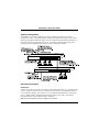
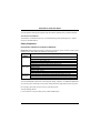
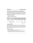
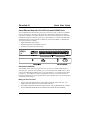
EtherHub-16 Quick Start Guide Smart Ethernet Hub with 16 RJ-45 Ports and AUI/BNC Ports This 10 Mbps Ethernet hub includes 16 RJ-45 ports on the front panel, as well as AUI and BNC ports on the rear panel. This hub can be operated in a stand-alone configuration, cascaded to other hubs, or linked to an AUI/BNC backbone. This hub is suitable for desktop or rack-mount installation, and supports full-range power input. The EtherHub-16 conforms to the IEEE 802.3 standard for local area networks based on CSMA/CD, and provides10BASE-T, 10BASE2 and AUI repeater functions including: • • • Signal amplification and retiming Preamble regeneration and fragment extension Automatic port partition and reconnection Hardware Installation The EtherHub-16 has 16 RJ-45 ports, of which Port 16 can serve as either a standard port or a daisy-chain port. It also has AUI and BNC ports. Use twisted-pair cable (100W STP or UTP) to connect any standard RJ-45 (MDI-X) port to a server/workstation, or to connect the RJ-45 daisychain port (i.e., Port 16MDI) to another compatible hub or switch. You can also attach to an Ethernet LAN backbone by connecting thin coaxial cable to the BNC port or by connecting thick coaxial cable to the AUI port. Making RJ-45 Connections 1. Prepare straight-through twisted-pair cable (100W) with RJ-45 plugs at both ends. The length of each cable should not exceed 100 meters (328 feet). I Do not plug a phone jack connector into any RJ-45 port. This may damage the hub. Instead, use only twisted-pair cables with RJ-45 connectors that conform with FCC standards. 1 EtherHub-16 Quick Start Guide 2. If you are making a connection to an end-node device (e.g., a PC or server), be sure that it has a properly installed 10BASE-T network interface card. Attach one end of a straight-through twisted-pair cable to any standard port (Port 1 ~ 16MDI-X) on the hub and the other end to the RJ-45 port of the other device’s network interface card. When inserting an RJ-45 plug, be sure the tab on the plug clicks into position, to ensure that it is properly seated. Using the hub in a stand-alone configuration, you can network up to 16 workstations. 3. Port 16MDI can be connected to a networking device such as another compatible hub or a switch. Run straight-through cable from Port 16MDI on this hub to a standard (MDI-X) port on the other device. (When attaching the hub to a bridge or router, verify the port type implemented on these devices before connecting any cabling.) Note: If necessary, you may also cascade from the MDI port on another device to the MDI-X port on this hub. Limit the number of hubs cascaded together to four, and be sure you do not create any loops in your network connections. Connecting to an Ethernet Backbone Thin Ethernet - Plug the BNC T-type connector into the BNC port on the hub, and use this port to connect the hub to a 10BASE2 thin Ethernet trunk. If the unit is at the terminal end of a trunk segment, then connect a 50-ohm (Ω) terminator to the open end of the “T” connector. If the BNC port has no connection, plug in the T-type connector and lock both ends with a 50 Ω terminator. Thick Ethernet - Attach an AUI to 10BASE5 transceiver to the thick Ethernet trunk, and then run an AUI drop cable (with 15-pin D-type connectors on both ends) between the AUI port of the hub and the transceiver. Note that the maximum length of an AUI drop cable is 50 meters (164 feet). Fiber Optic - If you plan to use an AUI port for connecting fiber optic cable, attach a fiber optic transceiver (MAU) to an AUI port, and then run fiber optic cable to the remote device. Providing Power to the Hub 1. Power on the hub by plugging the power cord into the power socket at the rear of the hub, and the other end into a power outlet. 2. Check the LED marked Power on the front panel to see if it is on. The unit automatically selects a setting that matches the connected input voltage. Therefore, no additional adjustments are necessary when connecting to any input voltage in the range marked on the rear panel. 2 EtherHub-16 Quick Start Guide System Configuration The EtherHub-16 provides standard RJ-45 ports for attaching end-node devices such as a workstation or server, a daisy-chain port for cascading to another hub or switch, a BNC port for attaching a thin Ethernet backbone, and an AUI port for attaching a thick Ethernet backbone or a fiber optic link (via the appropriate transceiver). The following figure illustrates some of the possible network configurations and cabling restrictions that apply to this hub. Hardware Description RJ-45 Ports This hub has 16 RJ-45 ports that can be used to connect end-node devices (e.g., workstations, file servers, or printers). Be sure you have an Ethernet network interface card installed in the device to be connected to the hub. Then connect it to any available standard RJ-45 port on the hub (i.e., Ports 1~16MDI-X) using straight-through twisted-pair cable (UTP or STP). Note that the maximum length for each twisted-pair cable is 100 meters. Note: When Port 16MDI-X is used, Port 16MDI cannot be used. 3 EtherHub-16 Quick Start Guide Daisy-Chain Port A compatible hub or other network interconnection device (e.g., an Ethernet switch) can be attached to the daisy-chain port (Port 16MDI). Use straight-through twisted-pair cable (STP or UTP) to connect to a standard MDI-X port on the target device. Up to 4 hubs can be cascaded in this manner. To connect to another hub, you may also run twisted-pair cabling from an MDI-X port on this hub to an MDI daisy-chain port on another hub. However, if you must connect to another hub via standard MDI-X ports at both ends of the cable, use crossover cabling. Note: When Port 16MDI is used, Port 16MDI-X cannot be used. BNC Port (10BASE2) This hub has a built-in BNC transceiver on the rear panel for connection using thin coaxial cable. A BNC port can be connected to a thin coaxial cable segment containing up to 30 nodes (i.e., T-type connections). The thin coaxial cable that links the BNC ports may be extended up to 185 meters (607 feet) and have computers or other Ethernet devices attached to it. When connecting two hubs via BNC ports, there should be at least 0.5 meters (1.64 feet) of coaxial cable between the two BNC ports. If the hub is at the end of an Ethernet cable, attach a 50-ohm (Ω) terminator to the open end of the T-type connector on the BNC port. F Close off the open end of any T-type connector that is plugged into a BNC port with a 50-Ω terminator. In particular, when a hub using the BNC port connection is at the end of an Ethernet segment, close off the open end of the T-type connector with a 50Ω terminator. Also, if the BNC port is not used, plug a T-type connector into it and close off both ends with a 50Ω terminator. AUI Port This hub has a built-in AUI transceiver on the rear panel for connection using thick Ethernet cable (10BASE5) or fiber optic Ethernet cable (10BASE-F). An AUI port can be connected to thick Ethernet by running an AUI drop cable from the hub to a 10BASE5 transceiver attached to the trunk line. A thick Ethernet segment can be extended up to 500 meters (1640 feet) and contain up to 100 nodes (i.e., 10BASE-5 connections). For fiber optic connection, attach a transceiver directly to the AUI port, and run a point-to-point link up to 2 kilometers (1.24 miles). 4 EtherHub-16 Quick Start Guide Front Panel Indicators This hub provides LED indicators for monitoring various network conditions. A glance at the front panel allows you to instantly monitor the status of each station port plus the overall condition of the hub. LED Power Link/Traffic Col/Traffic Status Steady Steady Flashing Steady Flashing Indication Power is being supplied to the hub. Port is connected to an active node and receiving a valid Link Integrity pulse. Traffic is passing through this port. Two or more devices are transmitting at the same time. This is normal for an Ethernet network. However, if there are excessive collisions, the network may be overloaded. Traffic is passing through this port. Troubleshooting Symptom: Causes: Solution: Symptom: Causes: Solution: Link/Traffic indicator remains unlit. Workstation’s network adapter, cable or hub port is defective. The most common cause is a defective network adapter or cable connection. Check the corresponding cable connections, or the workstation’s network adapter for possible defects. Verify that the correct cable type (straight or crossover) is being used. (Note that crossover cable is only required if you cascade hubs via standard MDI-X ports; i.e., Port 16MDI is not used.) Replace the defective cable or adapter. Power indicator does not light up after power on. Defective power supply or attached cable, or a problem at the power source. Check the power source and attached cable. If the problem cannot be resolved, you may have to replace your unit’s power supply. Ask for dealer assistance. 5 EtherHub-16 Quick Start Guide Specifications Transmission Technique Topology Access Method Standard Conformance Media Supported Interfaces Hub-to-Workstation Distance DimensionsDimensions Power Input Power Consumption Operating Temperature Humidity Certification Emissions Safety 6 : Baseband : Tree, Star, Bus (BNC/AUI) : CSMA/CD, 10 Mbps : IEEE 802.3 10BASE-T, 10BASE2, AUI : Category 3,4,5 twisted-pair cable : 16 standard MDI-X RJ-45 ports, 1 MDI RJ-45 daisy-chain port, 1 AUI port, 1 BNC port : 100m max. (328 ft) : 320mm x 105mm x 44mm (12.6" x 5.13" x 1.73") : 100-240 (10%) VAC : 1 Amp max. : 0°C to 80°C ( 32°F to 176°F) : 10% to 90% (Noncondensing) : FCC Class A : UL, CSA, TÜV/GS EtherHub-16 Quick Start Guide EMI Warning FCC Class A Certification This device complies with Part 15 of the FCC Rules. Operation is subject to the following conditions: 1. This device may not cause harmful interference, and 2. This device must accept any interference received, including interference that may cause undesired operation. Warning: This equipment generates, uses, and can radiate radio frequency energy and, if not installed and used in accordance with the instruction manual, may cause interference to radio communications. It has been tested and found to comply with the limits for a Class A digital device pursuant to Subpart B of Part 15 of FCC Rules, which are designed to provide reasonable protection against such interference when operated in a commercial environment. Operation of this equipment in a residential area is likely to cause interference, in which case the user, at his own expense, will be required to take whatever measures are required to correct the interference. You may use unshielded or shielded twisted-pair (100Ω STP or UTP) for RJ-45 connections. Warnings 1. Wear an anti-static wrist strap or take other suitable measures to prevent electrostatic discharge whenever handling this equipment. 2. When connecting this hub to a power outlet, connect the field ground lead on the tripole power plug to a valid earth ground line to prevent electrical hazards. 3. The connectors are not for telephone system use. Les raccordeurs ne sont pas utilisé pour le système téléphonique! Note: In order to maintain compliance with the limits of a Class A digital device, Accton requires that you use a quality interface cable when connecting to this device. Changes or modifications not expressly approved by Accton could void the user’s authority to operate this equipment. Suggested cable type is: Twisted-pair for RJ-45 connections: 10BASE-T Thin Ethernet (50 ohm) for BNC connections: 10BASE2 Thick Ethernet (D-type) for AUI connections: 10BASE5 Fiber optic cable that meets requirements of external transceiver: 10BASE-F 7 EtherHub-16 Quick Start Guide You may find the following book prepared by the Federal Communication Commision helpful: The Interference Handbook This booklet is available from the U.S. Government Printing Office. Washington, D.C. 20402. Stock No. 004-000-00345-4. Safety Compliance Underwriters Laboratories Compliance Statement Important! Before making connections, make sure you have the correct Cord Set. Check it (read the label on the cable) against the following specification list. Operating Voltage 120 Volts 240 Volts (For North America) 240 Volts (For Europe only) Cord Set Specifications UL Listed/CSA Certified Cord Set Minimum 18 AWG Type SVT or SJT three conductor cord Maximum length of 15 feet Parallel blade, grounding type attachment plug rated 15A, 125V UL Listed/CSA Certified Cord Set Minimum 18 AWG Type SVT or SJT three conductor cord Maximum length of 15 feet Tandem blade, grounding type attachment plug rated 15A, 125V Cord Set with H05VV-F cord having three conductors with minimum diameter of 0.75 mm2 IEC-320 receptacle Male plug rated 6A, 250V The unit automatically matches the connected input voltage. Therefore, no additional adjustments are necessary when connecting it to any input voltage within the range marked on the rear panel. Do not plug a phone jack connector into any of the RJ-45 ports. This may damage the hub. Les raccordeurs ne sont pas utilisé pour le système téléphonique! 8 EtherHub-16 Quick Start Guide Sicherheitshinweise 1. Die Steckdose muß sich in der Nähe des Gerätes befinden und leicht zugänglich sein. 2. Zum Reinigen den Stecker aus der Steckdose ziehen. Beim Reinigen keine Flüssigreiniger oder Sprays verwenden, sondern ein angefeuchtetes Tuch. 3. Das Ethernet hub gerät nicht in Naßräume oder in der Nähe von Wasser benutzen, wie z.B. Badezimmer, Schwimmbad, Spülbecken usw. . Das Eindringen von Wasser kann zur Zerstörung des Gerätes führen. 4. Das Ethernet hub gerät nicht auf einer unstabilen Unterlage, wie z.B. Rollwagen, Gestell usw., aufstellen. Es könnte herunterfallen und Verletzungen oder Beschädigungen von Mensch und Gerät verursachen. 5. Die Belüftungsöffnungen nicht blockieren oder auf falscher Ober-fläche, wie Bett, Sofa usw., stellen. Durch die Blockierung kann es zur Zersörung des Gerätes durch Überhitzung kommen. 6. Versuchen Sie niemals dieses Gerät selbst zu warten, da beim Öffnen oder Abnehmen des Gehäuses die Gefahr eines elektrischen Schlages besteht. 7. Keine Gegenstände auf das Anschlußkabel stellen, damit es nicht durch scharfe Kanten zerstört werden kann. 8. Keinerlei Gegenstände durch die Öffungen in das Gerät stecken, da es dadurch sonst zu Kurzschlüssen kommen kann. 9. Bei Störungen des Gerätes den Wartungsdienst verständigen. 10. Bei Reperaturen dürfen nur Orginalersatzteile oder Bauteile mit gleichen Eigenschaften verwendet werden. Andere Bauteile können Feuer, elektrischen Schlag oder andere Gefahren verursachen. 11. Nach Beendigung von Wartungsarbeiten oder Reperaturen durch den Kundendienst sollte die Sicherheitsprüfung durchgeführt werden. 12. Bei längerem Stillstand des Gerätes, ist diese von der Versorgungs- spannung zu trennen. Dies verhindert eine Beschädigung des Gerätes durch eine Überspannung in der Zuleitung. 13. Der arbeitsplatzbezogene Lärmschutzpegel nach DIN 45 635 ist kleiner 70dB (A). 9 EtherHub-16 Quick Start Guide Warranty Accton warrants to the original owner that the product delivered in this package will be free from defects in material and workmanship for the lifetime of the product. For the warranty to apply, you must register your purchase by returning the registration card indicating the date of purchase and including proof of purchase. There will be a minimal charge to replace consumable components, such as fuses, power transformers, and mechanical cooling devices. The warranty does not cover the product if it is damaged in the process of being installed. Accton recommends that you have the company from whom you purchased this product install it. THE ABOVE WARRANTY IS IN LIEU OF ANY OTHER WARRANTY, WHETHER EXPRESS, IMPLIED OR STATUTORY, INCLUDING BUT NOT LIMITED TO ANY WARRANTY OF MERCHANTABILITY, FITNESS FOR A PARTICULAR PURPOSE, OR ANY WARRANTY ARISING OUT OF ANY PROPOSAL, SPECIFICATION OR SAMPLE. ACCTON SHALL NOT BE LIABLE FOR INCIDENTAL OR CONSEQUENTIAL DAMAGES. ACCTON NEITHER ASSUMES NOR AUTHORIZES ANY PERSON TO ASSUME FOR IT ANY OTHER LIABILITY. Copyright Copyright 1997 by Accton Technology Corporation. All rights reserved. Product specification are subject to change without notice. All trademarks or brand names are properties of their respective companies. Disclaimer The publisher assumes no responsibility for errors that may appear in this document, nor does it make any commitment to update information it contains. All brand and product names mentioned are trademarks or registered trademarks of their respective companies. For warranty information: All territories except North and South America: Accton Technology Corporation, International Headquarters No. 1, Creation Rd. III, Science-based Industrial Park, Hsinchu 300, Taiwan, R.O.C. Phone: 886-3-5770-270 Fax: 886-3-5770-267 BBS: 886-3-5770-654 North and South America: Accton Technology Corporation, USA Headquarters 1962 Zanker Road, San Jose, CA 95112, U.S.A. Phone: 408-452-8900 Fax: 408-452-8988 BBS: 408-452-8828 EH2016A E0697-R01 10