1
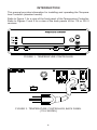
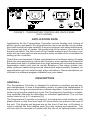
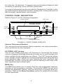
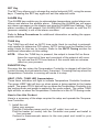
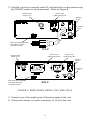
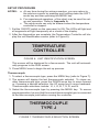
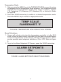
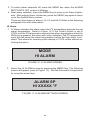
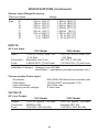
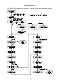
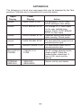
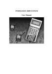
Digi –Sense ®
INSTRUCTION MANUAL
Temperature Controller R/S
(Standard Model)
68900-01
68900-03
Eutech Instruments Pte Ltd
Blk 55 Ayer Rajah Crescent
#04-16 Singapore 139949
Tel: (65) 6778 6876
Fax: (65) 6773 0836
Website: www.eutechinst.com
email: [email protected]
68X329501 Rev.1 02/04
TABLE OF CONTENTS
Title
Page
SAFETY PRECAUTIONS ...................................................................... 1
INTRODUCTION .................................................................................... 2
APPLICATION DATA .............................................................................. 3
DESCRIPTION ....................................................................................... 3
GENERAL ......................................................................................... 3
CONTROL PANEL DESCRIPTION .................................................. 4
Vacuum Fluorescent Readout ...................................................... 4
UP, DOWN, LEFT Arrows ............................................................ 4
MENU Key ................................................................................... 4
SET Key ....................................................................................... 5
ALARM Key .................................................................................. 5
TUNE Key .................................................................................... 5
RUN/STOP Key ............................................................................ 5
HEAT, COOL, TUNE LED Annunciators ...................................... 5
How To Use This Product ............................................................. 5
INSTALLATION ...................................................................................... 6
INITIAL HARDWARE SETUP ........................................................... 6
SETUP PROCEDURE ...................................................................... 8
Thermocouple .............................................................................. 8
Temperature Scale ....................................................................... 9
Alarm Selections .......................................................................... 9
HI Alarm ................................................................................ 10
LO Alarm .............................................................................. 11
HILO Alarm ........................................................................... 11
Alarm Hysteresis ................................................................... 12
Audible Alarms ........................................................................... 13
Advanced Set-Up ....................................................................... 13
Sensor Calibrate ........................................................................ 13
Over Temp Stop ......................................................................... 14
Loop Break Stop ........................................................................ 14
Control Action ............................................................................ 15
Control Mode ............................................................................. 15
Control Mode On/Off ............................................................. 16
PID - Proportional Band, Integral and Derivative .................. 16
AUTO Tune ........................................................................... 16
Proportional Band ............................................................ 17
Integral Time .................................................................... 17
Derivative Rate ................................................................ 18
i
TABLE OF CONTENTS (Continued)
Title
Page
Cycle Time ................................................................................. 18
Run Time .................................................................................... 18
Power Up Control ....................................................................... 19
OPERATION ........................................................................................ 20
RUN MODE ..................................................................................... 20
TROUBLESHOOTING AND MAINTENANCE ..................................... 21
TROUBLESHOOTING .................................................................... 21
CALIBRATION ................................................................................ 21
MAINTENANCE/CLEANING ........................................................... 21
SPECIFICATIONS ............................................................................... 22
INPUTS ........................................................................................... 23
OUTPUTS ....................................................................................... 23
WARRANTY ......................................................................................... 24
PRODUCT RETURN ............................................................................ 24
TECHNICAL ASSISTANCE ................................................................. 24
APPENDIX A - SETUP MODE .......................................................... A-1
APPENDIX B - ERROR MESSAGES/CORRECTIVE ACTION ......... B-1
ACCESSORIES ................................................................... BACK PAGE
ii
SAFETY PRECAUTIONS
DANGER:
There are no user-serviceable parts in this instrument. Do not remove cover, as high voltages exist
inside the unit. Refer servicing to your dealer.
DANGER:
If thermocouples are at a high voltage, this voltage
will be present at other points inside the unit.
DANGER:
For continued fire protection, replace fuse only with
a fuse of the specified current, voltage, and type.
Remove power cord from wall socket before checking or replacing a fuse. High voltages exist on fuse
terminals.
WARNING: To avoid electric shock, the power cord protective
grounding conductor must be connected to earthground.
WARNING: Install an independent temperature limit control protection system where a fault condition could result
in fire or other hazard. Failure to install such a system could result in injury to personnel or damage to
property.
Trademarks bearing the ® symbol in this publication are registered in the U.S. and in other countries.
1
INTRODUCTION
This manual provides information for installing and operating the Temperature Controller (standard model).
Refer to Figure 1 for a view of the front panel of the Temperature Controller.
Refer to Figures 2 and 3 for a view of the back panels of the 115 or 230 V
versions.
FIGURE 1. TEMPERATURE CONTROLLER
FIGURE 2. TEMPERATURE CONTROLLER, BACK PANEL
(115 V MODEL)
2
FIGURE 3. TEMPERATURE CONTROLLER, BACK PANEL
(230 V MODEL)
APPLICATION DATA
Applications for the Temperature Controller include heating and cooling of
solids, liquids, and gases. For all applications, there are certain set-up operations that should be made carefully to assure optimum and safe performance.
The power and type of heater, the positioning of the sensor, the amount of
thermal insulation, the flash point of the heated material and the many controller set-up menu options are among the many variables to be considered in
setting up the controller.
One of the most important of these considerations is the heater sizing. A heater
that is too low powered may not be able to raise or even maintain the material at
the desired set point. A heater that is too high powered will not maintain precise
temperature control and may be unsafe. Because of the many system variables, optimum heater sizing must be determined experimentally; however, an
approximation can be made through a few calculations. These calculations are
included in a software program available from your dealer.
DESCRIPTION
GENERAL
The Temperature Controller is designed to maintain a constant, pre-set process temperature. It uses a temperature sensor to detect the temperature of
the process. Using a microprocessor software algorithm, it adjusts a heater or
cooler by varying the output duty cycle. The Temperature Controller is a singleloop controller intended for laboratory or industrial applications. The unit can
control loads of up to 10 amperes (A).
The Temperature Controller is housed in a rectangular metal enclosure, with
plastic bezels on the front and back. All connections are made on the rear of
the unit. The display and keypad are on the front. A bail bar, or tilt stand, is
used to elevate the front display panel for easy viewing and operation. The
unit can also be mounted in a panel with the use of an optional panel mount
3
kit. A two-line, 16-character, 14-segment vacuum fluorescent display is used
for display of operating, setup, and alarm parameters.
A number of accessories can be used with this Temperature Controller, including various types of temperature sensors, heating units, cooling units (such as
fans or pumps), remote alarms, and recorders.
CONTROL PANEL DESCRIPTION
Refer to Figure 4 and the following paragraphs.
Readout Display
LEFT Arrow
UP and
DOWN
Arrows
Indicator
Lights
Alarm LED
Function Control Keys
FIGURE 4. FRONT PANEL DISPLAYS
Vacuum Fluorescent Readout
The vacuum fluorescent readout displays operation and setup parameters.
Alarm conditions are also displayed.
UP, DOWN, LEFT Arrows
The UP and DOWN arrow keys will increment or decrement the current
values of displayed (blinking) numerals or enable you to scroll through a list
where multiple-choice parameters are offered. The LEFT arrow key allows
you to change numeric settings by moving the blinking cursor left to the next
most significant digit. When you have reached the most significant digit
(furthest left), the LEFT arrow key will move the flashing cursor back to the
least significant digit (furthest right).
MENU Key
The MENU key allows you to access all of the user-configurable setup parameters of the temperature controller. Pressing the MENU key will scroll
through the parameter options, using the arrow keys to change those parameters. Refer to the Setup Procedure section for additional information
on each parameter.
4
SET Key
The SET key allows you to change the control setpoint (SP), using the arrow
keys. Pressing the SET key again will exit the setpoint mode.
ALARM Key
The ALARM key enables you to acknowledge temperature control alarm conditions and silence the audible alarm. Pressing the ALARM key will erase
any alarm messages on the display and stop the ALARM from flashing. If the
alarm condition is still present, the ALARM LED will remain on until the PV
(process variable) is out of the alarm condition.
Refer to Setup Procedures for additional information on setting the appropriate alarms.
TUNE Key
The TUNE key will start an AUTO tune cycle. Heat (or cooling) is automatically applied to determine PID values. AUTO tuning must be enabled in the
setup mode for this key to function. Refer to the AUTO Tuning section for
additional information on this setting.
NOTE: When the TUNE key is pressed, the output is turned full on three
times for a period of time and overshoot of the setpoint will occur.
Do not use the AUTO tune feature if this would have an adverse
affect on your process.
RUN/STOP Key
Pressing this key when the Temperature Controller is stopped will start the
control process and activate the load, if required. Pressing this key when the
Temperature Controller is running will cause it to stop.
HEAT, COOL, TUNE LED Annunciators
These three indicators will light to indicate Temperature Controller functions.
The green HEAT light will turn on when power is being applied to the heater
output. The green COOL light will turn on when the Temperature Controller is in
the cooling mode and power is applied to the cooler output. The yellow TUNE
light will turn on when the Temperature Controller is in the AUTO tuning mode.
How to Use this Product
Here is a summary of the steps required to setup and operate the Temperature Controller.
1. Install the unit.
Setup your process.
Plug the Controller power cord to an AC outlet, turn unit on.
Plug the heater (or cooler) into the Controller rear panel and install in
your process.
Connect a thermocouple sensor to the rear panel and install in your
process.
5
2. Setup the operating parameters. Press MENU and follow the interactive
setup selections. If your setup is the same as the factory set defaults,
this step is not necessary. However, each of the setup options should be
checked for desired or proper setting.
Set sensor type that was connected.
Select temperature scale.
Set alarms, if desired.
Calibrate system, if better accuracy is desired.
Set safety stops (over temperature and loop break).
Select control action and mode desired (PID or on/off).
Set max. run time.
3. Set the run temperature and begin controlling.
Press the SET key and enter the desired setpoint temperature.
Press TUNE if autotune is selected in setup and you want to automatically determine the PID settings.
Press the RUN/STOP key to begin temperature control.
The setpoint (SP) temperature and the actual temperature (or process
variable, PV) are displayed.
Press ALARM to acknowledge an alarm condition.
INSTALLATION
INITIAL HARDWARE SETUP
1. Remove controller from packaging. Keep all packing material until proper
operation has been verified.
2. Use the "bail" bar (or tilt-stand) at the bottom of the unit to adjust position
for easy viewing of front panel.
WARNING:
To avoid electric shock, the power cord protective grounding conductor must be connected to earth-ground.
WARNING:
Install an independent temperature limit control protection system where a fault condition
could result in fire or other hazard. Failure to
install such a system could result in injury to
personnel or damage to property.
6
3. Plug the unit in to a correctly rated AC outlet and turn on the power using
the ON/OFF switch on the back panel. Refer to Figure 5.
Heater Cord
Cable Connection
Heater/Cooler
Output Fuse
ON/OFF
Switch
Instrument
Fuse
Mini-ANSI Thermocouple
Jack (500 ohm Max
Load Resistance)
115 V
Heater Cord
Cable Connection
Heater/Cooler
Output Fuse
Power Line
Cord Connection
ON/OFF
Switch
Instrument
Fuse
Mini-ANSI Thermocouple
Jack (500 ohm Max
Load Resistance)
230 V
FIGURE 5. BACK PANEL VIEWS (115 V AND 230 V)
4. Connect one of the eight types of thermocouples to the unit.
5. Connect the heater or cooler (maximum of 10 A) to the unit.
7
SETUP PROCEDURE
NOTES:
a. At any time during the setup procedure, you may return to
the previous screen by pressing and holding down the LEFT
arrow key and then pressing the MENU key.
b. For experienced operators, a flow chart may be used for setup and operation. Refer to Appendix A.
c. The setup mode can only be entered when the temperature
controller is stopped.
1. Set the ON/OFF switch on the rear panel to ON. The LEDs will light and
all segments will light temporarily as a check of the display.
2. After the diagnostics are complete, the Temperature Controller will display the unit identification screen (refer to Figure 6).
TEMPERATURE
CONTROLLER
FIGURE 6. UNIT IDENTIFICATION SCREEN
This screen will be displayed for a few seconds. The unit will automatically progress to the RUN screen.
3. Press MENU once to begin the set up process.
Thermocouple
1. To select a thermocouple type, press the MENU key (refer to Figure 7).
2. The screen will display the last thermocouple selected. To chose another thermocouple type, press the DOWN arrow key to move forward
or, if passing a desired selection, the UP arrow key to move backward.
Thermocouple selections include: K, J, E, B, T, S, R, and N.
3. Select the thermocouple type by pressing the MENU key. To ensure
proper operation, be sure that the correct thermocouple type is connected
at the thermocouple jack before running the controller.
THERMOCOUPLE
TYPE J
FIGURE 7. THERMOCOUPLE SELECTION SCREEN
8
Temperature Scale
1. After pressing the MENU key in the THERMOCOUPLE screen, the setup
will progress to the Temperature Scale selection. The Temperature scale
selection has five temperature scales from which to choose: Celsius
(°C), Fahrenheit (°F), Reaumur (°R'), Rankine (°R), or Kelvin (K). Refer
to Figure 8.
2. Press the DOWN arrow key to switch to a desired temperature scale.
Press the MENU key to select the appropriate scale.
TEMP SCALE
FAHRENHEIT °F
FIGURE 8. TEMPERATURE SCALE SELECTION SCREEN
Alarm Selections
1. Alarms will activate only when the temperature controller is in the RUN
mode. When an alarm occurs, the alarm LED will flash, the audible alarm
will sound intermittently and the display will flash the type of alarm. There
are two possible alarm setpoints selections: ON or OFF. Refer to Figure
9.
2. To go to the Alarm Setpoints Off Screen, press the DOWN arrow key.
ALARM SETPOINTS
ON
FIGURE 9. ALARM SETPOINTS SELECTION SCREEN
9
3. To select alarm setpoints off, press the MENU key when the ALARM
SETPOINTS OFF screen is blinking.
4. After alarm selection, press the MENU key to move on to Alarm Hysteresis. After setting Alarm Hysteresis, press the MENU key again to move
on to the Audible Alarm screen.
There are three types of alarms: HI, LO and HILO. Refer to the following
paragraphs for more information.
HI Alarm
1. HI Alarm activates the alarm when the PV temperature exceeds the set
alarm temperature. Refer to Figure 10. If the Control Action is set to
COOL and the PV temperature exceeds the alarm temperature when the
RUN key is pressed, the alarm will not be activated. The PV temperature
must first fall below the alarm temperature before the high alarm is enabled. This allows for normal system startup in COOL mode without activating the alarm.
MODE
HI ALARM
FIGURE 10. HI ALARM SCREEN
2.
Select the HI ALARM screen by pressing the MENU key. The following
screen will appear (refer to Figure 11). Set the Process HI temperature
by using the arrow keys.
ALARM SP
HI XXXXX °F
FIGURE 11. HI ALARM SETTINGS SCREEN
10
LO Alarm
1. LO Alarm activates the alarm when the PV temperature drops below the
alarm temperature. Refer to Figure 12. If the Control Action is set to
HEAT and the PV temperature is below the alarm temperature when the
RUN Key is pressed, the alarm will not be activated. The PV temperature must first rise above the alarm temperature before the low alarm is
enabled. This allows for normal system startup without activating the
alarm.
MODE
LO ALARM
FIGURE 12. LO ALARM MODE SCREEN
2. Select the LO Alarm screen by pressing the MENU key. The following
screen will appear (refer to Figure 13). Set the Process LO temperature
by using the arrow keys.
ALARM SP
LO 000XX °F
FIGURE 13. LO ALARM SETTINGS SCREEN
HILO Alarm
1. HILO Alarm allows both a HI Alarm and LO Alarm to be set. Refer to the
HI Alarm and LO Alarm sections for a detailed description of the operation of each alarm. Refer to Figure 14.
MODE
HILO ALARM
FIGURE 14. HILO ALARM SCREEN
11
2. Select HILO by pressing the MENU key. The following screen will appear
(refer to Figure 15). Set the alarm temperatures by using the arrow keys.
Once the first alarm value is set, press the LEFT arrow key to adjust for
the other alarm variable.
ALARM SP °F
HI XXXX.X LO XXXX.X
FIGURE 15. HILO SETTINGS SCREEN
Alarm Hysteresis
1. Alarm Hysteresis determines when the alarm is going to be out of the
alarm condition. Alarm hysteresis prevents actuation of nuisance, or
recurrent, alarms. Hysteresis is either added or subtracted to the alarm
point, depending on whether a HI or LO ALARM has been set.
For example: If hysteresis is set at 1 degree and the HI alarm has been
set to trigger when the temperature reaches 100 degrees FAHRENHEIT,
the alarm will trigger at 100 degrees. As soon as the temperature drops
below 99 degrees the alarm condition will terminate.
ALARM HYSTERESIS
XXX.X °F
FIGURE 16. ALARM HYSTERESIS SCREEN
2. Set the hysteresis by using the arrow keys.
3. After selecting values, press the MENU key to continue.
12
Audible Alarms
Audible Alarm permits the sound of an alarm. It has two options: On or Off.
Use the arrow keys to select an option and press the MENU key to advance
to the Advanced Setup MENU. Refer to Figure 17.
AUDIBLE ALARM
ON
FIGURE 17. ALARM AUDIBLE SCREEN
Advanced Set-Up
1. After pressing the MENU button, the ENTER ADVANCED SETUP screen
will be displayed (refer to Figure 18).
2. The flashing message YES will ask if you want to enter the Advanced
Screen. Press the MENU key as the word YES blinks.
NOTE: If a change to that selection is not chosen within 3 seconds, the
program will automatically exit the setup mode.
ENTER ADVANCED
SETUP MENU YES
FIGURE 18. ADVANCED SETUP SCREEN
Sensor Calibrate
1. Sensor Calibrate enables the operator to calibrate out sensor error
to give a more accurate reading. Refer to Figure 19. Calibration
offset and PV (actual) temperatures are displayed.
2. To adjust the values in this option, the operator must know how
many degrees off the sensor is. To determine how far off the sensor
is, measure it against a secondary gauge known to be accurate.
3. Once the value is known, adjust the CAL offset value on the screen
using the arrow keys until the displayed temperature matches the
known temperature. Press the MENU key to advance to the Over
temp screen. (Refer to Figure 20.)
13
SENSOR OFFSET
CAL ± XX.X XXX.X °F
FIGURE 19. SENSOR OFFSET CAL
NOTE: Calibration can also be done using an ice bath or boiling water
and adjusting the offset until 32.0 °F or 212 °F is displayed.
Over Temp Stop
1. Over temp stop temperature, a safety feature, is added to the setpoint
(SP) temperature. If the PV temperature exceeds this amount, the temperature controller will stop. Over temp stop does not operate if the
COOL control action is selected. Refer to Figure 20.
OVER TEMP. STOP
XX °F ABOVE SP
FIGURE 20. OVERTEMP SCREEN
2. To change the Overtemp value, use the arrow keys. After the value has
been set, press the MENU key to advance to the Loop Break Stop Screen.
Loop Break Stop
Loop break stop, a safety feature, is designed to stop the temperature
controller if the heater output is on for the amount of time set in Loop Break
Stop and the PV temperature does not increase more than 1.0 °F. If the
COOL control action is selected, it is stopped if the PV temperature does not
decrease more than 1.0°F. Refer to Figure 21.
LOOP BREAK STOP
XXX.X MINUTES
FIGURE 21. LOOP BREAK STOP SCREEN
14
Loop break stop is designed to terminate the process currently running if the
process is interrupted for a preset period of time. The loop break stop senses
that nothing is happening in the process and turns the process off.
Enter an elapsed time using the UP and DOWN arrow keys. For slow systems, a longer time should be entered.
Control Action
1. The Control Action screen allows selection of the type of process that will
be performed; either HEAT or COOL. Refer to Figure 22. In the heat
mode, the output is on when the actual temperature is below the setpoint
temperature (inverse action). In the cool mode, the output is on when the
actual temperature is above the setpoint temperature (direct action).
CONTROL ACTION
HEAT
FIGURE 22. CONTROL ACTION SCREEN
2. The default setting is HEAT. Use the DOWN arrow key to select either
heat or cool actions. Press the MENU key to enter your selection.
Control Mode
1. The Control screen has two options: PID (proportional band, integral
and derivative), and ON/OFF. Refer to Figure 23.
CONTROL MODE
PID
FIGURE 23. CONTROL SCREEN
2. Select one of these options using the arrow keys. When the desired
option appears on the screen, press the MENU key. Refer to the PID
procedural paragraphs, following, for additional information.
15
Control Mode On/Off
1. The Control Mode On/Off turns off the output when the actual temperature exceeds the setpoint (heat control action). The output will turn on
when the actual temperature falls below the setpoint temperature minus
the hysteresis temperature. Refer to Figure 24.
ON/OFF CONTROL
HYSTERESIS XX.X °F
FIGURE 24. ON/OFF CONTROL HYSTERESIS SCREEN
2. Adjust the hysteresis value on this screen using the arrow keys.
3. Press the MENU key to advance to the RUN TIME Screen.
PID - Proportional Band, Integral and Derivative
PID is the means of selecting the response speed or sensitivity of a proportioned controller to achieve stability in the system. It should be used when
system stability or accuracy requirements are too great for use of on/off control.
AUTO Tune
1. After selecting the PID screen the next screen to appear will be AUTO
TUNE. Refer to Figure 25. Two choices are available for this selection:
AUTO TUNE ENABLED and AUTO TUNE DISABLED. The recommended
choice for this screen is AUTO TUNE ENABLED.
The default setting is ENABLED. Use the DOWN arrow key to select
either enabled or disabled. Press the MENU key to enter your selection.
NOTE: When AUTO TUNE DISABLED is selected, auto tuning cannot be
initiated using the TUNE key on the front panel.
AUTO TUNE
ENABLED
FIGURE 25. AUTO TUNE SCREEN
16
2. Select an option using the arrow keys.
3. If AUTO TUNE ENABLED is selected, press the MENU key four times to
advance past the PID setup to the Cycle Time screen.
NOTE: AUTO TUNE DISABLED is also a safety feature to prevent
accidental auto tuning.
Proportional Band
1. Select the proportional band by pressing the MENU key. The following
screen will appear (refer to Figure 26).
2. Use the arrow keys to enter the correct value and press the MENU key.
PROPORTIONAL
BAND XXXX °F
FIGURE 26. PROPORTIONAL BAND SCREEN
Integral Time
1. Integral time, measured in seconds per repeat, is tuned to correct for the
droop (difference between setpoint and steady state actual temperatures)
that is caused by the proportional output. Refer to Figure 27.
2. Use the arrow keys to enter the correct value and press the MENU key.
INTEGRAL TIME
XXXX SECONDS
FIGURE 27. INTEGRAL SCREEN
17
Derivative Rate
1. The derivative rate reduces or eliminates overshoot. Refer to Figure 28.
It is measured in seconds and must be tuned to work with the overall
system cycle time.
DERIVATIVE RATE
XXXX SECONDS
FIGURE 28. DERIVATIVE SCREEN
2. Use the arrow keys to enter the correct value and press the MENU key.
Cycle Time
Cycle time is the rate at which the output is cycled or changed. The
manufacturer's recommended cycle time is 1 second. If using a mechanical
relay in the process, it is recommended to increase the cycle time to reduce
the number of cycles a relay would have to endure. Refer to Figure 29.
CYCLE TIME
XXXX SECONDS
FIGURE 29. CYCLE TIME SCREEN
1. Use the DOWN arrow key to increment the time period desired.
2. Press the MENU key to advance to the Run Time screen.
Run Time
Run Time is a safety feature that sets the Temperature Controller operating
time. When the set value is reached, the output is turned off. To disable this
feature, select CONTINUOUS by entering a run time of HR00 MIN00. Refer
to Figure 30.
RUN TIME
HR XX MIN XX
FIGURE 30. RUN TIME SCREEN
18
1. Use the DOWN arrow key to increment the time period desired.
2. Press the MENU key to enter your selection.
Power Up Control
This set up option allows you to specify one of two conditions for the temperature controller at turn on. Power Up Control has two options: Last State
and Stopped. Refer to Figure 31.
POWER UP CONTROL
LAST STATE
FIGURE 31. POWER UP CONTROL SCREEN
The two selections are designed primarily to function in the event of a power
failure. If a power outage occurs, Last State will start the process from where
it last ended when the power went out, stopped will leave the process off.
When a run time has been entered it will always power-up in the STOPPED
mode.
1. Use the arrow keys to select one of the options and press the MENU key
to advance to the ADVANCED SET UP COMPLETE screen.
2. Once at this screen, the unit will automatically default to a message screen
which says SAVING SETUP. Setup is complete, and the operation screen
will be displayed.
19
OPERATION
Once installation and setup are complete, press the RUN/STOP key to begin
operation. The following screen will appear (refer to Figure 32) if a previous
run was stopped before it completed.
RUN OPTION
CONTINUE/RESTART
FIGURE 32. RUN SCREEN
Select either CONTINUE or RESTART using the arrow keys and then press
RUN/STOP key. CONTINUE will start a run with the time remaining from the
previous run. RESTART will reset the run time and start a new run. The
information displayed during the RUN mode will depend on the setup options
selected. General display functions for each mode are shown below. Depending on the ALARM options set, alarm conditions will be displayed and
alarms will sound.
RUN MODE
If you selected a run time during setup, the following screen will appear when
running. Refer to Figure 33. Press SET to enter desired setpoint temperature.
PV XX.X °F
SP XX.X
XX_XX_XX
FIGURE 33. DISPLAY OF PROCESS
VARIABLES/SETPOINT IN RUN MODE - ON
The display shows the PV (process variable), the SP (setpoint), and the time
remaining. Time remaining will not appear if CONTINUOUS is selected for
RUN TIME.
20
TROUBLESHOOTING AND MAINTENANCE
DANGER:
There are no user-serviceable parts in this
instrument. Do not remove cover, as high voltages exist inside the unit. Refer servicing to
your dealer.
DANGER:
If thermocouples are at a high voltage, this
voltage will be present at other points inside
the unit.
TROUBLESHOOTING
If the heater output does not function correctly, check the fuse located on the
rear of the unit left of the heater output receptacle. The fuse is rated at 10 A.
Replace it with a fuse having identical voltage and current ratings.
DANGER:
For continued fire protection, replace fuse only
with a fuse of the specified current, voltage,
and type. Remove power cord from wall socket
before checking or replacing a fuse. High voltages exist on fuse terminals.
If the unit does not have power, check the fuse located below the ON/OFF
switch. The fuse is rated at 0.3 A for 115 V applications and 0.6 A for 230 V
applications. Replace this fuse with a fuse having identical voltage and current ratings.
CALIBRATION
System calibration is described in the setup portion of this manual. Instrument calibration is completed at the factory. No user calibration is required to
meet stated specifications.
MAINTENANCE/CLEANING
Maintenance is limited to fuse replacement. All materials withstand standard
cleaning solvents.
21
SPECIFICATIONS
Display:
Two lines of 16 characters. Four-digit
process value. Four-digit setpoint
value.
Accuracy:
Type J,K,T,E and N
above −100°C (−148°F): ±0.1% reading, ±0.4°C (±0.7°F)
below −100°C (−148°F): ±0.1% reading, ±1°C (±1.8°F)
Type R,S and B
±0.1% reading, ±1°C (±1.8°F)
Resolution:
Environment:
Temperature, Operating:
Temperature, Storage:
Temperature, Specification:
Humidity:
Altitude:
Pollution Degree:
0.1° auto-ranging to 1° above 999.9
0 to 40°C
−20 to 70°C
18 to 28°C
10 to 90% RH (non-condensing)
less than 2000 m
Pollution degree 2 per IEC 664
(Indoor Usage—lab, office)
Warm-Up time:
10 minutes
Construction:
Dimensions:
Weight:
Enclosure:
W:7.3 in H:3.7 in D:10.0 in
5.3 lbs.
IP52 per IEC 529
Compliance:
115V and 230V:
230V (For CE mark):
UL 916
EN61010-1/A2:1995 and
EN61010-2-010:1995
(EU Low Voltage Directive) and
EN61326-1/A1:1998
(EU EMC Directive)
22
SPECIFICATIONS (Continued)
Sensor Input Range/Accuracy:
Thermocouples
Type
Range
−200 to 1000°C
−190 to 1000°C
−200 to 1372°C
−200 to 1300°C
−200 to 400°C
200 to 1800°C
0 to 1768°C
0 to 1768°C
E:
J:
K:
N:
T:
B:
R:
S:
(−328 to 1832°F)
(−310 to 1832°F)
(−328 to 2502°F)
(−328 to 2372°F)
(−328 to 752°F)
(−392 to 3272°F)
(− 32 to 3214°F)
(− 32 to 3214°F)
INPUTS
AC Line Input
115V Model
Input:
Connector:
Fuse:
230V Model
115V AC ±15%, 49/61 Hz
10A Max
Standard Line Cord
0.630A/230V (T) 5x20mm
230V AC ±15%, 49/61 Hz
10A Max
IEC 320 C-20 Inlet
0.315A/230V (T) 5x20 mm
Installation Category: Category II per IEC664
(Local level — appliances, portable equipment, etc.)
Thermocouple Probe Input
Connector:
Calibration:
Lead resistance:
Common mode voltage:
Mini-ANSI flat blade thermocouple jack
ITS-90 (NIST monograph 175)
500 Ohm max
5 Volts max
OUTPUTS
AC Line Output
115V Model
Output:
Connector:
Fuse:
230V Model
115V AC typical, 10A max
NEMA 5-15R
10A/230V 3AG Slo-Blo
23
230V AC typical, 10A max
Reverse IEC 320
10A/230V 3AG Slo-Blo
WARRANTY
Eutech Instruments supplies this product with a ONE-YEAR warranty to be
free from significant deviations from published specifications. If repair or
adjustment is necessary within the warranty period, the problem will be corrected
at no charge if it is not due to misuse or abuse on your part as determined
by Eutech Instruments. Repair costs outside the warranty period, or those
resulting from product misuse or abuse,may be invoiced to you.
PRODUCT RETURN
Authorization must be obtained from our Customer Service Department or authorized
distributor before returning items for any reason. A "Return Goods Authorization" (RGA) form
is available through our authorized distributor. Please include data regarding the reason the
returned. For your protection, items must be carefully packed to prevent damage resulting from
careless or insufficient packing. A restocking charge will be made on all authorized returns.
TECHNICAL ASSISTANCE
If you have any questions about the use of this product, contact the nearest
distributor or Eutech Instruments.
24
APPENDIX A
EN 400 Temperature Controller - Setup Mode for Standard Model
25
A-1
APPENDIX B
The following is a list of error messages that may be displayed by the Temperature Controller and a description of corrective action.
Upper
Display
Lower
Display
Action
normal
OVER TEMP STOP
PV exceeded OVER TEMP
STOP setting in user setup.
normal
LOOP BREAK STOP
No change in PV with output
on for user settable time
period. Adjust LOOP BREAK
STOP in user setup.
normal
OPEN PROBE STOP
Detected open probe sensor
while running. Check probe.
normal
OVER PROBE STOP
PV exceeded the upper limit of
selected probe type.
normal
UNDER PROBE STOP PV went below lower limit of
selected probe type.
NO OUTPUT
POWER
CHECK 10 A
FUSE
No AC voltage detected at the
heater output. Check the
heater/cooler output fuse. If
fuse is OK, return unit for
service.
INTERNAL
ERROR #
SERVICE
REQUIRED
Return unit to your dealer.
B-1
Temperature Controller Accessories
EUTECH INSTRUMENTS STANDARD MODELS
68900-01 115V
68900-03 230V
Catalog #
MODEL
68900-50
68900-98
50001-78
68900-94
All models
All models
230V only
230V only
DESCRIPTION
Panel Mount Kit
Heater Sizing Software
Input Cord - IEC320/NEMA 6-15P
Heater Output Connector, IEC 10A
28