1
DATA U10
CITY MULTI
SYSTEM DESIGN S SERIES
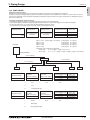
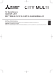
1. Electrical work.................................................................................................................................................. 4 - 4
1-1.General cautions ....................................................................................................................................... 4 - 4
1-2.Power supply for Indoor unit and Outdoor unit .......................................................................................... 4 - 5
1-3.Power cable specifications ........................................................................................................................ 4 - 7
1-4.Power supply examples............................................................................................................................. 4 - 8
2. M-NET control.................................................................................................................................................. 4 - 9
2-1.Transmission cable length limitation.......................................................................................................... 4 - 9
2-2.Transmission cable specifications ............................................................................................................. 4 - 10
2-3.System configuration restrictions............................................................................................................... 4 - 11
2-4.Address setting.......................................................................................................................................... 4 - 14
3. Piping Design................................................................................................................................................... 4 - 24
3-1.R410A Piping material............................................................................................................................... 4 - 24
3-2.Piping Design ............................................................................................................................................ 4 - 24
3-3.Refrigerant charging calculation ................................................................................................................ 4 - 26
4. Outdoor Installation.......................................................................................................................................... 4 - 28
4-1.Requirement on installation site ................................................................................................................ 4 - 28
4-2.Spacing...................................................................................................................................................... 4 - 29
4-3.Piping direction .......................................................................................................................................... 4 - 30
5. Installation information..................................................................................................................................... 4 - 31
5-1.General precautions .................................................................................................................................. 4 - 31
5-2.Precautions for Indoor unit ........................................................................................................................ 4 - 32
5-3.Precautions for Outdoor unit/Heat source unit .......................................................................................... 4 - 33
5-4.Precautions for Control-related items ........................................................................................................ 4 - 34
6. Caution for refrigerant leakage ........................................................................................................................ 4 - 35
6-1.Refrigerant property................................................................................................................................... 4 - 35
6-2.Confirm the Critical concentration and take countermeasure.................................................................... 4 - 35
SYSTEM DESIGN S SERIES
4-3
1. Electrical work
DATA U10
1-1. General cautions
S.D. S
1. Electrical work
I.
Follow ordinance of your governmental organization for technical standard related to electrical equipment, wiring
regulations, and guidance of each electric power company.
Wiring for control (hereinafter referred to as transmission cable) shall be (50mm[1-5/8in] or more) apart from power source
wiring so that it is not influenced by electric noise from power source wiring. (Do not insert transmission cable and power
source wire in the same conduit.)
Be sure to provide designated grounding work to outdoor unit.
Give some allowance to wiring for electrical part box of indoor and outdoor units, because the box is sometimes removed
at the time of service work.
Never connect 100V, 208~230V power source to terminal block of transmission cable. If connected, electrical parts will be
damaged.
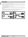
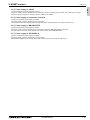
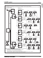
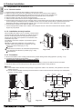
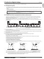
Use 2-core shield cable for transmission cable. If transmission cables of different systems are wired with the same
multiplecore cable, the resultant poor transmitting and receiving will cause erroneous operations.
When extending the transmission line, make sure to extend the shield cable as well.
Indoor unit
Outdoor
unit
OK
2-core shield cable
Indoor unit
Outdoor
unit
NO
Multiplecore cable
Remote
controller
BC controller
Remote
controller
BC controller
2-core shield cable
SYSTEM DESIGN
4-4
1. Electrical work
DATA U10
1-2. Power supply for Indoor unit and Outdoor unit
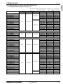
Symbols: MCA : Minimum Circuit Ampacity (=1.25xFLA) FLA : Full Load Amps
IFM :Indoor Fan Motor
Model
PLFY-P06NLMU-E
PLFY-P08NLMU-E
PLFY-P12NLMU-E
PLFY-P15NLMU-E
PLFY-P18NLMU-E
PLFY-P08NCMU-E
PLFY-P12NCMU-E
PLFY-P15NCMU-E
PLFY-P12NBMU-E
PLFY-P15NBMU-E
PLFY-P18NBMU-E
PLFY-P24NBMU-E
PLFY-P30NBMU-E
PLFY-P36NBMU-E
PMFY-P06NBMU-E
PMFY-P08NBMU-E
PMFY-P12NBMU-E
PMFY-P15NBMU-E
PEFY-P06NMAU-E3
PEFY-P08NMAU-E3
PEFY-P12NMAU-E3
PEFY-P15NMAU-E3
PEFY-P18NMAU-E3
PEFY-P24NMAU-E3
PEFY-P27NMAU-E3
PEFY-P30NMAU-E3
PEFY-P36NMAU-E3
PEFY-P48NMAU-E3
PEFY-P54NMAU-E3
PEFY-P06NMSU-E
PEFY-P08NMSU-E
PEFY-P12NMSU-E
PEFY-P15NMSU-E
PEFY-P18NMSU-E
PEFY-P24NMSU-E
PEFY-P15NMHU-E2
PEFY-P18NMHU-E2
PEFY-P24NMHU-E2
PEFY-P27NMHU-E2
PEFY-P30NMHU-E2
PEFY-P36NMHU-E2
PEFY-P48NMHU-E2
PEFY-P54NMHU-E2
PEFY-P72NMHSU-E
PEFY-P96NMHSU-E
Hz
Indoor Unit
Volts
Voltage range
Output(kW)
0.015 / 0.015
0.015 / 0.015
0.015 / 0.015
0.015 / 0.015
0.020 / 0.020
0.015 / 0.015
0.020 / 0.020
0.020 / 0.020
0.050 / 0.050
0.050 / 0.050
0.050 / 0.050
0.050 / 0.050
0.050 / 0.050
0.120 / 0.120
FLA(A)
0.34 / 0.37
0.34 / 0.37
0.34 / 0.37
0.38 / 0.42
0.39 / 0.43
0.23 / 0.23
0.28 / 0.28
0.28 / 0.28
0.51 / 0.51
0.51 / 0.51
0.51 / 0.51
0.51 / 0.51
0.51 / 0.51
1.00 / 1.00
198 to 253V
0.25 / 0.25
0.25 / 0.25
0.26 / 0.26
0.33 / 0.33
0.028 / 0.028
0.028 / 0.028
0.028 / 0.028
0.028 / 0.028
0.20 / 0.20
0.20 / 0.20
0.21 / 0.21
0.26 / 0.26
188 to 253V
1.05 / 1.05
1.05 / 1.05
1.20 / 1.20
1.45 / 1.45
1.56 / 1.56
2.73 / 2.73
2.73 / 2.73
2.73 / 2.73
3.32 / 3.32
3.41 / 3.41
3.31 / 3.31
0.085 / 0.085
0.085 / 0.085
0.085 / 0.085
0.085 / 0.085
0.085 / 0.085
0.121 / 0.121
0.121 / 0.121
0.121 / 0.121
0.244 / 0.244
0.244 / 0.244
0.244 / 0.244
0.84 / 0.84
0.84 / 0.84
0.96 / 0.96
1.16 / 1.16
1.25 / 1.25
2.18 / 2.18
2.18 / 2.18
2.18 / 2.18
2.66 / 2.66
2.73 / 2.73
2.65 / 2.65
0.47 / 0.50
0.47 / 0.50
0.68 / 0.74
1.20 / 1.33
1.20 / 1.33
1.57 / 1.73
1.63 / 1.50
1.63 / 1.50
2.11 / 1.83
2.35 / 2.13
2.70 / 2.45
4.16 / 3.67
4.16 / 3.67
4.18 / 3.69
7.7
8.2
0.023 / 0.023
0.023 / 0.023
0.032 / 0.032
0.130 / 0.130
0.130 / 0.130
0.180 / 0.180
0.17
0.17
0.25
0.26
0.31
0.49
0.49
0.55
0.87
0.87
0.32 / 0.31
0.41 / 0.39
0.46 / 0.43
0.47 / 0.45
0.64 / 0.60
0.88 / 0.83
1.30 / 1.20
1.30 / 1.20
1.69 / 1.46
1.88 / 1.70
2.16 / 1.96
3.32 / 2.94
3.32 / 2.94
3.34 / 2.95
6.2
6.6
208 / 230V
198 to 253V
60Hz
60Hz
208 / 230V
208 / 230V
188 to 253V
60Hz
IFM
MCA(A)
0.43 / 0.47
0.43 / 0.47
0.43 / 0.47
0.48 / 0.53
0.49 / 0.54
0.29 / 0.29
0.35 / 0.35
0.35 / 0.35
0.64 / 0.64
0.64 / 0.64
0.64 / 0.64
0.64 / 0.64
0.64 / 0.64
1.25 / 1.25
188 to 253V
60Hz
Output : Fan motor rated output
208 / 230V
187 to 253V
SYSTEM DESIGN
4-5
S.D. S
1-2-1. Electrical characteristics of Indoor unit
S.D. S
1. Electrical work
DATA U10
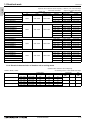
Symbols: MCA : Minimum Circuit Ampacity (=1.25xFLA) FLA : Full Load Amps
IFM :Indoor Fan Motor
Model
Indoor Unit
Volts
Voltage range
Hz
PCFY-P15NKMU-E
PCFY-P24NKMU-E
PCFY-P30NKMU-E
PCFY-P36NKMU-E
60Hz
PKFY-P06NBMU-E2
PKFY-P08NHMU-E2
PKFY-P12NHMU-E2
PKFY-P15NHMU-E2
PKFY-P18NHMU-E2
PKFY-P24NKMU-E2
PKFY-P30NKMU-E2
60Hz
PFFY-P06NEMU-E
PFFY-P08NEMU-E
PFFY-P12NEMU-E
PFFY-P15NEMU-E
PFFY-P18NEMU-E
PFFY-P24NEMU-E
60Hz
PFFY-P06NRMU-E
PFFY-P08NRMU-E
PFFY-P12NRMU-E
PFFY-P15NRMU-E
PFFY-P18NRMU-E
PFFY-P24NRMU-E
60Hz
208 / 230V
208 / 230V
208 / 230V
208 / 230V
Output : Fan motor rated output
IFM
MCA(A)
0.44 / 0.44
0.52 / 0.52
1.22 / 1.22
1.22 / 1.22
Output(kW)
0.090 / 0.090
0.095 / 0.095
0.160 / 0.160
0.160 / 0.160
FLA(A)
0.35 / 0.35
0.41 / 0.41
0.97 / 0.97
0.97 / 0.97
198 to 253V
0.19 / 0.19
0.38 / 0.38
0.38 / 0.38
0.38 / 0.38
0.38 / 0.38
0.63 / 0.63
0.63 / 0.63
0.008 / 0.008
0.030 / 0.030
0.030 / 0.030
0.030 / 0.030
0.030 / 0.030
0.056 / 0.056
0.056 / 0.056
0.15 / 0.15
0.30 / 0.30
0.30 / 0.30
0.30 / 0.30
0.30 / 0.30
0.50 / 0.50
0.50 / 0.50
188 to 253V
0.32 / 0.34
0.32 / 0.34
0.34 / 0.38
0.40 / 0.44
0.48 / 0.53
0.59 / 0.64
0.015 / 0.015
0.015 / 0.015
0.018 / 0.018
0.030 / 0.030
0.035 / 0.035
0.063 / 0.063
0.25 / 0.27
0.25 / 0.27
0.27 / 0.30
0.32 / 0.35
0.38 / 0.42
0.47 / 0.51
188 to 253V
0.32 / 0.34
0.32 / 0.34
0.34 / 0.38
0.40 / 0.44
0.48 / 0.53
0.59 / 0.64
0.015 / 0.015
0.015 / 0.015
0.018 / 0.018
0.030 / 0.030
0.035 / 0.035
0.063 / 0.063
0.25 / 0.27
0.25 / 0.27
0.27 / 0.30
0.32 / 0.35
0.38 / 0.42
0.47 / 0.51
198 to 253V
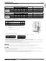
1-2-2. Electrical characteristics of Outdoor unit at cooling mode
Symbols: MCA : Minimum Circuit Ampacity
SC: Starting Current RLA: Rated Load Amps
PUMY-P-NHMU, NKMU
Outdoor Units
Model
PUMY-P36NHMU(-BS)
PUMY-P48NHMU(-BS)
PUMY-P60NKMU(-BS)
Volts/Hz
Voltage range
RLA (A)
Compressor
MCA (A)
Max. Fuse (A)
208V / 60Hz
198 to 228V
24.0
26
40
230V / 60Hz
207 to 253V
21.7
26
40
208V / 60Hz
198 to 228V
24.0
26
40
230V / 60Hz
207 to 253V
21.7
26
40
208V / 60Hz
198 to 228V
19.9
35
42
230V / 60Hz
207 to 253V
18.0
35
42
SYSTEM DESIGN
Fan
Output
(kW)
SC (A)
Output
(kW)
2.2
14
0.086 x 2
2.4
14
0.086 x 2
3.0
7
0.16 x 2
4-6
1. Electrical work
DATA U10
1-3. Power cable specifications
S.D. S
Thickness of wire for main power supply, capacities of the switch and system impedance
1-phase 2-wire, 208V, 60Hz
Minimum wire thickness (mm2/AWG)
Main cable
Branch
Ground
Swith (A)
Capacity
Fuse
Breaker for wiring
(NFB)
Breaker for current leakage
PUMY-P-NHMU
P36, P48
5.3/10
-
5.3/10
30
30
30
30A 30mA 0.1sec. or less
PUMY-P-NKMU
P60
8.4/8
-
8.4/8
40
40
40
40A 30mA 0.1sec. or less
Total operating
current of
the indoor unit
F0 = 15 or less *1
2.1/14
2.1/14
2.1/14
15
15
15
15A current sensitivity *2
F0 = 20 or less *1
3.3/12
3.3/12
3.3/12
20
20
20
20A current sensitivity *2
F0 = 30 or less *1
5.3/10
5.3/10
5.3/10
30
30
30
30A current sensitivity *2
Breaker for wiring
(NFB)
Breaker for current leakage
1-phase 2-wire, 230V, 60Hz
Minimum wire thickness (mm2/AWG)
Main cable
Branch
Ground
Swith (A)
Capacity
Fuse
PUMY-P-NHMU
P36, P48
5.3/10
-
5.3/10
30
30
30
30A 30mA 0.1sec. or less
PUMY-P-NKMU
P60
8.4/8
-
8.4/8
40
40
40
40A 30mA 0.1sec. or less
Total operating
current of
the indoor unit
F0 = 15 or less *1
2.1/14
2.1/14
2.1/14
15
15
15
15A current sensitivity *2
F0 = 20 or less *1
3.3/12
3.3/12
3.3/12
20
20
20
20A current sensitivity *2
F0 = 30 or less *1
5.3/10
5.3/10
5.3/10
30
30
30
30A current sensitivity *2
*1 Please take the larger of F1 or F2 as the value for F0.
F1 = Total operating maximum curent of the indoor units × 1.2
F2 = {V1 × (Quantity of Type1)/C} + {V1 × (Quantity of Type2)/C} + {V1 × (Quantity of Type3)/C} + {V1 × (Quantity of Others)/C}
PLFY-NBMU, PMFY-NBMU, PEFY-NMSU, PCFY-NKMU,
PKFY-NHMU, PKFY-NKMU
Type2
PEFY-NMAU
Type3
PEFY-NMHSU
Others
V1
V2
18.6
2.4
38
1.6
13.8
4.8
0
0
Other indoor unit
C : Multiple of tripping current at tripping time 0.01s
Please pick up "C" from the tripping characteristic of the breaker.
<Example of "F2" calculation>
*Condition PEFY-NMSU × 4 + PEFY-NMAU × 1, C = 8 (refer to right sample chart)
6000
600
Tripping Time [s]
Indoor unit
Type1
SAMPLE
60
10
1
F2 = 18.6 × 4/8 + 38 × 1/8
= 14.05
0.1
16 A breaker (Tripping current = 8 × 16 A at 0.01s)
0.01
1
2
3 4
6 8 10
20
C
Rated Tripping current (x)
Sample chart
*2 Current sensitivity is calculated using the following formula.
G1 = (V2 × Quantity of Type1) + (V2 × Quantity of Type2) + (V2 × Quantity of Type3) + (V2 × Quantity of Others) + (V3 × Wire length [km])
Wire thickness
V3
30 or less
G1
30 mA 0.1sec or less
Current sensitivity
1.5 mm2
48
100 or less
100 mA 0.1sec or less
2.5 mm2
56
4.0 mm2
66
1. Use a separate power supply for the outdoor unit and indoor unit.
2. Bear in mind ambient conditions (ambient temperature,direct sunlight, rain water,etc.) when proceeding with the wiring and connections.
3. The wire size is the minimum value f or metal conduit wiring. The power cord size should be 1 rank thicker consideration of voltage drops. Make sure the power-supply voltage does not
drop more than 10 %. Make sure that the voltage imbalance between the phases is 2% or less.
4. Specific wiring requirements should adhere to the wiring regulations of the region.
5. Power supply cords o f parts of appliances for outdoor use shall not be lighter than polychloroprene sheathed flexible cord (design 245 IEC57). For example, use wiring such as YZW.
6. A switch with at least 3 mm [1/8 in] contact separation in each pole shall be provided by the Air conditioner installation.
Be sure to use specified wires to connect so that no external force is imparted to terminal connections. If connections are not fixed firmly, it may cause heating or fire.
Be sure to use the appropriate type of overcurrent protection switch. Note that generated overcurrent may include some amount of direct current.
The breakers for current leakage should support Inverter circuit. (e.g. Mitsubishi Electric's NV-C series or equivalent). If no earth leakage breaker is installed, it may cause an electric shock.
Breakers for current leakage should combine using of switch.
Do not use anything other than a breaker with the correct capacity. Using a breaker of too large capacity may cause malfunction or fire.
If a large electric current flows due to malfunction or faulty wiring, earth-leakage breakers on the unit side and on the upstream side of the power supply system may both operate.
Depending on the importance of the system, separate the power supply system or take protective coordination of breakers.
SYSTEM DESIGN
4-7
1. Electrical work
DATA U10
S.D. S
1-4. Power supply examples
The local standards and/or regualtions is applicable at a higher priority.
Breaker for wiring
and current leakage
Outdoor
unit
Power supply
1-phase 2 wire.
60Hz 208/230V
Grounded
Breaker for wiring
and current leakage
Power supply
1-phase 2 wire.
60Hz 208/230V
ø1.6mm x 2
[AWG14]
pull box
1.25mm2 x 2
[AWG16]
ø1.6mm x 2
[AWG14]
Indoor unit
Group operation
Grounded
Grounded
Grounded
Grounded
Grounded
0.3~1.25mm2 x 2
[AWG22 ~ AWG16]
SYSTEM DESIGN
4-8
2. M-NET control
DATA U10
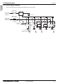
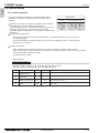
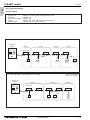
2-1. Transmission cable length limitation
2. M-NET control
L1
Group1
OC
Group3
Group5
IC
IC
IC
IC
(51)
(04)
(01)
M1M2 S
TB7
TB3
M1M2
TB5
M1M2 S
TB15
1 2
TB5
M1M2 S
(05)
TB15
1 2
TB5
M1M2 S
(06)
TB15
1 2
TB5
M1M2 S
TB15
1 2
A B
MA
L4
IC
TB7
IC
(03)
(02)
M1 M2 S
TB5
M1M2 S
TB3
M1M2
(07)
TB5 TB 15
M1M2 S 1 2
TB15
1 2
TB15
1 2
TB5
M1M2 S
a1
Power Supply Unit
PAC-SC51KUA
A B S
IC
a4
(52)
L6
MA
L3
OC
V+V-FG
A B
AG-150A-A
A B S
A B
n
L7
a3
A B
a2
Shielded
wire
a2
L2
a1
a1
a2
MA
MA
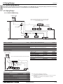
NOTE
Do not daisy-chain remote controllers.
V+V-FG
OC: Outdoor unit; IC: Indoor unit; MA: MA remote controller
2-1-2. Using ME Remote controller
ME remote controller refers to Smart ME controller.
Applicable to Outdoor as follows Long transmission cable causes voltage down, therefore, the length limitation should be obeyed to secure proper transmission.
PUMY-P-NHMU
Max. length via Outdoor (M-NET cable) L1+L2+L3+L4, L1+L2+L6+L7,L1+L2+L3+L5, L3+L4+L6+L7 <=500m[1640ft] 1.25mm2 [AWG16] or thicker
PUMY-P-NKMU
Max. length to Outdoor (M-NET cable) L1, L3+L4, L6, L2+L6, L7, L3+L5
<=200m[656ft] 1.25mm2 [AWG16] or thicker
Max. length from ME to Indoor
e1,e2,e3,e4
<=10m[32ft] *1 0.3-1.25 mm2[AWG22-16] *1
24VDC to AG-150A-A
n
<=50m[164ft] 0.75-2.0 mm2 [AWG18-14]
*1. If the length from ME to Indoor exceed 10m, use 1.25 mm2[AWG16] shielded cable, but the total length should be counted into Max. length via Outdoor.
L1
Group1
OC
Group3
IC
IC
(01)
(04)
Group5
IC
IC
(51)
TB5
M1M2 S
(05)
TB5
M1M2 S
L2
Shielded
wire
TB5
M1M2 S
e2
A B
A B
A B
(101)
(105)
(155)
ME
ME
ME
L3
OC
(06)
TB5
M1M2 S
e3
TB3
M1M2
e1
M1M2 S
TB7
L4
IC
(52)
TB7
IC
(03)
(02)
M1 M2 S
TB5
M1M2 S
TB5
M1M2 S
(07)
TB5
M1M2 S
Power Supply Unit
PAC-SC51KUA
A B S
e4
L6
L5
TB3
M1M2
IC
V+V-FG
A B
n
L7
(103)
AG-150A-A
A B S
ME
NOTE
Do not daisy-chain remote controllers.
V+V-FG
OC: Outdoor unit; IC: Indoor unit; ME: ME remote controller
SYSTEM DESIGN
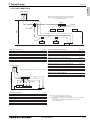
4-9
S.D. S
2-1-1. Using MA Remote controller
MA remote controller refers to Simple MA remote controller and wireless remote controller.
Applicable to Outdoor as follows Long transmission cable causes voltage down, therefore, the length limitation should be obeyed to secure proper transmission.
PUMY-P-NHMU
Max. length via Outdoor (M-NET cable) L1+L2+L3+L4, L1+L2+L6+L7, L3+L4+L6+L7 <=500m[1640ft] 1.25mm2 [AWG16] or thicker
PUMY-P-NKMU
Max. length to Outdoor (M-NET cable) L1, L3+L4, L6, L2+L6, L7
<=200m[656ft] 1.25mm2 [AWG16] or thicker
Max. length from MA to Indoor
a1+a2, a1+a2+a3+a4
<=200m[656ft] 24VDC to AG-150A-A
n
<=50m[164ft] 0.75-2.0 mm2 [AWG18-14]
2. M-NET control
DATA U10
S.D. S
2-2. Transmission cable specifications
Transmission cables (Li)
Type of cable
Cable size
Remarks
ME Remote controller cables
Shielding wire (2-core)
CVVS, CPEVS or MVVS
More than 1.25
[AWG16]
0.3 1.25
2
[AWG22 16]*2
When 10m [32ft] is exceeded, use cables with
the same specification as transmission cables.
—
MA Remote controller cables
Sheathed 2-core cable (unshielded)
CVV
mm2
*1 To wire PAC-YT53CRAU, use a wire with a diameter of 0.3
[AWG22]
*2 The use of cables 0.75 mm2 [AWG18] or greater is recommended for easy
handling.
SYSTEM DESIGN
0.3 1.25
2
[AWG22 16] *1 *2
Max length : 200m [656ft]
CVVS, MVVS: PVC insulated PVC jacketed shielded control cable
CPEVS: PE insulated PVC jacketed shielded communication cable
CVV: PV insulated PVC sheathed control cable
4 - 10
2. M-NET control
DATA U10
2-3. System configuration restrictions
S.D. S
2-3-1. Common restrictions for the CITY MULTI system
For each Outdoor unit, the maximum connectable quantity of Indoor unit is specified at its Specifications table.
A) 1 Group of Indoor units can have 1-16 Indoor units;
B) Maximum 2 remote controllers for 1 Group;
*MA/ME remote controllers cannot be present together in 1group.
*To wire PAC-YT53CRAU, use a wire with a diameter of 0.3 mm2 [AWG22]
C) 1 LOSSNAY unit can interlock maximum 16 Indoor units; 1 Indoor unit can interlock only 1 LOSSNAY unit.
D) Maximum 3 System controllers are connectable when connecting to TB3 of the Outdoor unit.
E) System controller is connectable when connecting to TB7 of the Outdoor unit, if the transmission power is supplied
by the power supply unit PAC-SC51KUA. Details refer to 2-3-3-B.
2-3-2. Ensuring proper communication power for M-NET
In order to ensure proper communication among Outdoor unit, Indoor unit, LOSSNAY and Controllers, the transmission
power situation for the M-NET should be observed. In some cases, Transmission booster should be used. Taking the
power consumption index of Indoor unit sized P06-P54 as 1, the equivalent power consumption index and supply
capability index of others are listed at Table 2-3-1 and Table 2-3-2.
Table 2-3-1 The equivalent power consumption
BC
Indoor unit
PWFY
LOSSNAY controller
CMB
Sized
PEFY-AF1200 LGH-RX-E
P36NMU-E-BU P36NMU-E-AU P72NMU-E-AU
Sized
P06-P54 P72, 96 CFMR
1
7
2
0
2
6
1
ME Remote controller/Adapter
MA RC.
PAC-YT53CRAU
PAR-FA32MA
PZ-41SLB
PZ-60DR-E
5
PZ-52SF
PAC-YG60MCA
PAC-YG66DCA
PAC-YG63MCA
0
1/4
PAR-U01MEDU
PAC-IF01AHC-J
1/2
Centralized
ON/OFF
M-NET
MN Converter
controller
Remote controller
Interface/Converter
AG-150A-A TC-24B GB-24A LMAP04U-E PAC-YT40ANRA CMS-MNF-B CMS-MNG-E MAC-333
EB-50GU-A
BAC-HD150
PAC-SF83MA-E
4
1/2
3
0
1
1/2
0
2
*RC: Remote Controller
Table 2-3-2 The equivalent power supply
Transmission Booster
Power supply unit
Expansion controller
BM ADAPTER
System Controller
Outdoor unit
PAC-SF46EPA
25
PAC-SC51KUA
5
PAC-YG50ECA
6
BAC-HD150
6
GB-50ADA-A
6
Connection TB3 andTB7 total
12
With the equivalent power consumption values in Table 2-3-1 and Table 2-3-2, PAC-SF46EPA can be designed into the airconditioner system to ensure proper system communication according to 2-3-2-A.
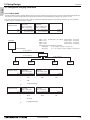
2-3-2-A) If the total power consumption reaches 12, a PAC-SF46EPA should be set.
System example
TB7
TB3
UP
TRANSMISSION BOOSTER
MODEL
PAC-SF46EPA
POWER RATING
220-240V:0.7A ~/N
50
WEIGHT
3.4kg
MADE IN JAPAN
01
Transmission
booster
(No.1)
02
ME remote
Controller
TB7
TB3
Outdoor unit
ME remote
Controller
N1
N2
Within N2, conditions 1 should be followed.
1.The total equivalent transmission power consumption
should not exceed 25.
Transmission booster (No.1) should be used,
if the total equivalent transmission power consumption reaches 12.
(Indoor units sized P72 and 96 are counted as 7);
UP
TRANSMISSION BOOSTER
MODEL
PAC-SF46EPA
POWER RATING
220-240V:0.7A ~/N
50
WEIGHT
3.4kg
MADE IN JAPAN
M-NET
24VDC
Power supply unit
PAC-SC51KUA
Transmission
booster
PAC-SF46EPA
(No.2)
LOSSNAY
unit
CENTRALIZED CONTROLLER AG-150A
Centralized controller
(AG-150A-A)
LOSSNAY
remote controller
LOSSNAY
unit
LOSSNAY
remote controller
N3
N4
Transmission booster (No.2) should be used,
if the total equivalent transmission power consumption reaches 5.
Within N4, the total equivalent transmission
power consumption should not exceed 25.
SYSTEM DESIGN
4 - 11
S.D. S
2. M-NET control
DATA U10
2-3-3. Ensuring proper power supply to System controller
The power to System controller (excluding LM-AP) is supplied via M-NET transmission line. M-NET transmission line at
TB7 side is called Central control transmission line while one at TB3 side is called Indoor-Outdoor transmission line.
There are 2 ways to supply power to the System controller .
A) Connecting to TB3 of the Outdoor unit and receiving power from the Outdoor unit.
B) Connecting to TB7 of the Outdoor unit but receiving power from power supply unit PAC-SC51KUA.
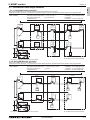
2-3-3-A. When connecting to TB3 of the Outdoor unit and receiving power from the Outdoor unit.
Maximum 3 System controllers can be connected to TB3.
If there is more than 1 Outdoor unit, it is necessary to
replace power supply switch connector CN41 with CN40
on one Outdoor unit.
Fig. 2-3-3-A
M-NET transmission lines
(Indoor-Outdoor transmission lines)
Outdoor unit
Group
System controller
(excluding LM-AP)
Group
TB3
TB7
Replacement of
CN41 with CN40
Indoor unit
M-NET transmission lines
(transmission lines
for central controller)
MA remote controller
Outdoor unit
Group
Group
TB3
TB7
Use CN41
as it is.
Indoor unit
ME remote controller
System
controller
Maximum 3 System controllers can be connected to TB3.
2-3-3-B. When connecting to TB7 of the Outdoor unit but receiving power from PAC-SC51KUA.
When using PAC-SC51KUA to supply transmission power,
the power supply connector CN41 on the Outdoor units
should be kept as it is. It is also a factory setting.
1 PAC-SC51KUA supports maximum 1 AG-150A-A or 1
EB-50GU-A unit due to the limited power 24VDC at its TB3.
However, 1 PAC-SC51KUA supplies transmission power at
its TB2 equal to 5 Indoor units, which is referable at Table
2-3-2.
If PZ-52SF, System controller, ON/OFF controller
connected to TB7 consume transmission power more than
5 (Indoor units), Transmission booster PAC-SF46EPA is
needed. PAC-SF46EPA supplies transmission power equal
to 25 Indoor units.
Fig. 2-3-3-B
M-NET transmission lines
(Indoor-Outdoor transmission lines)
Outdoor unit
Group
Group
TB3
TB7
Use CN41
as it is.
Indoor unit
M-NET transmission lines
(transmission lines
for central controller)
MA remote controller
Outdoor unit
Group
Group
TB3
TB7
Use CN41
as it is.
PAC-SC51KUA
Indoor unit
ME remote controller
System
controller
CAUTION
AG-150A-A/EB-50GU-A *1 are recommended to connect to TB7 because it performs back-up to a number of data.
In an air conditioner system has more than 1 Outdoor units, AG-150A-A/EB-50GU-A receiving transmission power through TB3 or TB7 on one of the
Outdoor units would have a risk that the connected Outdoor unit failure would stop power supply to AG-150A-A/EB-50GU-A and disrupt the whole system.
When applying apportioned electric power function, AG-150A-A/EB-50GU-A are necessary to connected to TB7 and has its own power supply unit
PAC-SC51KUA.
Note: Power supply unit PAC-SC51KUA is for AG-150A-A/EB-50GU-A.
*1: AG-150A-A is an example model of system controllers.
SYSTEM DESIGN
4 - 12
2. M-NET control
DATA U10
S.D. S
2-3-4. Power supply to LM-AP
1-phase 208-230V AC power supply is needed.
The power supply unit PAC-SC51KUA is not necessary when connecting only the LM-AP. Yet, make sure to change
the power supply changeover connector CN41 to CN40 on the LM-AP.
2-3-5. Power supply to expansion controller
1-phase 100-240VAC power supply is needed.
The power supply unit PAC-SC51KUA is not necessary.
The expansion controller supplies power through TB3, which equals 6 indoor units. (refer to Table 2-3-2)
2-3-6. Power supply to BM ADAPTER
1-phase 100-240VAC power supply is needed.
The power supply unit PAC-SC51KUA is not necessary when only BM ADAPTER is connected.
Yet, make sure to move the power jumper from CN41 to CN40 on the BM ADAPTER.
2-3-7. Power supply to GB-50ADA-A
1-phase 100-240VAC power supply is needed.
The power supply unit PAC-SC51KUA is not necessary.
GB-50ADA-A supplies power through TB3, which equals 6 indoor units. (refer to Table 2-3-2)
SYSTEM DESIGN
4 - 13
2. M-NET control
DATA U10
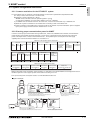
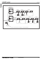
2-4-1. Switch operation
01
9
01
2 3
7 8
9
2 3
D
BC E
F 0 12
Unit address No. setting
7 8
Branch
No. setting
3456
789A
Address No. of outdoor unit, indoor unit and ME remote controller.
The address No. is set at the address setting board.
In the case of R2 system, it is necessary to set the same No. at the
branch No. switch of indoor unit as that of the BC controller
connected. (When connecting two or more branches, use the lowest
branch No.)
Caution for switch operations
Rotary switch
45 6
In order to constitute CITY MULTI in a complete system, switch
operation for setting the unit address No. and connection No. is
required.
45 6
S.D. S
2-4. Address setting
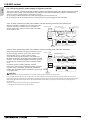
Be sure to shut off power source before switch setting. If operated with power source on, switch can
not operate properly.
No units with identical unit address shall exist in one whole air conditioner system. If set erroneously,
the system can not operate.
MA remote controller
When connecting only one remote controller to one group, it is always the main remote controller.
When connecting two remote controllers to one group, set one remote controller as the main remote controller
and the other as the sub remote controller.
The factory setting is Main .
PAC-YT53CRAU
Setting the dip switches
There are switches on the back of the top case. Remote controller Main/Sub and other function settings are performed
using these switches. Ordinarily, only change the Main/Sub setting of SW1.
(The factory settings are ON for SW1, 3, and 4 and OFF for SW2.)
SW No
3
SW contents Main
Remote controller
Main/Sub setting
Temperature display
units setting
Cooling/heating
display in AUTO mode
4
Indoor temperature
display
1
2
Comment
ON
OFF
Main
Sub
Celsius
Fahrenheit
When the temperature is displayed in [Fahrenheit], set to “OFF”.
Yes
No
When you do not want to display “Cooling” and “Heating” in the
AUTO mode, set to “OFF”.
Yes
No
When you do not want to display the indoor temperature,
set to “OFF”.
Set one of the two remote controllers at one group to “ON”.
SYSTEM DESIGN
4 - 14
2. M-NET control
DATA U10
Unit
Address setting
Example
Note
7 8
9 0 1
4 5 6
4 5 6
10
1
10
1
01
9
7 8
7 8
1
01
9
01
7 8
9
7 8
7 8
45 6
45 6
10
0
0
0
100
10
1
0
0
0
100
10
1
0
0
0
100
10
1
9 0 1
9 0 1
Please reset one of them to an address between 51
and 99 when two addresses overlap.
The address automatically becomes "100" if it is set
as "01~ 50"
Lowest address within the indoor units connected to
the BC controller (Sub) plus 50.
The smallest address of indoor unit in the group + 100
The address of main remote controller + 50
The address automatically becomes "200" if it is set
as "00"
The smallest group No. to be managed + 200
The smallest group No. to be managed is changeable.
Settings are made on the initial screen of AG-150A-A.
Settings are made with setting tool of BM ADAPTER.
2 3
2 3
4 5 6
4 5 6
2
Fixed
7 8
1
7 8
45 6
45 6
45 6
10
The smallest address of indoor unit in same refrigerant
system + 50
Assign sequential address numbers to the outdoor
units in one refrigerant circuit system. OC and OS are
automatically detected. (Note 2)
Please reset one of them to an address between 51
and 99 when two addresses overlap.
The address automatically becomes "100" if it is set
as "01~ 50"
The place of "100" is fixed to "1"
01
100
000, 201 ~ 250
201 ~ 250
7 8
7 8
45 6
000, 201 ~ 250
01
2 3
PAC-YG50ECA
9
2 3
000, 201 ~ 250
01
45 6
Fixed
01
7 8
1
2 3
1
7 8
4 5 6
4 5 6
10
2 3
151 ~ 199, 200
7 8
7 8
7 8
9 0 1
2 3
Local remote controller
4 5 6
4 5 6
9 0 1
2 3
1
2 3
System controller
4 5 6
4 5 6
1
Use the most recent address within the same group of
indoor units. Make the indoor units address connected
to the BC controller (Sub) larger than the indoor units
address connected to the BC controller (Main).
If applicable, set the sub BC controllers in an PURY
system in the following order:
(1) Indoor unit to be connected to the BC controller (Main)
(2) Indoor unit to be connected to the BC controller (No.1 Sub)
(3) Indoor unit to be connected to the BC controller (No.2 Sub)
Set the address so that (1)<(2)<(3)
The address of outdoor unit + 1
2 3
10
9
000, 201 ~ 250
LMAP04U-E
9 0 1
Fixed
AG-150A-A
GB-50ADA-A
GB-24A
EB-50GU-A
BAC-HD150
9 0 1
9
101 ~ 150
2 3
52 ~ 99, 100
9
ON/OFF remote
controller
1
2 3
ME, LOSSNAY
Remote controller
(Sub)
10
2 3
ME, LOSSNAY
Remote controller
(Main)
52 ~ 99, 100
9 0 1
2 3
BC controller
(Sub)
51 ~ 99, 100
(Note1)
2 3
BC controller
(Main)
7 8
9 0 1
Outdoor unit
2 3
01 ~ 50
2 3
7 8
9 0 1
Indoor unit
S.D. S
2-4-2. Rule of setting address
10
1
Note1: To set the address to "100", set it to "50"
Note2: Outdoor units OC and OS in one refrigerant circuit system are automatically detected.
OC and OS are ranked in descending order of capacity. If units are the same capacity, they are ranked in ascending
order of their address.
SYSTEM DESIGN
4 - 15
S.D. S
2. M-NET control
DATA U10
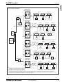
2-4-3. System example
Factory setting
Original switch setting of the outdoors, indoors, controllers, LM-AP, and BM ADAPTER at shipment is as follows.
Outdoor unit
: Address: 00, CN41: ON (Jumper), DipSW2-1: OFF
Indoor unit
: Address: 00
ME remote controller : Address: 101
LM-AP
: Address: 247, CN41: ON (Jumper), DipSW1-2: OFF
BM ADAPTER
: Address: 000, CN41: ON (Jumper)
2-4-3-1. Example : Basic (No address setting)
Outdoor unit
(PUMY)
MA R/C: PAC-YT53CRAU
Group 1
Group 2
Group 3
Group 4
00
CN40
Indoor unit
CN41
00
TB5
TB3
DipSW2-1
OFF
00
TB15
TB5
00
TB15
TB5
00
TB15
TB5
MA R/C
MA R/C
00
TB15
MA R/C
2-4-3-2. Example : Basic , Sub/main ME remote controller
Outdoor unit
(PUMY)
TB5
TB15
MA R/C
(Main)
MA R/C
(Sub)
Main R/C: PAR-U01MEDU
Sub R/C: PAR-U01MEDU
Group 1
Group 2
Group 3
51
CN40
Indoor unit
CN41
01
DipSW2-1
OFF
02
03
04
05
TB3
101
103
153
105
Main R/C
Main
R/C
Sub
R/C
Main
R/C
SYSTEM DESIGN
4 - 16
2. M-NET control
DATA U10
S.D. S
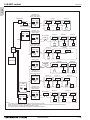
2-4-3-3. Example : AG-150A-A/GB-50ADA-A, TB7
Outdoor unit
Heat source unit
(PUHY, PQHY, PUMY)
Group 1
Group 2
Group 3
Group 4
Group 5
01
02
03
04
05
101
102
103
104
105
51
CN40
TB7
TB7
CN41
DipSW2-1*1
ON
DC30V
TB3
Power supply unit
(PAC-SC51KUA)
TB2
TB3
DC24V
000
CN40 CN41
000
AG-150A-A
GB-50ADA-A
NOTE
It is necessary to turn on the DipSW 2-1 on the outdoor unit control board when the central controller is connected.
GB-50ADA-A doesn’t need DC24V. TB3 on power supply unit doesn’t need to be connected to GB-50ADA-A.
*1 On PUHY and PURY (YKM) units, set DipSW5-1 to ON instead of DipSW2-1.
2-4-3-4. Example : Grouping in different refrigerant system
Outdoor unit
Heat source unit
(PUHY, PQHY, PUMY)
51
CN40
Group 1
01
TB7
DipSW2-1
OFF
*1
101
56
Group 4
03
04
05
105
Group 3
CN41
10
TB7
02
TB3
Outdoor unit
Heat source unit
(PUHY,PQHY,PUMY)
CN40
Group 2
CN41
DipSW2-1
OFF
*1
09
08
07
06
TB3
107
110
NOTE
It is necessary to change the connecter to CN40 on the outdoor unit control board (only one Outdoor unit / Heat source unit) when the group is set
between other refrigerant systems.
It is necessary to set on the remote controller by manual when group sets on the different refrigerant system. Please refer to remote controller
installation manual.
*1 On PUHY and PURY (YKM) units, set DipSW5-1 to ON instead of DipSW2-1.
SYSTEM DESIGN
4 - 17
S.D. S
2. M-NET control
DATA U10
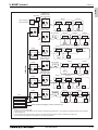
2-4-3-5. Example : 2 Outdoor units / 2 Heat source units, AG-150A-A, MA
Outdoor unit
Heat source unit
(PUHY, PQHY, PUMY)
51
CN40
TB7
Group 1
Group 2
Group 3
01
02
03
101
102
103
CN41
DipSW2-1
*1
04
TB3
ON
Outdoor unit
Heat source unit
(PURY, PQRY)
55
CN40
Group 4
56
TB7
Power supply unit
(PAC-SC51KUA)
TB2
Group 5
Group 6
CN41 BC controller
DipSW2-1
*1
TB3
05
06
TB15
07
08
TB15
09
TB15
TB15
ON
MA R/C
MA R/C
(Main)
(Sub)
MA R/C
TB3
DC24V
000
AG-150A-A
NOTE
*1 On PUHY and PURY (YKM) units, set DipSW5-1 to ON instead of DipSW2-1.
SYSTEM DESIGN
4 - 18
2. M-NET control
DATA U10
S.D. S
2-4-3-6. Example : TG-2000A
Outdoor unit
Heat source unit
(PUHY, PUMY, PQHY)
51
CN40
TB7
AG-150A-A
Group 1
DipSW2-1*3
ON
01
02
03
101
151
103
TB3
000
Outdoor unit
Heat source unit
24VDC
TB3
(PURY, PQRY)
TB2
54
CN40
LAN
Group 2
CN41
55
Power supply unit
(PAC-SC51KUA)
DipSW2-1*3
ON
Group 3
Group 4
Group 5
04
05
06
104
105
106
BC controller
CN41
TB3
Outdoor unit
Heat source unit
(PUHY, PUMY, PQHY)
Group 6
57
HUB
CN40
Group 7
CN41
07
TB7
DipSW2-1*3
ON
09
LOSSNAY
107
Outdoor unit
Heat source unit
*2
08
TB3
108
(PURY, PQRY)
TG-2000A
51
CN40
52
TB7
DipSW2-1
ON
*3
Group 1
BC controller
CN41
Group 2
01
02
03
101
151
103
TB3
Outdoor unit
Heat source unit
(PUHY, PUMY, PQHY)
54
CN40
TB7
Group 3
DipSW2-1
ON
*3
Group 5
04
05
06
104
105
106
TB3
GB-50ADA-A
Outdoor unit
Heat source unit
000
(PURY, PQRY)
57
CN40
Group 4
CN41
BC controller
CN41
58
DipSW2-1
ON
*3
Group 6
156
Group 7
07
08
09
107
108
158
TB3
NOTE
It is planned that GB-50ADA-A will be supported on TG-2000A Ver. 6.3* or later.
AG-150A-A*1 can control maximum 50 indoor units.
TG-2000A can control maximum 40 AG-150A-A*1.
TG-2000A can control maximum 2000 indoor units.
*1 Only AG-150A-A that are not connected to expansion controllers. AG-150A-A (Ver. 1 series) does not support the expansion controller (EC).
*2 TG-2000A (Ver. 5.5 or later) supports AG-150A-A (Ver. 1 series). AG-150A-A connected with PAC-YG50ECA is compatible with TG-2000A Ver. 6.1* or later.
*3 On PUHY and PURY (YKM) units, set DipSW5-1 to ON instead of DipSW2-1.
SYSTEM DESIGN
4 - 19
S.D. S
2. M-NET control
DATA U10
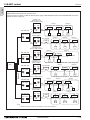
2-4-3-7. AG-150A-A + PAC-YG50ECA (Expansion Controller)
Outdoor unit
Heat source unit
(PUHY, PUMY, PQHY)
51
CN40 CN41
AG-150A-A
Group 1
8&% TB3
TB7
Power supply unit
(PAC-SC51KUA)
PAC-YG50ECA
DipSW2-1*2
ON
Group 2
01
02
03
101
151
103
TB3
Outdoor unit
Heat source unit
000
(PURY, PQRY)
CN40 CN41
54
CN40 CN41
55
LAN
DipSW2-1*2
ON
Group 3
Group 4
Group 5
04
05
06
104
105
106
BC controller
TB3
Outdoor unit
Heat source unit
(PUHY, PUMY, PQHY)
Group 6
57
CN40 CN41
HUB
Group 7
07
TB7
DipSW2-1*2
ON
08
09
TB3
LOSSNAY
107
Outdoor unit
Heat source unit
108
(PURY, PQRY)
PC Browser
51
CN40 CN41
52
TB7
DipSW2-1
ON
*2
Group 8
BC controller
Group 9
01
02
03
101
151
103
TB3
Outdoor unit
Heat source unit
(PUHY, PUMY, PQHY)
54
CN40 CN41
TB7
PAC-YG50ECA
DipSW2-1*2
ON
Group 10
Group 11
Group 12
04
05
06
104
105
106
TB3
000
CN40 CN41
156
Outdoor unit
Heat source unit
(PURY, PQRY)
PAC-YG50ECA
57
CN40 CN41
BC controller
58
000
CN40 CN41
DipSW2-1
ON
*2
Group 13
Group 14
07
08
09
107
108
158
TB3
NOTE
AG-150A-A*1 can control maximum 150 indoor units via expansion controler.
When connecting AG-150A-A to PAC-YG50ECA, TB2 for power supply unit does not need to be connected to AG-150A-A.
*1 AG-150A-A (Ver. 2.1 or later) supports the expansion controller.
*2 On PUHY and PURY (YKM) units, set DipSW5-1 to ON instead of DipSW2-1.
SYSTEM DESIGN
4 - 20
2. M-NET control
DATA U10
S.D. S
2-4-3-8. LM-AP
Outdoor unit
AG-150A-A Heat source unit
(PUHY, PQHY, PUMY)
000
51
Power supply unit
(PAC-SC51KUA)
CN40
P/S
TB7
LM-AP
DipSW2-1*1
ON
01
02
03
101
151
103
TB3
Outdoor unit
Heat source unit
(PURY, PQRY)
247
CN40 CN41
54
DipSW1-2
ON
CN40
BC controller
CN41
Group 3
Group 4
Group 5
04
05
06
104
105
106
55
TB7
DipSW2-1
ON
*1
TB3
Outdoor unit
Heat source unit
(PUHY, PQHY, PUMY)
Group 1
51
CN40
LM-AP
01
CN41 TB7
DipSW1-2
OFF
DipSW2-1
OFF
LONWORKS®
*1
CN40
DipSW1-2
OFF
DipSW2-1*1
OFF
CN40
TB7
PC
LONWORKS® card
247
CN40 CN41
DipSW2-1
OFF
CN40
Group 1
02
03
101
151
103
Group 2
*1
Group 3
CN41
01
02
03
101
102
103
TB3
Group 1
DipSW2-1
OFF
*1
153
Group 2
BC controller
52
TB7
01
CN41
Outdoor unit
Heat source unit
(PURY, PQRY)
51
LM-AP
Group 2
TB3
51
DipSW1-2
OFF
Group 1
BC controller
CN41
Outdoor unit
Heat source unit
(PUHY, PQHY, PUMY)
LM-AP
247
CN40 CN41
102
52
TB7
03
LOSSNAY
101
247
CN41
02
TB3
Outdoor unit
Heat source unit
(PURY, PQRY)
51
LM-AP
CN40
Group 2
CN41
247
CN40
Group 2
Group 1
CN41
01
02
03
101
102
152
TB3
DipSW1-2
OFF
LONWORKS® card
LONWORKS® card
Other equipments (lighting, security, elevator etc.)
NOTE
LM-AP can control 50 indoor units.
*1
It is necessary to turn on the DipSW1-2 on the LM-AP control board and the DipSW2-1 on the outdoor unit control board with central controllers
(Power supply unit).
It is necessary to change the connector to CN40 on the LM-AP control board without central controllers (Power supply unit).
*1 On PUHY and PURY (YKM) units, set DipSW5-1 to ON instead of DipSW2-1.
SYSTEM DESIGN
4 - 21
DATA U10
2-4-3-9. BM ADAPTER
BM ADAPTER can transmit max. 50 indoor units;
Change Jumper from CN41 to CN40 to activate power supply to BM ADAPTER itself for those BM ADAPTER connected
without the power supply unit.
Outdoor unit
Heat source unit
(PUHY, PUMY, PQHY)
51
CN40
Group 1
01
02
03
101
151
103
TB3
ON
Outdoor unit
Heat source unit
(PURY, PQRY)
000
CN40 CN41
54
CN40
CN41
BC controller
55
TB7
DipSW2-1*1
ON
Group 2
Group 3
04
05
06
104
105
106
Group 1
51
CN40
BM ADAPTER
Group 1
TB3
Outdoor unit
Heat source unit
(PUHY, PUMY, PQHY)
Group 2
CN41
01
000
CN40 CN41
Group 2
CN41
TB7 DipSW2-1*1
BM ADAPTER
TB7
DipSW2-1*1
ON
02
LOSSNAY
101
102
51
HUB
BM ADAPTER
CN40
52
TB7
DipSW2-1*1
ON
51
CN40
TB7
DipSW2-1*1
ON
151
103
01
02
03
101
102
103
CN41
Group 3
Group 1
DipSW2-1*1
ON
153
Group 2
BC controller
52
TB7
101
TB3
000
CN40 CN41
03
Group 2
51
CN40
02
Group 1
Outdoor unit
Heat source unit
(PURY, PQRY)
BM ADAPTER
01
CN41
000
CN40 CN41
Group 2
TB3
Outdoor unit
Heat source unit
(PUHY, PUMY, PQHY)
BM ADAPTER
Group 1
BC controller
CN41
000
CN40 CN41
03
TB3
Outdoor unit
Heat source unit
(PURY, PQRY)
BACnet ®
S.D. S
2. M-NET control
01
02
03
101
102
152
TB3
NOTE
*1 On PUHY and PURY (YKM) units, set DipSW5-1 to ON instead of DipSW2-1.
SYSTEM DESIGN
4 - 22
2. M-NET control
DATA U10
S.D. S
2-4-3-10. BM ADAPTER + PAC-YG50ECA (Expansion controller)
BM ADAPTER*1 can transmit max. 150 indoor units via expansion controllers (PAC-YG50ECA).
When the dual-set-point function is used, no expansion controllers can be connected, and only up to 50 units can be controlled
from each BAC-HD150.
Outdoor unit
BM ADAPTER
Heat source unit
® LAN1
BACnet
000
(PUHY, PUMY, PQHY)
CN40 CN41
51
CN40
Group 1
LAN2
TB7
PAC-YG50ECA*3
DipSW2-1
ON
*5
CN40 CN41
01
02
03
101
151
103
TB3
Outdoor unit
Heat source unit
(PURY, PQRY)
000
54
CN40
BC controller
CN41
55
TB7
DipSW2-1
ON
*5
TB7
CN41
DipSW2-1*5
ON
04
05
06
104
105
106
Group 7
08
CN40
LOSSNAY
107
108
52
TB7
DipSW2-1
ON
54
TB7
AG-150A-A*2
000
DipSW2-1*5
ON
CN40 CN41
TB7
PAC-YG50ECA*3
03
101
151
103
Group 4
04
05
06
Group 5
104
105
106
TB3
CN41
Group 6
DipSW2-1*5
ON
156
Group 7
BC controller
58
Power supply unit
(PAC-SC51KUA)
02
Group 3
57
CN40
01
CN41
Outdoor unit
Heat source unit
(PURY, PQRY)
PAC-YG50ECA*3
Group 2
TB3
Outdoor unit
Heat source unit
(PUHY, PUMY, PQHY)
CN40
Group 1
BC controller
CN41
*5
09
TB3
51
HUB
TB3
Group 5
07
Outdoor unit
Heat source unit
(PURY, PQRY)
24VDC
Group 4
Group 6
57
CN40
Group 3
TB3
Outdoor unit
Heat source unit
(PUHY, PUMY, PQHY)
LAN
Group 2
CN41
07
08
09
TB3
000
107
108
NOTE:
It is not necessary to connect the M-NET transmission line to the TB3 on BM ADAPTER.
Leave the power jumper of BM ADAPTER connected to CN41.
*1 BM ADAPTER (Ver. 2.00 or later) supports the expansion controller.
*2 AG-150A-A (Ver. 2.30 or later) supports the BM ADAPTER.
*3 PAC-YG50ECA (Ver. 1.30 or later) supports the BM ADAPTER.
*4 Consult your dealer for restrictions when connecting both AG-150A-A and BM ADAPTER to PAC-YG50ECA.
*5 On PUHY and PURY (YKM) units, set DipSW5-1 to ON instead of DipSW2-1.
SYSTEM DESIGN
158
4 - 23
3. Piping Design
DATA U10
3-1. R410A Piping material
The maximum operation pressure of R410A air conditioner is 4.15 MPa [601 psi]. The refrigerant piping should ensure the safety
under the maximum operation pressure. You shall follow the local industrial standard.
3-2. Piping Design
3-2-1. PUMY-P-NHMU Piping
PUMY-P-NHMU
Note1. No Joint after Header; Piping direct to Indoor Unit from Header.
Note2. The system can be designed to use only Joints, only Header,
or use both Joints and Header.
Header
A
B
Capped
H(H')
The first joint
a
b
c
IU
IU
IU
L1
C
L2
Joint
d
e
IU
IU
f
h
D
IU
Fig. 3-2-1A Piping scheme
Table3-2-1-1. Piping length
Item
Total piping length
Farthest IU from OU (L1)
Farthest IU from the first Joint (L2)
Height between OU and IU (OU above IU)
Height between OU and IU (OU under IU)
Height between IU and IU
IU : Indoor unit , OU : Outdoor unit
(m [ft.])
Piping in the figure
Max. length
A+B+C+D+a+b+c+d+e+f 120 [393']
A+C+D+f / A+B+c
80 [262']
C+D+f / B+c
30 [98']
H
50 [164']
H'
20 [65']
h
12 [39']
Table3-2-1-2. Piping "A"size selection rule
Outdoor and the first-Joint/Header
Pipe(Liquid)
PUMY-P-NHMU=CMY-Y62-G-E
ø9.52 [3/8"]
PUMY-P-NHMU=CMY-Y64,Y68-G-Eb ø9.52 [3/8"]
(mm [in.])
Pipe(Gas)
ø15.88 [5/8"]
ø15.88 [5/8"]
Table3-2-1-3. Piping "B","C","D"size selection rule
Total down-stream Indoor capacity
Pipe(Liquid)
~ P62
ø9.52 [3/8"]
(mm [in.])
Pipe(Gas)
ø15.88 [5/8"]
Table3-2-1-4. Piping "a","b","c","d","e","f"size selection rule
Indoor Unit size
Pipe(Liquid)
P06,P08,P12,P15,P18
ø6.35 [1/4"]
P24,P27,P30,P36,P48,P54
ø9.52 [3/8"]
(mm [in.])
Pipe(Gas)
ø12.70 [1/2"]
ø15.88 [5/8"]
Table3-2-1-5. Joint, Header selection rule
Joint
4-branch Header
CMY-Y62-G-E
CMY-Y64-G-E
8-branch Header
CMY-Y68-G-E
OU: Outdoor Unit, IU: Indoor Unit
PUMY-P-NHMU
Note1. No Joint after Header; Piping direct to Indoor Unit from Header;
A
L1
* For details of installation of Joint, header, and distributor, refer to its Installation Manual.
L2
Header
H (H')
Capped
a
b
IU
IU
c
d
e
f
IU
IU
IU
h
S.D. S
3. Piping Design
IU
Fig. 3-2-1B Piping scheme
Table3-2-1B1. Piping length
Item
Total piping length
Farthest IU from OU (L1)
Farthest IU from Header (L2)
Height between OU and IU (OU above IU)
Height between OU and IU (OU under IU)
Height between IU and IU
Piping in the figure
A+a+b+c+d+e+f
A+f
f
H
H'
h
(m [ft.])
Max. length
120 [393']
80 [262']
30 [98']
50 [164']
20 [65']
12 [39']
Note3. Indoor capacity is described as its model size.
For example, PEFY-P08NMAU-E3, capacity P08;
Note4. Total down-stream Indoor capacity is the summary of the model size of Indoors
downstream.
For example, PEFY-P08NMAU-E3+PEFY-P06NMAU-E3: Total Indoor
capacity=P08+P06=P14;
SYSTEM DESIGN
4 - 24
3. Piping Design
DATA U10
S.D. S
3-2-2. PUMY-P-NKMU Piping
PUMY-P-NKMU
Note1. No Joint after Header; Piping direct to Indoor Unit from Header.
Note2. The system can be designed to use only Joints, only Header,
or use both Joints and Header.
Header
A
B
Capped
H(H')
The first joint
a
b
c
IU
IU
IU
L1
C
L2
Joint
e
IU
IU
f
h
D
d
IU
Fig. 3-2-2A Piping scheme
Table3-2-2-1. Piping length
Item
Total piping length
Farthest IU from OU (L1)
Farthest IU from the first Joint (L2)
Height between OU and IU (OU above IU)
Height between OU and IU (OU under IU)
Height between IU and IU
IU : Indoor unit , OU : Outdoor unit
(m [ft.])
Piping in the figure
Max. length
A+B+C+D+a+b+c+d+e+f 150 [492']
A+C+D+f / A+B+c
80 [262']
C+D+f / B+c
30 [98']
H
50 [164']
H'
40 [131']
h
15 [49']
Table3-2-2-2. Piping "A"size selection rule
Outdoor and the first-Joint/Header
Pipe(Liquid)
PUMY-P-NKMU=CMY-Y62-G-E
ø9.52 [3/8"]
PUMY-P-NKMU=CMY-Y64,Y68-G-Eb ø9.52 [3/8"]
(mm [in.])
Pipe(Gas)
ø19.05 [3/4"]
ø19.05 [3/4"]
Table3-2-2-3. Piping "B","C","D"size selection rule
Total down-stream Indoor capacity
Pipe(Liquid)
~ P78
ø9.52 [3/8"]
(mm [in.])
Pipe(Gas)
ø19.05 [3/4"]
Table3-2-2-4. Piping "a","b","c","d","e","f"size selection rule
Indoor Unit size
Pipe(Liquid)
P06,P08,P12,P15,P18
ø6.35 [1/4"]
P24,P27,P30,P36,P48,P54
ø9.52 [3/8"]
P72
ø9.52 [3/8"]
(mm [in.])
Pipe(Gas)
ø12.70 [1/2"]
ø15.88 [5/8"]
ø19.05 [3/4"]
Table3-2-2-5. Joint, Header selection rule
Joint
4-branch Header
CMY-Y62-G-E
CMY-Y64-G-E
8-branch Header
CMY-Y68-G-E
OU: Outdoor Unit, IU: Indoor Unit
PUMY-P-NKMU
Note1. No Joint after Header; Piping direct to Indoor Unit from Header;
A
L1
* For details of installation of Joint, header, and distributor, refer to its Installation Manual.
L2
H (H')
Header
Capped
b
IU
IU
c
d
e
f
IU
IU
IU
h
a
IU
Fig. 3-2-2B Piping scheme
Table3-2-2B1. Piping length
Item
Total piping length
Farthest IU from OU (L1)
Farthest IU from Header (L2)
Height between OU and IU (OU above IU)
Height between OU and IU (OU under IU)
Height between IU and IU
Piping in the figure
A+a+b+c+d+e+f
A+f
f
H
H'
h
(m [ft.])
Max. length
150 [492']
80 [262']
30 [98']
50 [164']
40 [131']
15 [49']
Note3. Indoor capacity is described as its model size.
For example, PEFY-P08NMAU-E3, capacity P08;
Note4. Total down-stream Indoor capacity is the summary of the model size of Indoors
downstream.
For example, PEFY-P08NMAU-E3+PEFY-P06NMAU-E3: Total Indoor
capacity=P08+P06=P14;
SYSTEM DESIGN
4 - 25
3. Piping Design
DATA U10
S.D. S
3-3. Refrigerant charging calculation
3-3-1. PUMY-P-NHMU
Original refrigerant charge for PUMY-P-NHMU is 8.5 kg [18.75 lbs], including 3 kg [106 oz] for 50 m [164 ft.] total extended piping length use.
Thus, there is no need to charge additional refrigerant to the system if the total extended piping length is 50 m [164 ft.] or less.
If the total extended piping length is over 50 m [164 ft.], calculate the additional refrigerant using following procedure. Yet, if the calculated
result is negative, no additional charge is needed.
Additional
refrigerant charge
=
(kg)
[oz]
Total length of liquid
pipe sized
ø9.52 x 0.06 (kg/m)
ø3/8" x 0.65 [oz/ft.]
+
Total length of liquid
pipe sized
ø6.35 x 0.024 (kg/m)
ø1/4" x 0.26 [oz/ft.]
(m) x 0.06 (kg/m)
(ft.) x 0.65 [oz/ft.]
Original charge
-
(m) x 0.024 (kg/m)
(ft.) x 0.26 [oz/ft.]
Indoor 1:
Indoor 2:
Indoor 3:
Indoor 4:
Example:
P24
P15
P08
P06
3.0 (kg)
106 [oz]
A=ø9.52 [3/8"] 30 m [98 ft.]
a=ø9.52 [3/8"]
b=ø6.35 [1/4"]
c=ø6.35 [1/4"]
d=ø6.35 [1/4"]
15 m [49 ft.]
10 m [32 ft.]
10 m [32 ft.]
20 m [65 ft.]
Total length of each liquid pipe is as follows
ø9.52 [3/8"]
A + a = 30 [98] + 15 [49] = 45 m [147 ft.]
ø6.35 [1/4"]
b + c + d = 10 [32] + 10 [32] + 20 [65] = 40 m [129 ft.]
PUMY-P48NHMU
A ( 30 m [98 ft.] )
a ( 15 m [49 ft.] )
b ( 20 m [65 ft.] )
b ( 10 m [32 ft.] )
P24
c ( 10 m [32 ft.] )
P15
Total length of liquid
pipe sized
=
ø9.52 x 0.06 (kg/m)
Additional
refrigerant charge
(kg)
P08
Total length of liquid
pipe sized
+
ø6.35 x 0.024 (kg/m)
45 (m) x 0.06 (kg/m)
=
2.70
=
0.66
P06
Original charge
-
40 (m) x 0.024 (kg/m)
0.96
+
3.0(kg)
-
3.00
0.7 kg (round-up)
Total length of liquid
pipe sized
=
ø3/8" x 0.65 [oz/ft.]
Additional
refrigerant charge
(oz)
Total length of liquid
pipe sized
+
ø1/4" x 0.26 [oz/ft.]
147 (ft.) x 0.65 [oz/ft.]
=
95.55
=
23.09 [oz]
Original charge
-
129 (ft.) x 0.26 [oz/ft.]
33.54
+
106 [oz]
-
106
1.5 [lbs] (round-up)
SYSTEM DESIGN
4 - 26
3. Piping Design
DATA U10
Additional refrigerant charge
Refrigerant for the extended piping is not included in the outdoor unit when the unit is shipped from the factory.
Therefore, charge each refrigerant piping system with additional refrigerant at the installation site. In addition, in order to carry out service,
enter the size and length of each liquid pipe and additional refrigerant charge amounts in the spaces provided on the “Refrigerant amount”
plate on the outdoor unit.
Calculation of additional refrigerant charge
• Calculate the additional charge using the liquid pipe size and length of the extended piping.
• Calculate the additional refrigerant charge using the procedure shown to the right, and charge with the additional refrigerant.
• For amounts less than 0.1 kg, round up the calculated additional refrigerant charge.
(For example, if the calculated charge is 32.92 kg, round up the charge to 33.0 kg.)
Additional
refrigerant charge
=
Pipe size
Liquid pipe ø6.35
+
Pipe size
Liquid pipe ø9.52
(m) × 0.027 (kg/m)
0.29 (oz/ft)
(kg)
[oz]
Total capacity of
connected indoor units
Amount for the
indoor units
– 42
2.0 kg (71 oz)
(m) × 0.07 (kg/m)
0.75 (oz/ft)
Indoor 1:
Indoor 2:
Indoor 3:
Indoor 4:
Indoor 5:
Example:
+
P24
P15
P08
P06
P06
43 – 60
2.5 kg (88 oz)
61 – 78
3.0 kg (106 oz)
A=ø9.52 [3/8"] 30 m [98 ft.]
a=ø9.52 [3/8"]
b=ø6.35 [1/4"]
c=ø6.35 [1/4"]
d=ø6.35 [1/4"]
e=ø6.35 [1/4"]
15 m [49 ft.]
10 m [32 ft.]
10 m [32 ft.]
20 m [65 ft.]
15 m [49 ft.]
Total length of each liquid pipe is as follows
ø9.52 [3/8"]
A + a = 30 [98] + 15 [49] = 45 m [147 ft.]
ø6.35 [1/4"]
b + c + d + e = 10 [32] + 10 [32] + 20 [65] + 15 [49] = 55 m [180 ft.]
PUMY-P60NKMU
A ( 30 m [98 ft.] )
e ( 15 m [49 ft.] )
a ( 15 m [49 ft.] )
d ( 20 m [65 ft.] )
b ( 10 m [32 ft.] )
P24
c ( 10 m [32 ft.] )
P15
Total length of liquid
pipe sized
=
ø9.52 x 0.07 (kg/m)
Additional
refrigerant charge
(kg)
Total length of liquid
pipe sized
+
ø6.35 x 0.027 (kg/m)
45 (m) x 0.07 (kg/m)
=
3.15
=
7.14
P06
P08
+
55 (m) x 0.027 (kg/m)
1.49
+
+
Total capacity of
connected indoor units
Amount for the
indoor units
– 42
43 – 60
61 – 78
2.0 kg (71 oz)
2.5 kg (88 oz)
3.0 kg (106 oz)
P06
2.5
7.2 kg (round-up)
Total length of liquid
pipe sized
=
ø3/8" x 0.75 [oz/ft.]
Additional
refrigerant charge
(oz)
Total length of liquid
pipe sized
+
ø1/4" x 0.29 [oz/ft.]
147 (ft.) x 0.75 [oz/ft.]
=
110.25
=
250.45 [oz]
+
180 (ft.) x 0.29 [oz/ft.]
52.2
+
+
Total capacity of
connected indoor units
Amount for the
indoor units
– 42
43 – 60
61 – 78
2.0 kg (71 oz)
2.5 kg (88 oz)
3.0 kg (106 oz)
88
251 [oz] (round-up)
SYSTEM DESIGN
4 - 27
S.D. S
3-3-2. PUMY-P-NKMU
4. Outdoor Installation
DATA U10
4-1. Requirement on installation site
4-1-1. General caution
A. Avoid locations exposed to direct sunlight or other sources of heat.
B. Select a location from which noise emitted by the unit will not inconvenience the neighbors.
C. Select a location permitting easy wiring and pipe access to the power source and indoor unit.
D. Avoid locations where combustible gases may leak, be produced, flow, or accumulate.
E. Note that water may drain from the unit during operation.
F. Select a level location that can bear the weight and vibration of the unit.
G. Avoid locations where the unit can be covered by snow. In areas where heavy snow fall is anticipated, special precautions
such as raising the installation location or installing a hood on the air intake must be taken to prevent the snow from
blocking the air intake or blowing directly against it. This can reduce the airflow and a malfunction may result.
H. Avoid locations exposed to oil, steam, or sulfuric gas.
I . Use the transportation handles of the outdoor unit to transport the unit. If the unit is carried from the bottom, hands or
fingers may be pinched.
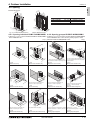
4-1-2. Installation at windy location.
When installing the outdoor unit on a rooftop or other location
unprotected from the wind, situate the air outlet of the unit so
that it is not directly exposed to strong winds.Strong wind
entering the air outlet may impede the normal airflow and a
malfunction may result.
The following shows two examples of precautions against
strong winds.
Install an optional air guide if the unit is installed in a
location where strong winds from a typhoon, etc. may
directly enter the air outlet. (Fig. 4-1-2a)
Air guide
Position the unit so that the air outlet blows perpendicularly
to the seasonal wind direction, if possible. (Fig. 4-1-2b)
Wind direction
Fig. 4-1-2a
Fig. 4-1-2b
4-1-3. Foundation
A. Be sure to install the unit in a sturdy, level surface to prevent rattling noises during operation. (see Fig. 4-1-3)
B. Foundation specifications are as follows.
mm [in.]
Thickness of concrete
120 [4-3/4"]
Weight-bearing capacity
320 kg [706lbs]
Foundation bolt Bolt length
M10 [3/8"] 70 [2-25/32"]
C. Make sure that the length of the foundation bolt is within 30 mm [1-3/16"] of the bottom surface of the base.
D. Secure the base of the unit firmly with four-M10 [3/8"] foundation bolts in sturdy locations.
Warning:
A. The foundation base should be strong enough to support the outdoor unit, otherwise, it may fall down and cause
damage or injures.
B. The unit must be installed according to the instructions in order to minimize the risk of damage from earthquakes,
typhoons, or strong winds.
600
[23-5/8"]
(mm [in.])
175
[6-29/32"]
25
[1"]
Min. 10
[13/32"] 175
[6-29/32"]
370
[14-9/16"]
Min. 360
[14-3/16"]
330
[13"]
600
[23-5/8"]
950
[37-13/32"]
PUMY-P-NHMU
600
[23-5/8"]
M10 (3/8") bolt
Base
As long as possible.
Vent
Min. 10
[13/32"]
Fig. 4-1-3
SYSTEM DESIGN
225
[8-7/8"]
225
[8-7/8"]
1050
[41-11/32"]
25
[1"]
330
[13"]
Min. 460
[18-1/8"]
370
[14-9/16"]
600
[23-5/8"]
Max.30[1-3/16"]
S.D. S
4. Outdoor Installation
PUMY-P-NKMU
4 - 28
4. Outdoor Installation
DATA U10
4-2. Spacing
30 "]
0+
3 3 -3/16
+1
[13
]
1350
[53-5/32"]
[6
-2
9/ 175
32
"] [ 60
23 0
-5
/8"
[41 1050
-11
/32
"]
Connectable Indoor capacity
PUMY-P36NHMU
P18 - P46
PUMY-P48NHMU
P24 - P62
PUMY-P60NKMU
P30 - P78
1338
[52-11/16" ]
3 0 16"]
/
0+
3 0 6"+1-3
1
/
[37 950
13
[ 11 -13
/32
"
S.D. S
External dimension.
[8- 225
7/8
"]
3
0
37 -19/
[14
]
6
[23 00
-5/
8" ]
2"]
Connectable Indoor unit
P06-P36, 1-6 units
P06-P54, 1-8 units
P06-P72, 1-12 units
0
37 6" ]
1
-9/
[14
Fig. 4-2-1 PUMY-P-NHMU dimension
PUMY-P-NKMU dimension
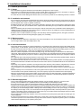
4-2-1. Spacing individual PUMY-P-NHMU/NKMU 4-2-2. Spacing grouped PUMY-P-NHMU/NKMU
Follow Fig. 4-2-2~7 to space individual PUMY-P-NHMU/NKMU Follow Fig. 4-2-8~13 to space grouped PUMY-P-NHMU/NKMU
at the installation site. Leave 10 mm [13/32"] space or more
at the installation site.
mm[in.] between PUMY-P-NHMU/NKMU units.
mm[in.]
6"]
1
11/
1000
[39-3/8"]
x.
Ma
6"]
00
x. 3 -13/1
[11
1500[59-1/16"]
19-
[
500
Ma
]
0
30 /16"
-13
[11
[59 1500
-1/
16
"]
0 ]
15 /32"
9
2
[5-
Fig. 4-2-2
Obstacles at rear only
0 "]
30 /16
3
1
[11
0[
150
59-
1/1
]
6"
0
50 -11/1
[19
6"]
* In case of side-by-side installation, <=3 units;
* When using an optional air outlet guide,
* Do not install the optional air outlet guides
the clearance is 1000 mm [39-3/8"] or more. for upward airflow.
Fig. 4-2-8
Obstacles at rear or front only
Fig. 4-2-3
Obstacles at rear and above only
Fig. 4-2-9
Obstacles at rear and above only
150 ]
32"
29/
[5-
20
[7- 0
7/8
"]
0
30 "]
6
1
/
-13
2
[7- 00
7/8
"]
[11
Fig. 4-2-4
Obstacles at rear and sides only
8"]
-3/
9
0[3
00
15 /16"]
-1
[59
0
10
0
]
50 /16"
-11
[19
0
60 /8"]
-5
00 "]
10 -3/8
[39
00
20 /4"]
-3
[78
[23
* Using an optional air outlet guide, the
clearance >= 500 mm [19-11/16"].
* Using an optional air outlet guide, the
clearance >= 1000 mm [39-3/8"].
* Using an optional air outlet guide, the
clearance >= 1000 mm [39-3/8"].
Fig. 4-2-5
Obstacles at front only
Fig. 4-2-10
Obstacles at front and rear only
Fig. 4-2-11
Parallel individuals arrangement
6"]
/1
-11
[19
00
0
15 "] [ 250
9-27
/32"
/32
]
-29
00 ] [5
10 3/8"
9
3
[
1500
[59-1/16"]
150[5-29/32"]
x. 5
Ma
0
50 "]
/16
2
[9-2 50
7/32
"]
500
[19-11/16"]
"]
00
15 -1/16
[59
0
60 /8"]
-5
[23
9-11
00
30 1/8"] [1
8[11
1
[59 500
-1/
16
"]
0
80 "]
2
1/
1-
[3
* Using an optional air outlet guide, the
clearance >= 500 mm [19-11/16"].
* NO upward airflow outlet guide.
* Using an optional air outlet guide for upward * Stacked layer <= 2 units;
airflow, the clearance >= 1500 mm [59-1/16"]. * Side-by-side stacked groups <= 2 groups;
Fig. 4-2-6
Obstacles at front and rear only
Fig. 4-2-7
Obstacles at rear, sides and above only
Fig. 4-2-12
Parallel groups arrangement
SYSTEM DESIGN
Fig. 4-2-13
Stacked groups arrangement
4 - 29
4. Outdoor Installation
DATA U10
S.D. S
4-3. Piping direction
4-3-1. PUMY-P-NHMU
Rear piping
Front piping cover
Piping cover
Stop valve
Service panel
Bend radius : 100 mm [3-15/16"] - 150 mm [5-29/32"]
Front piping
Right piping
Bottom piping
4-3-2. PUMY-P-NKMU
Front piping cover
Piping cover
Stop valve
Service panel
Bend radius : 100 mm [3-15/16"] - 150 mm [5-29/32"]
SYSTEM DESIGN
4 - 30
5. Installation information
DATA U10
5-1. General precautions
5. Installation information
The air-conditioning system described in this Data Book is designed for human comfort.
This product is not designed for preservation of food, animals, plants, precision equipment, or art objects. To prevent
quality loss, do not use the product for purposes other than what it is designed for.
To reduce the risk of water leakage and electric shock, do not use the product for air-conditioning vehicles or vessels.
5-1-2. Installation environment
Do not install any unit other than the dedicated unit in a place where the voltage changes a lot, large amounts of mineral
oil (e.g., cutting oil) are present, cooking oil may splash, or a large quantity of steam can be generated such as a kitchen.
Do not install the unit in acidic or alkaline environment.
Installation should not be performed in the locations exposed to chlorine or other corrosive gases. Avoid near a sewer.
To reduce the risk of fire, do not install the unit in a place where flammable gas may be leaked or inflammable material
is present.
This air conditioning unit has a built-in microcomputer. Take the noise effects into consideration when deciding the installation position. Especially in a place where antenna or electronic device are installed, it is recommended that the air
conditioning unit be installed away from them.
Install the unit on a solid foundation according to the local safety measures against typhoons, wind gusts, and earthquakes to prevent the unit from being damaged, toppling over, and falling.
5-1-3. Backup system
In a place where air conditioner's malfunctions may exert crucial influence, it is recommended to have two or more systems of single outdoor units with multiple indoor units.
5-1-4. Unit characteristics
Heat pump efficiency depends on outdoor temperature. In the heating mode, performance drops as the outside air temperature drops. In cold climates, performance can be poor. Warm air would continue to be trapped near the ceiling and
the floor level would continue to stay cold. In this case, heat pumps require a supplemental heating system or air circulator. Before purchasing them, consult your local distributor for selecting the unit and system.
When the outdoor temperature is low and the humidity is high, the heat exchanger on the outdoor unit side tends to
collect frost, which reduces its heating performance. To remove the frost, Auto-defrost function will be activated and the
heating mode will temporarily stop for 3-10 minutes. Heating mode will automatically resume upon completion of defrost
process.
Air conditioner with a heat pump requires time to warm up the whole room after the heating operation begins, because
the system circulates warm air in order to warm up the whole room.
The sound levels were obtained in an anechoic room. The sound levels during actual operation are usually higher than
the simulated values due to ambient noise and echoes. Refer to the section on "SOUND LEVELS" for the measurement
location.
Depending on the operation conditions, the unit generates noise caused by valve actuation, refrigerant flow, and pressure changes even when operating normally. Please consider to avoid location where quietness is required.
For BC controller, it is recommended to unit to be installed in places such as ceilings of corridor, restrooms and plant
rooms.
The total capacity of the connected indoor units can be greater than the capacity of the outdoor unit. However, when the
connected indoor units operate simultaneously, each unit's capacity may become smaller than the rated capacity.
When the unit is started up for the first time within 12 hours after power on or after power failure, it performs initial startup
operation (capacity control operation) to prevent damage to the compressor. The initial startup operation requires 90
minutes maximum to complete, depending on the operation load.
5-1-5. Relevant equipment
Use an earth leakage breaker (ELB) with medium sensitivity, and an activation speed of 0.1 second or less.
Consult your local distributor or a qualified technician when installing an earth leakage breaker.
If the unit is inverter type, select an earth leakage breaker for handling high harmonic waves and surges.
Leakage current is generated not only through the air conditioning unit but also through the power wires. Therefore, the
leakage current of the main power supply is greater than the total leakage current of each unit. Take into consideration
the capacity of the earth leakage breaker or leakage alarm when installing one at the main power supply. To measure
the leakage current simply on site, use a measurement tool equipped with a filter, and clamp all the four power wires
together. The leakage current measured on the ground wire may not accurate because the leakage current from other
systems may be included to the measurement value.
Do not install a phase advancing capacitor on the unit connected to the same power system with an inverter type unit
and its equipment.
If a large current flows due to the product malfunctions or faulty wiring, both the earth leakage breaker on the product
side and the upstream overcurrent breaker may trip almost at the same time. Separate the power system or coordinate
all the breakers depending on the system's priority level.
SYSTEM DESIGN
4 - 31
S.D. S
5-1-1. Usage
S.D. S
5. Installation information
DATA U10
5-1-6. Unit installation
Your local distributor or a qualified technician must read the Installation Manual that is provided with each unit carefully
before performing installation work.
Consult your local distributor or a qualified technician when installing the unit. Improper installation by an unqualified
person may result in water leakage, electric shock, or fire.
Ensure there is enough space around each unit.
5-1-7. Optional accessories
Only use accessories recommended by Mitsubishi Electric. Consult your local distributor or a qualified technician when
installing them. Improper installation by an unqualified person may result in water leakage, electric leakage, system
breakdown, or fire.
Some optional accessories may not be compatible with the air conditioning unit to be used or may not suitable for the
installation conditions. Check the compatibility when considering any accessories.
Note that some optional accessories may affect the air conditioner's external form, appearance, weight, operating
sound, and other characteristics.
5-1-8. Operation/Maintenance
Read the Instruction Book that is provided with each unit carefully prior to use.
Maintenance or cleaning of each unit may be risky and require expertise. Read the Instruction Book to ensure safety.
Consult your local distributor or a qualified technician when special expertise is required such as when the indoor unit
needs to be cleaned.
5-2. Precautions for Indoor unit
5-2-1. Operating environment
The refrigerant (R410A) used for air conditioner is non-toxic and nonflammable. However, if the refrigerant leaks, the
oxygen level may drop to harmful levels. If the air conditioner is installed in a small room, measures must be taken to
prevent the refrigerant concentration from exceeding the safety limit even if the refrigerant should leak.
If the units operate in the cooling mode at the humidity above 80%, condensation may collect and drip from the indoor
units.
5-2-2. Unit characteristics
The return air temperature display on the remote controller may differ from the ones on the other thermometers.
The clock on the remote controller may be displayed with a time lag of approximately one minute every month.
The temperature using a built-in temperature sensor on the remote controller may differ from the actual room temperature due to the effect of the wall temperature.
Use a built-in thermostat on the remote controller or a separately-sold thermostat when indoor units installed on or in
the ceiling operate the automatic cooling/heating switchover.
The room temperature may rise drastically due to Thermo OFF in the places where the air conditioning load is large
such as computer rooms.
Be sure to use a regular filter. If an irregular filter is installed, the unit may not operate properly, and the operation noise
may increase.
The room temperature may rise over the preset temperature in the environment where the heating air conditioning load
is small.
5-2-3. Unit installation
For simultaneous cooling/heating operation type air conditioners (R2, H2i R2, WR2 series), the G-type BC controller
cannot be connected to the P144 outdoor unit model or above, and the G- and GA-type BC controllers cannot be connected to the P264 model or above. The GB- and HB-type BC controllers (sub) cannot be connected to the outdoor unit
directly, and be sure to use them with GA- and HA-type BC controllers (main).
The insulation for low pressure pipe between the BC controller and outdoor unit shall be at least 20 mm thick. If the unit
is installed on the top floor or in a high-temperature, high-humidity environment, thicker insulation may be necessary.
Do not have any branching points on the downstream of the refrigerant pipe header.
When a field-supplied external thermistor is installed or when a device for the demand control is used, abnormal stop of
the unit or damage of the electromagnetic contactor may occur. Consult your local distributor for details.
When indoor units operate a fresh air intake, install a filter in the duct (field-supplied) to remove the dust from the air.
The 4-way or 2-way Airflow Ceiling Cassette Type units that have an outside air inlet can be connected to the duct, but
need a booster fan to be installed at site. Refer to the chapter "Indoor Unit" for the available range for fresh air intake
volume.
Operating fresh air intake on the indoor unit may increase the sound pressure level.
SYSTEM DESIGN
4 - 32
5. Installation information
DATA U10
5-3. Precautions for Outdoor unit/Heat source unit
Outdoor unit with salt-resistant specification is recommended to use in a place where it is subject to salt air.
Even when the unit with salt-resistant specification is used, it is not completely protected against corrosion. Be sure to
follow the directions or precautions described in Instructions Book and Installation Manual for installation and maintenance. The salt-resistant specification is referred to the guidelines published by JRAIA (JRA9002).
Install the unit in a place where the flow of discharge air is not obstructed. If not, the short-cycling of discharge air may
occur.
Provide proper drainage around the unit base, because the condensation may collect and drip from the outdoor units.
Provide water-proof protection to the floor when installing the units on the rooftop.
In a region where snowfall is expected, install the unit so that the outlet faces away from the direction of the wind, and
install a snow guard to protect the unit from snow. Install the unit on a base approximately 50 cm higher than the expected snowfall. Close the openings for pipes and wiring, because the ingress of water and small animals may cause equipment damage. If SUS snow guard is used, refer to the Installation Manual that comes with the snow guard and take
caution for the installation to avoid the risk of corrosion.
When the unit is expected to operate continuously for a long period of time at outside air temperatures of below 0ºC,
take appropriate measures, such as the use of a unit base heater, to prevent icing on the unit base. (Not applicable to
the PUMY-P-NHMU series)
Install the snow guard so that the outlet/inlet faces away from the direction of the wind.
When the snow accumulates approximately 50 cm or more on the snow guard, remove the snow from the guard. Install
a roof that is strong enough to withstand snow loads in a place where snow accumulates.
Provide proper protection around the outdoor units in places such as schools to avoid the risk of injury.
A cooling tower and heat source water circuit should be a closed circuit that water is not exposed to the atmosphere.
When a tank is installed to ensure that the circuit has enough water, minimize the contact with outside air so that the
oxygen from being dissolved in the water should be 1 mg/L or less.
Install a strainer (50 mesh or more recommended) on the water pipe inlet on the heat source unit.
Interlock the heat source unit and water circuit pump.
Note the followings to prevent the freeze bursting of pipe when the heat source unit is installed in a place where the
ambient temperature can be 0ºC or below.
Keep the water circulating to prevent it from freezing when the ambient temperature is 0ºC or below.
Before a long period of non use, be sure to purge the water out of the unit.
5-3-2. Circulating water
Follow the guidelines published by JRAIA (JRA-GL02-1994) to check the water quality of the water in the heat source
unit regularly.
A cooling tower and heat source water circuit should be a closed circuit that water is not exposed to the atmosphere.
When a tank is installed to ensure that the circuit has enough water, minimize the contact with outside air so that the
oxygen from being dissolved in the water should be 1 mg/L or less.
5-3-3. Unit characteristics
When the Thermo ON and OFF is frequently repeated on the indoor unit, the operation status of outdoor units may become unstable.
5-3-4. Relevant equipment
Provide grounding in accordance with the local regulations.
SYSTEM DESIGN
4 - 33
S.D. S
5-3-1. Installation environment
5. Installation information
DATA U10
S.D. S
5-4. Precautions for Control-related items
5-4-1. Product specification
To introduce the MELANS system, a consultation with us is required in advance. Especially to introduce the electricity
charge apportioning function or energy-save function, further detailed consultation is required. Consult your local distributor for details.
Billing calculation for AG-150A-A, GB-50ADA-A, EB-50GU-A, TG-2000A, or the billing calculation unit is unique and
based on our original method. (Backup operation is included.) It is not based on the metering method, and do not use it
for official business purposes. It is not the method that the amount of electric power consumption (input) by air conditioner is calculated. Note that the electric power consumption by air conditioner is apportioned by using the ratio corresponding to the operation status (output) for each air conditioner (indoor unit) in this method.
In the apportioned billing function for AG-150A-A, GB-50ADA-A, and EB-50GU-A, use separate watthour meters for
A-control units, K-control units*1., and packaged air conditioner for City Multi air conditioners. It is recommended to use
an individual watthour meter for the large-capacity indoor unit (with two or more addresses).
When using the peak cut function on the AG-150A-A, GB-50ADA-A or EB-50GU-A, note that the control is performed
once every minute and it takes time to obtain the effect of the control. Take appropriate measures such as lowering the
criterion value. Power consumption may exceed the limits if AG-150A-A, GB-50ADA-A or EB-50GU-A malfunctions or
stops. Provide a back-up remedy as necessary.
The controllers cannot operate while the indoor unit is OFF. (No error)
Turn ON the power to the indoor unit when operating the controllers.
When using the interlocked control function on the AG-150A-A, GB-50ADA-A, EB-50GU-A, PAC-YG66DCA, or PACYG63MCA, do not use it for the control for the fire prevention or security. (This function should never be used in the way
that would put people's lives at risk.) Provide any methods or circuit that allow ON/OFF operation using an external
switch in case of failure.
5-4-2. Installation environment
The surge protection for the transmission line may be required in areas where lightning strikes frequently occur.
A receiver for a wireless remote controller may not work properly due to the effect of general lighting. Leave a space of
at least 1 m between the general lighting and receiver.
When the Auto-elevating panel is used and the operation is made by using a wired remote controller, install the wired
remote controller to the place where all air conditioners controlled (at least the bottom part of them) can be seen from
the wired remote controller. If not, the descending panel may cause damage or injury, and be sure to use a wireless
remote controller designed for use with elevating panel (sold separately).
Install the wired remote controller (switch box) to the place where the following conditions are met.
Where installation surface is flat
Where the remote controller can detect an accurate room temperature
The temperature sensors that detect a room temperature are installed both on the remote controller and indoor unit.
When a room temperature is detected using the sensor on the remote controller, the main remote controller is used to
detect a room temperature. In this case, follow the instructions below.
Install the controller in a place where it is not subject to the heat source.
(If the remote controller faces direct sunlight or supply air flow direction, the remote controller cannot detect an accurate
room temperature.)
Install the controller in a place where an average room temperature can be detected.
Install the controller in a place where no other wires are present around the temperature sensor.
(If other wires are present, the remote controller cannot detect an accurate room temperature.)
To prevent unauthorized access, always use a security device such as a VPN router when connecting
AG-150A-A, GB-50ADA-A, EB-50GU-A or TG-2000A to the Internet.
*1.EB-50GU-A cannot be used to control K-control units.
SYSTEM DESIGN
4 - 34
6. Caution for refrigerant leakage
DATA U10
The installer and/or air conditioning system specialist shall secure safety against refrigerant leakage according to local regulations or standards.
The following standard may be applicable if no local regulation or standard is available.
6. Caution for refrigerant leakage
R410A refrigerant is harmless and incombustible. The R410A is heavier than the indoor air in density. Leakage of the refrigerant in a room
has possibility to lead to a hypoxia situation. Therefore, the Critial concentration specified below shall not be exceeded even if the leakage
happens.
Critical concentration
Critical concentration hereby is the refrigerant concentration in which no human body would be hurt if immediate measures can be taken
when refrigerant leakage happens.
Critical concentration of R410A: 0.44kg/m3
(The weight of refrigeration gas per 1 m3 air conditioning space.);
The Critical concentration is subject to ISO5149, EN378-1.
For the CITY MULTI system, the concentration of refrigerant leaked should not have a chance to exceed the Critical concentration in
any situntion.
6-2. Confirm the Critical concentration and take countermeasure
The maximum refrigerant leakage concentration (Rmax) is defined as the result of the possible maximum refrigerant weight (Wmax)
leaked into a room divided by its room capacity (V). It is referable to Fig.6-1. The refrigerant of Outdoor unit here includes its original
charge and additional charge at the site.
The additional charge is calculated according to “3-3. Refrigerant charging calculation” and shall not be over charged at the site.
Procedure 6-2-1~3 tells how to confirm maximum refrigerant leakage concentration (Rmax) and how to take countermeasures against
a possible leakage.
Outdoor unit (No.1)
Outdoor unit (No.1)
Outdoor unit (No.2)
Flow of refrigerant
Indoor unit
Flow of refrigerant
Flow of refrigerant
Indoor unit
Indoor unit
Maximum refrigerant leakage concentration (Rmax)
Rmax=Wmax / V (kg/m3)
Maximum refrigerant leakage concentration (Rmax)
Rmax=Wmax / V (kg/m3) W1: Refrigerant weight of Outdoor unit No.1
where, Wmax=W1+W2 W2: Refrigerant weight of Outdoor unit No.2
Fig. 6-1 The maximum refrigerant leakage concentration
6-2-1.Find the room capacity (V),
If a room having total opening area more than 0.15% of the floor area at a low position with another room/space, the two rooms/space are
considered as one. The total space shall be added up.
6-2-2.Find the possible maximum leakage (Wmax) in the room. If a room has Indoor unit(s) from more than 1 Outdoor unit, add up the refrigerant of the Outdoor units.
6-2-3.Divide (Wmax) by (V) to get the maximum refrigerant leakage concentration (Rmax).
6-2-4.Find if there is any room in which the maximum refrigerant leakage concentration (Rmax) is over 0.44kg/m3.
If no, then the CITY MULTI is safe against refrigerant leakage.
If yes, following countermeasure is recommended to do at site.
Countermeasure 1: Let-out (making V bigger)
Design an opening of more than 0.15% of the floor area at a low position of the wall to let out the refrigerant whenever leaked.
e.g.make the upper and lower seams of door big enough.
Countermeasure 2: Smaller total charge (making Wmax smaller)
e.g.Avoid connecting more than 1 Outdoor unit to one room.
e.g.Using smaller model size but more Outdoor units.
e.g.Shorten the refrigerant piping as much as possible.
Countermeasure 3: Fresh air in from the ceiling (Ventilation)
As the density of the refrigerant is bigger than that of the air.Fresh air supply from the ceiling is better than air exhausting from the ceiling.
Fresh air supply solution refers to Fig.6-2~4.
Fresh air supply fan (always ON)
Refrigerant pipe
Refrigerant pipe (high pressure pipe)
Fresh air supply fan
Refrigerant pipe
to Outdoor unit
Indoor space
(Floor)
Opening
Opening
Sensor for refrigerant leakage (Oxygen sensor or refrigerant sensor).
[At 0.3m height from the floor]
Fig.6-2. Fresh air supply always ON
to Outdoor unit
Indoor unit
Indoor space
(Floor)
Refrigerant stop valve
to Outdoor unit
Indoor unit
Indoor space
Fresh air supply fan
Fig.6-3. Fresh air supply upon sensor action
Indoor unit
(Floor)
Opening
Sensor for refrigerant leakage (Oxygen sensor or refrigerant sensor).
[At 0.3m height from the floor]
Fig.6-4. Fresh air supply and refrigerant
shut-off upon sensor action
Note 1.Countermeasure 3 should be done in a proper way in which the fresh air supply shall be on whenever the leakage happens.
Note 2.In principle, MITSUBISHI ELECTRIC requires proper piping design, installation and air-tight testing after installation to avoid leakage happening.
In the area should earthquake happen, anti-vibration measures should be fully considered.
The piping should consider the extension due to the temperature variation.
SYSTEM DESIGN
4 - 35
S.D. S
6-1. Refrigerant property