1
EXACOMtm
MODEL VCR-2020
DIGITAL VOICE CALL RECORDER
TECHNICAL Guide
7000134B
EXACOM, Inc.
99 Airport Road
Concord, New Hampshire
(603) 228-0706
EXACOM
VCR-2020
2
COPYRIGHT
Copyright 1991, 92, 93, 94, 95, 96 all rights reserved by EXACOM, Inc.
No part of this publication, software, or product may be recreated,
reproduced, transmitted, transcribed, or translated into any other computer
or other languages, in any way without the express written consent of
EXACOM, Inc.
DISCLAIMER
EXACOM, Inc. makes no representations or warranties with respect to
this publication, software, or product and specifically disclaims any implied
warranties of merchantability or fitness for any particular purpose.
EXACOM, Inc. further reserves the right to revise this publication, software,
or product and make changes without any obligation to notify any person of
such revisions.
LIMITATION OF LIABILITY
EXACOM, Inc. will not be liable for any damages, including any lost
profits, lost savings or other incidental or consequential damages arising out
of the use or inability to use this product, even if EXACOM, Inc. or its
authorized dealer has been advised of the possibility of such damages, or for
any claim by any other party.
EXACOM, Inc. will have its liability limited to the repair or
replacement of the supplied original program diskette, associated publication
and any part or parts of the product or system for the period of the warranty.
WARRANTY
EXACOM, Inc. will warrant this product against defects in material
and workmanship under a limited warranty for a period of one year from the
date of shipment. During this one year period the liability and obligation of
EXACOM, Inc. will be expressly limited to the replacement or repair of any
part or parts of this product or system. This warranty does not apply to the
product if it is operated under conditions other than those for which the
system was designed. Also, this warranty does not apply if the product has
been altered in any way which would be detrimental to the performance or
life of the product, or by misapplication, misuse, negligence, or accident.
After the expiration of the warranty period, EXACOM, Inc. will
provide the same repair and replacement service at the then-current rate for
materials and services.
Copyright 1991, 92, 93, 94, 95, 96 all rights reserved by EXACOM, Inc.
EXACOM
VCR-2020
3
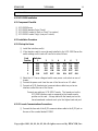
ISSUE CONTROL (VCR - 2020)
ISSUE
A
B
DATE
11-01994
5-23-1996
CHANGE
Original Draft
Update
Copyright 1991, 92, 93, 94, 95, 96 all rights reserved by EXACOM, Inc.
EXACOM
VCR-2020
4
SECTION
PAGE
1.00 - INTRODUCTION
1.10
PURPOSE .................................................................... 6
1.20
REGULATORY INFORMATION ...................................... 6
1.21
Telco Notification......................................................... 6
1.22
Incidence of Harm ........................................................ 6
1.23
Changes in Service ....................................................... 7
1.24
Maintenance Limitations................................................. 7
2.00 - GENERAL DESCRIPTION
2.10
SYSTEM FEATURES ..................................................... 8
2.11
ADVANCED FEATURES................................................ 9
2.20
TECHNOLOGY AND SYSTEM DESCRIPTION ................... 9
2.30
SYSTEM COMPONENTS...............................................13
2.31
VCR-2020 Server ........................................................13
2.32
Line Interface Card(s)...................................................13
2.33
Console Unit(s)...........................................................13
2.34
External Equipment .....................................................14
3.00 - SYSTEM SPECIFICATIONS
3.10
Performance.................................................................15
3.11
Controls......................................................................15
3.12
Indicators ....................................................................15
3.13
Digital Storage..............................................................15
3.14
Environmental ..............................................................15
3.15
Electrical.....................................................................16
3.16
Physical ......................................................................16
Copyright 1991, 92, 93, 94, 95, 96 all rights reserved by EXACOM, Inc.
EXACOM
VCR-2020
5
4.00 - INSTALLATION
4.10
SITE PLANNING .........................................................17
4.20
UNPACKING VCR-2020 System Components ......................17
4.30
VCR-2020 INSTALLATION ............................................18
4.31
Component Checklist....................................................18
4.32
Installation Procedure ...................................................18
4.32.1
Set up the Server.......................................................18
4.32.2
Console Communication Connections .............................18
4.32.3
Powering the VCR-2020 Console ..................................19
4.32.4
Speaker Configuration ................................................19
4.32.5
Record Activation Methods..........................................19
Voltage Level Start .................................................20
External Source Start ...............................................21
Loop Current Start ..................................................22
Bridging Across Headset...........................................23
Radio / Contact Closure. PTT ....................................24
VOR / VOX ..........................................................24
4.33
Generating Record Warning Tones : Beep Tone ...................27
4.34
Adjusting Gain ...........................................................27
4.35
AGC (Automatic Gain Control) .......................................27
4.36
VCR-2020 Grounding...................................................28
5.00 - INITIALIZATION
5.10
INSTALLATION CHECKLIST ........................................28
5.20
POWER UP SEQUENCE ................................................28
APPENDIX A - Reference Tables
A.1 SW1 Switch Group...........................................................29
A.2 SW2 Switch Group...........................................................29
A.3 EXTERNAL POWER.......................................................29
APPENDIX B - Serial Input for the VCR-2020
B.1
ANI Time Synch..............................................................30
B.2
ANI Formats ..................................................................30
Copyright 1991, 92, 93, 94, 95, 96 all rights reserved by EXACOM, Inc.
EXACOM
VCR-2020
6
1.00 INTRODUCTION
1.10 PURPOSE
This manual provides the information necessary to install and operate the EXACOM
Model VCR-2020 Digital Voice Call Recorder. It is designed to be a comprehensive
guide for installation and maintenance personnel covering installation procedures,
maintenance steps and other technical matters. In addition, it provides detailed
information on the features and operation of the VCR-2020.
1.20 REGULATORY INFORMATION (FCC)
The Federal Communications Commission (FCC) has established rules which allow the
direct connection of the VCR-2020 to the telephone network. Compliance with these
rules is essential to maintaining the integrity of the telephone network.
1.21 Telco Notification
Before connecting the VCR-2020 to the telephone network, the local serving telephone
company may be given advance notice of intention to use customer provided equipment
(CPE) and provided with the following information:
1. Trunk numbers to be connected to the system.
2. The FCC Registration Number located on the VCR-2020.
(1IJUSA-61233-RC-N)
3. The Ringer Equivalence Number located on the VCR-2020.
(0.0)
4. The USOC jack required for direct interconnection with the telephone
network.
(USOC RJ11)
1.22 Incidence of Harm
If the telephone company determines the customer provided equipment (CPE) id faulty
and possibly causing harm or interruption to the telephone network. It should be
disconnected until repair can be effected. If this is not done the telephone company
may temporarily disconnect service.
Copyright 1991, 92, 93, 94, 95, 96 all rights reserved by EXACOM, Inc.
EXACOM
VCR-2020
7
1.23 Changes in Service
The local serving telephone company may make changes in its communications
facilities or procedures. If these changes should affect the use of the VCR-2020 or
compatibility with the network, the serving telephone company must give written notice
to the user to allow uninterrupted service.
1.24 Maintenance Limitations
Maintenance on the VCR-2020 is to be performed by, or under the direct supervision of
the manufacturer or its authorized agent. The user may not make any changes and/or
repairs except as specifically noted in this manual. If unauthorized alterations or
repairs are performed, any remaining warranty may be voided.
Copyright 1991, 92, 93, 94, 95, 96 all rights reserved by EXACOM, Inc.
EXACOM
VCR-2020
8
2.00 GENERAL DESCRIPTION
The VCR-2020 Digital Voice Call Recorder System is designed to assist emergency
service personnel by offering instant playback of recorded calls. Communications are
recorded with a time stamp and may be played back instantly to verify important
information.
The system is compatible with E-911 systems and will record and display ANI
(Automatic Number Identification) for all incoming calls, provided that the ANI is
made available to the VCR-2020 in DTMF format.
The VCR-2020 is unique in that it will support up to 20 consoles which are networked
together allowing the supervisor to monitor any position on the system without
disrupting recording.
2.10 SYSTEM FEATURES
•
•
•
•
•
•
•
•
•
•
•
•
•
•
•
•
•
•
•
•
Record via 1 to 20 consoles per system
Up to 1000 minutes of storage dynamically allocated
Ability to save multiple messages from being erased
ANI (Automatic Number Identification - DTMF) if provided
Real time clock with time-of-day for message orientation
Visual display indicators (operator screen)
Time of day clock
ANI Display
Day/date
Function Control Indication
Selectable beep tone generator for recording notification
Headset Jack
Cassette tape output jack
Wide dynamic range AGC (automatic gain control)
Internal 5 watt amplifier, speaker and volume control
Compatible with ACD's (automatic call distributor : single line or key telephone
systems and radio systems
Serial data input for ANI and/or Time Sync
Telephone interfacing
• Voltage or current activated
• Voice activation (VOR / VOX)
• External contact closure activation
Anti-static protection
FCC Part 15.68 and NRTL Safety Approved (UL)
Copyright 1991, 92, 93, 94, 95, 96 all rights reserved by EXACOM, Inc.
EXACOM
VCR-2020
9
2.11 ADVANCED FEATURES
•
•
•
Network capabilities up to 20 consoles/stations
Fast forward/reverse, pause, slow speed playback
Supervisor mode capabilities
• Position select
• Monitor live or previous recording of other positions
2.20 TECHNOLOGY AND SYSTEM DESCRIPTION
The EXACOM Model VCR-2020 Digital Voice Call Recorder uses proprietary stateof-the-art telecommunication digital signaling processing and semiconductor technology
to provide a bridging interface to a single telephone line for voice recording and
playback.
Copyright 1991, 92, 93, 94, 95, 96 all rights reserved by EXACOM, Inc.
EXACOM
VCR-2020
10
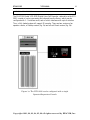
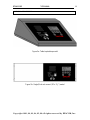
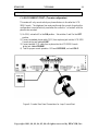
The EXACOM Model VCR-2020 Digital Voice Call Recorder, referred to as the VCR2020, consists of a micro processing unit referred to as the Server, which may be
configured with 1 - 5 interface cards, each of which interfaces with up to 4 consoles.
Thus, a fully loaded system will support 20 consoles. There are two versions of an
operator console, a Desktop version (fig. 2a) and a Rack Mount version (fig. 2b).
Figure 1a: The VCR-2020 can be configured with a single
Operator/Supervisor Console
Copyright 1991, 92, 93, 94, 95, 96 all rights reserved by EXACOM, Inc.
EXACOM
VCR-2020
11
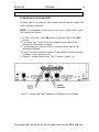
Figure 1b: Up to a total of twenty Operator/Supervisor Consoles
Copyright 1991, 92, 93, 94, 95, 96 all rights reserved by EXACOM, Inc.
EXACOM
VCR-2020
12
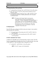
Figure 2a: Table top desktop model
Figure 2b: Single/Dual rack mount (19"x 5¼") model
Copyright 1991, 92, 93, 94, 95, 96 all rights reserved by EXACOM, Inc.
EXACOM
VCR-2020
13
2.30 SYSTEM COMPONENTS
There are three basic components which make up the VCR-2020:
1. VCR-2020 Server
2. (1 to 5) Interface Cards
3. (1 to 20) Consoles (rack mount or desktop)
2.31 VCR-2020 Server
The Server is an EXACOM Micro Computer System, Disk Controller card, Monitor
card, Hard Drive, Floppy Drive, and Power Supply. The Server can be configured for
400 up to 1000 minutes of voice storage.
2.32 Interface Card(s)
The VCR-2020 Interface Card(s) is mounted in the Server and provide a digital
communication interface between consoles and the server voice storage unit. Each
interface card supports up to 4 consoles. Up to 5 interface cards may be mounted in a
server. Interface card installation is performed at the manufacturer and fully configured
and tested before shipped. The interface card contains the VCR-2020 program in
permanent on-board memory. The VCR-2020 program is self starting on power up and
requires no user intervention.
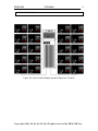
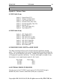
2.33 Console(s) (Rack mount or Desk top)
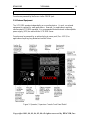
The VCR-2020 Consoles are self contained units providing the basic user interface to
the system through a six-button keypad and four-line backlit Liquid Crystal Display
(LCD). Figure 3 shows the layout and describes the functionality of the interface.
The four-line LCD provides visual feedback to the operator. The display provides the
operator with time and date of stored messages, as well as other system message related
information. In addition, during the first 15 seconds of a call, if DTMF digits are
received, they will be stored with the call and displayed during playback. The Console
also has a speaker with volume control, headset, and cassette tape output jack for
playback monitoring and recording.
Copyright 1991, 92, 93, 94, 95, 96 all rights reserved by EXACOM, Inc.
EXACOM
VCR-2020
14
Consoles are powered by the Server via the COMM jack.
2.34 External Equipment
The VCR-2020 operates independently as a recording device. As such, no external
equipment is required for most applications. However, for applications requiring
uninterrupted VCR-2020 operation, it is recommended that an external uninterruptable
power supply (UPS) be used with the VCR-2020 Server.
Consoles may be powered by an optional plug-in power pack (Sec. 4.32.3) for
applications requiring long distances from the Server.
Figure 3: Operator / Supervisor Console Front Panel Detail
Copyright 1991, 92, 93, 94, 95, 96 all rights reserved by EXACOM, Inc.
EXACOM
VCR-2020
15
3.00
SYSTEM SPECIFICATIONS
3.10
Performance
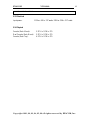
Digital Codec:
Digitization Rate:
Frequency Response:
Signal to Noise Ration:
Distortion:
Audio Input:
Input Impedance:
Audio Output:
ADPCM
64Kbps
300 to 3000Hz
43 db. C message weighted
4% THD (1khz 0 db input)
-30 dbm to +10 dbm
>5 Meg bridging
5 watts into speaker
3.11 Controls
Keyboard Type:
Message Control:
FREV/FFWD:
Normal/Slow:
Memory Control:
Clock Control:
System Control:
Monitor Audio:
Supervisor Key:
6 button membrane
Play/Pause, Stop
Message Select, Fast Forward/Reverse
Message Play Speed
Save/Clear
Display/Set Hrs. Min. Sec
Display call counter, Reset call counter, Ready/Play
Playback volume
Key switch to enable Supervisor mode
3.12 Indicators
System Display:
Audio Indicators:
4-line 20 char. alpha/numeric backlit LCD
Speaker, headset jack
3.13 Digital Storage
Memory Type:
Memory Size:
Recording Time:
Hard Disk
100MB to 225MB
400 to 1000 minutes
3.14 Environmental
Ambient Temperature:
0 to 50 degrees Celsius
Humidity:
0 to 95% non-condensing
Storage Temperature: -18 to 50 degrees Celsius
Copyright 1991, 92, 93, 94, 95, 96 all rights reserved by EXACOM, Inc.
EXACOM
VCR-2020
16
3.15 Electrical
Input power:
115Vac. 60Hz. 217 watts: 220Vac. 50Hz. 217 watts
3.16 Physical
Console (Rack Mount):
Dual Console (Rack Mount)
Console (Desk Top):
5.25"H x 19"W x 9"D
5.25"H x 19"W x 9"D
4.25"H x 10"W x 8"D
Copyright 1991, 92, 93, 94, 95, 96 all rights reserved by EXACOM, Inc.
EXACOM
VCR-2020
17
4.00 INSTALLATION
4.10 Site Planning
The VCR-2020, like most electronic equipment, should not be subject to harsh
environmental conditions. To assure ease of servicing and reliable operation, several
factors must be considered when planning the system installation. Always consider the
following BEFORE installing the VCR-2020.
A) The VCR-2020 Server may be mounted in several different configurations,
table/desktop, or on a shelf in the general area it will be servicing. Each
installation should use the configuration best suited to permit ease of
serviceability and integration with associated systems.
B) The VCR-2020 Consoles may be 19" rack mounted in the dispatch console or
located on the desk top for supervisor functions. In either case the Console
should be located as close to the server as possible to provide optimum
performance.
C) The VCR-2020 Server power supply operates on 110 or 220 Vac As such,
an appropriate receptacle compliant with local electrical codes must be provided
within 4ft. of the VCR-2020.
D) The VCR-2020 should be located in a well ventilated area having a
temperature range of 0 to 50 degrees C, and a humidity range of 5 to 95% (noncondensing).
E) Accessibility of the VCR-2020 for servicing and lighting.
F) Protection from flooding, flammable materials, excessive dust and vibration.
4.20 UNPACKING THE VCR-2020 SYSTEM COMPONENTS
Remove the VCR-2020 from the shipping carton and place it on a level working area.
Remove the plastic wrapping and inspect the VCR-2020 for physical damage. If there
is any sign of damage contact authorized service personnel immediately for assistance.
The VCR-2020 should be serviced by authorized service personnel ONLY. Do not
remove the VCR-2020 power supply cover or warranty may be voided.
Copyright 1991, 92, 93, 94, 95, 96 all rights reserved by EXACOM, Inc.
EXACOM
VCR-2020
18
4.30 VCR-2020 Installation
4.31 Component Checklist
❏
❏
❏
❏
VCR-2020 Server
VCR-2020 Interface Ports (Cards)
VCR-2020 Console(s) (Rack or Desk Top version)
VCR-2020 Console Key(s) (one per Console)
4.32 Installation Procedure
4.32.1 Set up the Server
❏ Install the interface card(s)
❑ If the interface card(s) are not already installed in the VCR-2020 Server the
switch settings on the card will have to be set as follows:
Card
Position
1
2
3
4
5
Switches
1
OFF
OFF
OFF
OFF
ON
2
OFF
OFF
ON
ON
OFF
3
OFF
ON
OFF
ON
OFF
4
OFF
ON
ON
ON
ON
5
ON
OFF
ON
OFF
ON
6
OFF
ON
ON
OFF
OFF
7
OFF
OFF
OFF
ON
ON
❏ Select the AC Power voltage at switch near power cord socket on rear of
chassis.
❏ Connect the power cord from the rear of the Server to an AC outlet.
❑ Connect an RJ22 (handset size) communications cable to a port on an
interface card at the rear of the Server:
Connect one cable per VCR-2020 Console. The lowest port on the
VCR-2020 interface card corresponds to the lowest console
position on the card. Always start with the lowest port on the
lowest numbered card and work up to the highest card and port.
4.32.2 Console Communications Connections
❏ Connect the free end of the RJ22 communications cable to the RJ22 jack on
the rear of the console labeled COMM.
Copyright 1991, 92, 93, 94, 95, 96 all rights reserved by EXACOM, Inc.
EXACOM
VCR-2020
19
4.32.3 Powering the VCR-2020 Console
❏ If communications cable length exceeds maximum allowable length for wire
gauge used (please refer to Appendix A) an external power supply will need
to be connected to the jack on the rear of the console labeled EXT. PWR.
(please refer to Appendix A for EXT PWR specifications).
4.32.2 Speaker Configuration
❏ If the VCR-1776 speaker or headset jacks are to be implemented positions 8
and 9 on the terminal block must be connected to each other. The unit is
shipped from the factory with this installed. If the headset jacks are used the
console speaker will be automatically disabled.
❏ If an external speaker is to be used, remove the jumper between position 8 &
9, and connect the speaker to positions 9 and 10 on the terminal block.
4.32.3 Record Inputs
Two separate inputs are available, each providing a high impedance differential
input suitable for connection directly to telephone lines. These are combined
internally to the single recording channel. When the second input (positions 3
& 4 on the terminal block, or the second line on the RJ11 jack) is not used, a 1K
Ohm resistor should be connected between terminal block positions 3 & 4 to
minimize possible noise pickup.
4.32.4 Record Activation Methods
❏ Choose one of the following methods to detect and record phone calls and/or
radio transmissions.
A) Voltage Level Start
B) External Source Start
C) Loop Current Start
D) Bridging Across Headset
E) Radio (through relay closure)
F) VOR / VOX
Note: The following sections describe each method in detail. Not every method
will be appropriate in every case.
Copyright 1991, 92, 93, 94, 95, 96 all rights reserved by EXACOM, Inc.
EXACOM
VCR-2020
20
A) Voltage Level Start: Parallel (Bridging) Connection
{Two wire configuration}
This method is best used if more than one phone is connected to the telephone
line. This will record activity from any phone on that line, and cannot disrupt
telephone service to any phone.
NOTE: The VCR-2020 Console does not need to be near any of the phones
being recorded if the system is configured this way.
1) On SW1, set switch 2 to the ON position. Set switches 1 and 3 to the OFF
position.
2) Connect a standard phone cable (RJ11) from a phone jack into the VCR-2020
Console at the jack labeled LINE (primary pair).
3) Test for proper record operation. Off hook-RECORD. on hook-IDLE.
NOTE: The off hook detector for the primary pair is polarity sensitive. With the
phone line connected, position 1 on the terminal block must be more positive
than position 2 on the terminal block. If it is not, then tip and ring must be
swapped prior to the RJ11 jack labeled LINE.
Figure 4: Console Rear Panel Connections for Voltage Level Start
Copyright 1991, 92, 93, 94, 95, 96 all rights reserved by EXACOM, Inc.
EXACOM
VCR-2020
21
B) EXTERNAL SOURCE START:
Used when a signal separate from the phone line is used to activate recording
(normally an isolated switch or relay contact, but will also detect changes in
voltage).
1) On SW1, set switch 1 to the ON position. Set switches 2 and 3 to the OFF
position.
2) Connect the start signal wires to position 5 and 6 on the terminal block.
3) Connect audio signal to inner pair of jack labeled LINE (or to position 1 and
2 on the terminal block).
4) Finally, the VCR-2020 Console will need to be adjusted to detect changes in
the voltage level. To adjust:
a) Boot the system.
b) Take one of the phones on the line off-hook.
c) Adjust the Potentiometer in the rear of the VCR-2020 Console labeled
LEV until the VCR-2020 Console LCD reads RECORD.
d) Place the phone back on-hook and readjust the LEV Potentiometer until
the VCR-2020 Console LCD reads IDLE.
e) Repeat step b) through d) as necessary until the VCR-2020 responds with
RECORD when off-hook and IDLE when on-hook every time.
NOTE: The wires connected to positions 5 and 6 on the terminal block may
need to be swapped if step e) appears to be working backwards.
Figure 5: Console Rear Panel Connections for External Source Start
Copyright 1991, 92, 93, 94, 95, 96 all rights reserved by EXACOM, Inc.
EXACOM
VCR-2020
22
C) LOOP CURRENT START: (Two wire configuration)
This mode will only record activity on phones that are in line after the VCR2020 Console. The telephone line must pass through the console, therefore this
configuration is most effectively used when the console is "co-located" with the
phone to be recorded.
1) On SW1, set switch 3 to the ON position. Set switches 1 and 2 to the OFF
position.
2) Connect a standard phone cable (RJ11) from a phone jack into the VCR-2020
Console at the jack labeled LINE.
3) Connect another RJ11 cable from a phone into the VCR-2020 Console
at the jack labeled PHONE.
4) Test for proper record operation. Off-hook RECORD, on-hook IDLE.
Figure 6: Console Rear Panel Connections for Loop Current Start
Copyright 1991, 92, 93, 94, 95, 96 all rights reserved by EXACOM, Inc.
EXACOM
VCR-2020
23
D) BRIDGING ACROSS HEADSET:
Primarily used on key systems or other systems where an operator headset is the
most convenient access point.
NOTE: This arrangement uses the external source start to detect the DC power
to the headset microphone.
1) On SW1, set Switch 1 to the ON position. Set Switch 2 and 3 to the OFF
position.
2) The primary pair (1 and 2) of the four conductor phone cable will be
connected to receiver pair of headset.
3) The secondary pair (3 and 4) of the four conductor phone cable will be
connected to transmit.
4) Position 5 must be connected to position 3 and position 6 must be connected
to position 4 on the terminal block.
5) Adjust for voltage detection (as in Part B. Section 4, steps b - e).
Figure 7: Console Rear Panel Connections for Bridging Across Headset
Copyright 1991, 92, 93, 94, 95, 96 all rights reserved by EXACOM, Inc.
EXACOM
VCR-2020
24
E) RADIO (Contact Closures, PTT)
Uses external start to detect signal from radio equipment.
1) On SW1, set Switch 1 to the ON position. Set Switch 2 and 3 to the OFF
position.
2) Audio sources can be connected either to primary or secondary pair or both.
If transmit and receive are separate.
3) Positions 5 and 6 on the terminal block connect to either a dry contact (T,R
relay) or PTT (voltage sense).
4) Adjust for voltage detection (as Part B, Section 4, steps b - e).
5) Test for proper record operation. Key closure RECORD, Key open IDLE.
Note: Remove 1K resistor if input 2 is used.
Figure 8: Console Rear Panel Connections for Radio Interface
F) VOR/VOX: (When no external start signal is available.)
1) Connect the audio source to the primary or secondary pair on the jack
labeled LINE (or position 1 and 2 or 3 and 4 respectively on the terminal
block).
2) Adjust potentiometer labeled VOR to recognize and reject ambient noise.
This will establish the ON/OFF levels for VOR/VOX connection.
3) Set Switches 1,2 and 3 on SW1 in the OFF position.
Copyright 1991, 92, 93, 94, 95, 96 all rights reserved by EXACOM, Inc.
EXACOM
VCR-2020
25
4) VOR/VOX requires some additional switch manipulation to insure correct
execution of desired ATTACK and HOLD times.
a) ATTACK time is the amount of time required for verification of valid
audio signals. ATTACK time is adjusted through two switches which
present four different ATTACK time settings. (SW2, Switch 3 and 4.)
ATTACK ON TIMES
0.000 sec.
0.124 sec.
0.250 sec.
0.475 sec.
Switch 3
OFF
ON
OFF
ON
Switch 4
OFF
OFF *
ON
ON
* NOTE: Use this setting for adjusting VOX level.
b) HOLD time is adjusted using three switches which present
eight different HOLD time settings. (SW2 Switches 5, 6 and 7.)
HOLD (OFF) TIMES
VOX Deactivated
4 sec.
6 sec.
8 sec.
12 sec.
16 sec.
24 sec.
32 sec.
Switch 5
OFF
ON
OFF
ON
OFF
ON
OFF
ON
Switch 6
OFF
OFF
ON
ON
OFF
OFF
ON
ON
Switch 7
OFF
OFF *
OFF
OFF
ON
ON
ON
ON
* NOTE: Use this setting for adjusting VOX level.
c) Test for proper record operation. Audio RECORD, no audio
IDLE (after ATTACK and HOLD times).
Copyright 1991, 92, 93, 94, 95, 96 all rights reserved by EXACOM, Inc.
EXACOM
VCR-2020
26
Figure 9: Console Rear Panel Connections for VOR/VOX Start
Copyright 1991, 92, 93, 94, 95, 96 all rights reserved by EXACOM, Inc.
EXACOM
VCR-2020
27
4.33 Generating Record Warning Tones
1) To generate Record Warning Tones, set SW1 Switch 8 to the ON position.
2) With SW1 Switch 6 in the OFF position the Record Warning Tone is
maximum volume.
3) To decrease the volume of the Record Tone, on SW1 set Switch 6 to the
ON position and adjust the un-labeled potentiometer on the rear panel
for the desired level.
NOTE: This tone is a half second "beep" occurring once
every fifteen seconds (when the corresponding line is
recording). The tone is transmitted on the secondary pair. In
some instances, other recording equipment will already be
generating this tone, if so, leave the VCR-2020 tone disabled.
When the tone is used, the secondary pair must be the
transmitting side of a four wire connection, or must be
"jumpered" to the primary pair.
4.34 Adjusting Gain
The VCR-2020 can be configured so that the receive pair (primary) is more sensitive
than the transmit pair (secondary).
1) To Decrease the gain of the primary pair by 6 dB, set SW1, Switch 4 to
the ON position.
2) To Decrease the gain of the secondary pair by 6dB, set SW1, Switch 5
to the ON position.
4.35 AGC (Automatic Gain Control)
In addition to the adjustable gain by 6 dB as described in Section 4.34 the VCR-2020
Console is equipped with an Automatic Gain Control. The AGC will take a large range
of input signals (0 to -30dB) and amplify them to a standard RMS value.
1) To disable AGC, set SW2 Switch 1 to the ON position
NOTE: The AGC range is not field adjustable!
Copyright 1991, 92, 93, 94, 95, 96 all rights reserved by EXACOM, Inc.
EXACOM
VCR-2020
28
4.36 VCR-2020 Grounding
Typically added grounding of the unit is not required, however if a common ground
connection with other equipment is required, this can be accessed at position 10 of the
terminal block.
Warning:
Always refer to applicable local electrical code for approved methods of connection
5.00 INITIALIZATION
5.10 VCR-2020 INSTALLATION CHECKLIST
Prior to actual power-up and initialization, the VCR-2020 should be checked to avoid
operational startup delays. Following is a convenient step-by-step checklist:
❏ Verify that the AC power cord is plugged into a live receptacle.
❏ Verify that all connectorized connections are plugged in securely and in the proper
locations.
❏ Inspect all telephone or radio interface wiring for shorted wiring or improper
polarity that would affect the VCR-2020 line interface.
5.20 VCR-2020 POWER UP SEQUENCE
The power up sequence involves the proper application of AC power (plugging in the
power cord or transformer module if used) and switching the power ON. With a
successful power up the Console displays should be on and the VCR-2020 is initialized
as indicated by a header message on the Console display.
After viewing the initialization message the user should activate the Supervisor Mode
by switching the key switch on any connected Console and do the following three
programming steps. (refer to the User Reference Manual):
1. SET THE TIME
2. SET THE DATE
3. SET THE YEAR
If the VCR-2020 was properly connected to active lines, then it will begin recording as
indicated on each Console.
Copyright 1991, 92, 93, 94, 95, 96 all rights reserved by EXACOM, Inc.
EXACOM
VCR-2020
29
Appendix A: Reference Tables
A.1 SW1 Switch Group
Switch 1 .. External Start (OFF)
Switch 2 .. Voltage Level Start (OFF)
Switch 3 .. Loop Current Start (OFF)
Switch 4 .. Decrease Primary Gain (ON)
Switch 5 .. Decrease Secondary Gain (ON)
Switch 6 .. Reserved (OFF)
Switch 7 .. Tone Level Adjust (OFF)
Switch 8 .. Tone Enable (OFF)
A.2 SW2 Switch Group
Switch 1 .. AGC Disable (OFF)
Switch 2 .. Radio Enable (OFF)
Switch 3 .. VOX ATTACK (Low Bit)
Switch 4 .. VOX ATTACK (High Bit)
Switch 5 .. VOX HOLD (High Bit)
Switch 6 .. VOX HOLD (Mid Bit)
Switch 7 .. VOX HOLD (Low Bit)
Switch 8 .. ANI Disable (ON)
A.3 MAXIMUM CABLE LENGTH vs. WIRE GUAGE
The cables connecting the Server to the Console units also supplies the operating
power. The wire guage used for this connection determines the maximum distance the
Console unit can be installed from the server. Standard flat telephone cable is either 24
or 26 guage and is generally satisfactory. If the max cable length is exceeded, it may
be necessary to use a separate power supply for the Console.
Wire Guage
22 AWG
24 AWG
26 AWG
Max Length
350 ft
225 ft
150 ft
A.4 EXTERNAL POWER (IF REQUIRED)
External power to the VCR-2020 Console requires 12 VDC@ 1AMP through a
standard low power connector (subminiature phone jack, tip positive).
Copyright 1991, 92, 93, 94, 95, 96 all rights reserved by EXACOM, Inc.
EXACOM
VCR-2020
30
Appendix B: Serial Data Input for the VCR-2020
The VCR-2020 Server is equipped with two serial communications ports. Either port
can be connected to either a Time Sync signal or and ANI data source. The typical
serial cable connection is shown below. Note that each serial port will default to 9600
Baud unless the connection shown between pins 7 & 9 is made.
&
'
!"##
$%
(
)*+&,
B.1 Time Synch
Two different time sync protocols are accepted by the VCR-2020. The first is a simple
ASCII format found at some early PSAP installations. It has the format:
.................
‘TTRhhmmssF’
where ‘TTR’ identifies the format, ‘hh’ is two hour digits, ‘mm’ is two minute digits,
and ‘ss’ is two seconds digits. Leading zeros must be supplied. The ‘F’ is the final
synchronizing character, when it is received, the time will be entered into the system
clock.
The second protocol actually includes three variations (modes 0, 1, and 2) of the
Spectracom formats.
ANI over a serial port is typically sent using 9600 BAUD. Some systems however
transmit the ANI information at other BAUD rates. AS an Example AT&T uses 1200
BAUD.
Time synch is received at 9600 BAUD and is the default configuration.
Copyright 1991, 92, 93, 94, 95, 96 all rights reserved by EXACOM, Inc.
EXACOM
VCR-2020
31
B.2 ANI Formats
The VCR-2020 Server also supports two formats of ANI data as detailed below. Note
that the console number supplied must match the console actually recording the call,
and the ANI string must arrive while the recording is in process in order for the ANI to
be accepted and stored with the record.
ANI String Formats
A)
'ANIyynpannxdddde' Standard ANI string format
where:
ANI = Standard identification string
yy = Console number
npa = Area code
nnx = Local exchange number
dddd = Line number
e = end code (EOT = 04hex = ^D)
B)
'pnnxddddcctt'
AT&T PSAP ANI format
where:
p = single digit npa code (9 or 0)
nnx = Local exchange number
dddd = Line number
cc = console ANI number
tt = trunk number
Copyright 1991, 92, 93, 94, 95, 96 all rights reserved by EXACOM, Inc.