1
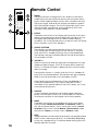
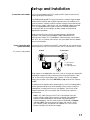
Operating Manual
Mark Levinson®
Nº38
Preamplifier
Madrigal Audio Laboratories, Inc.
WARNING: TO REDUCE THE RISK OF FIRE OR ELECTRIC SHOCK, DO
NOT EXPOSE THIS APPLIANCE TO RAIN OR MOISTURE.
CAUTION
RISK OF ELECTRIC SHOCK
DO NOT OPEN
CAUTION: TO REDUCE THE RISK OF ELECTRICAL SHOCK, DO
NOT REMOVE COVER. NO USER-SERVICEABLE PARTS INSIDE.
REFER SERVICING TO QUALIFIED PERSONNEL.
The lightning flash with arrowhead symbol, within an equilateral triangle, is intended
to alert the user to the presence of uninsulated “dangerous voltage” within the
product’s enclosure that may be of sufficient magnitude to constitute a risk of electric
shock to persons.
The exclamation point within an equilateral triangle is intended to alert the user to the
presence of important operating and maintenance (servicing) instructions in the literature
accompanying the appliance.
Marking by the “CE” symbol (shown left) indicates compliance of this device with the EMC
(Electromagnetic Compatibility) and LVD (Low Voltage Directive) standards of the
European Community.
NOTICE
This equipment has been tested and found to comply with the limits for a Class B digital device, pursuant to Part 15 of the
FCC Rules. These limits are designed to provide reasonable protection against harmful interference in a residential
installation. This equipment generates, uses and can radiate radio frequency energy and, if not installed and used in
accordance with the instructions, may cause harmful interference to radio communications. However, there is no guarantee
that interference will not occur in a particular installation. If this equipment does cause interference to radio or television
reception, which can be determined by turning the equipment on and off, the user is encouraged to try to correct the
interference by one or more of the following measures:
•
•
•
•
Reorient or relocate the receiving antenna;
Increase the separation between the equipment and the receiver;
Connect the equipment into an outlet on a circuit different from that to which the receiver is connected;
Consult the dealer or an experienced radio/TV technician for help.
CAUTION: Changes or modifications to this equipment not expressly approved by the manufacturer could void the user’s
authority to operate the equipment.
Important Safety Instructions
Please read all instructions and precautions carefully and completely before operating your Nº38
Preamplifier.
1. ALWAYS disconnect your entire system from the AC mains before connecting or disconnecting
any cables, or when cleaning any component.
2. This product is equipped with a three-conductor AC mains power cord which includes an earth
ground connection. To prevent shock hazard, all three connections must ALWAYS be used. If
your electrical outlets will not accept this type of plug, an adapter may be purchased. If an
adapter is necessary, be sure it is an approved type and is used properly, supplying an earth
ground. If you are not sure of the integrity of your home electrical system, contact a licensed
electrician for assistance.
3. AC extension cords are not recommended for use with this product. If an extension cord must
be used, be sure it is an approved type and has sufficient current-carrying capacity to power
this product.
4. NEVER use flammable or combustible chemicals for cleaning audio components.
5. NEVER operate this product with any covers removed.
6. NEVER wet the inside of this product with any liquid.
7. NEVER pour or spill liquids directly onto this unit.
8. NEVER block air flow through ventilation slots or heatsinks.
9. NEVER bypass any fuse.
10. NEVER replace any fuse with a value or type other than those specified.
11. NEVER attempt to repair this product. If a problem occurs, contact your Mark Levinson® retailer.
12. NEVER expose this product to extremely high or low temperatures.
13. NEVER operate this product in an explosive atmosphere.
14. ALWAYS keep electrical equipment out of the reach of children.
15. ALWAYS unplug sensitive electronic equipment during lightning storms.
From all of us at Madrigal Audio Laboratories, thank you for choosing
the Mark Levinson® Nº38 Preamplifier.
A great deal of effort went into the design and construction of this
precision device. Used properly, it will give you many years of
enjoyment.
4
Table of Contents
Unpacking and Placement ........................................................................ 7
Placement ............................................................................................. 7
Ventilation .............................................................................................. 7
Unpacking .............................................................................................. 7
Nº38 bottom-panel label ............................................................................ 8
Operating Voltage ...................................................................................... 8
A Quick Start… ............................................................................................ 9
Front panel ................................................................................................. 10
Rear panel ................................................................................................. 12
Biamplification ..................................................................................... 13
Linking Connections ..................................................................... 14
Using a turntable ................................................................................. 15
Tip polarity for External IR input ................................................... 15
Remote Control ......................................................................................... 16
Connections and cables ................................................................... 17
Power connection and system activation ....................................... 17
Set-up and Installation ............................................................................. 17
Aliases ................................................................................................... 18
Available Input Aliases ................................................................. 18
Set-Up Overview .................................................................................. 18
The EQ Alias ......................................................................................... 19
Programming Aliases .......................................................................... 19
Assigning Record Outputs .................................................................. 19
Results of unrealistic tests .................................................................... 20
Programming Input Offsets ................................................................ 21
Programming an Automatic Output Level ...................................... 22
Programming the Mute Function ...................................................... 23
Volume Lock ........................................................................................ 24
Standby Timer ...................................................................................... 25
Time-outs in the Nº38 ........................................................................... 25
Operational Modes ................................................................................... 26
The Monitor Mode ............................................................................... 26
The Record Select Mode ................................................................... 26
The Balance Mode ............................................................................. 27
Balance control tip ............................................................................. 27
Using Surround Sound Processors ............................................................ 28
Surround sound processors should not come after the preamp .. 28
Surround sound processors should not come before the preamp 28
Surround sound processors should not be in a tape loop .............. 29
Surround sound processors and the Nº38 ........................................ 29
Wiring Diagram with a Surround Sound Processor .................... 29
Noise in A/V systems ........................................................................... 30
Ground Isolation Adaptor ............................................................ 30
Display Intensity ................................................................................... 31
Standby Link ......................................................................................... 31
Input Selection ..................................................................................... 31
Record Link .......................................................................................... 31
Linked Functions ........................................................................................ 31
Care and maintenance ........................................................................... 32
U.S and Canadian Warranty .................................................................... 33
Obtaining Service ..................................................................................... 34
Specifications ............................................................................................ 35
Dimensions ................................................................................................. 36
5
6
Unpacking and Placement
Unpacking
Unpack your Nº38 Preamplifier and keep all packing materials for
future transport. Locate and remove all accessory items from the
cartons. Accessories include:
1
1
1
1
2
90° shielded AC power cord
Nº38 remote control
5⁄64" Allen key
1⁄8" Allen key
alkaline batteries for the remote control
Carefully inspect the product for damage and flaws. If you find any,
see your Mark Levinson dealer immediately.
Installing the batteries in
the remote control
Using the supplied 5⁄64" Allen key, remove the two screws in the bottom
end cap of the remote control (i.e., the end opposite the IR transmitter
lens). Insert the two alkaline batteries found in the Accessories box,
being careful to follow the polarity indications given on the inside of
the battery compartment. Replace the end cap and the screws, using
the Allen key.
If you notice that your remtoe control seems not to be performing as
well as it once did, its batteries are probably running low. Check the
batteries periodically, and replace batteries before they are “dead.”
(Fully dicharged batteries are prone to leaking corrosive chemicals—
the greenish “gunk” you may have seen around battery terminals of
other remote controls at some point.)
Placement
The Nº38 should be placed close to your source equipment, keeping
interconnect cabling short. We strongly recommend shelf mounting to
allow for proper ventilation.
The Nº38 is designed for continuous operation, which is why it features
a standby mode rather than a full “off” mode—it is designed to be
connected to the AC mains at all times for the best performance.
Ventilation
Be sure to allow 3 to 4 inches of clearance above the Nº38 to allow
heat dissipation through air circulation.
Drawings are included in this manual to facilitate special installations
and custom cabinetry (see “Dimensions”).
PRECAUTION
For your protection, review “Important Safety Instructions” before you
install your Nº38.
It is extremely important that all components in your system be
properly grounded. Under no circumstances should you defeat
a three-prong AC cord with a “ground-lifter” or “cheater”
adaptor, as doing so may allow dangerous voltages to build up
between components. The presence of these voltages would
pose a threat to both your person and your equipment.
7
Operating Voltage
The Nº38 Preamplifier is set at the factory (internally) for 100V, 120V,
200V, 230V, 220V, or 240V AC mains operation @ 50 or 60Hz. (230V/
50Hz only in European Union countries, in compliance with CE
regulations.) This voltage setting cannot be changed by the user.
Make sure that the label on the bottom panel of the Nº38 (adjacent to
the AC cord) indicates the correct AC operating voltage for your
location.
If the voltage indicated on your Nº38 is incorrect, or if you wish to
change the AC operating voltage of your Nº38 as the result of moving
to a different country than the one in which you purchased your
digital audio processor, see your Mark Levinson dealer.
The Nº38 can be powered by a normal 15-ampere AC mains line. If
other devices are also powered from the same AC line, their
additional power consumption should be taken into account.
8
A Quick Start…
We recognize that many people are understandably eager to begin
listening to their new components, and that reading the manual is
often done (if at all) at a later time—perhaps while listening to music
through the new product itself. We strongly recommend that you read
this manual thoroughly, as the Nº38 Preamplifier incorporates many
unusual features which enhance its operation.
Fortunately, we can help you get some music up and running on your
system quickly, so that you may begin enjoying your new preamplifier
while reading more about it. The goal here is simply to make some
music as quickly as possible.
The following procedure assumes that the rest of your system is already
connected (e.g., power amplifier to speakers, etc.).
1
TURN OFF YOUR ASSOCIATED COMPONENTS
This minimizes the opportunity for a momentary electrical surge
disturbing your system while making connections. If you have a
large power amplifier, allow its power supply to fully discharge
before proceeding (which may take as long as fifteen minutes).
2
PLUG THE Nº38 INTO THE WALL OUTLET
Connect the AC cord to the male IEC connector on the center of
the bottom panel of the Nº38, then connect the AC cord to the
AC mains. When power is first applied, the Nº38 will initialize
(showing all current input aliases), automatically select the first
available input (AUX1), and set its output level to OFF.
3
CONNECT A SOURCE TO INPUT 1 (INPUT 3 IF SINGLE-ENDED)
Connect the output of your source with the Left and Right Input 1
XLR jacks on the rear panel of your Nº38 preamplifier. (Use the
Input 3 RCA jacks if your source is single-ended. If used, press the
Input 3 button on the face of the Nº38 to select this input.) High
quality interconnecting cables such as Madrigal HPC will yield
superior results, and are strongly recommended.
4
CONNECT THE Nº38 OUTPUTS TO YOUR POWER AMP
The Left and Right Main Out jacks on the rear panel of the Nº38
should be connected to the corresponding inputs of your power
amplifier. If your power amplifier has balanced inputs and you
have appropriate high-quality cables (with XLR plugs at both
ends), we recommend using the Balanced Main Outs. Otherwise,
use the (single-ended) Main Outs from the preamplifier to your
power amplifier. Once again, high quality interconnecting cables
such as Madrigal HPC will yield superior results, and are strongly
recommended.
5
TURN ON YOUR SOURCE COMPONENT
6
TURN ON YOUR POWER AMPLIFIER
7
SLOWLY RAISE THE VOLUME ON THE Nº38 TO A COMFORTABLE LEVEL
Congratulations! You should now be able to enjoy your favorite
music while reading the rest of this manual.
9
1
2
3
4
5
6
display
intensity
R
inverted
mode
polarity
MADRIGAL AUDIO LABORATORIES
PREAMPLIFIER
Nº 38
monitor
mono
1
record select
2
3
7
balance
4
5
6
8
mute
9
standby
10
Front panel
1
DISPLAY INTENSITY BUTTON
Cycles among four levels of brightness (including “off”) for the
display, allowing adjustment for various ambient lighting
conditions. When “off,” the display will turn on for a few seconds
whenever a setting is changed. When used in conjunction with
certain compatible Mark Levinson components, this button will
control the display intensity of all linked components. (For more
information, see “Linked Functions.”)
2
ALPHANUMERIC DISPLAY
Provides a wide range of information concerning the operational
status of the Nº38. The information displayed depends on the
operating mode the Nº38 is in at any point in time. The information
displayed is summarized below:
Monitor
Record Select
Balance
Selected (audible) Source and Volume
“RECD” and Source to be recorded
Direction and Magnitude of Offset
In addition, when used with Mark Levinson power amplifiers that
incorporate our communications link circuitry, this display is used to
indicate the presence of a fault condition (if any) in the amplifier.
Please refer to the owner’s manual of your amplifier for more
information. For more detailed information on the preamplifier’s
use of this display, see “Operational Modes.”
10
3
MODE INDICATORS
Three LEDs give visual confirmation of the Operational Mode the
Nº38 is in at any moment.
4
MODE BUTTON
Cycles among the three primary Operational Modes of the Nº38:
Monitor (the source being listened to); Record Select (the source
being provided to the Record Outputs); and Balance (the relative
volumes of the Left and Right channels). Confirmation of these
operating modes is given by the Mode Indicators below the
Alphanumeric Display. (See 3, above.)
5
INVERTED POLARITY INDICATOR
The polarity (sometimes inaccurately called “absolute phase”) of
the output of the Nº38 may be inverted via the Nº38 remote
control, in which case this LED will light as confirmation. A second
press of the Polarity button on the remote control will restore the
polarity of the output to its original, non-inverted state.
6
OUTPUT LEVEL
This control is normally used to adjust the listening volume, and
does not effect the level of the signal being sent to the Record
Outputs. When in Balance Mode, this knob is used to vary the
relative output of the Left and Right channels. It is also used during
set-up for various adjustments; see “Set-up and Installation.”
7
MONO BUTTON
This button toggles between Stereo and Mono operation. When in
Mono, it activates circuitry which combines Left and Right input
signals, and sends the resulting monophonic signal to both Left
and Right outputs. This circuit is particularly useful when listening to
older, monophonic source material, at which time significant noise
reduction may be realized.
8
SOURCE SELECTOR BUTTONS
Inputs 1–6 are selected by pressing their respective buttons. When
in the Monitor Mode, pressing one of these buttons will select the
source to be heard (i.e., sent to the main outputs); when in Record
Select Mode, pressing one of these buttons will select the source to
be recorded (i.e., sent to the record outputs).
9
MUTE BUTTON
Pressing the Mute button will reduce the main output level of the
preamplifier by a user-modifiable amount, ranging from 1 to 60
decibels. Pressing the Mute button a second time without adjusting
the volume will return it to its previous setting. If you adjust the
volume with either the output control knob or the remote control
while in the Mute mode, the preamplifier will adjust its volume from
the muted volume and disengage the Mute function. The factory
default setting of the Mute circuit is -20 dB. (See “Set-up and
Installation” for information on changing the factory default
setting.)
10 STANDBY BUTTON
Toggles the Nº38 between normal operation and Standby, wherein
the display is turned off, the outputs are disconnected, and all
controls are inoperable. All critical circuitry remains powered-up
during Standby to ensure immediate, optimal performance when
you are ready to listen to music. The LED above the Standby
button will blink slowly when the Nº38 is in Standby, indicating that
power is still being provided to the unit. (If the Nº38 is Linked to
other Mark Levinson components which are also in Standby, they
will blink in unison.)
11
1
2
3
4
right
rec out 1
5
4
c o m m u n i c a t i o n
slave
external
right
rec out 2
p o r t s
master
left
rec out 2
left
rec out 1
PREAMPLIFIER Nº38
designed and manufactured in U.S.A.
by
right balanced
main out
right balanced
input 1
right balanced
input 2
PUSH
PUSH
right main out
MADRIGAL
left balanced
input 2
right
input 3
right
input 4
right
input 5
7
6
right
input 6
left
input 6
7
left
input 5
6
left
input 4
left
input 3
PUSH
S/N
left balanced
input 1
left balanced
main out
PUSH
left main out
3
2
1
Rear panel
PRECAUTION
Disconnect all associated equipment from the AC mains BEFORE
making any signal connections and applying power to the Nº38.
Note: All left-channel inputs and outputs are on the left of the rear
panel as seen from the front, and all right-channel inputs and outputs
are on the right of the rear panel as seen from the front. This design
minimizes any possible confusion when changing connections once
the unit is installed, while maximizing channel separation in this dual
monaural preamplifier.
1
BALANCED MAIN OUTPUTS
If your power amplifier is equipped with balanced (sometimes
called “differential”) inputs, it is best to use these balanced outputs
on your Nº38. A balanced signal from preamplifier to power
amplifier will offer the highest possible performance with the best
immunity from common-mode noise, such as radio frequency
interference (RFI). The balanced output signal is made available
by way of precision male XLR connectors (requiring female XLRs on
the preamplifier end of the interconnecting cable).
The pin assignments of these XLR-type male outputs are:
1 2
3
Pin 1: Signal ground
Pin 2: Signal + (non-inverting)
Pin 3: Signal – (inverting)
Connector ground lug: chassis ground
Refer to your power amplifier’s operating manual to verify that the
pin assignments of its input connectors correspond to the Nº38. If
not, wire the cable so that the appropriate output pin connects to
the equivalent input pin.
Connect the right-channel and left-channel Balanced Main
outputs of the Nº38 to the appropriate balanced inputs of the
power amplifier.
12
If your system calls for multiple outputs from the Nº38 (as might be
the case for “passive” biamplification, for example), you may use
balanced Y-adaptors to split each balanced output into two
balanced outputs. The low output impedance (6Ω) of the Nº38
can easily drive multiple power amplifiers.
Biamplification
2
SINGLE-ENDED MAIN OUTPUTS
Single-ended (“unbalanced”) outputs are provided for
compatibility with a wide range of associated components,
including power amplifiers and electronic crossovers.
If you use the single-ended outputs, connect them to the
corresponding inputs of your power amplifier (or other device).
Note that special features of the Nº38 enable it to be used
optimally with a surround sound processor as one of its inputs. We
do not recommend having a surround sound processor follow the
Nº38 in the signal path. (For more information, see “Using Surround
Sound Processors.”)
3
BALANCED INPUTS 1 AND 2
Accepts right-channel and left-channel balanced signals from
source equipment with balanced outputs.
The pin assignments of these XLR-type female input connectors
are:
PUSH
2 1
3
Pin 1: Signal ground
Pin 2: Signal + (non-inverting)
Pin 3: Signal – (inverting)
Connector ground lug: chassis ground
Refer to the operating manuals of your balanced-output line-level
sources to verify that the pin assignments of their output
connectors correspond to the Nº38. If not, wire the cables so that
the appropriate output pin connects to the equivalent input pin.
Note: If you won’t be using the Nº38’s balanced inputs and
need more single-ended inputs, it’s possible to fabricate a
cable to connect line-level sources with single-ended output
to these balanced inputs:
1
22-gauge
buss wire
Male RCA
(connect to source)
4
2
3
Male XLR
(connect to Nº38)
RECORD OUTPUTS
Connect these outputs to the right-channel and left-channel tape
inputs of your recorder.
These outputs are unaffected by the OUTPUT LEVEL control on the
front panel of the Nº38, or by the source chosen to be Monitored.
13
5
SLAVE AND MASTER COMMUNICATOR PORTS
These communications ports allow the Nº38 to “link” to certain
compatible Mark Levinson components. (See “Linked Functions.”)
The Mark Levinson Linking system uses a Digital Audio Processor as
the Master of (and central clearinghouse for) inter-component
communications. Other components such as digital transports are
connected to the Master as “Slaves,” and can be “daisy-chained”
using their Slave In and Slave Out jacks. As the ultimate destination
of all source signals, the Nº38 Preamplifier must be the final “Slave”
in the chain. (In technical terms, it terminates the communications
buss.) In turn, the Nº38 can serve as a master to an associated
compatible Mark Levinson power amplifier—hence its “Master”
communications port.
Thus, if the only other Mark Levinson Link-compatible component
you have is a digital audio processor, connect its master port to
the Nº38’s slave port using a “straight-through” RJ-45 cable. If there
are additional Mark Levinson Link-compatible components in the
system, place the Nº38 at the end of the chain by connecting the
last slave out port to the Nº38’s slave port. See the diagram below
for clarification.
Linking Connections
Nº30
OR
analog output
Nº35
digital input
master
Audio
connections
Link
cable
digital output
slave in
Nº31
slave out
Link
cable
digital output
slave in
Nº31
slave out
Link
cable
any input
slave
Nº38
master
Link
cable
slave in
R
R
MADRIGAL AUDIO LABORATORIES
MADRIGAL AUDIO LABORATORIES
REFERENCE
MONAURAL
AMPLIFIER
Nº 33
slave in
14
REFERENCE
MONAURAL
AMPLIFIER
Nº 33
Link
cable
slave out
The RJ-45 cable needed for the Link connection between source
components and the preamplifier may be purchased from your
Mark Levinson dealer. It may also be easily and inexpensively
made to length using two RJ-45 connectors and the appropriate
length (up to 100 feet/30 meters) of RJ-45 (flat, eight conductor)
cable.
RJ-45 cables and connectors are used throughout the world for
both telecommun-ications and computers, and are widely
available at low cost. The connectors are crimped on to the ends
of the cable such that pin 1 at one end is connected to pin 1 at
the other end. Such a “straight-through” connection is (counterintuitively) made by introducing a 180° twist in the cable between
the two ends, as shown below.
To Mark Levinson®
digital processor
Building a Link cable
Locking tab
To Nº38
180° twist
Locking tab
The power amplifier Link connection is made using a 6-conductor
Link cable. Connect the Nº38’s master port to the slave port of a
compatible Mark Levinson power amplifier.
Connecting the communication ports other than as
described in this manual will damage the Nº38 and the
associated Mark Levinson components, and will void those
products’ warranties.
PRECAUTION
6
INPUTS 3-6
Accepts right-channel and left-channel (single-ended) inputs from
line-level source equipment such as tuners, CD players, and tape
decks.
If a turntable is to be used with the Nº38, it must be used in
conjunction with a phono preamp such as the Mark Levinson Nº25
which will handle RIAA equalization and which will deliver a linelevel signal to the input of the Nº38.
Using a turntable
7
EXTERNAL IR INPUT
The Nº38 incorporates an infrared repeater input to facilitate a
wide range of installation options. If desired, the Nº38 may be
placed inside a cabinet or outside the normal line-of-sight in the
listening area, with the controlling IR signal being relayed to the
Nº38 by any of a number of commercially-available IR repeaters.
The specifications for this IR input call for a triggering voltage of
5 volts at no more than 100 milliamps of current, with the tip of the
1⁄8" mini-plug having positive polarity, as below:
–
Tip polarity for
External IR input
+
5 volts @ less
than 100 mA
If you would like more information on the possibility of using an
infrared repeater with your Nº38, please contact your Mark
Levinson dealer.
15
Remote Control
R
MADRIGAL AUDIO LABORATORIES
1
2
3
4
5
mono
polarity
display
mode
1
2
3
4
5
6
volume
mute
1
MONO
Pressing this button will toggle the Nº38 in and out of the Mono
mode, having the same effect as pressing the front panel mono
button. Mono mode activates circuitry which combines Left and
Right input signals, and sends the resulting monophonic signal to
both Left and Right outputs. This circuit is particularly useful when
listening to older, monophonic source material, at which time
significant noise reduction may be realized.
2
DISPLAY
Duplicates the function of the Display Intensity button on the front
panel, cycling among four levels of brightness (including “off”) for
the display, allowing adjustment for various ambient lighting
conditions. (Tip: If pressed and held for several seconds, the Display
button will place your Nº38 in Standby.)
3
SOURCE SELECTION
These buttons provide remote selection of the six inputs of the
Nº38. Pressing any of these buttons (or the Volume +/- buttons)
while the Nº38 is in Standby will bring it fully on and operational.
These buttons are gray instead of black to serve as a reminder of
this secondary function.
4
VOLUME +/Raises the volume at either low speed for fine adjustments or high
speeds for larger changes. The Nº38 will slowly raise its output for
the first 1.5 seconds this button is depressed, then move to higher
rates of change.
6
7
Pressing either Volume +/- button while the Nº38 is in Standby will
bring it fully on and operational. These buttons are gray instead of
black to serve as a reminder of this secondary function.
Note that all volume and balance functions are disabled if a
surround sound processor [“ssp”] input is selected. For more
information on this special feature of the Nº38’s design, see “Using
Surround Sound Processors.”
16
5
POLARITY
Inverts the polarity (sometimes inaccurately called “absolute
phase”) of the outputs of the Nº38. A second press of this button
will restore the outputs to their original, non-inverting polarity.
6
MODE
Duplicates the function of the Mode button on the front panel,
cycling through Monitor, Record Select, and Balance modes. As
with the front panel button, use it in conjunction with the Source
Selection buttons when in either Monitor or Record Select mode
and with the Volume +/- buttons when in Balance mode.
7
MUTE
Toggles between normal output level and the user-programmable
Mute function, reducing the level by 1 to 60 decibels (depending
on the user’s programming). The factory default setting gives a 20
decibel reduction in output.
Set-up and Installation
Connections and cables
The Nº38 incorporates both RCA-type and XLR-type connectors for
audio signal input and output.
The Madrigal-designed RCA-type connectors used for single-ended
audio interconnection are a great improvement over ordinary RCAtype connectors, offering superior contact integrity and mechanical
locking when used in conjunction with the Madrigal cable-mounted
RCAs. The gold-plated XLR-type connectors used for balanced
connections are of Swiss design, and are made to professional
application standards.
When connecting the Nº38 to source equipment and power
amplifiers, we recommend Madrigal Audio Laboratories HPC
Interconnect Cable. HPC is available in various lengths, terminated
with RCA, XLR, or Camac connectors. See your Mark Levinson dealer
for more information.
Power connection and
system activation
AC power cord polarity
Connect the AC cord to the male IEC connector on the center of the
bottom panel of the Nº38, then connect the AC cord to the AC mains.
To Nº38
To AC mains
1
2
3
2
1
1 = Line (hot)
2 = Neutral
3 = Earth ground
3
When power is first applied to the Nº38, it will run through an automatic
initialization sequence which (among other things) provides a “rolecall” of the current input aliases (see “Aliases” on the next page),
selects the first alias other than NOT USED or ssp, and sets the volume
to OFF.
For optimal sonic performance and longevity, the Nº38 is designed to
remain powered at all times (the Standby switch merely mutes the
preamplifier’s outputs and turns off the display). There is an initial
break-in period of 300 hours before the Nº38 achieves optimum
performance.
Note: If AC mains power to the Nº38 is interrupted, the main
output will be muted. When power is restored, the initialization
sequence described above will restore the preamplifier to
normal operation, with the main output muted and the Display
indicating OFF. We recommend you allow the circuitry within
your various system components to stabilize for 1 to 2 minutes
before use after such a power outage.
17
Set-Up Overview
The Nº38 Preamplifier has many provisions for custom-tailoring the
system’s operation to match your preferences. The consistent method
for modifying any of these settings is to enter a Set-Up mode by
pressing and holding a button for several seconds; the setting is then
modified, either by pressing a button or turning the volume knob; and
then the new preference is confirmed by pressing and holding the
original button again for several seconds.
This three-step process is simple and logical, yet ensures that changes
which affect the operation of the preamplifier must be made quite
deliberately.
Aliases
Available Input Aliases
To facilitate operation in complex multi-source systems, the Nº38 is
capable of displaying a wide variety of aliases, or alternative names,
for each of its six inputs. They are listed below.
NOT USED
ssp
EQ
DAT
VCR
CAS
RTR
DCC
MD
CDR
CDI
DBS
PH
LD
CD
TUN
AUX
DAP
DCA
PCD
PDP
No30
No35
(any unused input)
Surround Sound Processor
Equalizer
Digital Audio Tape
Video Cassette Recorder
Cassette
Reel-To-Reel
Digital Compact Cassette
Mini-Disc
Compact Disc, Recordable
Compact Disc, Interactive
Direct Broadcast Satellite
Phono
LaserDisc
Compact Disc
Tuner
Auxiliary
Digital Audio Processor
Digital Cable Audio
Proceed Compact Disc Player
Proceed Digital Audio Processor
Mark Levinson Nº30 Digital Audio Processor
Mark Levinson Nº35 Digital Audio Processor
Each alias is normally followed by a number corresponding to the
number of the input being used. (The exceptions being the aliases
“No30” and “No35” for the corresponding Mark Levinson digital audio
processors.) Thus, a DAT in Input 3 would normally display a DAT3. In
this way, you can have more than one CD player, for example, and
still tell at a glance which one is selected.
There is also a special alias to indicate that an input is NOT USED.
The factory default input alias is NOT USED for each input except AUX1
and AUX3, which were configured for the Quick Start portion of this
manual. Any or all input aliases (including these) may be changed
easily to match the configuration of your particular system.
18
The EQ Alias
The EQ alias also deserves special mention: if your loudspeaker
requires a dedicated equaliser for proper operation (or if you have
any other reason for using an EQ much of the time), you may connect
the outputs of the equalizer to the input named “EQ.” By “recording”
the source you wish to listen to (selecting it on the record path), and
montioring the EQ input, you will be able to run all signals through the
equalizer prior at a line level. This is usually preferable to simply placing
the EQ between the preamp and the power amp, as most equalizers
perform best at a (fixed) line level.
Since, in this scenario, you would spend most of your time in the record
path (selecting the source to be equalized) rather than the monitor
path, we have enabled the volume control function in the record
path when the input selected on the monitor path is named EQ. Thus,
you may adjust the volume of the selected source without having to
push the mode button twice to return to the monitor path.
Programming Aliases
Assigning Record Outputs
To change the alias of any particular input, follow these steps:
1
IN THE MONITOR MODE, SELECT THE INPUT YOU WISH TO RENAME
2
PRESS AND HOLD THE MODE BUTTON…
on the front panel until the display reads SET DATA, as below:
3
RELEASE THE MODE BUTTON; PRESS THE CHOSEN INPUT BUTTON
REPEATEDLY…
until the Alias you desire appears in the display.
4
PRESS AND HOLD THE MODE BUTTON AGAIN…
until the display reads NEW DATA, as shown below. (Note: see Step
5 below if you have selected an alias of a device capable of
recording.) This indicates that your new alias for that input has
been stored in non-volatile memory. As a result, this new setting
will survive power outages and other interruptions of AC power to
the preamp.
5
IF YOUR ALIAS MAY REQUIRE AN INPUT…
You will be further prompted to associate a particular Record
Output with this particular device. Instead of showing “NEW DATA,”
the Display will read “RCD: NONE” as shown below.
19
You may elect not to use either Record Output with this particular
device, as may be the case if you have several devices in your
system that are capable of recording. In this case, leave the
display on “RECD NONE” and move to Step 6.
You may also select either Record Output 1 or 2 to be associated
with this particular input. To do so, press the input button
repeatedly until you see your choice of OUT1 or OUT2 in the
display. (OUT1 is given as an example on the next page.)
Results of unrealistic tests
6
STORE YOUR SELECTION
Save your choice in non-volatile memory by pressing and holding
the Mode button until the display reads NEW DATA, as below.
Note: The Nº38 Preamplifier has been optimized to yield optimum sonic
performance under normal, real-world operating conditions. This
approach involves no disadvantage when the unit is used as
designed.
Unrealistic tests such as listening at full gain to an unterminated input
which has been associated with an unterminated record output may
result in some small amount of noise at the main output which does
not occur when the Nº38 is used correctly. Moreover, even under
these unrealistic test conditions, any resulting noise is small and poses
no danger.
Rather than compromise the sonic performance of the preamplifier in
an effort to eliminate even the remote possibility of this noise being
detected, the set-up procedure outlined above for programming
input aliases was designed to make it virtually impossible to create a
condition under which any such noise can be heard. We recommend
using the input alias NOT USED for all unused inputs.
20
Programming Input Offsets
The Nº38 allows you to adjust the relative outputs of your various
sources with respect to one another, so as to avoid disturbing and/or
potentially dangerous changes in output levels as you switch from one
source to the next. These Input Offsets are made relative to whichever
source tends to be the loudest—that is, you raise the outputs of the
remaining sources to match that of your loudest source. This is
achieved as follows:
1
DECIDE WHICH SOURCE HAS THE HIGHEST OUTPUT
You should listen to several examples of each source before you
decide (e.g., to several different CDs when evaluating your CD
player’s output, or to several radio stations when evaluating your
tuner’s output). The point is to ascertain whether any source
consistently plays more loudly than others, and to bring the others
up to its level. (For example, other things being equal, balanced
outputs of components are usually approximately 6 dB stronger
than the single-ended outputs.)
2
LISTEN TO THIS SOURCE LONG ENOUGH TO ESTABLISH ITS VOLUME
Use a particular output level setting to which you can easily return,
such as 60.0 in the display. Develop a sense of the perceived
volume at this setting, which you will want to match with your other
inputs. Optionally, you may desire to measure its actual output at
your chosen volume setting with a sound pressure level (SPL) meter
set to “Slow” or “Average” response.
3
SELECT THE FIRST OF THE SOURCES WHOSE OUTPUT YOU WILL RAISE
While music is playing from both your reference, “loudest” source
and the source you are about to adjust, select the latter so as to
give you a sense of the magnitude of the adjustment you are
about to make.
4
PRESS AND HOLD THE MODE BUTTON ON THE FRONT PANEL
After a few seconds the display will change to show SET DATA, as
below. Release the Mode button.
5
RAISE THE VOLUME TO MATCH YOUR REFERENCE
Using the volume knob, raise the volume of your “quieter” source
until it subjectively matches the volume level of your “loudest”
source. The display will show the alias of the input you are adjusting
and the degree of additional output you are assigning to it,
measured in decibels (0.0 to 20.0 dB in tenths of a decibel).
Note that “CD 1” in the example given above represents the
21
currently chosen input, and “2.8” indicates the current offset for
that input.
6
PRESS AND HOLD THE MODE BUTTON AGAIN…
until the display reads NEW DATA, as below.
This indicates that your new Input Offset has been stored in nonvolatile memory. As a result, this new setting will survive power
outages and other interruptions in AC power to the preamp. You
may wish to repeat this process in order to refine your settings.
Programming an
Automatic Output Level
The Nº38 also features the ability to remember a “preferred” output
level setting, to which it will return whenever you select a particular
input. This capability is a great convenience when used with tuners, for
example, since their output level is often more consistent than other
sources, and since tuners may be used primarily for background
(rather than critical) listening. This adjustment may be made for each
input independently of any other input.
In order to take advantage of this Automatic Output Level setting,
follow the steps below:
1
SELECT THE INPUT WHOSE LEVEL YOU WOULD LIKE TO “AUTOMATE”
2
ADJUST THE VOLUME TO YOUR PREFERRED LEVEL
This will be the preferred, programmed level.
3
PRESS AND HOLD THE MODE BUTTON ON THE FRONT PANEL
Hold the Mode button until the display reads “SET DATA,” as below:
4
TURN THE VOLUME KNOB COUNTER-CLOCKWISE FROM 0.0 UNTIL THE
DISPLAY READS “AUTO”
The display will initially look like the illustration below:
When the volume knob is rotated counter-clockwise, the display
will change to resemble the illustration shown at the top of the next
page.
22
In effect, you are setting the Input Offset of this input to remember
an absolute volume setting (whatever it was before you held the
Mode button down) rather than a relative setting (that is, relative
to the current playback volume).
5
PRESS AND HOLD THE MODE BUTTON AGAIN…
until the display reads NEW DATA.
This indicates that your new Automatic Output Level has been
stored in non-volatile memory. Your Nº38 will now automatically
return to this volume setting whenever this input is selected. To
reverse this situation, simply re-adjust the Input Offset as described
above (in “Programming Input Offsets”).
IPRECAUTION
MPORTANT
Programming
the Mute Function
Note: It is necessary for the Nº38 to have an Input Offset of 0.0 in
order to access the AUTO setting. As a result, it will be necessary
to save a 0.0 Input Offset before selecting AUTO if a higher offset
was previously saved.
The Nº38 provides a user-defined Mute function which instantly
reduces the output level by a predefined amount between 1 and 60
decibels. The factory default setting is -20 dB. If you regularly listen at
relatively high sound pressure levels, you may wish to increase the
magnitude of the change brought about by engaging the Mute
function. For example, a -20 dB change from an average of 95 dB SPL
would bring the volume in the room down to 75 dB SPL. If used in
response to the telephone ringing, you would probably find 75 dB SPL
of music in the background too loud for a comfortable telephone
conversation. To alter the change introduced by the Mute function:
1
PRESS AND HOLD THE MUTE BUTTON
Wait until the Display reads “MUTE” and a number (which will read
“-20” as delivered from the factory).
23
2
ADJUST THE VOLUME KNOB TO YOUR PREFERRED SETTING
You may select any value between -1 and -60 decibels (inclusive),
in one-decibel increments.
3
PRESS AND HOLD THE MUTE BUTTON AGAIN
When the display reads NEW DATA, the Nº38 will have saved your
new setting in non-volatile memory.
The Mute button will toggle you back and forth between the “Normal”
playback level and a level which is as many decibels below that level
as you have elected to use as your Mute function. However, if you
adjust the volume with either the output control knob or the remote
control while in the Mute mode, the preamplifier will adjust its volume
from the muted volume and disengage the Mute function. This design
guards against unexpected, large increases in volume which might
cause inadvertent damage to your loudspeakers.
Volume Lock
The Nº38 also allows a “maximum volume setting” to be established.
Using this feature, it now becomes possible to “lock out” volume
settings above a certain point in the preamplifier’s range.
In systems that have highly sensitive loudspeakers, the available +18.9
dB of gain may allow the system to be driven to dangerously loud
levels. Alternatively, the presence of children in the home may lead
the owner of the system to desire some restriction on how loudly it can
be played.
In either case, setting the maximum volume is quite simple:
1. turn the volume to the desired “maximum volume”
2. press and hold the mono button until the display reads LOCK SET
The display will time out after a few seconds and revert to its normal
display, except that it will no longer allow you to exceed the chosen
maximum volume. (Exception: the SSP mode will still override this
feature and pass the surround processor’s front channels through at
unity gain, regardless of the setting of the Volume Lock.)
If and when you want to restore the volume control to its normal, full
range operation, simply press and hold the mono button again to
toggle back into the normal volume mode of operation. The display
will read LOCK OFF to indicate the return to normal operation.
24
Standby Timer
In a similar fashion, the user of a Nº38 or Nº38S can elect to have the
preamplifier (and the entire system, if Linked) go into standby after a
certain period of time, much like a “Sleep Timer” on many alarm
clocks. To engage the Standby Timer on the Nº38/S:
1. press and hold the standby button until the display reads TIME
OFF.
2. turn the volume knob to select a time between 1 and 120
minutes. (Example: TIME 60 would turn off the system in an hour.)
3. the display will now time out and return to normal
4. the preamp (or Linked system) will go into standby at the
appointed time one time only (so you don’t have to live with the
product turning itself off every 60 minutes thereafter…).
Time-outs in the Nº38
IPRECAUTION
MPORTANT
Note: As a fail-safe against accidental changes (perhaps by
smaller children, for example), changes made in various set-up
modes are never made permanent without a second,
confirming action on the users’ part, such as pressing and
holding the Mode button a second time after a change is made.
If a Set-up mode is entered accidentally, the Nº38 will time-out,
or return to normal operation, after approximately ten seconds
of inaction on the users’ part. No changes are made to the
existing set-up when the Nº38 reverts to normal operation via a
time-out.
25
Operational Modes
The Monitor Mode
The majority of time you spend with your Nº38 will be spent in the
Monitor mode. In this mode, the display indicates the alias of the input
you have selected and the listening volume (in decibels). The Output
Control acts as a volume knob, increasing or decreasing the volume in
0.1 dB increments above 39.0 (with gradually increasing increments
below this low level). The Input Selection buttons select the source to
be listened to at any point in time. In short, in the Monitor Mode, the
Nº38 acts precisely as you would expect a preamplifier to act.
There are several refinements which may not be immediately
apparent to the casual user, however. When turned quickly by hand,
the effect of the Output Control will accelerate (i.e., yield a greater
change per revolution of the knob) so as to reach your preferred
volume more quickly. Conversely, when the knob is turned slowly, the
volume changes at maximum resolution to facilitate fine adjustments
and precise level control (0.1 dB through most of the range).
However, if the volume knob is spun quickly (as though it were a
flywheel), the rate of change will decrease again. This design helps
avoid accidental bumps of the preamplifier’s Output Level knob
sending potentially dangerous signal levels to your loudspeakers.
Lastly, the corresponding buttons on the Remote Control behave in a
similar fashion when in the Monitor mode. If the Volume +/- buttons are
held for more than approximately 1.5 seconds, the Nº38 infers that you
would like to change volume more quickly and accelerates the
volume change.
While in the Monitor mode, the Input Selector buttons choose the
source which will be heard over the loudspeakers.
The Record Select Mode
When you wish to send a signal out to be recorded, push the Mode
button once to enter the Record Select mode. In this mode, the
display indicates “RECD” on the left side and the alias of the input
currently being supplied to the Record Outputs on the right. An
example is given below:
To select a different input for recording, simply press the appropriate
Input Selection button while in this mode. Note that the Nº38 will not
allow a recording device to serve as its own source while monitoring
itself, as this would allow potentially dangerous feedback to be
reproduced by the loudspeakers. (See “Programming Input Aliases”
for more details.)
The Record Outputs may be disconnected (or “defeated”) by
pressing the Input Selector button of the currently selected input a
second time. Doing so will toggle the Record Outputs on and off. The
26
display will alternatively read the alias of the chosen input and “RECD
OFF” as shown below.
Defeating the Record Outputs eliminates even the possibility that the
input impedance of a recording device could have an effect on the
sound quality of the preamplifier. We recommend that Record
Outputs be turned OFF when not in use.
The Balance Mode
The Balance mode gives you extremely fine control over the relative
volumes of the Left and Right channels, by changing the volume of
one relative to the other in increments of 0.1 dB, up to 20.0 dB.
(Beyond this point, the Balance control will mute the output of the
reduced channel.) Once set, this inter-channel difference in volume
remains the same regardless of Output Level and selected input, until
it is changed again in the Balance mode, or when AC power is
interrupted (in which case the Balance is reset to 0.0).
To enter the Balance mode from the Monitor mode, press the Mode
button twice (once from the Record Select mode). When the balance
is set to a neutral position, favoring neither channel over the other, the
display will show a double-headed arrow and “0.0” decibels—that is,
that the channels are balanced with respect to one another.
Turning the Output Level control in either direction will change the
balance in that direction. The display will reflect this by changing to
the appropriate single-headed arrow to indicate the direction of
change and by showing the number of decibels by which that
channel has been increased (in tenths of a decibel), as below:
In this example, the Right channel is 2.3 decibels louder than the Left.
Balance control tip
Precise balance control is essential for obtaining accurate soundstaging. Output imbalances due to asymmetrical placement of the
loudspeakers in the room are common, and degrade imaging
accuracy. To correct this problem, place the Nº38 in mono mode and
center the resulting image (which should be quite small) directly
between the loudspeakers, using the Balance control. Differences as
small as 0.1 or 0.2 decibels have been found to be significant. Try it.
27
Using Surround Sound
Processors
The Nº38 Preamplifier incorporates a special surround sound processor
mode which makes it uniquely capable of integrating the highest
performance audio with surround sound—that is, dual-purpose music
and movie systems. In order to better understand the value of this
design, it is essential to understand a bit about the nature of a Dolby
Pro-Logic Surround™ decoder.
The Dolby Stereo® system encodes four discrete channels into a twochannel matrix during the production of the movie soundtrack. This
two-channel signal is compatible with normal stereo (and even
monophonic) playback. With the proper decoding during playback,
however, it is possible to recover the original four channels from the
two which are present on the laserdisc or on the hi-fi videotape. These
channels are Left, Center, and Right in the front, and a single Surround
channel for the sides and rear of the audience. In order to recover all
four channels, it is necessary to have a stereo source (laserdisc, Hi-Fi
videotape and stereo TV being the most common) and an
appropriate decoder.
Surround sound
processors should not
come after the preamp
Surround sound
processors should not
come before the preamp
28
Dolby Pro-Logic decoders incorporate a form of Dolby noise reduction
similar to the Dolby B one finds in cassette decks. This form of noise
reduction is level-sensitive. That is, Dolby noise reduction intentionally
treats strong signals differently than weak signals. In order to operate
correctly, the signal strength of the source must be “calibrated” to the
expectations of the Dolby noise reduction circuitry. (It is for this reason
that one finds “Record Calibration” features on better-quality cassette
decks.) It is therefore inappropriate to feed a surround sound decoder
with the variable output of a preamplifier. Were you to do so, every
change of the volume control on the preamplifier would cause the
Dolby circuitry to mistrack. In extreme cases, severe distortion can
result as the Dolby circuitry overloads.
The next logical alternative might be to use the Pro-Logic decoder
ahead of the preamplifier, sending its Left and Right outputs through
the preamplifier as a selectable Source. Sending the Right and Left
Outputs from a surround sound decoder to a pair of inputs on a
conventional preamplifier is also inappropriate, since any change of
the preamp’s volume control would then throw the carefully
calibrated output levels of the decoder out of adjustment, changing
the volume of the Left and Right speakers while leaving the Center
and Surround speakers unaffected. One could attempt to restore the
proper balance by marking a “calibrated” point on the preamplifier’s
volume control and then using only the Pro-Logic decoder to adjust
the volume of the system, but this method is both crude and
imprecise, yielding inconsistent performance at best.
Surround sound
processors should not
be in a tape loop
The last remaining alternative would seem to be to insert the decoder
“within” a preamplifier by hooking it up in a tape loop. Unfortunately,
this set-up returns the Left and Right outputs of the decoder to the
preamplifier, where they can be inappropriately changed without
changing the Center and Surround outputs. It is therefore
inappropriate to place surround sound decoders in a tape loop.
It would seem that there is no way to properly integrate a surround
sound processor with a preamplifier for a high quality, dual-purpose
system.
Surround sound processors
and the Nº38
The Nº38 solves this dilemma by virtue of a specially designed surround
sound processor interface. When you select the “ssp” alias for a
particular input on the Nº38, the output level and balance controls are
defeated and the preamplifier operates in unity gain mode, passing
through whatever signal enters that input without changing its volume
in any way. In fact, the display indicates that a line-level signal is being
“passed through” unchanged by showing “LINE” in the display.
Thanks to this design innovation, it is possible for the first time to
correctly integrate a surround sound processor with a preamplifier,
sending the processor’s Left and Right outputs through the Nº38 (and
on to the power amplifier for the main front speakers). Since the
output level of these channels cannot be changed by the Nº38 while
in “ssp” mode, the preamplifier cannot corrupt the careful calibration
of the processor’s output levels. And since the video sources are fed
directly to the processor’s audio input(s) at a line level, input
calibration cannot be disturbed by the preamplifier.
Wiring Diagram with a
Surround Sound Processor
video 1
video 2
video 3
video 4
Surround Sound Processor
LF
R
inverted
mode
polarity
record select
2
3
4
balance
5
6
mute
RS
Center/Sub Power Amplifier
Sub
Ctr
RF
RF
MADRIGAL AUDIO LABORATORIES
PREAMPLIFIER
Nº 38
monitor
1
LS
Surround Power Amplifier
Ctr
Sub
RF
display
intensity
mon
o
LS
RS
standb
y
LF
Main (Front) Power Amplifier
LF
Listening Room
Note: the Nº38 will not allow an input with an “ssp” alias to be
selected during initialization, since allowing a line level signal to
pass through unattenuated at start-up presents a potential
hazard to your loudspeakers.
29
Noise in A/V systems
Ground Isolation Adaptor
In some cases, connecting your audio and video systems together in
this fashion can result in noise, typically a 60 Hz or 120 Hz hum. The
most common cause for this noise is a “ground loop” caused by the
presence of two ground references in the system: one from the power
company and another from the cable-television company. The
simplest way of solving this problem is to break the cable company’s
ground by using an isolation transformer on the incoming cable line,
before it reaches your television or VCR. If you cannot find a 75Ω-75Ω
balans (isolation) transformer, you can easily construct one from the
adaptors which probably came with your VCR and television, as
shown below.
Ground Isolation Adaptor
75Ω 300Ω
300Ω 75Ω
place in-line with your cable feed, prior to the system connection
The assembly shown above may cause some loss of video signal
strength and/or bandwidth, and should be used as a temporary fix. It
is useful in determining the cause of some video-related noise
problems, however. If it seems to correct a problem, consult with your
dealer regarding a long-term solution which does not degrade video
performance.
30
Linked Functions
The Nº38 has the ability to “link” several of its functions to certain
compatible Mark Levinson components (such as the Nº30 and Nº35
digital processors and the Nº31 CD transport).
Note: to take advantage of linked functions, you must connect
the Nº38 to the other, compatible Mark Levinson components
via their communication ports. (See “Rear Panel” and “Set-up
and Installation.”)
There are four linked functions in the Nº38:
Display Intensity
■
Display Intensity: adjusting the Display Intensity on any
Linked component will adjust the displays in the other
Linked components as well, keeping them all at a
consistent brightness level.
Standby Link
■
Standby Link: placing the Nº38 into Standby will also place
the compatible Mark Levinson digital processor and
transport into Standby, except during a digital recording
session (see Record Link section, below). Placing either
digital component into Standby will have no effect on the
Nº38, since you might well wish to continue listening to a
different source component. Taking a Linked Mark Levinson
digital processor out of Standby will also cause the Nº38 to
come out of Standby (and select the appropriate input—
see Input Selection, below).
Input Selection
■
Input Selection: Placing your Mark Levinson transport in Play
will activate both the corresponding Mark Levinson digital
processor and the Nº38 if either or both is in Standby. In
addition, the appropriate inputs will be selected on the
digital processor and on the Nº38 (specifically, the input
which has an alias of either “No30” or “No35”). Similarly,
activating a Linked Mark Levinson digital processor will
select the appropriate input on the Nº38 (should you be
using the processor with an unlinked DAT machine, for
example).
Record Link
■
Record Link: placing the Nº38 into Standby while your Mark
Levinson digital audio processor is in Record mode and the
Nº31 transport is in Record Link mode will cause a warning
to be displayed on the digital component. Both digital
components will be prevented from going into Standby
without explicit confirmation at those components that this
is what you desire. In this way, inadvertent interruption of a
digital recording in process can be avoided.
31
Care and maintenance
To remove dust from the cabinet of the Nº38, use a feather duster. To
remove dirt and fingerprints, we recommend isopropyl alcohol and a
soft cloth. Apply the alcohol to the cloth first and then lightly clean the
surface of the Nº38, going with the grain of the brushed aluminum.
PRECAUTION
32
At no time should liquid cleaners be applied directly to the
Nº38, as direct application of liquids may result in damage to
electronic components within the unit.
U.S. and Canadian Warranty
90-Day Limited Warranty
Five Year Extended Warranty
This Mark Levinson® product is warranted to be free from defects in
material and workmanship under normal use for a period of ninety (90)
days from the date of purchase. To extend the warranty of this Mark
Levinson product, return the warranty registration card along with a
copy of the original receipt of purchase to Madrigal Audio
Laboratories, Inc., P. O. Box 781, Middletown, CT 06457.
The extended warranty for this Mark Levinson product is five (5) years
from the date of purchase. During the warranty period, any Mark
Levinson component exhibiting defects in materials and/or
workmanship will be repaired or replaced, at our option, without
charge for either parts or labor, at our factory. The warranty will not
apply to any Mark Levinson component that has been misused,
abused or altered.
Any Mark Levinson component not performing satisfactorily may be
returned to the factory for evaluation. Return authorization must first
be obtained by either calling or writing the factory prior to shipping
the component. The factory will pay for return shipping charges only in
the event that the component is found to be defective as above
mentioned. There are other stipulations that may apply to shipping
charges.
There is no other express warranty on this component. Neither this
warranty nor any other warranty, express or implied, including any
implied warranties of merchantability or fitness, shall extend beyond
the warranty period. No responsibility is assumed for any incidental or
consequential damages. Some states do not allow limitations on how
long an implied warranty lasts and other states do not allow the
exclusion or limitation of incidental or consequential damages, so that
the above limitation or exclusion may not apply to you.
This warranty gives you specific legal rights, and you may also have
other rights which vary from state to state. This warranty is applicable
in the United States and Canada only. Outside of the U.S. and
Canada, please contact your local, authorized Mark Levinson
distributor for warranty and service information.
33
Obtaining Service
We take great pride in our dealers. Experience, dedication, and
integrity make these professionals ideally suited to assist with our
customers’ service needs.
If your Mark Levinson component must be serviced, please contact
your dealer. Your dealer will then decide whether the problem can be
remedied locally, or whether to contact Madrigal for further service
information or parts, or to obtain a Return Authorization. The Madrigal
Technical Services Department works closely with your dealer to solve
your service needs expediently.
Important!
Return authorization must be obtained from Madrigal’s
Technical Services Department BEFORE a unit is shipped for
service.
It is extremely important that information about a problem be explicit
and complete. A specific, comprehensive description of the problem
helps your dealer and the Madrigal Technical Services Department
locate and repair the difficulty as quickly as possible.
A copy of the original bill of sale will serve to verify warranty status.
Please include it with the unit when it is brought in for warranty service.
Warning!
All returned units must be properly packaged (preferably in
their original packing material), and the proper return
authorization numbers must be marked on the outer carton
for identification. If the packaging to protect the unit is, in
our opinion or that of our dealer, inadequate to protect the
unit, we reserve the right to repackage it for return shipment
at the owner’s expense. Neither Madrigal nor your dealer
can be responsible for shipping damage due to improper
(that is, non-original) packaging.
Your dealer can order a new set of shipping materials for you if you
need to ship your component and no longer have the original
materials. There will be a charge for this service. We strongly
recommend saving all packing materials in case you need to ship your
unit some day.
34
Specifications
The correlation between published specifications and sonic quality is
unreliable. A list of numbers reveals virtually nothing. All technical
measurements must be subject to qualitative as well as quantitative
interpretation.
Measurements of the Nº38 yield excellent results by any standards.
However, only those specifications that apply to its actual operation
are included here.
■
■
■
■
■
■
■
■
■
Power consumption:
40W maximum
Mains voltage:
100V, 120V, 200V, 220V, or 240VAC @ 50/60Hz
Overall dimensions:
See “Dimensions”
Shipping weight:
35 lbs. (16 kg)
Inputs:
2 stereo balanced (Swiss XLR female)
4 stereo single-ended (Madrigal RCA female)
1 Mark Levinson Link communications connector
1 1⁄8" mini-jack for external IR repeater
Outputs:
2 stereo record outputs (Madrigal RCA female)
1 stereo balanced main out (Swiss XLR male)
1 stereo single-ended main out (Madrigal RCA female)
1 Mark Levinson Link communications connector
Gain:
■ Gain range:
-72.1 dB to +18.9 dB
■ Gain resolution:
0.1 dB steps above 38.8 in display (-34 dB),
gradually increasing step size at lower levels
Input overload:
greater than 16V (0 dB output)
Input impedance:
100kΩ shunted by 680pF
■ Output impedance:
■ Maximum output (MAIN outputs):
less than 6Ω
16V rms, balanced
For more information, see your Mark Levinson dealer, or contact:
Madrigal Audio Laboratories, Inc.
P.O. Box 781
2081 South Main Street (Route 17)
Middletown, Connecticut 06457 USA
Telephone (860) 346-0896
FAX
(860) 346-1540
Madrigal provides an owner-transferable, five year limited warranty on all
Mark Levinson products within the U. S. and Canada ONLY. Warranty and
service policies outside the U. S. and Canada are set by the local, authorized
distributor and are applicable in the country of purchase ONLY. Madrigal
products are designed to operate at set voltages appropriate for the country
of sale and may be damaged if operated at the wrong voltage.
35
Dimensions
13.38"
34 cm
0.425"
1.1 cm
7.68"
19.5 cm
2.85"
7.24 cm
Dimensions, Nº38, top view
0.10"
2.00"
5.1 cm
4.45"
11.3 cm
7.34"
18.6 cm
2.00"
5.1 cm
15.55"
39.5 cm
11.55"
29.3 cm
1.19"
3 cm
0.875"
2.2 cm
6.5"
16.5 cm
15.75"
40 cm
7.34"
18.6 cm
2.00"
5.1 cm
0.10"
2.5 mm 0.925"
2.3 cm
13.38"
34 cm
Dimensions, Nº38, side view
2.96"
7.5 cm
3.76"
9.5 cm
2.00"
5.1 cm 3.125"
7.9 cm
(AC input)
2.25"
5.7 cm
36
0.08"
2 mm
2.25"
5.7 cm
0.08"
2 mm
0.5"
1.3 cm
37
MADRIGAL AUDIO LABORATORIES
2081 South Main Street, P.O. Box 781
Middletown, Connecticut 06457 USA
Telephone: (860) 346-0896
Fax: (860) 346-1540
http://www.madrigal.com/
®
is a registered trademark of Madrigal Audio Laboratories, Inc.
a Harman International company
630124-6
©1/1997 Madrigal Audio Laboratories, Inc. All rights reserved.
Printed in U.S.A.