1
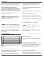
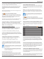
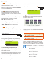
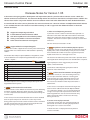
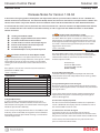
Solution 64 Intrusion Control Panel Release Notes March, 2007 Release Notes for Version 1.50.00 In the interest of ongoing product development and improvement, Bosch is proud to release software version 1 .50 for the Solution 64 Security Control Panel. This document briefly outlines the new features and improvements added in this release. Please read in conjunction with the current installation manual and other addendums for more detailed information. To coincide with this release, we are pleased to also announce that Version 1.07 of our Solution Link Upload/Download software is now available. Version 1.07 includes increased functionality, as well as support for the additional features in the V1.50 Solution 64 release. Support for up to 128 User PIN Codes Support for up to 128 Token Users Support for up to 128 RF Keyfob Users Support for Multi-Tenant Applications 1) NEW Users Increased to 128. Version 1.50 includes support for up to 128 users. Each user can have a unique PIN number, Token and RF Keyfob if required. Version 1.50 is supplied in all panels produced after March 2007. It is not possible to upgrade panels manufactured earlier than this date to 128 user capacity due to hardware differences. The manufacture date can be found on the product identification sticker located on the main PCB. 2) NEW Multi - Tenant Mode Added. Version 1.50 includes additional support for multi-tennant applications such as self storage garages or school storage lockers etc. When enabled, the new option Multi Tenant Mode option in MENU 7-7-4 will lock the first 48 users on the system to the first 48 zones on the system. Each time the user enters their PIN the corresponding zone is automtically bypassed allowing them to access the zone (area). Users 49 to 128 continue to operate as normal users. System > Installer Options > Installer Options MENU 1-6-3 1 Report / Log Entry / Exit Installer Menu 2 Report / Log Program Data Changed Y 3 Arm Only Installer PIN N 4 Zero Exit Time N 5 Auto Exit Installer Menu In 2 Hours Y 6 Auto Exit Service Mode In 2 Hours Y 7 Multi-tennant Mode N 8 Factory Defaulting Allowed Y Security Systems N i Note A number of additional options and features in the V1.50 release were originally released in V1.10. To find out more, please take the time to also read the release notes for V1.10. Solution 64 i Note The following options are included in this release however their functionality has been disabled as they are for future use. Please ignore the following options in this release. MENU 5-5 , MY Alarm MENU 5-0-3 , Check Web Email MENU 5-0-4 , Email System Log MENU 5-0-8 , Register Customer MENU 5-0-9 , Register Installer MENU 5-3-8 , User RAS PIN 2 © 2007 Bosch security Systems www.boschsecuritysystems.com BLCC110 N1.50 Issue: FTR1.5 3/07 Release Notes Solution 64 Solution 64 Intrusion Control Panel Release Notes March, 2007 Release Notes for Version 1.10.00 In the interest of ongoing product development and improvement, Bosch is proud to release software version 1 .10 for the Solution 64 Security Control Panel. This document briefly outlines the new features and improvements added in this release. Please read in conjunction with the current installation manual and other addendums for more detailed information. To coincide with this release, we are pleased to also announce that Version 1.07 of our Solution Link Upload/Download software is now available. Version 1.07 includes increased functionality, as well as support for the additional features in the V1.10 Solution 64 release. Support for up to 3 x CM104 Zone Expanders Support for up to 3 x CM110 Output Expanders Support for up to 3 x CM120 LAN Power Supplies Full Area and Output Control via DTMF Support for up to 6 x PR100 Proximity Readers 1) NEW Support For 3 x CM104 Zone Expander Modules. Version 1.10 includes support for up to three CM104 - 8/16 Zone Expansion modules. This allows zones to be located in four separate locations or buildings using individual modules which are then wired back to the control panel via the 4 wire LAN. All zones follow the global EOL setting in MENU 3-4-0 regardless of which module they are on. i.e. If Split EOL is selected, then all zones will be configured for Split EOL. Zone numbering is automatically assigned by the panel during power up depending on the module configuration found. For example if Split EOL is selected and 3 x CM104 Zone Expanders are fitted, then Zones 1 - 16 will be located on the main panel, Zones 17 - 32 will be located on CM104 Expander 1 and Zones 33 - 48 will be located on CM104 Expander 2. ZONE CONFIGUR ATION TABLE Single Alarm + Split Device Type EOL Tamper EOL Solution 64 Panel 8 8 16 CM104 Expander 1 8 8 16 CM104 Expander 2 8 8 16 CM104 Expander 3 8 8 16 Total Zones 32 32 64 Solution 64 Panel 8 8 16 CM105 Expander 16 16 32 CM106 Expander 1 8 8 16 CM106 Expander 2 8 8 N/A Total Zones 40 40 64 Added End Of Exit Beep when Part Arming Added Option to Arm All User Areas Via Prox Added Option to Expire PIN on a per User Basis Added Zone Trigger Delay Option Added Support For Remote Keypad Simulator If an RF zone is assigned to a zone which has a physical hardwired input then the RF zone will take precedence and the hardwired zone input will be disabled. i Note At this time the panel supports either CM104 zone expanders OR CM105 zone expanders however is not possible to mix both types on the one system. See the zone configuration table for the various zone configuration options available. RF zones are available regardless of which hardwired zone options are used. 2) NEW Support For 3 x CM110 Output Expander Modules. Version 1.10 includes support for up to three CM110 - 4 Way Relay Output Expanders. This feature takes the maximum output capacity of the panel to 16 high current outputs. Outputs can be located in up to four different locations or buildings using individual modules which are then wired back to the control panel via the 4 wire LAN. RF Zones This additional module support also provides for up to 6 external access control doors via the dual proximity reader inputs located on the CM110 Expanders. Any number up to a maximum of 64 zones The CM110 inputs currently support the PR100 External Proximity readers which are compatible with the Proximity Keypads. The total number of access control doors now increases to 14. 64 If a mixture of hardwired and RF zones are being used, then it is recommended that you assign the RF zones to zone numbers above the maximum number of hardwired zones. In the above example you would assign the first RF zone to Zone 49 which would leave all 48 hardwired zone inputs free. Security Systems ACCESS DOOR T YPE / C APACIT Y Firmware Internal External Total V1.05.01 or lower 8 2 10 V1.10.00 or higher 8 6 14 Output and Proximity Reader numbering is automatically assigned by the panel during power up depending on the module configuration found. Solution 64 For example if 2 x CM110 Output Expanders are fitted then Outputs 1 - 4 will be located on the main panel, Outputs 5 - 8 will be located on CM110 Expander 1 and Outputs 9 - 12 will be located on CM110 Expander 2. OUTPUT AND PROX READER MAPPING Device Type O utput Number Reader Numbe r Solution 64 Panel 1 -4 N/A CM110 Expander 1 5-8 9 -10 CM110 Expander 2 9 - 12 11 - 12 CM110 Expander 3 13 - 16 13 - 14 Proximity Readers 1 - 8 are reserved for Keypad Readers. External readers are addressed as readers 9 to 14. 3) NEW Support For 3 x CM120 Power Supply Modules. Version 1.10 includes support for up to three CM120 - 1 Amp LAN Power Supply Modules. CM120 modules can be located in up to three different locations or buildings to provide LAN voltage regeneration as well as supplying power to other modules, Intrusion Sensors, Door Strikes etc. The CM120 modules are designed to run off a standard plug pack transformer and include built in battery chargers suitable for charging 12V 7Ah batteries. As with all LAN modules, the status of the CM120 is constantly being monitored and reported to the control panel via the system LAN. MODULE CONFIGUR ATION INFORMATION i Note Multiple module support requires that each module is set to a unique address. For example if a system has 1 x CM104 and 1 x CM120 installed, they should both be addressed as ‘module 1’. If an extra CM104 was fitted then it should be addressed as ‘module 2’. The panel will only look for new devices follwing a power cycle and only if the LAN is not secured. To add new devices, make sure the LAN is unsecured before powering the system down. Set the module Address DIP switches accordingly and complete wiring as per instuctions. Once complete re-power the system. To interrogate devices connected to the LAN you can use LAN Status command, MENU-6-0-0 L AN MODULE ADDRESSING Module Nº SW 1 SW 2 SW 3 1 OFF OFF OFF 2 ON OFF OFF 3 OFF ON OFF Each different module type should be addressed starting at address 1. 4) NEW Support For Keypad Simulator Added Version 1.10 includes support for the real time keypad simulator. The keypad simulator is a new feature which can be accessed via the latest version of our Solution Link RAS software. 2 When connected to the panel using either dial up or direct connection modes, the keypad simulator option will be available via the Solution Link tool bar. The keypad simulator allows you to view any keypad on the system as well as perform any available keypad functions via the PC. 5) Output Polarities With Pre Delay. In earlier versions, outputs programmed with output polarity “Low With Pre Delay “ and “Open With Pre Delay” did not function correctly. The output would operate after the pre delay time expired however the output would then reset rather than remain latched on. This operation has been corrected in this release. 6) Battery Test On Arming Option. In earlier versions, the system would always perform a battery test on arming regardless of whether or not the “Battery Test On Arming Option” was selected. This operation has been corrected in this release. See MENU 7-3-1. 7) Outputs Programmed To Follow Chime Zones. In earlier versions, an output configured to operate when a chime zone was triggered would not reset if the chime function was turned off for that area while a chime alarm was in effect. This operation has been corrected in this release. See Output Event Type 30 - Chime Zone Triggered 8) Outputs Programmed To Follow Auto Arm Pre-Alert. In earlier versions, an output configured to operate when an Auto Arming Pre Alert timer was running would not reset if the Auto Arm Time was delayed buy a user. This operation has been corrected in this release. See Output Event Type 31 - Auto Arm Pre Alert 9) NEW Panel DTMF Control Functions Enhanced. In earlier versions, DTMF control functions were restricted to remote arming of the entire system only. Version 1.10 now includes comprehensive DTMF control of individual areas and outputs with full user PIN and TIMER GROUP access verification. Comms > Remote Access > DTMF Options MENU 5-3-5 1 DTMF Arming Y 2 DTMF Disarming N 3 DTMF User Functions N 4 DTMF Quick Arming Y 5 Reserved N 6 Reserved N 7 Reserved N 8 Reserved N Bosch Security Systems | 3/07 | FTR1.4 Solution 64 Unlike other systems, no additional hardware or modules are required for DTMF control. To configure the desired functions see MENU 5-3-5 DTMF Options. See below for DTMF control operating instructions. 1. Once the panel answers the incoming call, if either option 1, 2, 3 or 4 in MENU 5-3-5 is enabled, then the panel will play a short welcome jingle. You now have approximately 5 seconds to enter a valid PIN and log onto the panel. 2. Enter PIN followed by the # key. If the PIN is valid the system will respond with two short beeps. If the PIN is invalid then a single long beep will be heard. If a valid PIN is not entered in time, the panel will attempt to establish a modem connection as if connecting to the Solution Link software. If this happens you will need to hang up for approximately 60 seconds before trying again. 3. Once validated, the following commands can be performed. See the table below. If no keys are pressed for 20 seconds then the panel will play the exit jingle before terminating the session and hanging up. Pressing ## at any time while connected will cause the panel to terminate the session. DTMF CONTROL FUNC TIONS Operation Command Response Quick Arm All Areas 0+# 2 x Beeps Log In OK USER PIN + # Welcome Jingle Log In Failed USER PIN + # Long Beep Turn Area ON 1 + (Area Nº1-8) + 1 + # 2 x Beeps (Low - High) Turn Area OFF 1 + (Area Nº1-8) + 2 + # Turn Output ON 2 + (Output Nº1-16) + 1 + # Turn Output OFF 2 + (Output Nº1-16) + 2 + # (High - Low) End Session #+# Exit Jingle 2 x Beeps (High - Low) 2 x Beeps (Low - High) 2 x Beeps DTMF EXAMPLES Each example below shows the log on step for clarity. In practise is only necessary to log on once per DTMF control session. To turn Area 1 ON enter the following 2 + 5 + 8 + 0 + # = Log ON 1 + 1 + 1 + # = Arm Area 1 To turn Output 10 ON enter the following 2 + 5 + 8 + 0 + # = Log ON 2 + 10 + 1 + # = Turn Output 10 ON Bosch Security Systems | 3/07 | FTR1.4 To turn Output 12 OFF enter the following 2 + 5 + 8 + 0 + # = Log ON 2 + 12 + 2 + # = Turn Output 12 OFF i Note If the DTMF Quick Arm option is enabled then it is possible to remotely arm all areas without logging onto the panel. Simply enter 0 + # following the welcome jingle. Make sure that the phone being used to remotely control the panel is set to transmit DTMF tones when keys are pressed during the call. This option is disabled by default on some phones. 10) Send Test Report Menu Changed. In earlier versions, a Guest User or a Non Master Code User could initiate a test report transmission via the hold down function on the keypad yet they had no access to this option via the menu tree. (See MENU 5-9-0) V1.10 now allows Guest / Non Master Users to access this menu. 11) Random A.C. Reports Option Corrected. In earlier versions, the option to randomise A.C. Fail reports (MENU 7-3-0) when selected would only randomise across a 120 second time window instead of a 2 hour time window. This has been corrected in this release. This option can be used to minimise the incoming traffic to the control room in the event that power is lost to large parts of a suburb due to catastrophic equipment failure, storm damage etc. 12) Delay Zone Reports Option Corrected. Each zone can be individually programmed for delay reporting in MENU 3-1-7. When enabled, the zone reports will be delayed by the time period set in MENU 5-4-6. This option can be set to allow a user to enter their PIN and disable the alarm report in case they have caused a false alarm. In earlier versions, the Delay Zone Reporting Option ignored the delay time and reported the event immediately. This has been corrected in this release. 13) Alarm Memory For Keypad Generated Alarms Added. In earlier versions, when a keypad generated alarm such as a keypad fire, keypad medical or keypad panic alarm was triggered, the keypad would only display the alarm event on the keypad while the sirens were running. In this release, the system will display alarm memory for all keypad generated alarms. 14) Alarm Memory For Telco Line Fail Alarms Added. MENU 5-2-2 includes an option for the panel to generate an alarm should a Telco Line Failure occur. This option is enabled by default and will only trigger the alarm event if the panel is in the armed state. 3 Solution 64 In earlier versions, a Telco Alarm Fail would generate the alarm as programmed however no alarm memory would be displayed on the keypad once the sirens timed out. In this release, the system will display alarm memory for Telco Line Fail alarms. 15) Bypass Reports For Non Burglary Zone Types. In earlier versions, the Report Bypass option in MENU 3-1-7 for Non Burglary Zones like Keyswitch, Display Only and 24hr Non Burglary was being ignored and no bypass / un-bypass reports would be sent to the control room for these zone types. In this release all zone types will follow the Report Bypass option programmed in MENU 3-1-7. 19) Output Timing Parameter Corrected. In earlier versions, outputs which were configured to run or operate for longer than 1 hour would fail to run for the programmed time period. V1.10 includes a correction to the timer function which now allows outputs to run for the programmed time period regardless of length. 20) Menu Text Changes And User Interface Improvements. The following changes have been made to improve clarity for all users. 1. MENU 6-2-5 now reads “View RF Device ID”. 2. MENU 1-4-2 ,option 6 now reads “Always Report Op/Cl”. 16) NEW End Of Exit Beep In Part Mode Added. In earlier versions, arming in Part Mode 1 or 2 would start the exit timer and count down display however unlike “All On” arming there was no audible indication. 3. MENU 7-7-0 ,option 5 now reads “Cannot Change Own Pin” . 4. The phrase “ALLON” in some menus has changed to “ALL ON”. This release now includes an “End Of Exit” beep indication which will sound when the exit timer expires. To disable this function remove the exit warning option in MENU 6-1-5 Beeper Options. 17) NEW Force Alarm On Zone Tamper Option Added. In previous versions, if the area was in the disarmed state and a zone tamper alarms was triggered, the system would report the tamper alarm to the control room and display on the keypad but would not trigger the sirens unless the area was armed. Inputs > Global Input Options > MENU 3-4-2 1 Tamper On Short N 2 Reserved N 3 Response Time 500ms N 4 Reserved N 5 Keyswitch Open/Close Y 6 Alarm On Tamper N 7 Reserved N 8 Reserved N i Note This option only takes effect when the EOL value has been set to Alarm + Tamper monitoring in MENU 3-4-0, Option 11, 12 or 14, or for RF device tampers. 18) Sequential Handover And Bypassed Zones. In previous versions, if the sequential handover option has been selected in MENU 2-1-2 and a zone which is in the entry path has been bypassed, the system would generate an alarm because the entry sequence was not sequential. To prevent this scenario from occurring Version 1.10 now excludes bypassed zones from the sequential handover list. 4 21) NEW SMS Reporting To Pager Networks. A new transmission format has been added in this release to cater for SMS reporting to pager networks which do not implement parity such as Link Paging. See Transmission Type 14 - “SMS NO PARITY”. You should verify the required protocol for your pager company before implementing this option. Version 1.10 includes a new Alarm On Tamper input option which when set will force the sirens to trigger regardless of whether or not the area is armed. See MENU 3-4-2 Option 6 “Alarm On Tamper”. Input Options 5. When an output went into a trouble condition, the keypad would display a System Trouble Alert Box and an Output Trouble Alert Box. This release no longer displays the System Trouble Alert Box for faulted outputs as it served no purpose. 22) Area Senior Watch Alarm Reports. (Dead man Alarm) In earlier versions, if Senior Watch in MENU 2-1-2 was enabled for an area and the Senior Watch Time Period in MENU 7-2-6 was set to 0 (zero) the system could generate spurious dead man reports to the control room. This has been corrected in this release so that Senior Watch alarms will only be generated if the time period is set greater than 0 (zero). 23) Alarm On Exit Error Reporting Corrected. In earlier versions, no report was sent when an “Alarm On Exit Error” occured if the transmission format was set to Contact ID. SIA and other transmission formats where not effected. This has been corrected in V1.10 and the system now reports CID event 374 when an Alarm On Exit Error occurs. 24) User Duress Reports in SIA Format Corrected. In earlier versions “User Duress” reports were not being sent if the transmission type was set to SIA format. This has been corrected in V1.10 and the system now reports “User Duress” alarms when SIA transmission format is selected. Bosch Security Systems | 3/07 | FTR1.4 Solution 64 25) Output Polarity “One Shot + Retrigger Corrected. In earlier versions, outputs programmed with a polarity type of “One Shot + Retrigger” did not operate correctly. The output failed to reset the one shot timer when the event retriggered which meant that output would operate at the specified one shot time rather than being reset for each retrigger. This has been corrected in V1.10 so that each retrigger causes the one shot timer to reset. 26) NEW Zone Trigger Delay Option Added. Version 1.10 includes a new Zone Trigger Delay option which can be used to delay or hold off the alarm for a period of time. This function can be used when monitoring pump alarms, temperature alarm and freezer alarms. This has been corrected in V1.10 release. 28) User PIN Expire Option Enhanced. In earlier versions, the user expire option used a common timer for all users which was not practical. The V1.10 release includes a new option which allows you to set any user’s pin to expire at specific time. MENU 1-4-6 is used to set the “Expire Date” for each user. To activate the user expire function you also need to set the User Expire option in MENU 1-4-2 User Options, PIN Expires for each user. i Note The user expire date in MENU 1-4-6 can be changed by master code user allowing them to extend or shorten the expire time if required. This option can also be used to create a “Door Open To Long” input when implementing access control functionality. 29) NEW Arm All User Areas Via Prox Reader. In earlier versions, it was not possible to set a prox reader to Arm / Disarm all areas which a user belongs to with one presentation of their token. The zone delay option is selected under the pulse count option in MENU 3-1-3. Option 13, 14 and 15 allow you to select the pulse delay in scale. Options are Seconds, Minutes or Hours. Once the scale is set you can then set the multiplier value under MENU 3-1-4. See examples below. Version 1.10 includes a new reader option in MENU 1-6-3 Option 8 called “All User Areas”. When set the option will cause the system to arm / disarm all areas which the token holder belongs to on a single token presentation. This option can be set per reader. ZO NE DEL AY TRIGGER EXAMPLES Configure Zone 3 with Delay of 3 minutes (180 seconds). 1. Program zone type etc as per normal. Then set Zone 3 to Pulse delay scale SECONDS in MENU 3-1-3, option 13. 2. Set the zone 3 delay multiplier in MENU 3-1-4 to 180. 3. If zone 3 is triggered and it remains open for 180 seconds, then an alarm event will be triggered. If the zone re-seals within the 180 second period then the counter will reset and no alarm will be triggered. Configure Zone 10 with Delay of 1 hour (60 minutes). 1. Program zone type etc as per normal. Then set Zone 3 to Pulse delay scale HOURS in MENU 3-1-3, option 15. 2. Set the zone 3 delay multiplier in MENU 3-1-4 to 1. 3. If zone 3 is triggered and it remains open for 1 hour, then an alarm event will be triggered. If the zone re-seals within the 1 hour period, the counter will reset and no alarm will be triggered. i Note The trigger delay multiplier in MENU 3-1-4 will always display the number and the word seconds. This is because this this option has a dual function. When setting zone delay you should ignore the word seconds and simply multiply the number by the scale option selected to calculate the actual delay time. 27) Alarm On Output Device Fail. In earlier versions, if the Alarm on Device Fail option in MENU 4-1-5 was set and the system was disarmed when the device failure occured the system would send the report to the control room but would not trigger the sirens. Bosch Security Systems | 3/07 | FTR1.4 Access > Prox Reader > Reader Options MENU 1-6-3 1 All On Arming Allowed 2 Disarming Allowed Y 3 Enable Badging N 4 Zero Exit Time N 5 Part On Arming Allowed N 6 Arm If Single Area User N 7 Reserved N 8 All User Areas N Y 30) Roaming Keypad Prox Reader Operation Changed. In earlier versions, if a multi-area user presented their token to a roaming keypad reader, the system would disarm the first area which they belonged to and keep them logged on to the system. In Version 1.10 the operation has been changed so that multiarea users will only be logged on when presenting their token to a roaming keypad reader. Once logged on the user can hold down the “All On” or “All Off” keys to arm / disarm all areas they belong to or use the arrow keys to navigate to a specific area and then press the On/ Off key as required. 31) RAS Disconnect On Alarm Operation Changed. In earlier versions, if MENU 5-3-4 option 3, “Abort RAS on Alarm” was enabled the panel would terminate the RAS programming session regardless of whether or not the session was a remote or a direct connection. In Version 1.10 this option has been changed and will now only terminate the programming session if it is a remote connection. A direct connection will remain connected. 5 Solution 64 32) NEW User RAS Security PIN Option Added. A new option has been added in this release to allow for an independant User connection to the panel using our Solution Link End User programming software. MENU 5-3-8, User RAS PIN option is defaulted to 00000000 and is currently reserved for future use. In Version 1.10 the default event assigment for all outputs has been changed to 0. Outputs > Properties > Event Assignment MENU 4-1-2 0 0 0 Event Assignment Op001 33) NEW Telephone Ring Count Analysis Changed. The way ring counting is analysed for the Australian ring tone has been changed in V1.10 to make it easy for new users to learn and simpler to use when establishing a remote connection. 000 Press 0-9 OK to SAVE 36) NEW Keypad Emergency Alarm Trigger’s. Version 1.10 introduces a new method for triggering keypad Fire, Medical and Panic alarms. In earlier versions, the panel would count rings as follows, RING .. RING ......... RING .. RING would be counted as 1 ring. In V1.10 the panel will now count rings as follows, RING .. RING will be counted as 1 ring. Occasionally you will hear half a ring at the moment the line is switched through to the premises. In this case the panel will count the rings as follows, .. RING.........RING .. RING would be counted as 1 ring. 34) NEW Ring Count Default Changed. To allow for the changes in the ring count analysis in V1.10 the default ring count has been changed from 10 rings to 20 rings. The maximum number of rings which can be programmed has also been increased from 15 to 30 rings. NE W KEYPAD EMERGENC Y AL ARM TRIGGER ’S Comms > Remote Access > Ring Count The new methods are easier for the end user to remember and also allow for labelling to be applied to the keypad further simplifying operation. At this time both old and new methods function. 0 = No Answer MENU 5-3-3 20 1 to 30 = Answer Ring Count This menu sets the number of rings the panel will wait until answering an incoming call. Programming a zero will stop the panel from answering any incoming calls. Ring Count P001 20-20 Rings Press 0-9 OK to SAVE 35) Output Event Assignment Default Changed. The output event assignment option allows you to assign or map an Output event to an Area number (1 to 8), a User number (1 to 128), a Zone number (1 to 64) or a Group number (1 to 8) that the output will follow. Key Sequence Ë+Ê Ê+È È+Â Event Triggered Hold for 2 seconds Keypad Fire Alarm Hold for 2 seconds Keypad Panic Alarm Hold for 2 seconds Keypad Medical Alarm 37) D Type Receiver Re-named Bosch Serial Receiver. In Version 1.10 , Option 4 in MENU 3-5-0 has been re-named from D Type Serial Rcvr to Bosch Serial Receiver. Both RF3212 and RF3212E receivers from Bosch are supported by this option. i Note The following options are included in this release however their functionality has been disabled as they are for future use. Please ignore the following options in this release. MENU 5-5 , MY Alarm MENU 5-0-3 , Check Web Email MENU 5-0-4 , Email System Log Programming a zero will assign the output event to follow all areas, users, zones or access groups depending on the event type. Refer to Output Event Type Table in the Installation manual for a complete listing of available options. MENU 5-0-8 , Register Customer MENU 5-0-9 , Register Installer MENU 5-3-8 , User RAS PIN 6 © 2007 Bosch security Systems www.boschsecuritysystems.com BLCC110 N1.10 Issue: FTR1.4 3/07 Release Notes Solution 64 Intrusion Control Panel Release Notes Solution 64 July, 2006 Release Notes for Version 1.05.01 In the interest of ongoing product development and improvement, Bosch is proud to release software version 1.05.01 for the Solution 64 Intrusion Control Panel. This document briefly outlines the improvements added in this release. Please read in conjunction with the current installation manual and other addendums for more detailed information. 1) Zone Status Indicator (Green LED) Function Corrected. Normally the Green Status indicator LED on the keypad will flash to indicate that a zone or zones are unsealled and would remain on steady when all zones are sealled. If however the zone is an RF Zone which has been programmed for pulse count and the zone remains open for longer than 10 seconds then the status indicator will continue to flash even if the zone reseals. This issue is only relevant if the Zone is an RF Zone and it has been programmed for pulse count. This has been corrected in V1.05.01 2) RF Zone Pulse Count Function Corrected. In previous versions any RF Zone programmed for pulse count which was left unsealled when the area was armed would cause an alarm to occur the next time the devices supervision signal was received by the panel (approximatly 10 minutes after arming). This has been corrected in V1.05.01 Solution 64 i Note The following options are included in this release however their functionality has been disabled as they are for future use. Please ignore the following options in this release. MENU 55 - MY Alarm MENU 503 - Check Web Email MENU 504 - Email System Log MENU 508 -Register Customer MENU 509 -Register Installer 2 © 2006 Bosch Security Systems www.boschsecuritysystems.com BLCC110N1.05.01 Issue: FTR1.3 Release Notes 7/06 Solution 64 Intrusion Control Panel Solution 64 Release Notes April, 2006 Release Notes for Version 1.05 In the interest of ongoing product development and improvement, Bosch is proud to release software version 1.05 for the Solution 64 Intrusion Control Panel. This document briefly outlines the numerous new features and improvements added in this release. Please read in conjunction with the current installation manual and other addendums for more detailed information. To coincide with this release, we are pleased to also announce that Version 1.03 of our Solution Link Upload/Download software is now available. Version 1.03 includes increased functionality, as well as support for the additional features in the V1.05 Solution 64 release. 3) Telco Line Fail Reporting Corrected. In previous versions a telco line fail would be reported as a Contact ID event E351 with C001 instead of E351 with C891, where C891 represents panel number 1 in the base station template . The telco line restore reports correctly as event R351 with C891. Support for Tamper Keypads added Installer Default Lockout Indication added User ID for Keyfob Panic and Low battery added Arming in Part Mode 1 and 2 Via Prox Readers Token Control Via Common Area Keypads This has now been corrected in V1.05. 1) NEW Support Added For Tampered Keypads. Version 1.05 includes support for the recently released tampered keypads which are available with or without built in proximity readers. The “Enable Rear Tamper” option (MENU 6-1-4, Option 4) needs to be enabled for each tampered keypad fitted to the system. Devices > Keypads > General Options MENU 6-1-4 1 Keypad Extinguish N 2 Greeting On Arm Y 3 Greeting On Disarm Y 4 Enable Rear Tamper N 5 PIN To Change Area N 6 Home Area Only N 7 Report Keypad Temperature Y 8 Display Area Indicators N The above options can be configured independantly for each keypad fitted to the system. 2) NEW Panel Default Lockout Indication. In earlier versions it was difficuilt to determine if panel defaulting had been disabled. When this option has been set via MENU 7-7-4, it is impossible to default the system without knowing the installer code. In this release, if the installer default function has been disabled then the panel will pulse or click the line seize relay 4 times during power up. If this occurs and the installer code is unknown you will need to return the panel to the place of purchase for defaulting. Charges may apply for this service. 4) NEW Keyfob Panic And Low Battery Reports By User In previous versions it was not possible to indiviually report RF keyfob panic alarms or low battery events per user. in V1.05, zones number 301 to 428 have been assigned to represent keyfob events for users 1 through to user 128. This feature now allows the panel to be used in portable duress alarm applications where positive user identification is required. Eg. A keyfob panic alarm triggered by user 26 will report as E120-GG-Zn326. See the Base Station Reporting template V1.04 or higher for more information. 5) NEW Token Control Via Common Area Keypads. In previous versions, if a user who belonged to only one area presented their token to a roaming prox keypad reader, the system would log them on and move the keypad to display the users area. To arm the area the user would need to swipe their token a second time. In this release a new option called “Arm If Single Area User” has been added to the Reader Options MENU 1-6-3. When this option is set, a user who belongs to a single area only needs to present their token once to the keypad for the area to arm. This function only works via keypad readers and for users who only belong to one area. 6) Screen Saver Display Corrected. In previous versions the area armed, disarmed and part armed icons where not being displayed when the keypad was in screen saver mode. In V1.05 the icons are displayed correctly when in screen saver mode. Solution 64 7) NEW Arming In Part Mode Via Prox Readers. In previous versions it was not possible to configure a reader to only allow arming in Part mode as the reader still required the “Arming Allowed” option to be enabled. In this release the arm in part mode via prox reader feature has been improved and it is now possible to configure a reader to only allow arming and disarming from part mode. To configure the reader for part arming only, select option 5 , “Part On Arming Allowed” and deselect option 1, “All On Arming Allowed” in the Reader Options MENU 1-6-3. Once enabled, swiping the token once will arm the area in part mode 1. If part mode 2 zones have been programmed, swipe the token a second time within 5 seconds and the area will arm in part mode 2. See below for text changes and additional options in the Reader Options Menu. Access > Prox Reader > Reader Options MENU 1-6-3 1 All On Arming Allowed Y 2 Disarming Allowed Y 3 Enable Badging N 4 Zero Exit Time N 5 Part On Arming Allowed N 6 Arm If Single Area User N 7 Reserved N 8 Reserved N The above options can be configured independantly for each prox reader or prox keypad fitted to the system. i Note The following options are included in this release however their functionality has been disabled as they are for future use. Please ignore the following options in this release. MENU 55 - MY Alarm MENU 503 - Check Web Email MENU 504 - Email System Log MENU 508 -Register Customer MENU 509 -Register Installer 2 © 2006 Bosch Security Systems www.boschsecuritysystems.com BLCC110N1.05 Issue: FTR1.2 Release Notes 4/06 Solution 64 Intrusion Control Panel Solution 64 Release Notes February, 2006 Release Notes for Version 1.04.04 In the interest of ongoing product development and improvement, Bosch is proud to release software version 1.04.04 for the Solution 64 Intrusion Control Panel. This document briefly outlines the numerous new features and improvements added in this release. Please read in conjunction with the current installation manual and other addendums for more detailed information. To coincide with this release, we are pleased to also announce that Version 1.03 of our Solution Link Upload/Download software is now available. Version 1.03 includes increased functionality, as well as support for the additional features in the V1.04.04 Solution 64 release. 3) NEW Latching Chime Zone Option Added. It is now possible to select Chime mode to latching on a per area basis. When this option is selected, if a chime zone is triggered then any outputs programmed for chime alarm and or the keypads sounder will trigger and remain on until a valid user code is entered. The keypad will display the zone which triggered the chime alarm. Latching Chime Mode added Tone Bypass support for RAS Connection added Automatic Smoke Detector Reset added Installer Code can now be restricted per Keypad Various Panel Defaults Have been Improved Fire Zone Testing Improved AutoArm Multiple areas by Schedule Improved Areas > Commands > Chime Mode 1) NEW Automatic Smoke Sensor Reset Option Added. Version 1.04.04 includes a new option which when set, will trigger any output that is programmed as event type 49 - Smoke Sensor GND to operate on the next arming cycle, therefore resetting the connected smoke sensors each time the area is armed. If this option is not set then a manual reset will need to be performed via MENU 3-0-5. Areas > Properties > Input Options MENU 2-1-2 1 Non Sequential Handover (Entry Path) 2 Pulse Count Handover Allowed Y 3 Senior Watch N 4 Reset Smoke on Arming Y 5 Reserved N 6 Reserved N 7 Reserved N 8 Reserved N Y MENU 2-0-6 The Chime Mode option allows you to program how chime zones will operate on an area by area basis. In latching mode a valid PIN will need to be entered to reset the chime alarm. Available options include; Chime Always Chime For 000 Seconds Chime After 000 Seconds Chime Latching 4) Swipe Token Text Changed In Version 1.04.04, the keypad now prompts with the words “Present Token” instead of “Swipe Token” when learning a Token or Card into the panel. 5) Keypad Back light Function Changed On previous releases, the keypad back light would occasionally not switch to full brightness when a user token was presented to the keypad reader. In this release the panel will send an awaken command to all keypads when the system is armed forcing the back light to return to full brightness. 2) Keypad Quarantine In earlier versions, if the keypad lockout time was set to 000 seconds and the maximum number of code retries was exceeded, then the keypad siren would sound and the keypad would be quarantined indefinitely. 6) Zone Status Display Improved The zone status command, MENU 3-0-0 has been improved in version 1.04.04 and now displays the zone condition as well as the measured EOL resistance value. In this release, if the keypad lockout time is set to 000, and the code retry count is exceeded, the keypad siren will sound but the keypad will not be quarantined. Entering a valid code will reset the keypad siren. 7) Call Diversion Function Changed In previous versions, if a call diversion string has been programmed, the panel would activate the call diversion when the panel was armed in either the Part On mode or All On mode. In this version, the call diversion will only activate when the panel is armed in the All On mode. Solution 64 8) NEW Restrict Installer Access Per Keypad Option Added. In installations with multiple keypads, you may want to restrict the installer code access to one or a limited number of keypads. For example you may want to restrict installer access to only the keypad which is located in the communication room. To configure this option, select “Installer PIN Not Allowed” option for each required Keypad. See MENU 6-1-5, Option 7 below. 9) NEW Prevent PIN Arm/Disarm Per Keypad Option Added. Situations may arise where a keypad is required for access door control only. In this situation to prevent Arm/ Disarm control, set the “PIN Arming Not Allowed” option for each desired keypad . This has been corrected in this release and the system now sends a close report when all areas are armed, and an open report when the first area is disarmed. System > System Options > Area Options MENU 7-7-1 1 Area 1 = Common Area N 2 First To Open Last To Close N 3 Reset Siren All Users ( All Areas) Y 4 Power Up In Same State As Powered Down Y 5 Fault Acknowledge All Areas Y 6 Delay Trouble Beeps Y 7 Reserved N 8 Reserved N Valid user codes with the appropriate access level can still be used to operate the door strike from the keypad when this option is set. (*** System Wide Parameter ***) See MENU 6-1-5, Option 6 below. 13) NEW Panel Default Changes A number of system defaults have been changed to better reflect the most commonly chosen options. See below. Devices > Keypads > Beeper Options MENU 6-1-5 Trouble Alerts Y 2 Entry Warning Y 3 Exit Warning Y 4 Chime Tone Y Device > RF Devices > 5 Display Temperature N 6 N RF Device Options PIN Arming Not Allowed 7 Installer PIN Not Allowed N 8 Show Alarm When Armed N The above options can be configured independently for each keypad fitted to the system. 10) Manual Output Control with Inverted Polarity In earlier versions, the keypad text prompts did not reflect the correct output polarity for outputs which are configured to be on in the normal state. For example Output 3 is defaulted to polarity type Low One Shot Open, which means that in the normal state the output is on. In version 1.04.04 the text prompts now correctly follow the output polarity selected for each output. 11) NEW Zone Testing When Arming When arming, the panel will notify the user about any zones which are currently unsealed. At this point the user can abort the arming process and seal the offending zone, or they can force arm (if allowed) leaving the zone open in which case a trouble will be reported. In version 1.04.04, if the force arm prompt appears when arming, the user can press the ON key again, and the system will re-scan the zones. Any previously open zones that have re-sealed will not trigger the force arm prompt after the re scan. 12) First To Open Last To Close Option Corrected The first to open last to close option, (MENU 7-7-1) did not function correctly in previous versions. a) MENU 6-6-2 Open Zone On Lost RF This option has been defaulted to NO because when and RF Zone fails it’s supervision check, a report is automatically sent to the control room. 1 MENU 6-2-2 1 Display RF Tamper Y 2 Report RF Tamper Y 3 Report RF Low Battery Y 4 Report Lost RF Device Y 5 Open Zone On Lost RF N 6 Audible Keyfob Panic Y 7 Report Keyfob Panic Y 8 Keyfob Function 1 Key = Part On Y b) MENU 5-2-2 Alarm On Line Fail If Armed This option has been defaulted to YES because more often than not, if an intruder cuts the telco line you would want the sirens to sound. Comms > Properties > Phone Line Options MENU 5-2-2 1 Display Telephone Line Fail 2 Report Telephone Line Fail Y 3 Alarm On Line Fail If Armed Y 4 Alarm On Line Fail If Disarmed N 5 Reserved N 6 Reserved N 7 Reserved N 8 Display Phone In Use N Y c) MENU 7-7-1 Delay Trouble Beeps This option has been defaulted to YES based on customer feedback. When set to YES the system will prevent trouble beeps from the keypad between 10pm and 7am. Bosch Security Systems | 2/06 | FTR1.1 Solution 64 Should the trouble event still be in effect at 7am the keypad beeper will start to sound. At all times the trouble event will be displayed on the keypad and stored into the system log. d) MENU 7-7-1 Reset Siren All Users This option has been defaulted to YES because in most cases in a partitioned system you would want all authorised users to be able to reset the sirens. System > System Options > Area Options MENU 7-7-1 This has been corrected in the 1.04.04 release and the loop function now increments through all areas on the system. Users assigned to multiple areas are not effected provided they also have access to Area 1. 15) NEW Auto Arming All Areas In earlier versions, auto arming multiple areas required multiple schedules. In version 1.04.04 it is now possible to arm all areas using just 1 schedule. To do this select the corresponding auto arm schedule and set it’s index to 000. See MENU 7-5-4. 1 Area 1 = Common Area N 2 First To Open Last To Close N System > Schedules > 3 Reset Siren All Users ( All Areas) Y Index 4 Power Up In Same State As Powered Down Y 5 Fault Acknowledge All Areas Y 6 Delay Trouble Beeps Y 7 Reserved N 8 Reserved N (*** System Wide Parameter ***) e) MENU 2-1-1 Duress Allowed This option has been defaulted to YES as there is very little chance that a user would repeat the last two digits of their code by accident when disarming. Areas > Properties > General Options MENU 2-1-1 1 Exit Time Restart N 2 Reset Alarm Memory On Disarm N 3 Duress Allowed Y 4 Acknowledge All Faults N 5 Single Button Arming - All On Y 6 Single Button Arming - Part On Y 7 Link To Common Area Y 8 Single Button Part Off N f) MENU 2-9-2 Service Interval The default Service Interval has been changed to 000 weeks. This means that from default, no service reminder will be given. If you want to take advantage of this feature you will need to program the number of weeks to wait between reminders into this location. Areas > Area Testing > User Test Interval 0 0 DAYS 14) RF Keyfob Panic Operation Corrected In previous versions, triggering an RF Keyfob panic for any user assigned to any area other than area 1, would cause the system to loop on area 1, requiring a system power cycle to recover. Bosch Security Systems | 2/06 | FTR1.1 MENU 7-5-4 0 16) Recurring System Report Linked to Swinger Dialler Count. In previous versions, a recurring system trouble event would send a new report each time the event occurred, without any swinger dialler override. In V1.04.04 System Trouble events have been linked to the swinger dialler setting in MENU 5-4-5. This means that a recurring system trouble event will only report until the swinger dialler count is reached and then it will be locked out. The event will reactivate the next time any area is armed or disarmed. System trouble events will only trigger the sirens, if applicable once per arming cycle. Comms > Dialler Reporting > Swinger Dialler MENU 5-4-5 (*** System Wide Parameter ***) 0 6 17) Display Output Status On Keypad Option Changed If the “Display Output Status On Keypad” option (MENU 4-1-5) has been selected, and the output in question is activated then a message will be displayed in the scroll bar. In previous versions, if you arm the panel while this massage is being displayed then the system will prompt you to force arm the output to complete the arming cycle. In the 1.04.04 release, output status display messages are now filtered out and the panel will not consider these messages during the arming cycle. MENU 2-9-1 0 (*** System Wide Parameter ***) 18) PIN Always Required Option and Pop Up Boxes In Version 1.04.04 , when the PIN Always Required option is selected, and a pop up message box is displayed, the system will prompt the user to Enter PIN + OK to acknowledge the message. In previous versions the system would prompt Press OK, however this would not acknowledge the message because no PIN had been entered. Solution 64 19) Turn Area On / Off Command Corrected In previous versions, the Turn Area On / Off option (MENU 2-0-1) does not filter the user to restrict them from controlling an area they don’t belong to. 23) NEW Tone Bypass Function Implemented It is often difficult to establish a remote connection to a panel if the customer picks up the phone or if a fax or answering machine answers the call before the panel does. In version 1.04.04 the panel filters the user and only provides control for areas they are assigned to. A valid PIN is required in all cases. While the ultimate solution to this problem is the use the CLI Intelliconnect method, this requires the customer to enable CLI via their telco provider. Areas > Commands > Turn Area On/Off -- MENU 2-0-1 20) Domestic Reporting and Pulse Dialling In previous versions, if both the Domestic Reporting format and pulse dialling option have been selected, the system may not dial the complete phone number if it is longer than 6 digits. This is due to the amount of time it takes to dial in pulse format compared to DTMF dialling. All other reporting formats are not effected even if pulse dialling has been selected. In version 1.04.04, the internal dial process timer has been increased to 30 seconds which provides ample time to dial the number in pulse or decadic format. 21) Walk Testing Fire Zones In previous versions, placing a short across the EOL resistor to test a fire zone would not be accepted as a valid test and the zone would remain in the untested zone list. In version 1.04.04 the walk testing function has been changed to allow a short across a fire zone EOL resistor to be accepted as a valid test. 22) RF Keyfob Panic Alarm Reporting In earlier version, panic alarms trigger via RF keyfobs would follow the status route when reporting the alarm. In domestic dialling mode, the status route would typically be disabled and this would prevent the keyfob panic for being transmitted. In version 1.04.04 the reporting route for keyfob panic alarms has been changed to the Emergency route which would not normally be disabled when using domestic dialling. © 2006 Bosch Security Systems www.boschsecuritysystems.com When enabled, the new Tone Bypass option (MENU 5-3-4) tells the panel to listen to every answered call and to look for a specific sequence of DTMF tones. The tone sequence will be sent by the remote programming software and when the panel recognises them, it will immediately seize the line away from the answering party and the programming session will commence. The feature requires Solution Link remote programming software version 1.03 or higher. Comms > Remote Access > Solution Link RAS Options MENU 5-3-4 1 RAS Allowed Y 2 Call Back Verification Required N 3 Terminate RAS on Alarm Y 4 Answer Bypass Y 5 Answer Incoming Call Only If Armed N 6 Tone Bypass Y 7 Allow User Functions Via Remote Access Software Y 8 Report / Log RAS Start / End Sessions Y i Note The following options are included in this release however their functionality has been disabled as they are for future use. Please ignore the following options in this release. MENU 55 - MY Alarm MENU 503 - Check Web Email MENU 504 - Email System Log MENU 508 -Register Customer MENU 509 -Register Installer BLCC110N1.04.04 Issue: FTR1.1 Release Notes 2/06 Solution 64 Intrusion Control Panel Solution 64 Release Notes December, 2005 Release Notes for Version 1.04 In the interest of ongoing product development and improvement, Bosch is proud to release version 1.04 of the Solution 64 Intrusion Control Panel. This document briefly outlines the numerous new features and improvements added in this release. Please read in conjunction with the current installation literature for more detailed information. CM105 Zone Expander support added CM120 Power Supply support added CM104 Zone Expander support added SIA + Text reporting format implemented Timer added for Chime Alarm RF Device ID Sniffer added Secure LAN option added Real-time Program Updating added CM195 Multi RF Receiver support 5) NEW LAN Status Command Devices > Commands > LAN Status 2) NEW Support added for Bosch - CM120 LAN Power Supply Module. This power supply can be added anywhere on the system LAN to provide up to 1Amp of additional current for powering sensors etc. Low Battery and AC Fail signals are also provided over the LAN and remotely via Solution Link. 3) NEW Support added for Bosch - CM195 Multi RF Receiver Interface Module. This module allows up to 3 identical Radio receivers to be connected to the Vision panel at the same time enabling the installer to position the receivers over a larger area to provide greater coverage. The CM195 module also allows Inovonics RF receivers and wireless devices to be interfaced to the Vision panel. 4) NEW LAN Scan Implemented Version 1.04 includes a LAN scan function which automatically scans the system LAN for connected modules and devices during power up and then adds support for them. The scan will be performed every time the panel is powered up and may take up to 45 seconds to complete. While the system is scanning, the Green status LED will flash and the Red Dialler LED will remain on steady. Keypads found to have no area assignment are scanned and flagged with “No Area” in the display. Following a factory default, all keypads will be set to home area 1. MENU 6-0-0 This menu will bring up a list of all devices connected to the system LAN. Use the up and down arrows to highlight a device then press OK and the keypad will then display all relevant information for the selected device. 6) NEW LAN Secure / Un-Secure Command Devices > Commands > LAN Secure 1) NEW Support added for the Bosch - CM104, CM105 and CM106 Hard wired Zone Expander Modules. The CM104 and CM105 can be connected anywhere on the system LAN providing additional hard wired zone inputs and accessory power for sensors. Only one expander can be fitted to the Solution 64. The CM106 can be fitted to the CM105 when the full complement of 64 hard wired zones is required. MENU 6-0-1 This menu allows you to secure the device LAN on the Vision Panel. When the LAN has been secured the system will not recognise any new devices which may be added to the LAN. It will also prevent the automatic LAN scan from being performed during power up. If you need to add a new device to the LAN you first need to un-secure the LAN, power down the system, connect the new device and re-apply power. Once all devices have been added you should re-secure the LAN. 7) NEW Support added for the following RF devices from Secure Wireless. EV-REC3-Bosch (Radio Receiver) REM-REC3 (4 Button Remote) DW-REC3 (RF Reed Switch) PIR-REC3 (RF PIR - Pet Immune 20Kgs) GB-REC3 (RF Glass Break Detector) SM-REC3 ( RF Smoke Detector) 8) NEW Auto Arming Options Entering a valid PIN + the OFF key while the Auto Arm pre-alert timer is running will display two new options. Extend Auto Arm Abort Auto Arm Use the up and down arrow keys to highlight the required function then press OK. The time extension is fixed at 1 hour. Solution 64 9) NEW Auto Arm Time Extended Report If the user extends the auto arm time, the panel will report a CID event 464 to the monitoring station. 10) NEW EOL Resistor Value Changes The following EOL resistor values have been added making it easier to change over of Tecom and Concept panels. 16) Inputs > Global Input Options > MENU 5-0-5 This command performs the same function as holding down the default switch on the Vision panel for 5 seconds. Once initiated, the panel will enter direct link mode ready to communicate with the Solution Link software. The green status LED on the panel will flash slowly indicating the function has been activated. MENU 3-4-0 0 = No EOL 5 1 = 1K0 6 = 4K7 11 = 6K8 with Tamper (2K2) 2 = 1K5 7 = 5K6 12 = 10K with Tamper (10K) 3 = 2K2 8 = 6K8 13 = 22K 4 = 2K7 9 = 8K1 14 = 3K3 with Tamper (6K8) 5 = 3K3 10 = 10K 17) NEW Real-Time Program Update During Downloads Version 1.04 includes a new function which will update EOL resistor value changes and zone state changes in real time. Changes are updated every time a download is performed during the Solution Link session. 15 = Split EOL (Parallel) (3K3 = Primary, 6K8 = Secondary) 11) NEW View Status in Part Mode This feature allows the end user to view detailed system status information while the system is armed in Part mode. Press the down arrow to obtain a status list showing any system troubles currently in effect as well as zone and output status information. 12) NEW Keypad and Keyfob Alarm Display Emergency alarms such as Keypad Fire, Medical and Panic alarms and Keyfob Panic alarms will now display in the status scroll list as well as in the drop down list. The status message will show the alarm type and keypad number which the alarm was generated from and in the case of a keyfob panic alarm the user name and number will be shown. 13) NEW PGM Input - Exit Timer Version 1.04 now forces the exit timer to run when the panel has been armed via the programmable input. For example if the input is programmed for Pulse On/Off and a trigger signal is received then the exit timer will begin and the system will not fully arm until the exit time expires. 14) NEW PGM Input to Arm All Areas New in V1.04 When the Programmable Input is configured as an on/off input, a valid trigger signal will cause all areas on the panel to arm and or disarm. If you require individual area arm / disarm control you should use a key-switch zone. Earlier versions would only arm Area 1. 2 Direct Link Request Command Start Direct Link To allow for these two options we have removed support for 12K and 15K EOL resistor values. EOL Value NEW Comms > Commands > Type 11 = 6K8 with Tamper (2K2) Type 12 = 10K with Tamper (10K) 15) NEW Strobe Pulse Time Extended The strobe pulse flash duration for On / Off indication has been extended to 5 seconds for OFF and 10 seconds for On. These times are fixed and should allow for most strobe types in the market today 18) NEW Daylight Savings Option Change Version 1.04 includes a change to the week of the month parameter used in the Summer Time on and Summer Time Off options. Week 5 has been replaced with Last week. Daylight savings time changes take effect on the last Sunday of the month in Europe. 19) NEW ”Block If All On” Output Option Version 1.04 includes a new output option called Block If All On. Outputs > Properties > Output Options MENU 4-1-5 1 Do Not Operate On Low Battery Y 2 Display Overload Y 3 Report Overload Y 4 Display Device Fail Y 5 Report Device Fail Y 6 Alarm On Device Fail N 7 Block If All On N 8 Display Status Message N Selecting this option will prevent the output from operating if the panel is armed in the all on mode. This option is particularly useful when using a radio keyfob for arm and disarm as well as garage door control. Enabling the Block If All On option on the output which is controlling the garage door will prevent the user from accidentally opening the door before they disarm the system. Bosch Security Systems | 12/05 | FTR1.1 Solution 64 1) 20) NEW Key-Switch Open Close Option Added Version 1.04 includes a new feature which allows you to select whether or not a zone programmed as a Key-switch Zone, will send opening and closing reports. The default is set to Off. A001 Security System A002 Area 2 Name A003 Area 3 Name Press OK or MENU Inputs > Global Input Options > Input Options To set the required chime mode enter [MENU] + [2] + [0] + [6] and select the area from the list then press [OK]. MENU 3-4-2 1 Tamper On Short N 2 Reserved N 3 Response Time 500ms N 4 Reserved N 5 Keyswitch Open Close N 6 Reserved N 7 Reserved N 8 Reserved N ) Use the up and down arrow keys to select the required chime mode. If the chosen type requires a time parameter use the right arrow to move to the time field and then use the up and down arrow key to select the appropriate time. When finished press [OK]. Chime Mode A001 Chime For 000 Seconds Press OK to SAVE (*** System Wide Parameter ***) 21) NEW View RF Device ID View RF I.D. MENU 6-2-5 In version 1.04, the device ID display has been improved and now also shows the device type and description within the system as well as the RFid. The information for each transmission will remain on the keypad display until either another transmission is received from a different device or the OK key is pressed. 22) NEW Clearing Temperature Alarms In version 1.04, temperature alarms that are currently in effect and being displayed in the scroll list will be cleared when the temperature returns to normal or when exiting installer programming mode. 24) NEW Siren Trouble Display Version 1.04 now displays Siren Trouble under the main heading of Output Trouble. In earlier versions, the words Siren Trouble would appear in the scroll list if Output 1 was missing. This fault is now displayed under Output Trouble in the scroll list. 25) NEW Programming Domestic Phone Numbers In earlier versions, if a comma was inserted into the dialling sequence when entering Domestic Phone Numbers then the panel would dial all digits up to the comma and then stop. This has now been corrected in Version 1.04. This fault only affected Domestic Phone Numbers. (comma = 2 second pause in the dialling sequence) It could take up to 1 minute for the alarm message to be removed from the scroll list. 26) Enrolling Tokens from External Readers In version 1.03 it was not possible to learn tokens for users higher than 15 via an external reader. In earlier versions the temperature alarm would only clear if the temperature returned to the normal range level. The restriction has been removed in V1.04 and it is now possible to learn all users via an external reader. 23) NEW Chime Mode Options Added In version 1.04 a new Chime Mode option has been added. 27) NEW Ring Count Timing Change The way the ring count option relates to actual time has been changed in Version 1.04. Areas > Commands > Chime Mode MENU 2-0-6 The Chime Mode option allows you to program how chime zones will operate on an area by area basis. Available options include; Chime Always Chime For 000 Seconds Chime After 000 Seconds It is now possible to stop the chime alarm if the door is left open for a long period of time or to only trigger the chime alarm if the door is left open for a period of time. Bosch Security Systems | 12/05 | FTR1.1 Now programming a Ring Count of 5 rings will cause the phone to ring for 30 seconds and programming a ring count of 10 rings will cause the phone to ring for ~ 1 minute before the panel answers the call. 28) NEW Automatic Output Checking Version 1.04 no longer checks outputs that have been marked as not used. In earlier versions, the system may have displayed faults for outputs which were flagged to be monitored but were set as not used. 3 Solution 64 29) NEW Arming in Part Mode In earlier versions, zones marked as Do Not Test On Exit were still being checked when the system was armed in Part Mode. In version 1.04 zones marked as “Do Not Test On Exit” are no longer checked when arming in Part Mode. 30) NEW Display Alarms In Scroll List While Armed This new option will cause the scroll list to display all alarm events that are currently in effect while the system is armed. This can be used by a security guard or the police to identify the zones which triggered the alarm if they attend and they are not key-holders. Devices > Keypads > Beeper Options MENU 6-1-5 1 Trouble Alerts Y 2 Entry Warning Y 3 Exit Warning Y 4 Chime Tone Y 5 Display Temperature N 6 Reserved N 7 Reserved N 8 Show Alarm When Armed N The above options can be configured independently for each keypad fitted to the system. 31) NEW Zone Walk Testing When walk testing zones in version 1.04 the system will chirp the sirens once when the zone selected for testing has successfully opened and closed. If all zones have been selected for testing, then the siren chirp will only be heard if all zone have been successfully tested. The keypad will display all zones still remaining to be tested in the scroll list. 32) NEW Chime Mode Hold Down Function Version 1.04 includes a new Hold Down function which can be used to activate and deactivate Chime mode. The hold down function will effect the area which is currently being displayed on the keypad. To enable Chime mode for another area you need to first move to that area using the left or right arrow keys. 34) NEW New Events Added To System Log The following events are now added to the System Log in Version 1.04. Call Attempts made Kiss Off Error User Out Of Hours Token User Out Of Hours PIN User Out Of Hours Keyfob Access Granted Access Denied Area Auto Arm Aborted 35) NEW Single Area Mode In version 1.04, if the panel is configured as a single area system then the user will no longer be prompted to select an area when performing command functions. For example, if a user selects to check Area Status, and the panel is configured as a single area system, then the status will be displayed immediately. In a multi-area system, if the user has access to more than one area then they will be prompted to select the area to check. 36) NEW SIA+ TEXT Reporting Format Version 1.04 includes a new reporting format called SIA+. When reporting in this format, the panel will send alarm signal information and the associated zone or user text stored in the panel, to the control room with each report. You should check that you control room is set up to receive SIA with text format before selecting this option. Comms > Dialler Reporting > TX Format Dest 1 1 0 = Disable 1 = Contact ID 7 = Domestic 2 = SIA 8 = Voice 13 = Reserved 3 = Serial STU 9 = SIA+1 14 = Reserved 4 = GSM 10 = Reserved 15 = Reserved 5 = WEB MAIL 11 = Reserved 6 = SMS 12 = Reserved A number of additional options have been included in this release To activate Chime Mode, hold the 4 key down for 2 seconds. To deactivate again hold the 4 key down for 2 seconds. The system will confirm the current chime status via a pop up window on the keypad display. i 33) NEW Service Mode In version 1.04, when you enter service mode the panel will block or prevent any alarm type events which would cause the sirens to operate. Other events such as outputs used to control doors etc will continue to operate as normal. MENU 503 - Check Web Email MENU 504 - Email System Log MENU 508 -Register Customer MENU 509 -Register Installer 4 © 2005 Bosch Security Systems www.boschsecuritysystems.com MENU 5-4-0 Note however their functionality has been disabled as they are for future use. Please ignore the following options in this release. MENU 55 - MY Alarm BLCC110N1.04 Issue: FTR1.1 Release Notes 12/05 Solution 64