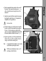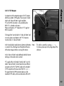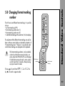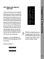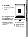
1
IVS 435 / II
Integrated Video-Assist System II for the ARRIFLEX 435
Instruction Manual
As of: August 2003
ALL ARTWORK, PICTURES AND TEXTS ARE COVERED BY OUR COPY-RIGHT.
THEY MUST NOT BE COPIED FOR REPRODUCTION (E.G. ON CD-ROM DISKS OR INTERNET-SITES) OR USED IN THEIR ENTIRE FORM OR IN EXCERPTS WITHOUT OUR PREVIOUS WRITTEN AGREEMENT.
IF YOU ARE DOWNLOADING PDF-FILES FROM OUR INTERNET HOME-PAGE FOR YOUR PERSONAL USE, MAKE SURE TO CHECK FOR UPDATED VERSIONS.
WE CANNOT TAKE ANY LIABILITY WHATSOEVER FOR DOWNLOADED FILES, AS TECHNICAL DATA ARE SUBJECT TO CHANGE WITHOUT NOTICE.
• Mini monitor connector
• Switch ON/OFF/Keyboard locked
• Manual gain control (ON)
• White balance (Indoor/Outdoor/Automatic/Manual)
• Flicker free (ON/OFF)
• Mode (Frame store / Compare)
• Store key
• Activate inserter onscreen menu or • store position of inserted windows
• Increase gain or • cursor up or • move inserted window up or • increase blue
• Go to sub menu or • move position of inserted windows right or • increase inserter values or
• increase red or • change format marking number
• Go to sub menu or • move position of inserted windows left or • reduce inserter values or
• reduce red or • change format marking number
• Decrease gain or • cursor down or • move inserted window down or • decrease blue
• ”Normal video” composite out or C
• ”Video with data” composite out or Y
• Genlock In
1. Contents ............................................................ 3
2. Safety Specifications ...................................... 5
3. General Description of the IVS ..................... 7
3.1 Main Features ............................................ 7
3.2 System Components ................................... 9
4. Setup ............................................................... 13
4.1 Inserting the Optic .................................... 13
4.2 Mounting the IVS ..................................... 15
4.3 Changing the Optic .................................. 19
4.4 Connections ............................................. 21
5. Standard Video Controls ........................... 27
5.1 On/Off and Locking the Keyboard ............ 27
5.2 Mechanical Iris ........................................ 28
5.3 Aligning the Image and Focusing .............. 29
5.4 White Balance (WB) ................................. 30
5.5 Gain Control ........................................... 35
5.6 Flicker Free on/off ................................... 38
5.7 Frame Store and Compare ........................ 40
5.8 Changing Format marking number ............ 43
6. Inserter Facilities ........................................... 45
6.1 Setting the On Screen Displays .................. 46
6.2 Main Menu .............................................. 47
6.3 Load/Store Menu ..................................... 48
6.4 Video Adjust Menu .................................. 53
6.5 Format Marking Menu .............................. 68
6.6 Status Menu ............................................. 73
6.7 TIME CODE Menu .................................... 81
6.8 USER BITS Menu ...................................... 87
6.9 Text Menu ................................................ 91
6.10 Pull-Down Menu .................................... 95
6.11 Display Menu ...................................... 101
6.12 VITC Line Menu .................................... 105
6.13 White Line Menu .................................. 109
Contents
1. Contents
7. Technical Data .............................................. 114
8. Order numbers ............................................ 114
9. Index ............................................................. 115
ARRI Service ...................................................... 121
3
4
Contents
Warnings
Note:
Operational error possible!
Danger of injury or
equipment damage possible!
General Safety Specifications
Attention! Danger of injury! Never place your
hand in the lens mount receptacle or the inside
of the camera or magazine while it is running.
• Assembly and initial operation should be carried out
only by persons who are familiar with the equipment!
• Remove all cables before transport or servicing!
• In order to ensure optimal performance, it is essential
that you acquaint yourself with this instruction manual,
and the manual of the ARRIFLEX 435.
• Repairs should be carried out only by authorized
service centers!
• Use the IVS only with ARRIFLEX 435 cameras, and
only as described in this manual.
• Use only original ARRI replacement parts and accessories!
Safety Specifications
2. Safety Specifications
• Check all operations on the corresponding monitor.
5
Safety Specifications
6
Important Notes
Product Specifications
• In wet weather the normal safety precautions for
handling electrical equipment should be taken.
In the case of inquiries or when ordering parts, please
advise serial number and model.
• Avoid operational errors!
• Do not touch optical surfaces!
• Clean optical surfaces only with a lens brush or a
clean lens cloth! In cases of solid dirt moisten a lens
cloth with pure alcohol.
• Do not use solvents in cleaning!
• Do not use force!
• Do not remove any screws which are secured with paint!
Explanation of the Symbols
in the Instruction Manual
§ indicates objects which are shown in the
photographs or drawings.
The Integrated Video-Assist System (IVS) for the ARRIFLEX
435 responds to a strong request from camera users and
integrates a complete video assist system totally into the
camera body. It offers unsurpassed image quality combined with a state-of-the-art inserter to add frame lines,
time code and text to the video image. Colors can be set
to fixed values or controlled manually or automatically.
3.1 Main Features
• Integrated into the camera body
Instead of a bulky add on, the video assist becomes an
integrated part of the camera without additional cabling.
• High sensitivity
A high speed lens with an aperture of 1 : 1.4 and one
of the most sensitive CCD-Chip available on the market
provide an excellent color video image in editing quality
even when the light was set for a high speed film stock,
which will be pushed during processing.
• High resolution
The design of the new IVS optics was based on the
435´s view finder data and resulted in an image quality
which can not be realized by add on solutions.
• Flicker-free
An integrated digital frame store enables the video
camera to be synchronized to the film camera´s mirror
shutter and provides a flicker-free video image from 1 fps
to maximum speed (in manual gain control mode)
because the video image is always taken at the ideal
position of the mirror shutter.
Flicker free can be switched off to bypass the digital frame
store and have the video assist output with no delay.
General Description
3. General Description of the IVS
• Full manual white balance
In addition to the standard indoor white balance setting
with 3200 K, an outdoor setting with 5600 K and
automatic adjustment, color can be fine tuned with a
separate red and a separate blue channel for manual
white balance.
7
General Description
• Even further resolution in camera run mode
Video images are now also in the camera run mode in
almost full video resolution due to a new technology.
• New video exposure time mode ‘identical with film exposure’
The exposure time of the video assist can be programmed
to follow the exposure time of the film. Thus, identical
motion blur on film and video assist is achieved.
• Store and recall for all settings
All settings can be stored and recalled. By this, it is possible
for example to trim all the settings for indoor shooting,
store them, have some exterior scenes, go back indoor
and call the old settings back.
Up to 6 sets of settings can be stored.
• Integrated frame line inserter
Frame lines can be electronically added to the video image.
This ensures that the lines are visible even in difficult
conditions. The area outside of the frame lines can be
darkened electronically to emphasize the important
image area.
• Integrated time code inserter
It is possible to insert Time code into the video image.
Thus, the video assist creates a reliable link to video
editing. The information on ”3:2” pull-down, which
8
can be inserted as well, ensures the same reliability in
an NTSC environment.
• Integrated text inserter
Additional text like take numbers or production name
can be added to the video image by sending characters
on a serial interface.
• Two additional Y/C Outputs
In addition to the usual composite outputs, the IVS offers
a Y/C output (S-VHS) for an even better video image
without annoying color artifacts with or without data
inserted into the video image. The output is on a standard
S-VHS connector as well as on two BNC sockets.
• On-Screen programming
All functions, which do not effect the image appearance
directly like gain control, can be conveniently programmed
with an onscreen programming menu on the video monitor.
• Full remote controllable
All settings can be controlled directly on the IVS as
well as via RS 232 with the remote control software
(under development)
• Image compare function
It is possible to store a particular image and compare
3.2 System Components
• Automatic and manual gain control
The gain is controlled automatically to its best value
but can also be set manually.
• Optic Silent and/or ................................. K2.47230.0
• External synchronization input (Genlock)
The IVS has an external synchronization input to enable
multi camera use.
• Video Electronic complete ............. K2.47365.0 for PAL
or K2.47366.0 for NTSC
• Mini monitor connector
The IVS offers a connector for a 12 V LCD mini
monitor combined with a 1.1 A power supply.
• Optic Academy ...................................... K2.47231.0
The Video Electronic complete consists of two parts:
• CCD Optic Module
• Inserter / Antiflicker Module
• Software for text input ............................... On request
Note:
All ARRIFLEX 435 versions (435, 435 ES and
Advanced) can be equipped with the IVS
independently of the expanded function module.
However, the time code functions such as insertion
of time code, user bits, pull-down information,
VITC and white line flags can only be activated
if the expanded function module is installed.
General Description
it against other images. This clearly shows the difference
between the images e.g. during stop effect shots.
As the IVS is designed for an 80 : 20 beam splitter, there
is no need for the 50 : 50 beam splitter, which is used for
other color video assists.
9
General Description
10
3.2.1 Optic Silent
3.2.2 Optic Academy
For a complete and working IVS, either the optic silent or
the optic acacemy has to be installed inside the CCD optic
module. They can be easily exchanged.
For a complete and working IVS, either the optic silent or
the optic acacemy has to be installed inside the CCD optic
module. They can be easily exchanged.
The optic silent forms an image on the CCD chip which is
based on the 35 mm silent format with a picture width of
24 mm. An additional area will surround the actual image.
This is to check for important objects outside the image area.
The optic academy forms an image on the CCD chip which
is based on the 35 mm academy format with a picture width
of 22 mm. An additional area will surround the actual image.
This is to check for important objects outside the image area.
The lenses are especially designed and built for the use with
the ARRIFLEX 435 to achieve the best possible image quality.
Especially the aperture of 1 : 1.4 is important for the use
as video assist lenses because only a small portion of the
light that goes through the camera lens reaches the video
chip. Therefore the lenses are not designed as zoom lenses
because it would be impossible to get the same image
quality and speed.
The lenses are especially designed and built for the use with
the ARRIFLEX 435 to achieve the best possible image quality.
Especially the aperture of 1 : 1.4 is important for the use
as video assist lenses because only a small portion of the
light that goes through the camera lens reaches the video
chip. Therefore the lenses are not designed as zoom
lenses because it would be impossible to get the same
image quality and speed.
All silent optics are marked with an S in the serial number,
e.g. S0040.
All academy optics are marked with an N in the serial number,
e.g. N0040.
There are no different lenses for PAL and NTSC.
There are no different lenses for PAL and NTSC.
3.2.4 Inserter / Antiflicker Module
The CCD optic module, which is mounted on the ARRIFLEX 435
view finder system has to be equipped with a video lens.
This module contains the CCD-chip and all the necessary
elements to center the video image on the TV-Monitor screen
and to adjust the focus. It houses also a video pre-amplifier
to increase the sensitivity of the IVS at low light conditions.
The Inserter/Antiflicker module contains most of the IVS
electronics. This 22 mm wide module, which is mounted on
the right side of the ARRIFLEX 435, holds the video camera
electronic, an anti flicker processor and the entire inserter.
All control elements, which are often used, as well as all
in- and outputs are located here.
The CCD optic module is available in PAL and NTSC.
The Inserter/Antiflicker module is available in PAL and NTSC.
It is necessary to keep the combination of CCD optic module
and Inserter/Antiflicker module together as delivered.
Mixing the modules might lead to a reduced image quality.
On request ARRI can supply a second CCD optic module
optimized for a particular Inserter/Antiflicker Module.
It is necessary to keep the combination of CCD optic module
and Inserter/Antiflicker module together as delivered.
Mixing the modules might lead to a reduced image quality.
On request ARRI can supply a second CCD optic module
optimized for a particular Inserter/Antiflicker module.
General Description
3.2.3 CCD Optic Module
11
12
Setup
4. Setup
4.1 Inserting the Optic
cap •
For a complete and working IVS, either the optic silent or
the optic academy has to be installed inside the CCD
optic module.
A 1.5 mm allen key is used.
Do not touch optic surfaces.
All lenses must be clean.
Do not use force.
S1
S2
S3
a) Remove the cap, which is located at the end of the
module § by twisting it counter clockwise to
get access to the alignement screws.
b) Make sure that the focus screw (S3) § is in the
middle of its range.
S4
13
Setup
c) Insert the optic with the bayonet first into the CCD
optic module. Make sure that the key is aligned with
the key way §.
d) Press the optic carefully into the mount and rotate clock
wise to the stop. Make sure that the key is on the right
side of the lens securing spring.
e) To release the optic rotate carefully counter clock wise
until loose and remove forward.
f) Reattach the cap at the end of the CCD optic module.
• key
14
• 3 screws
The following tools are needed to mount the IVS:
Setup
4.2 Mounting the IVS
3 mm allen key
0.5 x 3.5 mm screw driver (first time installation only)
2.5 mm allen key
1.5 mm allen key
As there is a vertical connector between the CCD optic
module and the Inserter/Antiflicker Module, it is necessary
to take the view finder system off the ARRIFLEX 435
before the IVS is installed.
The CCD optic module is mounted on the right side of the
ARRIFLEX 435 view finder system:
Disconnect camera of all power supplies.
Support the viewfinder system.
Do not touch optic surfaces.
a) Remove the view finder system by loosening the three
mounting screws §.
For the initial installation of the IVS on the ARRIFLEX 435 it
may be necessary to exchange the flange, which is mounted
on the view finder system of the ARRIFLEX 435. The IVS is
delivered with a modified flange that can hold the IVS as
well as other video-assists. This new flange remains on
the ARRIFLEX 435. Therefore it is not necessary to remove
it when the IVS is taken off.
15
Setup
b) Remove the protection cap of the video tap ➪ photo.
Note:
Step c) is only necessary for the initial installation
of the IVS. If the flange is already modified with
three additional threads, proceed with step d).
c) Remove the old flange by taking out the four screws
§ and mount the new flange.
Make sure that the pin is aligned with the bore hole.
Put the four screws back and close them.
protection cap •
d) Insert the CCD optic module and mount it with three
screws § at the new flange.
4 screws •
3 screws •
• 3 threads
flange, old version
16
flange, new version
• pin
Setup
e) Take the expanded function module or the cover off
the camera. To do so open the mounting screw §
with a 3 mm allen key and swing the cover or the
module off.
screw •
f) Attach the Inserter/Antiflicker module to the camera
by placing the registration-pins in the appropriate
receptables and swing module on.
Do not use force
g) Close the mounting screw with the same 3 mm allen
key that is used for the extended function module or
the cover. Turn the mounting screw back until the
square screw head is aligned parallel to the profile of
the Inserter/Antiflicker module as illustrated §.
square screw head
• receptables
parallel to
outer profile •
h) Align the registration pins of the expanded function
module or the cover with the receptables of the IVS,
swing on, and close the mounting screw.
Note:
An expanded function module or cover must be
in place before operating the camera.
With the cover attached only, there is no TCrecording or related functions.
17
Setup
i) Place the view finder system back on the camera body
and close the three mounting screws.
Ensure clean contacts.
Do not use force.
Note:
18
Because of the high speed video optic (Academy
or Silent), it is no longer necessary to use a 50 : 50
beam splitter, as it was with other color video
assists. The IVS is designed to work with a 80 : 20
beam splitter.
• 3 screws
For exchanging the optic between academy and silent
format, it is necessary to take the view finder system off
the camera in order to remove the CCD optic module.
The following tools are necessary:
3 mm allen key
2.5 mm allen key
1.5 mm allen key.
Setup
4.3 Changing the Optic
Disconnect camera of all power supplies.
Support the viewfinder system.
Do not touch optic surfaces.
All lenses must be clean.
Do not use force.
a) Take the view finder system off the camera by loosening
the three mounting screws §.
b) Remove the CCD optic module by opening the three
screws §.
c) Remove the cap, which is located at the end of the
module § by twisting it counter clockwise to
get acess to the alignement screws.
3 screws •
cap •
19
Setup
S1
S2
S3
d) Make sure that the focus screw (S3) § is in the
middle of its range.
e) To release the optic rotate carefully counter clock wise
until the key is on the other side of the spring and the
optic gets loose. Remove forward.
f) Insert the new lens with the bayonet first into the CCD
optic module. Make sure that the key is aligned with
the key way §. Press the lens slightly into the
module and rotate clockwise to the stop. Make sure
that the key is on the right side of the lens securing spring.
S4
g) Reattach the cap at the end of the CCD optic module
h) Mount the CCD optic module back to the view finder
system with the three screws.
i) Put the view finder system back onto the camera and
tighten the three mounting screws.
• key
20
Setup
4.4 Connections
4.4.1 Outputs
In case that the composite output should be used
and it is unknown, weather the BNC connectors
on the IVS are switched to composite or to Y/C,
please connect the composite signal to the ”OUT 1”
output first and check the setting (BNC Y/C or
composite) in the menu first.
Please see chapter 6.4.9 ”Composite or Y/C
signal at BNC Connectors”
The IVS has two separate outputs for composite video,
two outputs for Y/C and one output for a mini monitor.
The Y/C signal can be taken from the standard S-VHS
connector on the lower side of the IVS or in the Y/C mode
on the two BNC connectors that supply the composite
signal, when the Y/C mode is off.
21
Setup
4.4.1.1 Composite Video Outputs
Make sure that Y/C mode is switched off to get
composite video signal out of the BNC connectors.
See chapter 6.4.9 ”Composite or Y/C signal at
BNC Connectors”
The difference between the outputs is that there is ”normal
video” on one connector and ‘video with data’ on the other.
In the ”normal video” output, which is marked with the
”OUT 2” symbol §, almost no electronic information
is inserted. Only a flashing bar at the button left corner of
the video image indicates a running film camera.
In the ”video with data” output, which is marked with the
”OUT 1” symbol §, additional data like format
marks or time code can be inserted.
• Composite Video Outputs
22
Spring •
Y/C Output •
In comparison to the composite outputs, the Y/C outputs
offer the even better S-VHS quality. There are also ”normal
video” and ”video with data” signals available.
Y/C on the BNC connectors is only available when
BNC Y/C is selected on the menu.
Please see chapter 6.4.9 ”Composite or Y/C signal at
BNC Connectors”.
Setup
4.4.1.2 Y/C Outputs
To change from ”normal video” to ”video with data” and
vice versa, please see chapter 6.4.8 ”Y/C-Output as
‘normal video’ or ‘video with data’ ”.
In the ”normal video” mode almost no electronic information
is inserted. Only a flashing bar at the bottom left corner
of the video image indicates a running film camera.
Note:
This cable is secured by a spring §.
To release, please press the spring and pull the
cable out.
In the ”video with data” mode additional data like format
markings or time code can be inserted.
Y/C signals either in the mode ”normal video” or in the
mode ”video with data” can be taken from two different
connectors on the IVS: The BNC sockets or the standard
S-VHS connector on the lower side of the IVS §.
For signals from the S-VHS connector please use the
standard S-VHS cable, which was delivered with the IVS.
23
Setup
Alternatively, the Y/C signal can be taken from the two
BNC outputs on the rear side of the IVS.
For this, it is necessary to switch the BNC output from
composite to Y/C, using the menu.
Please see chapter 6.4.9 ”Composite or Y/C signal at
BNC Connectors”. Use the 3-way cable, with was delivered
with the IVS. Connect the red BNC connector to ”OUT 2”
and the white connector to ”OUT 1”.
• BNC connectors
24
Note:
For a standard black and white signal, use only
the Y Signal. To do so, switch the BNC output to
Y/C and connect a standard composite BNC
cable to ”OUT 1”.
Note:
In some combinations of accessory, e.g. single
frame control of the Integrated Capping Shutter,
the standard S-VHS cable in the Y/C connector
on the bottom side of the IVS might collide with
the additional accessory. In this case, please
use the BNC outputs for Y/C signal, as described above.
Setup
4.4.1.3 Mini-Monitor Output
The IVS has a connector for a standard mini-monitor
§.
As there is only one mini monitor connector, it is possible
to switch between ”Normal Video” and ”Video with
Data” on this output: To do so, please use the on-screen
display menu. Please see chapter 6.4.7 ”Mini-Monitor
Output as ”normal video” or ”video with data”.”
Composite Video Pin 3
Pin 2 Signal Shield
+ 12 V (1.1 A max.) Pin 4
Pin 1 GND
Pin-Outs Mini-Monitor Connector
(seen from outside)
25
Setup
4.4.2 Inputs
It is possible to synchronize the IVS to an external video
source. Furthermore, the IVS can be remote controlled by
a computer.
4.4.2.1 Genlock
The genlock input § allows the IVS to be synchronized to an external video source. This is necessary if
several video cameras are used together.
Input is a standard composite video signal.
4.4.2.2 Remote Control
All inserter functions of the IVS, which can be called or set
with the on screen menu, can also be controlled via the
film camera’s CCU interface.
A corresponding software for the ARRI Laptop Camera
Controller is available on request (refer to seperate manual).
• Genlock Input
26
The IVS can be used like a standard Video Assist if no
inserter functions are used.
Note:
Note:
For exchanging the optic between academy and
silent format, refer to chapter ”4.3 Changing
the Optic”.
All currently used settings are stored even if the
IVS or the camera is switched off. After restarting
the IVS the settings are unchanged.
5.1 On/Off
and Locking the Keyboard
The IVS can be switched on and off independently of the
film camera.
• Switch
Standard Video Controls
5. Standard
Video Controls
The ”OFF” position switches the IVS off without affecting the
film camera. ”ON” activates the IVS and ”LOCK” disables
the keyboard to prevent unintentional handling §.
27
Standard Video Controls
28
5.2 Mechanical Iris
• Adjustment ring
Only a relatively small portion of the light which goes
through the film cameras´s lens reaches the CCD-Chip of
the video assist as the light is shared between the view
finder, the CCD-Chip and the film. Therefore the IVS
lenses are designed for a normal usage with a totally
open iris to have maximum light on the CCD-Chip.
Variations in lighting are compensated by the IVS´s gain
control (automatically or manually).
Under certain conditions, such as when lighting is set for
low-sensitivity film (under 100 ASA) or for motion effects,
it is possible that the IVS´s gain range is exceeded. In this
case the mechanical iris of the IVS lens can be closed.
Check all settings on the connected monitor.
If the mechanical iris is closed more than
necessary, the IVS will compensate by increasing
the gain and improve the image brightness
electronically. This creates additional electronic
noise. Avoid that by opening the mechanical iris.
The position of the image on the CCD-Chip can vary slightly
from film camera to film camera. The video image on the
monitor may appear not centered. In addition to that, it is
necessary to focus the lens on every new film camera.
• cap
All settings can be made by using a 1,5 mm allen key.
Do not use force.
Both adjustments can be done on the CCD optic module.
Remove the cap, which is located at the end of the module
§ by twisting it counter clockwise to get access to
alignment screws.
Screw S 1 moves the video image on the monitor horizontally.
Screw S 2 rotates the image around a point which is located
in the middle of the left side and screw S 4 rotates the image
around a point which is located in the middle of the right side.
Screw S 3 will focus the lens. Reattach the cap after adjusting.
Note:
S1
S2
S3
Standard Video Controls
5.3 Aligning the Image
and Focusing
S4
Make sure that the iris is fully open during
focusing in order to optimize focus.
29
Standard Video Controls
5.4 White Balance (WB)
ON
IND
OTD
ATW
WB
• White Balance Key
MAN
ON
FR
• Auto White Balance selected
White balance can be adjusted in two different ways. It is
possible to control it using the keyboard on the IVS or
using the on-screen control menu.
STO
CMP
MODE
• Indoor selected
ON
MGC
IND
OTD
ATW
WB
ON
MGC
OTD
ATW
WB
MAN
FR
STO
CMP
• Outdoor selected
IND
MAN
ON
30
The IVS offers a choice for White Balance between
• an automatic control (ATW),
• a fixed setting of indoor (IND)
• a fixed setting of outdoor (OTD)
• and a full manual control of white balance.
MGC
ON
FR
STO
MODE
CMP
MODE
5.4.1 Using the Keyboard
By pressing the key WB §, the setting will be
changed from IND, OTD, ATW, to MAN. The next click
on the WB-Key will cause the MAN-LED to blink. Thus, it
is possible to change the red and blue channel using the
, , and key. The next click on the WB key will
cause the MAN-LED to be constantly on. Another click on
the MAN-LED will lead back to IND. An illuminated LED
shows the selected mode.
Check all settings on the connected monitor.
ON
IND
OTD
ATW
Manual selected •
To access the manual setting, press the WB key §
until the MAN LED is on. By pressing the WB key again, the
MAN LED will blink, indicating, that the manual white
balance mode is active. Now the red of the video image can
be increased, using the color coded red key or reduced
using the key. Blue can be increased by using the color
coded blue key or reduced by using the . By either
waiting more the 5 seconds or pressing the WB key again,
the MAN LED will stop blinking and is constantly on,
showing that the color setting is manual.
Note:
MGC
WB
• White Balance Key
MAN
ON
FR
STO
CMP
MODE
STO
ENTER
INSERT
With the MAN LED constantly on, no color
settings can be made to avoid accidental handling.
• Color coded keys
Note:
Changing green is done by changing red, blue
and gain. The video singal is the addition of
red, green and blue and amplified by the gain.
Increasing green can be done by decreasing
red and blue and increasing gain.
Standard Video Controls
• If automatic White Balance (ATW) is selected §,
the IVS will automatically set White Balance.
For this no manual steps are necessary.
• If indoor (IND) is selected §, white balance is
optimized for tungsten lighting with 3200 K.
• The outdoor (OTD) setting § optimizes the
white balance for daylight with 5600 K.
31
Standard Video Controls
32
5.4.2 Using the on screen menu
SUB MENU
VID ADJ
MGC
OFF
-VALUE
> WB
MAN
-RED
30
-BLUE
39
EXPOSE
1800
MM- DAT
ON
Y/C-DAT
ON
BNC-OUT
VBS
FR
ON
LINE
INTEREP.ON
MODE
LIVE
-STORE
EXIT
Please see the chapter 6 ”Inserter Facilities” for basics on
the on-screen display.
White Balance
In parallel to the control via keyboard, the white balance
can also be programmed via the on-screen menu. It toggles
from indoor, outdoor and automatic to manual.
Call the sub menu VID ADJ.
> WB
IND
> WB
OTD
> WB
ATW
> WB
MAN
> WB
-RED
-BLUE
MAN
30
39
Move the cursor > with the keys and to the line
WB. Pressing the key will switch from indoor, outdoor
and automatic to manual and back to indoor. The key
will give the opposite direction.
If white balance is on manual, the display will change.
Figures will appear in the line -RED and -BLUE,
indicating the red and green saturation of the video
image.
Manual white balance red increase/decrease
is only available if white balance control is on
manual.
If manual white balance is on MAN, it is possible to adjust
the red and blue saturation of the video image manually.
Move the cursor > with the keys and to the line
-RED. Pressing the key will increase the red in the
video image, the key will decrease it.
The range for this is from 0 (lowest) to 63 (highest).
If the key or is pressed shortly, the value is changed
by one step, if the keys are pressed longer, the value will
continue to change.
The LED in the keyboard will follow the changes which are
made in this menu and vice versa, if this setting is changed
via the keyboard, the on-screen menu will follow.
SUB MENU
VID ADJ
MGC
OFF
-VALUE
WB
MAN
> -RED
30
-BLUE
39
EXPOSE
1800
MM- DAT
ON
Y/C-DAT
ON
BNC-OUT
VBS
FR
ON
LINE
INTEREP.ON
MODE
LIVE
-STORE
EXIT
Standard Video Controls
Manual White Balance red increase/decrease
33
Standard Video Controls
34
SUB MENU
VID ADJ
MGC
OFF
-VALUE
WB
MAN
-RED
30
> -BLUE
39
EXPOSE
1800
MM- DAT
ON
Y/C-DAT
ON
BNC-OUT
VBS
FR
ON
LINE
INTEREP.ON
MODE
LIVE
-STORE
EXIT
Manual White Balance blue increase/decrease
Manual white balance blue increase/decrease
is only available if white balance control is on
manual.
If manual white balance is on MAN, it is possible to adjust
the red and blue saturation of the video image manually.
Move the cursor > with the keys and to the line
-BLUE. Pressing the key will increase the blue in
the video image, the key will decrease it.
The range for this is from 0 (lowest) to 63 (highest).
If the key or is pressed shortly, the value is changed by
one step, if the keys are pressed longer, the value will
continue to change.
The LED in the keyboard will follow the changes which are
made in this menu and vice versa, if this setting is changed
via the keyboard, the on-screen menu will follow.
The IVS can control the brightness of the video image
electronically. This gain control can be automatic or manual.
If the automatic control is selected, the IVS outputs the best
possible image brightness at all the time. Light changes in
front of the film camera are compensated by the IVS, the
brightness impression remains almost unchanged.
Gain control can be adjusted in two different way. It is
possible to control it using the keyboard on the IVS or
using the on-screen control menu.
ON
OTD
ATW
WB
MAN
ON
FR
STO
5.5.1 Using the Keyboard
By pressing ”Manual Gain Control” (MGC) the setting alters
between manual and automatic control. An illuminated
LED shows the setting Manual Gain Control.
• Manual Gain Control Key
IND
CMP
The brightness of the video image can be manually altered
if manual gain control is selected. By using the color coded
blue keys Manual Gain Control (MGC) or Manual Gain
Control (MGC) the brightness can be increased or
decreased. An automatic compensation of different light
levels in front of the camera is suppressed.
MGC
MODE
STO
ENTER
INSERT
• Manual Gain Control + Key
Standard Video Controls
5.5 Gain Control
• Manual Gain Control - Key
Check all settings on the connected monitor.
35
Standard Video Controls
5.5.2 Using the on screen menu
SUB MENU
VID ADJ
> MGC
OFF
-VALUE
WB
MAN
-RED
30
-BLUE
39
EXPOSE
1800
MM- DAT
ON
Y/C-DAT
ON
BNC-OUT
VBS
FR
ON
LINE
INTEREP.ON
MODE
LIVE
-STORE
EXIT
Please see the chapter 6 ”Inserter Facilities” for basics on
the on-screen display.
Manual Gain Control
In parallel to the control via keyboard, the manual gain
control can also be programmed via the on-screen menu.
Manual gain control can be switched on or off. If it is on,
specific values can be set between 0 (low gain) and 63
(high gain).
Call the sub menu VID ADJ.
> MGC
-VALUE
ON
32
Move the cursor > with the keys and to the line
MGC. Pressing the key or will switch manual gain
control off and on.
If manual gain control is on, the display will change.
Figures will appear in the line -VALUE, indicating the gain.
The LED in the keyboard will follow the changes which are
made in this menu and vice versa, if this setting is changed
via the keyboard, the on-screen menu will follow.
36
Manual gain increase/decrease is only available
if manual gain control is on.
Move the cursor > with the keys and to the line
-VALUE. Pressing the key will increase the gain,
the key will decrease it.
The range for this is from 0 (lowest gain) to 63 (highest gain).
If the key or is pressed shortly, the value is changed by
one step, if the keys are pressed longer, the value will
continue to change.
The LED in the keyboard will follow the changes which are
made in this menu and vice versa, if this setting is changed
via the keyboard, the on-screen menu will follow.
SUB MENU
VID ADJ
MGC
ON
> -VALUE
32
WB
MAN
-RED
30
-BLUE
39
EXPOSE
1800
MM- DAT
ON
Y/C-DAT
ON
BNC-OUT
VBS
FR
ON
LINE
INTEREP.ON
MODE
LIVE
-STORE
EXIT
Standard Video Controls
Manual Gain increase/decrease
37
Standard Video Controls
38
5.6 Flicker Free on/off
ON
The IVS suppresses the flickering of the video image,
which normally occurs when the film camera and the
video camera are running at different frame rates or if
they are not in phase. This is done using a frame store.
MGC
IND
OTD
ATW
WB
MAN
ON
FR
STO
CMP
MODE
STO
ENTER
INSERT
• Flicker Free on
Under critical conditions, like motion control, where it is
not desirable to have any time delay between the live action
in front of the camera and the video assist image, it might
be helpful to switch the frame store off. This, the image
will flicker again.
The time code information is not valid if flicker
reduction is switched off.
Flicker Free on/off can be adjusted in two different ways.
It is possible to control it using the keyboard on the IVS or
using the on-screen control menu.
The flicker reduction key § switches the anti flicker
facility on and off should this become necessary.
The LED indicates flicker free on.
Note:
The lowest camera speed for flicker free display
is 5 FPS in automatic gain control mode,
and 1 FPS in manual gain control mode.
5.6.2 Using the on screen menu
Please see the chapter 6 ”Inserter Facilities” for basics on
the On-Screen display.
Flicker free
The time code information such as time code,
user bits, VITC and white line is not valid if
flicker reduction is switched off.
SUB MENU
VID ADJ
MGC
ON
-VALUE
32
WB
MAN
-RED
30
-BLUE
39
EXPOSE
1800
MM- DAT
ON
Y/C-DAT
ON
BNC-OUT
VBS
> FR
ON
LINE
INTEREP.ON
MODE
LIVE
-STORE
EXIT
Standard Video Controls
5.6.1 Using the Keyboard
Call the sub menu VID ADJ.
Move the cursor > with the keys and to the line FR.
Pressing the key or will switch flicker free on or off.
39
Standard Video Controls
40
5.7 Frame Store and Compare
ON
The IVS can store one video image and compare it
against the currently incoming images. Frame store and
compare can be adjusted in two different ways. It is
possible to control it using the keyboard on the IVS,
or using the on-screen control menu.
MGC
IND
OTD
ATW
WB
MAN
ON
FR
5.7.1 Using the Keyboard
STO
CMP
MODE
STO
ENTER
INSERT
• Mode Key
• Store Key
By pressing the key STO it is possible to grab one video
image. To display stored video images, activate the frame
store mode by pressing the key MODE. The STO LED is
illuminated indicating the store mode.
The image remains only stored
until another frame is stored, or
until the IVS or the film camera is switched off
or disconnected from the power supply.
To activate the compare mode press the key MODE after
one image was stored. The illuminated CMP LED indicates
this mode. The stored image is superimposed with the
presently incoming video image. Differences between the
two images can be easily seen.
5.7.2 Using the on screen menu
Please see the chapter 6 ”Inserter Facilities” for basics on
the on-screen display.
SUB MENU
VID ADJ
MGC
OFF
-VALUE
WB
MAN
-RED
30
-BLUE
39
EXPOSE
1800
MM- DAT
ON
Y/C-DAT
ON
BNC-OUT
VBS
FR
ON
LINE
INTEREP.ON
> MODE
LIVE
-STORE
EXIT
Display Mode
Please see next paragraph ”Store image” for how to store
one image.
Call the sub menu VID ADJ.
Move the cursor > with the keys and to the line
MODE. Pressing the key will switch from LIVE to
STO to CMP and back to LIVE. The key will give
the opposite direction.
If LIVE is selected, the actual image will be displayed.
If STO is selected, an image, which was stored before,
will be displayed and if CMP is selected, a live image
and a stored image will alternate to show the difference
of both images.
The stored image is memorized until a new image is
stored or until the IVS power was shot down.
Standard Video Controls
By pressing the key MODE the IVS goes from normal mode to
store mode to compare mode and back to normal mode.
Every time the key STO is pressed with the IVS in store
mode, a new video frame is grabbed.
41
Standard Video Controls
42
SUB MENU
VID ADJ
MGC
OFF
-VALUE
WB
MAN
-RED
30
-BLUE
39
EXPOSE
1800
MM- DAT
ON
Y/C-DAT
ON
BNC-OUT
VBS
FR
ON
LINE
INTEREP.ON
MODE
LIVE
> -STORE
EXIT
Store image
Please see paragraph above, ”Display mode”, for information
on different display modes, e.g. live, store and compare.
Call the sub menu VID ADJ.
Move the cursor > with the keys and to the line
-STORE. Pressing the key or will store one
particular image into the frame store. The line will change
DONE
for 1 second to > -STORE
. To store a new
video image, leave the line -STORE and go back to
this line.
The stored image is memorized until a new image is
stored or until the IVS power was shot down.
ON
IND
The IVS can insert different format markings. It is possible
to have
• no format marking (OFF),
• format marking number one (1),
• format marking number two (2)
• or both format markings at the same time (1 & 2) on display.
OTD
ATW
WB
MAN
ON
FR
STO
CMP
The adjustment of the different format markings can only be
done via the on-screen display as described in chapter 6.5
”Format marking menu”. However, it is possible to select
which format markings are displayed via the keyboard.
The format marking selection is only available,
when the white balance manual mode is not
active (when the WB MAN LED is not flashing).
If white balance manual mode is active, please
wait for more than 5 seconds without pressing
any key to leave this mode.
MGC
MODE
STO
ENTER
INSERT
Select format
marking •
• Select format
marking
Standard Video Controls
5.8 Changing Format marking
number
The key will switch from OFF, 1, 2 to 1&2. The
key will switch in opposite order.
43
44
Standard Video Controls
All inserted data are only available at the
outputs ”Video with data”.
All engravings from the ground glass
(i. e. TV-Safe etc.) are visible at all times at all
outputs.
In addition to the usual video assist functions, the IVS offers
a variety of inserter facilities. There are three different groups
of information:
• Format markings
Format markings, which are inserted electronically,
are often more visible than format markings on the
ground glass or on the ARRIGLOW.
• Man readable information
Time code
User Bits
Camera status
IVS Film Counter
Additional text
Pull-down information
Note:
All currently used settings are stored even if the
IVS or the camera is switched off or disconnected
from the power supply. After restarting the IVS
the settings are unchanged.
Inserter Facilities
6. Inserter Facilities
• Machine readable information
VITC
White Line Flag
45
Inserter Facilities
Pressing the key or
down. Pressing the key
STO
ENTER
INSERT
• Key Enter Insert
• An illuminated LED indicates that
the onscreen programming is
activated
Within sub menus the cursor > can be moved up and
down again by pressing the key or . The keys or
will now change settings (e. g. switch the insertion of a
time code window on and off), or activates functions
(position mode of a window, EXIT or the
ALL STANDARD call).
If the windows position mode is activated, the keys , ,
or will move the window across the video image. To
leave the position mode press the key ”Enter Insert” shortly.
6.1 Setting the On Screen Displays
During programming the inserted data are not
fully updated (i. e. Pull-down information, TCFrame Count). To get information updated, leave
the onscreen display menu by pressing the key
”Enter Insert” for more than three seconds.
Once the onscreen display is activated by pressing the key
”Enter Insert” for more than three seconds, the following
procedure is used to select and set all functions within the
main menu and the sub menus:
46
will move the cursor > up or
or activates sub menus.
To go from a sub menu back to the main menu, position
the Cursor > by using the keys and on the line
EXIT and press the key or .
All settings are immediately activated by
changing them.
Note:
Pressing the ENTER INSERT-key for more than three
seconds will cause the system to exit the onscreen
programming mode completely, regardless of
which menu is activated, with the exeption of
the positioning mode.
The inserter´s main menu is displayed on the monitor
screen when the on-screen programming is activated by
pressing the ENTER INSERT-key § for more than three
seconds.
An illuminated LED indicates that the onscreen programming is activated.
Note:
Pressing the ENTER INSERT-key for more than three
seconds will cause the system to exit the onscreen
programming mode completely, regardless of
which menu is activated, with the exeption of
the positioning mode.
MAIN MENU
> LOAD/STORE
VIDEO ADJUST
FORMAT MARKING
STATUS
TC TIME
TC USER BIT
TEXT
PULL DOWN
DISPLAY
VITC LINE
WHITE LINE
T.V. SAFE / TRANSMITTED
Inserter Facilities
6.2 Main Menu
The keys or move the cursor > up or down.
Pressing the key or will lead into a sub menu.
47
Inserter Facilities
6.3 Load/Store Menu
SUB MENU
> LOAD SET
STORE SET
(CONFIRM
BY E)
4
5
ALL
STANDARD
EXIT
T.V. SAFE / TRANSMITTED
The IVS can store up to 6 sets of settings and recall them.
Thus it is possible to make all settings for e.g. indoor shooting
and store them as setting 1. Shooting continues with some
exterior scenes and the operator will make all settings for this
and store them as setting 2. When the work is continued
indoor, it is very easy recalling all the settings stored as
setting 1 and get the same image appearance as before.
One set of settings consists of all set-ups in the IVS. Everything
which can be set electronically, will be stored and recalled.
All video adjustments such as manual gain control, white
balance, flickerfree, display mode, exposure mode, outputs
with or without data and line interpolation as well as all
inserter setups, e.g. Time Code insertion off or on, framelines
and so on are stored and recalled.
The adjustment of the white level of the inserted data, an inverse
display and a fine adjustment is described in chapter 6.11
All settings are immediately activated by
changing them.
Check all settings on the connected monitor.
• Enter the Load/Store submenu from the Main menu.
48
SUB MENU
> LOAD SET
It is possible to load one out of six settings. Those new settings
will influence all adjustments, that can be made electronically.
The new settings will immediately replace the
previous settings. If the old settings might be
needed, store them first as described in the next
chapter ”Store Settings”.
Move the cursor > with the keys and to the line
LOAD SET. Pressing the key will switch from 1 to
2 all the way up to 6 and back to 1, the key will
switch in the opposite direction. Pressing either the key
or , will immediately load the new settings.
STORE SET
(CONFIRM
BY E)
ALL
STANDARD
EXIT
4
5
Inserter Facilities
6.3.1 Load Settings
49
Inserter Facilities
50
6.3.2 Store Settings
SUB MENU
LOAD SET
> STORE SET
(CONFIRM
BY E)
ALL
STANDARD
EXIT
4
5
The set of settings, that is currently active, can be stored
as one out of six settings.
Move the cursor > with the keys and to the line
STORE SET. Pressing the key will switch from 1
to 2 all the way up to 6 and back to 1, the key will
switch in the opposite direction.
When the cursor is positioned on the line STORE SET
and the key or was pressed, the display will change from
> STORE SET
5
to > STORE SET 5 E
,
indicating, that by pressing the ENTER INSERT-key, the
current settings will be stored, e.g. as setting 5. After that,
the display changes again to > STORE SET 5 DONE ,
indicating that the settings are stored.
This menu recalls a default setting of all inserter values.
By this, it is possible to obtain basic setting for the IVS.
The default values are:
Format marking 1, White Level 2, Outside Full
Time-Code ON, Size Big, Background Boxed, Counter Film
USER-BITS On, Size Big, Background Boxed
Status On, Size Small, Background Boxed, IVS film counter OFF
Text Off, Size Small, Background Boxed
Pull down OFF, Size Big, Background Boxed
Vertical Position 5, White Level 2, Inverse OFF
VITC On, Position 1 - 10, Position 2 - 12
White Line On, Position 11
Move the cursor > with the keys and to the line
ALL. Pressing the key or recalls the default values.
If the ALL STANDARD function was called, it is
possible immediately recall the values back, that were set
before the ALL STANDARD function was called.
ALL
STANDARD UNDO
SUB MENU
LOAD SET
4
STORE SET
(CONFIRM
BY E)
5
> ALL
STANDARD
EXIT
The prior settings can not be recalled after the
display menu has been left, and no
”ALL STANDARD UNDO” function is available
untill ”ALL STANDARD” is called again.
Inserter Facilities
6.3.3 All Standard
After calling the ALL STANDARD function, the
display changes to ALL STANDARD UNDO. If
this new function is called, the old settings will return.
Move the cursor > with the keys and to the line
ALL. Pressing the key or recalls the old values.
51
Inserter Facilities
52
6.3.4 Exit
SUB MENU
LOAD SET
4
STORE SET
(CONFIRM
BY E)
5
ALL
STANDARD
> EXIT
Return to the main menu using EXIT.
Move the cursor > with the keys
EXIT and press the key or
Note:
and
to the line
.
Pressing the ENTER INSERT-key for more than three
seconds will cause the system to exit the onscreen
programming mode completely, regardless of
which menu is activated, with the exception of
the positioning mode.
SUB MENU
Video Adjust controls the entire video appearance. It
enables the control of settings, which can be in parallel to
this menu accessed via the keyboard but it enables also
the control of settings, which can not be accessed via the
keyboard, such as ”EXPOSURE”, ”MM-DAT”, ”Y/C-DAT”
and ”LINE INTERPOLATION”.
The adjustment of the white level of the inserted data, an
inverse display and a fine adjustment is described in
chapter 6.11
All settings are immediately activated by
changing them.
Check all settings on the connected monitor.
VID ADJ
> MGC
OFF
-VALUE
WB
MAN
-RED
30
-BLUE
39
EXPOSE
1800
MM- DAT
ON
Y/C-DAT
ON
BNC-OUT
VBS
FR
ON
LINE
INTEREP.ON
MODE
LIVE
-STORE
EXIT
T.V. SAFE / TRANSMITTED
Inserter Facilities
6.4 Video Adjust Menu
• Enter the Video Adjust submenu from the Main menu.
53
Inserter Facilities
SUB MENU
VID ADJ
> MGC
OFF
-VALUE
WB
MAN
-RED
30
-BLUE
39
EXPOSE
1800
MM- DAT
ON
Y/C-DAT
ON
BNC-OUT
VBS
FR
ON
LINE
INTEREP.ON
MODE
LIVE
-STORE
EXIT
6.4.1 Manual Gain Control On/OFF
In parallel to the control via keyboard, the manual gain
control can also be programmed via the on-screen menu.
Manual gain control can be switched on or off. If it is on,
specific values can be set between 0 (low gain) and 63
(high gain). If manual gain control is off, automatic mode
is active.
Move the cursor > with the keys and to the line
MGC. Pressing the key or will switch manual gain
control off and on.
If manual gain control is on, the display will change. Figures
will appear in the line -VALUE, indicating the gain.
> MGC
-VALUE
ON
32
The LED in the keyboard will follow the changes which are
made in this menu and vice versa, if this setting is changed
via the keyboard, the on-screen menu will follow.
54
Manual gain increase/decrease is only available
if manual gain control is on.
If manual gain is on, it is possible to adjust the gain
manually.
Move the cursor > with the keys
and to the line
-VALUE. Pressing the key will increase the gain,
the key will decrease it.
The range for this is from 0 (lowest gain) to 63 (highest
gain).
If the key or is pressed shortly, the value is changed by
one step, if the keys are pressed longer, the value will
continue to change.
SUB MENU
VID ADJ
MGC
OFF
> -VALUE
WB
MAN
-RED
30
-BLUE
39
EXPOSE
1800
MM- DAT
ON
Y/C-DAT
ON
BNC-OUT
VBS
FR
ON
LINE
INTEREP.ON
MODE
LIVE
-STORE
EXIT
Inserter Facilities
6.4.2 Manual Gain increase/decrease
The LED in the keyboard will follow the changes which are
made in this menu and vice versa, if this setting is changed
via the keyboard, the on-screen menu will follow.
55
Inserter Facilities
56
SUB MENU
VID ADJ
MGC
OFF
-VALUE
> WB
MAN
-RED
30
-BLUE
39
EXPOSE
1800
MM- DAT
ON
Y/C-DAT
ON
BNC-OUT
VBS
FR
ON
LINE
INTEREP.ON
MODE
LIVE
-STORE
EXIT
> WB
IND
> WB
OTD
> WB
ATW
> WB
MAN
> WB
-RED
-BLUE
MAN
30
39
6.4.3 White Balance
(Indoor/Outdoor/Automatic/
Manual)
In parallel to the control via keyboard, the white balance
can also be programmed via the on-screen menu. It toggles
from indoor, outdoor and automatic to manual.
Move the cursor > with the keys and to the line
WB. Pressing the key will switch from indoor, outdoor
and automatic to manual and back to indoor. The key
will give the opposite direction.
If white balance is on manual, the display will change.
Figures will appear in the line -RED and -BLUE,
indicating the red and green saturation of the video image.
Manual white balance red increase/decrease is
only available if white balance control is on
manual.
If manual white balance is on MAN, it is possible to adjust
the red and blue saturation of the video image manually.
Move the cursor > with the keys and to the line -RED.
Pressing the key will increase the red in the video
image, the key will decrease it.
The range for this is from 0 (lowest) to 63 (highest).
SUB MENU
VID ADJ
MGC
OFF
-VALUE
WB
MAN
> -RED
30
-BLUE
39
EXPOSE
1800
MM- DAT
ON
Y/C-DAT
ON
BNC-OUT
VBS
FR
ON
LINE
INTEREP.ON
MODE
LIVE
-STORE
EXIT
Inserter Facilities
6.4.4 Manual White Balance
red increase/decrease
If the key or is pressed shortly, the value is changed
by one step, if the keys are pressed longer, the value will
continue to change.
The LED in the keyboard will follow the changes which are
made in this menu and vice versa, if this setting is changed
via the keyboard, the on-screen menu will follow.
57
Inserter Facilities
SUB MENU
VID ADJ
MGC
OFF
-VALUE
WB
MAN
-RED
30
> -BLUE
39
EXPOSE
1800
MM- DAT
ON
Y/C-DAT
ON
BNC-OUT
VBS
FR
ON
LINE
INTEREP.ON
MODE
LIVE
-STORE
EXIT
6.4.5 Manual White Balance
blue increase/decrease
Manual white balance blue increase/decrease
is only available if white balance control is on
manual.
If manual white balance is on MAN, it is possible to adjust
the red and blue saturation of the video image manually.
Move the cursor > with the keys and to the line
-BLUE. Pressing the key will increase the blue in
the video image, the key will decrease it.
The range for this is from 0 (lowest) to 63 (highest).
If the key or is pressed shortly, the value is changed by
one step, if the keys are pressed longer, the value will
continue to change.
The LED in the keyboard will follow the changes which
are made in this menu and vice versa, if this setting is
changed via the keyboard, the on-screen menu will follow.
58
The exposure time of the video assist can be programmed
to follow the exposure time of the film. Thus, identical motion
blur on film and video assist is achieved. The mirror shutter
of the film camera consists of a reflective part, which will
always send light for 180° of one exposure cycle into the
view finder system and a plate, which can optionally reduce
the exposure time of the film to get different resolution of
motion. The video assist can now be programmed to work
the same way. The option ”180°” will set the video assist
to be exposed for the maximum available time. Thus the
image will be brightest. Alternatively, the setting ”FILM”
will cause the video assist to learn the open sector of the
shutter mirror system and will adopt the time, where the
CCD Chip is light sensitive to the same timing.
Move the cursor > with the keys
EXPOSURE. Pressing the key
180° to FILM.
and
or
to the line
will switch from
SUB MENU
VID ADJ
MGC
OFF
-VALUE
WB
MAN
-RED
30
-BLUE
39
> EXPOSE
1800
MM- DAT
ON
Y/C-DAT
ON
BNC-OUT
VBS
FR
ON
LINE
INTEREP.ON
MODE
LIVE
-STORE
EXIT
While the camera is ramping the speed up or down,
the trigger for the exposure of the CCD-Chip in
mode ”EXPOSURE FILM” might occasionally fall
into a phase where the CCD-Chip is not ready
causing one very bright or dark image.
Inserter Facilities
6.4.6 Exposure time video assist
same as film
The display will change from to.
> EXPOSE
1800
> EXPOSE
FILM
59
Inserter Facilities
60
SUB MENU
VID ADJ
MGC
OFF
-VALUE
WB
MAN
-RED
30
-BLUE
39
EXPOSE
1800
> MM- DAT
ON
Y/C-DAT
ON
BNC-OUT
VBS
FR
ON
LINE
INTEREP.ON
MODE
LIVE
-STORE
EXIT
6.4.7 Mini-Monitor Output as
”normal video”
or ”video with data”
The mini monitor output can be programmed to have
”normal video” or ”video with data”.
Note:
If the on-screen menu control is on (red LED
next to the ENTER INSERT-key is on), there will
always be data in this output. This is necessary
because if the output is switched to data off, no
insert were available and therefore, it would be
impossible to go back into the on-screen menu
to change the settings.
Move the cursor > with the keys and to the line
MM-DAT. Pressing the key or will switch insertion
of data in the mini monitor ON and OFF.
It can be programmed to have ”normal video” or ”video
with data” on the Y/C output.
Note:
If the on-screen menu control is on (red LED
next to the ENTER INSERT-key is on), there will
always be data in this output. This is necessary
because if the output is switched to data off, no
insert were available and therefore, it would be
impossible to go back into the on-screen menu
to change the settings.
The setting Y/C DAT On or OFF will effect both Y/C outputs.
The Y/C output on the bottom of the IVS as well as the Y/C
output via two BNC sockets.
SUB MENU
VID ADJ
MGC
OFF
-VALUE
WB
MAN
-RED
30
-BLUE
39
EXPOSE
1800
MM- DAT
ON
> Y/C-DAT
ON
BNC-OUT
VBS
FR
ON
LINE
INTEREP.ON
MODE
LIVE
-STORE
EXIT
Inserter Facilities
6.4.8 Y/C-Output as ”normal video”
or ”video with data”
Move the cursor > with the keys and to the line
Y/C-DAT. Pressing the key or will switch
insertion of data in the Y/C channels ON and OFF.
61
Inserter Facilities
SUB MENU
VID ADJ
MGC
OFF
-VALUE
WB
MAN
-RED
30
-BLUE
39
EXPOSE
1800
MM- DAT
ON
Y/C-DAT
ON
> BNC-OUT
VBS
FR
ON
LINE
INTEREP.ON
MODE
LIVE
-STORE
EXIT
6.4.9 Composite or Y/C signal at BNC
Connectors
If selected, the Y/C signal is available on the same BNC
connectors, on which the composite signal is outputted.
Therefore it is necessary to switch between both signals
on the BNC connecter.
Move the cursor > with the keys and to the line
BNC-OUT. Pressing the key or will switch the
output signal on the BNC connector between composite
and Y/C
The display will switch between
and
Note:
62
> BNC/OUT
VBS
> BNC/OUT
Y/C
The Y/C output on the bottom of the IVS is not
effected by this setting.
SUB MENU
VID ADJ
MGC
OFF
-VALUE
WB
MAN
-RED
30
-BLUE
39
EXPOSE
1800
MM- DAT
ON
Y/C-DAT
ON
BNC-OUT
VBS
> FR
ON
LINE
INTEREP.ON
MODE
LIVE
-STORE
EXIT
Flicker free can be switched of to bypass the digital frame
store and have the video assist output with no delay.
The film camera runs normally at a different speed than
the video assist. E.g. the film camera runs at 24 FPS and
the video assist at 25 FPS. This would normally cause
different brightness of the video image. To eliminate this
so called flicker, video images are stored at the speed of
the film camera into a video frame storage and recalled
in the speed of the video system. This storage might cause
a slight delay, which is not desirable in some crucial time
conditions, e.g. motion control or shooting of a pop
video.
Therefore it is possible to switch the flicker free system off.
This ill eliminate the delay. However, flicker will occur in
this mode.
The time code information such as time code,
user bits, VITC and white line is not valid if
flicker reduction is switched off.
Inserter Facilities
6.4.10 Flicker free on/off
Move the cursor > with the keys and to the line
FR. Pressing the key or will switch flicker free on or
off.
Note:
The lower camera speed for flicker free display
is 5 FPS in automatic gain control mode and 1 FPS
in manual gain control mode.
63
Inserter Facilities
64
SUB MENU
VID ADJ
MGC
OFF
-VALUE
WB
MAN
-RED
30
-BLUE
39
EXPOSE
1800
MM- DAT
ON
Y/C-DAT
ON
BNC-OUT
VBS
FR
ON
> LINE
INTEREP.ON
MODE
LIVE
-STORE
EXIT
6.4.11 Line interpolation on/off
Due to the rotating mirror shutter of the film camera, the
CCD chip of the IVS gets light only for a maximum of 50 %
of the time. All video assists will therefore have one true
video field and the next one will be the repetition of the
previous one. So the repeated video field does not have
new information. To improve this situation, the video assist
can be electronically enhanced with a so called line
interpolation.
Move the cursor > with the keys and to the line
LINE. Pressing the key or will switch the line
interpolation on and off.
Note:
This setting effects only the video image while
the film camera is in run mode.
In parallel to the keyboard, the display mode can also be
programmed via the on-screen menu.
The IVS can store one particular image, display that or
overlay it against the live image in front of the camera to
compare both images. Display mode allows to select
whether a live image, a stored image or both images in
an alternating display mode are displayed. (Please see
next chapter 6.4.13 ”Store image” for how to store one
image).
Move the cursor > with the keys and to the line
MODE. Pressing the key will switch from LIVE to
STO to CMP and back to LIVE. The key will give
the opposite direction.
If LIVE is selected, the actual image will be displayed.
If STO is selected, an image, which was stored before,
will be displayed and if CMP is selected, a live image
and a stored image will alternate to show the difference
of both images.
SUB MENU
VID ADJ
MGC
OFF
-VALUE
WB
MAN
-RED
30
-BLUE
39
EXPOSE
1800
MM- DAT
ON
Y/C-DAT
ON
BNC-OUT
VBS
FR
ON
LINE
INTEREP.ON
> MODE
LIVE
-STORE
EXIT
The stored image is memorized until a new image is
stored or until the IVS power was shot down.
Inserter Facilities
6.4.12 Display mode
The LED in the keyboard will follow the changes which are
made in this menu and vice versa, if the setting is changed
via the keyboard, the on-screen menu will follow.
65
Inserter Facilities
SUB MENU
VID ADJ
MGC
OFF
-VALUE
WB
MAN
-RED
30
-BLUE
39
EXPOSE
1800
MM- DAT
ON
Y/C-DAT
ON
BNC-OUT
VBS
FR
ON
LINE
INTEREP.ON
MODE
LIVE
> -STORE
EXIT
6.4.13 Store image
The IVS can store one particular image, display that or
overlay it against the live image in front of the camera to
compare both images. The store image command will
grab one particular image, no matter of the selected
display mode. (Please see last chapter 6.4.12 ”Display
mode” for information on different display modes, e.g.
Live, Store and Compare).
Move the cursor > with the keys and to the line
-STORE. Pressing the key or will store one
particular image into the frame store. The line will change
DONE
for 1 second to > -STORE
. To store a new
video image, leave the line -STORE and go back to
this line.
The stored image is memorized until a new image is stored
or until the IVS power was shot down.
66
SUB MENU
Return to the main menu using EXIT.
Move the cursor > with the keys
EXIT and press the key or
Note:
and
to the line
.
Pressing the ENTER INSERT-key for more than three
seconds will cause the system to exit the onscreen
programming mode completely, regardless of
which menu is activated, with the exception of
the positioning mode.
VID ADJ
MGC
OFF
-VALUE
WB
MAN
-RED
30
-BLUE
39
EXPOSE
1800
MM- DAT
ON
Y/C-DAT
ON
BNC-OUT
VBS
FR
ON
LINE
INTEREP.ON
MODE
LIVE
-STORE
> EXIT
Inserter Facilities
6.4.14 Exit
67
Inserter Facilities
68
6.5 Format Marking Menu
SUB MENU
> FORMAT
1
POSITION
EDGE
WHITE
LEVEL
3
OUTSIDE
FULL
EXIT
T.V. SAFE / TRANSMITTED
The IVS can insert two different format markings electronically
in the video image, either individually or simultaneously.
The position of these format markings can be set anywhere
on the screen, to line up exactly with the ground glass markings. The brightness is adjustable in four steps and the area
outside of one format marking can be electronically darkened.
All settings are immediately activated by
changing them.
Check all settings on the connected monitor.
• Enter the Format Marking submenu from the main menu.
It is possible to have no format marking (OFF),
format marking number one (1),
format marking number two (2)
or both format markings at the same time (1 & 2) on display.
If the electronic format markings are not parallel
to the ground glass format markings, readjust the
CCD chip with the alignment screws on the
CCD Optic Module (chapter 5.3).
Move the cursor > with the keys and to the line
FORMAT. Pressing the key will switch from OFF to
1 to 2 to 1&2 and back to OFF, the key will
switch in the opposite direction.
Note:
SUB MENU
FORMAT
1
POSITION
EDGE
WHITE
LEVEL
3
OUTSIDE
FULL
> EXIT
Inserter Facilities
6.5.1 Activate Format Markings
Pressing the ENTER INSERT-key for more than three
seconds will cause the system to exit the onscreen
programming mode completely, regardless of
which menu is activated, with the exeption of
the positioning mode.
69
>
FORMAT
1
> POSITION<>
E
EDGE
WHITE
LEVEL
3
OUTSIDE
FULL
EXIT
>
Inserter Facilities
SUB MENU
• The symbol
indicates that it is now possible to move
the left and the upper line of format 1.
• The keys or move the vertical line right or left, the
keys or move the horizontal line up and down.
6.5.2 ”Position” Positioning of the
Format Marks
The format markings can be adapted to every different
format. The format markings on the ground glass serve as
a reference.
To align the electronic format markings with the ground
glass markings proceed as follows:
a) Point the film camera towards a bright object so that
the format markings on the ground glass are clearly
visible.
70
b) Move the cursor > with the keys and to the line
POSITION. Call the positioning mode with the
keys or .
The submenu is displayed on the screen §.
c) When the correct position has been set, confirm by
pressing the ENTER INSERT-key shortly.
• The symbol will now change from
to . It is now
possible to set the lower and right line with the keys
, , or .
d) When the correct position has been set, confirm by
pressing the ENTER INSERT-key shortly.
If both format markings are activated, the symbol
is
now displayed. In this case the left and upper line of
format 2 can be set. Proceed as described above.
The brightness of the format markings can be set to black
(0), dark gray (1), light gray (2) or white (3).
SUB MENU
FORMAT
1
POSITION
EDGE
> WHITE
LEVEL
3
OUTSIDE
FULL
EXIT
Move the cursor > with the keys and to the line
WHITE. Pressing the key will switch the settings from
0 to 1 to 2 to 3 and back to 0, pressing the key will
switch the settings in the opposite direction.
6.5.4 ”Outside” Darkening the Area
outside of the Format Markings
Note:
This function is only available if one format
marking is activated. No darkening function is
available if there is no format marking or if two
format markings are switched on.
The brightness of the area outside of one format marking
can be reduced electronically to emphasize the important
image area. The setting FULL shows the outside area
with normal brightness, the setting DARK will reduce
the brightness of that area.
SUB MENU
FORMAT
1
POSITION
EDGE
WHITE
LEVEL
3
> OUTSIDE
FULL
EXIT
Inserter Facilities
6.5.3 ”White” Setting the Brightness
of the Format Markings
Move the cursor > with the keys and to the line
OUTSIDE. Pressing the key or will switch between
FULL and DARK.
71
Inserter Facilities
72
SUB MENU
FORMAT
1
POSITION
EDGE
WHITE
LEVEL
3
OUTSIDE
FULL
> EXIT
6.5.5 Exit
Return to the main menu using EXIT.
Move the cursor > with the keys
EXIT and press the key or
Note:
and
to the line
.
Pressing the ENTER INSERT-key for more than three
seconds will cause the system to exit the onscreen
programming mode completely, regardless of
which menu is activated, with the exception of
the positioning mode.
The IVS can insert the camera status into the video image.
The following information is available:
• standby or run
• forward (FWD) or reverse (REV)
• film camera speed in full frames per second
• IVS film counter
The information forward or reverse is also displayed if the
film camera is in standby. In this case the information refers
to the selected camera running direction.
The information on camera speed always displays the
current film camera speed. The corresponding digits are
blanked out if the camera is in standby.
SUB MENU
> STATUS
POSITION
SIZE
BACKGROUND
CAM-DIR
IVS-FILM
COUNTER
-MODE
-PERF
-SET
-RESET
EXIT
ON
SMALL
BOXED
FWD
ON
DOWN
4
T.V. SAFE / TRANSMITTED
CAM-STATUS:
RUN
FWD
24 fps
107 m
on and off independently. Background, position and character format can be altered without effecting the settings
of other windows.
Inserter Facilities
6.6 Status Menu
This additional line shows the camera status:
The data is displayed only in full frames. A camera
speed of 23.976 fps would be displayed as 24 fps.
The IVS film counter is an independent counter which is not
linked to the film camera´s film counter. It can be set to count
up or down. It can be set to any number or it can be reset.
Like all man readable information, the data is inserted as a
window on the monitor image. The window can be switched
CAM-STATUS:
RUN
FWD
24 fps
107 m
The adjustment of the white level of the inserted data, an
inverse display and a fine adjustment of the vertical
position is described in chapter 6.11
• Enter the Status Menu from the Main Menu.
All settings are immediately activated by changing
them. Check all settings on the connected monitor.
73
6.6.1 Status
ON
SMALL
BOXED
FWD
ON
DOWN
4
This sub menu line switches the insertion of camera status
data on (ON) and off (OFF) independently of other
inserted data.
Move the cursor > with the keys and to the line
STATUS. The keys and switch the insertion on
and off. A line similar to the depicted line will appear:
CAM-STATUS:
RUN
FWD
24 fps
107 m
6.6.2 Position
SUB MENU
STATUS
> POSITION
SIZE
BACKGROUND
CAM-DIR
IVS-FILM
COUNTER
-MODE
-PERF
-SET
-RESET
EXIT
ON
SMALL
BOXED
FWD
ON
DOWN
4
The window can be positioned anywhere on the monitor
screen.
Move the cursor > with the keys and to the line
POSITION. Activate the positioning mode with the keys
or . The following menu is displayed on the screen:
> POSITION
>
Inserter Facilities
> STATUS
POSITION
SIZE
BACKGROUND
CAM-DIR
IVS-FILM
COUNTER
-MODE
-PERF
-SET
-RESET
EXIT
>
74
SUB MENU
E
The keys and move the window up and down.
When the desired position has been set, confirm by
pressing the key ENTER INSERT.
The format of the inserted characters can be changed
independently of other windows from SMALL to
WIDE to HIGH to BIG.
Move the cursor > with the keys and to the line
SIZE. Pressing the key will change the setting from
SMALL to WIDE to HIGH to BIG and back to
SMALL. The key will switch in the opposite direction.
6.6.4 Background
The background of the window can be set electronically to
black (BOXED) to improve the readability. If this is not
activated, the area around the text is the normal video
image (VIDEO).
Move the cursor > with the keys and to the line
BACK-. The keys or switch between BOXED
and VIDEO.
SUB MENU
STATUS
POSITION
> SIZE
BACKGROUND
CAM-DIR
IVS-FILM
COUNTER
-MODE
-PERF
-SET
-RESET
EXIT
ON
SMALL
BOXED
FWD
ON
DOWN
4
SUB MENU
STATUS
POSITION
SIZE
> BACKGROUND
CAM-DIR
IVS-FILM
COUNTER
-MODE
-PERF
-SET
-RESET
EXIT
ON
SMALL
Inserter Facilities
6.6.3 Size
BOXED
FWD
ON
DOWN
4
75
Inserter Facilities
SUB MENU
STATUS
POSITION
SIZE
BACKGROUND
> CAM-DIR
IVS-FILM
COUNTER
-MODE
-PERF
-SET
-RESET
EXIT
6.6.5 Camera Direction
ON
SMALL
BOXED
FWD
ON
DOWN
4
SUB MENU
STATUS
POSITION
SIZE
BACKGROUND
CAM-DIR
> IVS-FILM
COUNTER
-MODE
-PERF
-SET
-RESET
EXIT
The camera direction forward ”FWD” or reverse ”REV” must
be set in the IVS in order to get valid information in the
IVS film counter.
Move the cursor > with the keys
CAM-DIR. The keys and
forward and reverse.
and to the line
will switch between
6.6.6 IVS Film Counter On/Off
ON
SMALL
BOXED
FWD
ON
DOWN
4
The IVS film counter is an independent footage counter. It is
not slaved to the footage counter of the film camera and can
be used in parallel. It can be switched to be displayed in
the camera status line or it can be taken out of this line.
The IVS Film Counter can be set to count upwards or downwards (i. e. to show remaining film stock), it can be set to
any film length or cleared.
This sub menu line IVS-FILM switches the IVS film
counter on and off.
76
If the IVS film counter is on, the status line has film counter
information otherwise the information is blanked out.
Note:
CAM-STATUS:
RUN
FWD
24 fps
CAM-STATUS:
RUN
FWD
24 fps
107 m
The accuracy of the IVS filmcounter depends on
the chosen unit for measurement – m or ft – and
is displayed in full units.
SUB MENU
6.6.7 IVS Film Counter Mode
The IVS film counter can count up or down. In the count
up mode, it is possible to see the footage, which ran
through the camera. In the count down mode, it is possible to see how much film is left, if the length of the film
that was loaded was programmed in. This is described in
the next paragraph.
STATUS
POSITION
SIZE
BACKGROUND
CAM-DIR
IVS-FILM
COUNTER
> -MODE
-PERF
-SET
-RESET
EXIT
ON
SMALL
BOXED
FWD
Inserter Facilities
Move the cursor > with the keys and to the line
IVS-FILM. The keys and will switch between
IVS film counter on and off.
ON
DOWN
4
This sub menu line switches the IVS film counter mode
from count up to count down.
Move the cursor > with the keys and to the line
-MODE. The keys and will switch between IVS
film counter mode ”up” and ”down”.
77
STATUS
POSITION
SIZE
BACKGROUND
CAM-DIR
IVS-FILM
COUNTER
-MODE
> -PERF
-SET
-RESET
EXIT
6.6.8 IVS Film Counter Perf
ON
SMALL
BOXED
FWD
ON
DOWN
4
SUB MENU
>
>
78
Depending on the installed movement in the film camera
the advance step per frame can be either 3 or 4 perforations.
The correct advance step must be set in order to get correct
data in the IVS film counter.
Move the cursor > with the keys and to the line
-PERF. The keys and will switch between 3 and
4 perforation steps in film advance.
6.6.9 IVS Film Counter Set
STATUS
ON
POSITION
SIZE
SMALL
BACKGROUND
BOXED
CAM-DIR
FWD
IVS-FILM
COUNTER ON
-MODE
DOWN
-PERF
4
> -SET
<>
E
-RESET
0107m
EXIT
>
Inserter Facilities
SUB MENU
The IVS film counter can be preset to a given value. This enables the user, to set the length of the film material and have
an indication of the remaining film length in the magazine.
Note:
For this, please set the IVS film counter mode to
count down.
>
> -SET
-RESET
EXIT
<>
E
0107m
> -SET
-RESET
EXIT
<>
E
0107m
>
>
>
>
>
>
>
>
>
>
>
>
>
>
>
>
>
>
>
>
>
>
>
Inserter Facilities
Every time, the key is pressed, the active digit is incremented from 0 to 9 and back to 0. The key will
give the opposite direction.
<>
E
0107m
>
key will increment the active digit by one.
> -SET
-RESET
EXIT
>
Pressing the
<>
E
0107m
>
The key will move the ^ symbol from the first digit one
digit right. By pressing the same key, the ^ symbol will
continue to move right to the last digit, which is M for
meter or FT for feet. After that, it will get back to the first
digit. The key will move the ^ symbol in the opposite
direction.
> -SET
-RESET
EXIT
>
Move the cursor > with the keys and to the line -SET.
Pressing the keys and will lead into the set menu.
Within this set menu, it is possible to change the active digit,
which is the digit, marked with the ^ symbol.
If the last digit is selected it is possible to switch between
meter ”M” and feet ”FT” display. Pressing the or key
will change between the two formats.
When the desired value has been set, confirm by pressing
the ENTER INSERT-key.
79
Inserter Facilities
80
SUB MENU
STATUS
POSITION
SIZE
BACKGROUND
CAM-DIR
IVS-FILM
COUNTER
-MODE
-PERF
-SET
> -RESET
EXIT
6.6.10 IVS Film Counter Reset
ON
SMALL
BOXED
FWD
ON
DOWN
4
SUB MENU
STATUS
POSITION
SIZE
BACKGROUND
CAM-DIR
IVS-FILM
COUNTER
-MODE
-PERF
-SET
-RESET
> EXIT
This sub menu line will reset the IVS film counter to 0000.
Move the cursor > with the keys and to the line
-RESET. The keys or will reset the counter to
zero.
6.6.11 Exit
ON
SMALL
BOXED
FWD
ON
DOWN
4
Return to the main menu using EXIT.
Move the cursor > with the keys
EXIT and press the key or
Note:
and
to the line
.
Pressing the ENTER INSERT-key for more than three
seconds will cause the system to exit the onscreen
programming mode completely, regardless of
which menu is activated, with the exception of
the positioning mode.
11:24:30/03
For all TC- and related functions, the ARRIFLEX 435
must be equipped with a Function Expansion
Module (FEM).
SUB MENU
> TC TIME
POSITION
SIZE
BACKGROUND
FRAME
COUNTER
EXIT
The IVS can insert the film camera’s time code into the video
assist image to create a direct link to the post production.
It is possible to insert time code, which is related to the film
camera speed, e. g. 24 fps or a time code which counts
according to the type of video assist (25 full video frames per
second with PAL or 30 full video frames per second with NTSC).
Like all man readable information, the data is inserted as a
window on the monitor image. The window can be switched
on and off independently. Background, position and
character format can be altered without effecting the settings
of other windows.
The adjustment of the white level of the inserted data, an inverse display and a fine adjustment of the vertical position
is described in chapter 6.11
This additional line shows the TC information:
11:24:30/03
ON
SMALL
BOXED
FILM
T.V. SAFE / TRANSMITTED
Note:
The frame information (the last two digits of the
time code display) is only active if time code is
actually recorded on film. If there is no time code
recording on film because for example the camera
is not running on a time code speed, only the
symbol ”**” is displayed on that position.
Inserter Facilities
6.7 TIME CODE Menu
• Enter the Time Code Menu from the Main Menu.
All settings are immediately activated by
changing them. Check all settings on the
connected monitor.
81
> TC TIME
POSITION
SIZE
BACKGROUND
FRAME
COUNTER
EXIT
ON
SMALL
BOXED
FILM
This sub menu line switches the insertion of time code data
on (ON) and off (OFF) independently of other inserted data.
Move the cursor > with the keys and to the line TC
TIME. The keys or switch the insertion on and off.
6.7.2 Position
The window can be positioned anywhere on the monitor
screen.
SUB MENU
ON
SMALL
BOXED
FILM
Move the cursor > with the keys and to the line
POSITION. Activate the positioning mode with the keys
or . The following menu is displayed on the screen:
> POSITION<>
>
TC TIME
> POSITION
SIZE
BACKGROUND
FRAME
COUNTER
EXIT
>
Inserter Facilities
6.7.1 TC Time
SUB MENU
E
The keys and move the window left and right, the
keys and move the window up and down.
When the correct position has been set, confirm by
pressing the ENTER INSERT-key.
82
The format of the inserted characters can be changed
independently of other windows from SMALL to
WIDE to HIGH to BIG.
Move the cursor > with the keys and to the line
SIZE. Pressing the key will change the setting from
SMALL to WIDE to HIGH to BIG and back to
SMALL. The key will switch in the opposite direction.
6.7.4 Background
The background of the window can be set electronically to
black (BOXED) to improve the readability. If this is not
activated, the area around the text is the normal video
image (VIDEO).
SUB MENU
TC TIME
POSITION
> SIZE
BACKGROUND
FRAME
COUNTER
EXIT
ON
SMALL
BOXED
FILM
SUB MENU
TC TIME
POSITION
SIZE
> BACKGROUND
FRAME
COUNTER
EXIT
ON
SMALL
BOXED
Inserter Facilities
6.7.3 Size
FILM
Move the cursor > with the keys and to the line
BACK-. The keys or switch between BOXED
and VIDEO.
83
Inserter Facilities
SUB MENU
TC TIME
POSITION
SIZE
BACKGROUND
> FRAME
COUNTER
EXIT
ON
SMALL
BOXED
FILM
6.7.5 Frame Counter
It is recommended to check the requirements of
all facilities involved in post-production prior to
shooting.
Very often the camera is set to run at a different speed than
the video system. In areas with NTSC video system for example, the film camera would run at 24 fps whereas the
video system works with 30 full video frames per second.
In order to adapt to the specific needs there are two different
time code formats possible.
84
To have the time code count related to the film camera,
select the mode ”Frame counter Film”, which is often referred to as ”film related time code”. In this mode, the frame
counter of the time code (the last two digits of the time code
display) is increased by 1 if the film is advanced by one
frame e.g. 24 times a second at 24 fps. By this it is easy to
identify one particular film frame by looking at the video
image. On the other hand, this mode will create an unusual
time code count because some video images are repeated
to cope with the different frame rates of the video and the
film camera. These repeated images will get duplicated
time code words which will create error messages on some
time code readers.
To relate the time code count to the video system, select
mode ”Frame counter Video”. This is often referred to as
”video related time code” . Every full video frame will advance the time code by 1 e.g. 25 times a second in PAL or
30 times a second in NTSC. By this the IVS creates a standard
time code. On the other hand, it is more difficult to get the
link back to the time code, which was recorded on film. To
get a reliable relation, it is necessary to utilize the Pull-Down
(refer to chapter 6.10) or White-Line-Flag information
(refer to chapter 6.13).
At every full second, both time counts are identical.
The frame count is only active if time code is
actually recorded on film. In all other cases a
”**” § symbol will appear for the
frame count.
Time code is only recorded on film at standard
speeds. These are 23.976 fps, 24 fps, 25 fps,
29.97 fps and 30 fps. At all other speeds, time
code is displayed on the video assist without the
frame count and it is not recorded on film.
11:24:30/03
11:24:30:03
11:24:30/**
Inserter Facilities
In case of ”Frame counter Film” there will be a ”/” before
the frame count (the last two digits of the time code display), in
case of ”Frame counter Video” there will be a ”:”
§.
Time code is only valid when flicker free is on!
Move the cursor > with the keys and to the line
FRAME. The keys and switch the frame counter
mode between FILM and VIDEO.
85
Inserter Facilities
86
6.7.6 Exit
SUB MENU
TC TIME
POSITION
SIZE
BACKGROUND
FRAME
COUNTER
> EXIT
ON
SMALL
BOXED
FILM
Return to the main menu using EXIT.
Move the cursor > with the keys
EXIT and press the key or
Note:
and
to the line
.
Pressing the ENTER INSERT-key for more than three
seconds will cause the system to exit the onscreen
programming mode completely, regardless of
which menu is activated, with the exception of
the positioning mode.
For all TC- and related fuctions, the ARRIFLEX 435
must be equipped with a Function Expansion
Module (FEM).
The IVS can insert the user bits of the film camera’s time
code into the video assist image to create a direct link to
the post production.
Like all man readable information, the data is inserted as a
window on the monitor image. The window can be switched
on and off independently. Background, position and character format can be altered without effecting the settings
of other windows.
The adjustment of the white level of the inserted data, an
inverse display and a fine adjustment of the vertical position
is described in chapter 6.11
100297C1
SUB MENU
> TC UBIT
ON
POSITION
SIZE
SMALL
BACKGROUND
BOXED
EXIT
T.V. SAFE / TRANSMITTED
This additional window shows the User Bits information:
100297C1
Inserter Facilities
6.8 USER BITS Menu
• Enter the User Bits Menu from the Main Menu.
All settings are immediately activated by
changing them.
Check all settings on the connected monitor.
87
Inserter Facilities
SUB MENU
> TC UBIT
ON
POSITION
SIZE
SMALL
BACKGROUND
BOXED
EXIT
6.8.1 TC UBit
This sub menu line switches the insertion of user bit data
on (ON) and off (OFF) independently of other inserted data.
Move the cursor > with the keys and to the line TC
UBIT. The keys and switch the insertion on and off.
SUB MENU
TC UBIT
ON
> POSITION
SIZE
SMALL
BACKGROUND
BOXED
EXIT
6.8.2 Position
The window can be positioned anywhere on the monitor
screen.
> POSITION<>
>
>
Move the cursor > with the keys and to the line
POSITION. Activate the positioning mode with the keys
or . The following menu is displayed on the screen:
E
The keys and move the window left and right, the
keys and move the window up and down.
When the correct position has been set, confirm by
pressing the ENTER INSERT-key.
88
The format of the inserted characters can be changed
independently of other windows from SMALL to
WIDE to HIGH to BIG.
SUB MENU
TC UBIT
ON
POSITION
> SIZE
SMALL
BACKGROUND
BOXED
EXIT
Move the cursor > with the keys and to the line
SIZE. Pressing the key will change the setting from
SMALL to WIDE to HIGH to BIG and back to
SMALL. The key will switch in the opposite direction.
6.8.4 Background
The background of the window can be set electronically to
black (BOXED) to improve the readability. If this is not
activated, the area around the text is the normal video
image (VIDEO).
SUB MENU
TC UBIT
ON
POSITION
SIZE
SMALL
> BACKGROUND
BOXED
EXIT
Inserter Facilities
6.8.3 Size
Move the cursor > with the keys and to the line
BACK-. The keys or switch between BOXED
and VIDEO.
89
Inserter Facilities
90
SUB MENU
TC UBIT
ON
POSITION
SIZE
SMALL
BACKGROUND
BOXED
> EXIT
6.8.5 Exit
Return to the main menu using EXIT.
Move the cursor > with the keys
EXIT and press the key or
Note:
and
to the line
.
Pressing the ENTER INSERT-key for more than three
seconds will cause the system to exit the onscreen
programming mode completely, regardless of
which menu is activated, with the exception of
the positioning mode.
The IVS can insert additional text into the video image,
for example the production name or a scene number. As
there is no text input possibility on the camera or on the IVS
it is necessary to enter that text on a computer and to send
it to the IVS via the RS 232 interface into the CCU connector
of the camera.
Unit A
Take 35
Scene 11/III
SUB MENU
> Text
ON
POSITION
SIZE
SMALL
BACKGROUND
BOXED
Exit
Later versions of the Laptop Camera Controller will have
corresponding possibilities.
T.V. SAFE / TRANSMITTED
If information is stored in the text memory, it will remain
there until the memory is cleared or a new information overrides the old one, even if the IVS or the camera is switched
off or disconnected from the power supply. This enables for
example a camera rental house to store information which
is then available to the production team. This might for
example be the production name.
This additional line shows the text information:
Like all man readable information, the data is inserted as a
window on the monitor image. The window can be switched
on and off independently. Background, position and character format can be altered without effecting the settings
of other windows.
• Enter the Text Menu from the Main Menu.
Prod. Name
Unit A
Take 35
Scene 11/III
Inserter Facilities
6.9 Text Menu
Prod. Name
The adjustment of the white level of the inserted data, an inverse display and a fine adjustment of the vertical position
is described in chapter 6.11
All settings are immediately activated by
changing them.
Check all settings on the connected monitor.
91
Inserter Facilities
SUB MENU
> Text
ON
POSITION
SIZE
SMALL
BACKGROUND
BOXED
Exit
6.9.1 Text
This sub menu line switches the insertion of additional text
on (ON) and off (OFF) independently of other inserted data.
Move the cursor > with the keys and to the line
TEXT. The keys or switch the insertion on and off.
SUB MENU
Text
ON
> POSITION
SIZE
SMALL
BACKGROUND
BOXED
Exit
6.9.2 Position
The window can be positioned anywhere on the monitor
screen.
The keys
and
>
> POSITION
>
Move the cursor > with the keys and to the line
POSITION. Activate the positioning mode with the
keys or . The following menu is displayed on the screen:
E
move the window up and down.
When the desired position has been set, confirm by
pressing the ENTER INSERT-key.
92
The format of the inserted characters can be changed
independently of other windows from SMALL to
WIDE to HIGH to BIG.
SUB MENU
Text
ON
POSITION
> SIZE
SMALL
BACKGROUND
BOXED
Exit
Move the cursor > with the keys and to the line
SIZE. Pressing the key will change the setting from
SMALL to WIDE to HIGH to BIG and back to
SMALL. The key will switch in the opposite direction.
6.9.4 Background
The background of the window can be set electronically to
black (BOXED) to improve the readability. If this is not
activated, the area around the text is the normal video
image (VIDEO).
SUB MENU
Text
ON
POSITION
SIZE
SMALL
> BACKGROUND
BOXED
Exit
Inserter Facilities
6.9.3 Size
Move the cursor > with the keys and to the line
BACK-. The keys or switch between BOXED
and VIDEO.
93
Inserter Facilities
94
SUB MENU
Text
ON
POSITION
SIZE
SMALL
BACKGROUND
BOXED
> Exit
6.9.5 Exit
Return to the main menu using EXIT.
Move the cursor > with the keys
EXIT and press the key or
Note:
and
to the line
.
Pressing the ENTER INSERT-key for more than three
seconds will cause the system to exit the onscreen
programming mode completely, regardless of
which menu is activated, with the exception of
the positioning mode.
For all TC- and related functions, the ARRIFLEX 435
must be equipped with a Function Expansion
Module (FEM).
The IVS can generate information on whether the current
video image corresponds to a new film frame or whether
it is a repeated video image. The Pull-Down information
displays that in man readable form.
A1
SUB MENU
> PULL DN. ON
POSITION
SIZE
SMALL
BACKGROUND
BOXED
EXIT
T.V. SAFE / TRANSMITTED
The adjustment of the white level of the inserted data, an inverse display and a fine adjustment of the vertical position
is described in chapter 6.11
This additional window shows the pull-down information:
Inserter Facilities
6.10 Pull-Down Menu
A1
• Enter the Pull-Down Menu from the Main Menu.
All settings are immediately activated by
changing them.
Check all settings on the connected monitor.
95
Inserter Facilities
Film
1
A1
96
A2
Film
3
Film
2
B1
B2
B3
A1
A2
Film
4
B1
B2
B3
In practice the most important case is a film camera speed
of 23.976 fps and a NTSC video assist.
In spite of the fact that the name Pull-Down comes from the
working practice in the NTSC systems, where on a telecine
the film is running on 23.976 fps and gets converted to
29.97 fps, the definition of Pull-Down information on the
IVS can also be applied to PAL and to film speeds other
than 23.976 fps.
Like all man-readable information, the data is inserted as a
window on the monitor image. The window can be switched
on and off independently. Background, position and character format can be altered without effecting the settings
of other windows.
This creates a situation described in the drawing.
Note:
From the first film frame, two video fields are derived, the
second film frame, three video fields are derived, from the
next film frame, two video fields and so on.
Pull-Down information is only inserted, when
time code is actually recorded on film. If there is
no time code recording, for example because
the camera is not running on a time code
speed, only ”A1” will be displayed.
Inserter Facilities
All video assists are based either on PAL or NTSC video
systems, with a fixed video frequency of either 25 full video
frames per second with PAL or 29.97 full video frames per
second with NTSC. The speed of the film camera on the other
hand can be selected over a wide range. At every film speed
which is different from the video frequency, the IVS has to
add repeated video fields to compensate for the different
frame rates.
The Pull-Down information is created as follows:
Every time, the video field corresponds to a new film frame,
the letter will change either from A to B or B to A and the
number will be set to 1. As long as no new film frame is
taken, the video fields are counted, beginning from 1.
Consequently A2 is the first repetition of A1. B2 would be
the first repetition of B1, B3 would be the second repetition.
97
Inserter Facilities
SUB MENU
> PULL DN. ON
POSITION
SIZE
SMALL
BACKGROUND
BOXED
EXIT
6.10.1 Pull-Down
This sub menu line switches the insertion of pull down
information on (ON) and off (OFF) independently of
other inserted data.
Move the cursor > with the keys
PULL DN.. The keys and
and off.
SUB MENU
PULL DN. ON
> POSITION
SIZE
SMALL
BACKGROUND
BOXED
EXIT
and to the line
switch the insertion on
6.10.2 Position
The window can be positioned anywhere on the monitor
screen.
> POSITION<>
>
>
Move the cursor > with the keys and to the line POSITION. Activate the positioning mode with the keys
and . The following menu is displayed on the screen:
E
The keys and move the window left and right, the
keys and move the window up and down.
When the desired position has been set, confirm by
pressing the ENTER INSERT-key.
98
The format of the inserted characters can be changed
independently of other windows from SMALL to
WIDE to HIGH to BIG.
SUB MENU
PULL DN. ON
POSITION
> SIZE
SMALL
BACKGROUND
BOXED
EXIT
Move the cursor > with the keys and to the line
SIZE. Pressing the key will change the setting from
SMALL to WIDE to HIGH to BIG and back to
SMALL. The key will switch in the opposite direction.
6.10.4 Background
The background of the window can be set electronically to
black (BOXED) to improve the readability. If this is not
activated, the area around the text is the normal video
image (VIDEO).
SUB MENU
PULL DN. ON
POSITION
SIZE
SMALL
> BACKGROUND
BOXED
EXIT
Inserter Facilities
6.10.3 Size
Move the cursor > with the keys and to the line
BACK-. The keys or switch between BOXED
and VIDEO.
99
Inserter Facilities
100
SUB MENU
PULL DN. ON
POSITION
SIZE
SMALL
BACKGROUND
BOXED
> EXIT
6.10.5 Exit
Return to the main menu using EXIT.
Move the cursor > with the keys
EXIT and press the key or
Note:
and
to the line
.
Pressing the ENTER INSERT-key for more than three
seconds will cause the system to exit the onscreen
programming mode completely, regardless of
which menu is activated, with the exception of
the positioning mode.
In the sub menu ”Display” it is possible to change some
basic settings, which effect all active man-readable
windows of the inserter at the same time.
• Enter the Display Menu from the main menu.
All settings are immediately activated by
changing them.
Check all settings on the connected monitor.
11:24:30/03
100297C1
A1
SUB MENU
> DISPLAY
VERT.
POS.
WHITE
LEVEL
INVERSE
EXIT
3
2
OFF
T.V. SAFE / TRANSMITTED
Inserter Facilities
6.11 Display Menu
101
Inserter Facilities
102
6.11.1 Vertical Position
SUB MENU
DISPLAY
> VERT.
POS.
WHITE
LEVEL
INVERSE
EXIT
3
2
OFF
By changing the setting in the line ”Vertical Position” of this
sub menu it is possible to simultaneously shift all man-readable windows with the exception of the format markings
vertically by one video line (fine adjust). The single steps
are smaller than the steps in the normal position mode. This
will place all windows as far outside the actual image
area as possible.
Move the cursor > with the keys and to the line
VERT.. By pressing the key the value will increment
starting from 0 to 9, after that it will go back to 0.
Higher values will cause the windows to be at a higher
video line. They will therefore appear lower on the video
screen. The key will increment in the opposite direction.
This line is used to change the brightness of all manreadable windows but the frame lines. Value 0 means dark
gray, value 4 corresponds to bright white characters.
SUB MENU
DISPLAY
VERT.
POS.
> WHITE
LEVEL
INVERSE
EXIT
3
2
OFF
Move the cursor > with the keys and to the line
WHITE. By pressing the key the values for the
brightness of the characters will increment beginning from
0 to 4, and after that back to 0. The key will decrement
in the opposite direction.
6.11.3 Inverse
This menu changes the appearance of all man-readable
windows but the format markings. If inverse OFF is
selected, the characters will appear white. If the background
is BOXED it will appear black in this case. If inverse ON
is selected, the characters will appear black. If the background is BOXED it will appear white in this case.
SUB MENU
DISPLAY
VERT.
POS.
WHITE
LEVEL
> INVERSE
EXIT
3
Inserter Facilities
6.11.2 White Level
2
OFF
Move the cursor > with the keys and to the line
INVERSE. The keys or will switch between ON
and OFF.
103
Inserter Facilities
104
6.11.4 Exit
SUB MENU
DISPLAY
VERT.
POS.
WHITE
LEVEL
INVERSE
> EXIT
3
2
OFF
Return to the main menu using EXIT.
Move the cursor > with the keys
EXIT and press the key or
Note:
and
to the line
.
Pressing the ENTER INSERT-key for more than three
seconds will cause the system to exit the onscreen
programming mode completely, regardless of
which menu is activated, with the exception of
the positioning mode.
For all TC- and related fuctions, the ARRIFLEX 435
must be equipped with a Function Expansion
Module (FEM).
The IVS can convert the time code, which can also be displayed man-readable in the video image, into machine
readable VITC (Vertical Interval Time-Code) and place it
in non visible video lines.
SUB MENU
> VITC
POS.1
POS.2
EXIT
ON
10
12
T.V. SAFE / TRANSMITTED
Note:
The time code count that is used (”film related”
or ”video related time code”) depends on the
settings of the line ”Frame Counter” in the sub
menu ”Time Code” (see chapter 6.7.5).
Note:
VITC is only outputted if time code is actually recorded on film. If no time code is recorded on film
for example because the camera is not running
at a time code speed, no VITC is available.
Note:
The White Line has priority over VITC lines. If
the same line is selected for White Line as well
as for VITC, White Line will appear.
Inserter Facilities
6.12 VITC Line Menu
• Enter the VITC Line Menu from the Main Menu.
All settings are immediately activated by
changing them.
Check all settings on the connected monitor.
105
Inserter Facilities
SUB MENU
> VITC
POS.1
POS.2
EXIT
6.12.1 VITC
ON
10
12
This sub menu line switches the insertion of VITC on (ON)
and off (OFF).
Move the cursor > with the keys and to the line
VITC. The keys and switch the insertion on and
off.
SUB MENU
VITC
> POS.1
POS.2
EXIT
6.12.2 Position 1
ON
10
12
The insertion of VITC can be single or multiple line between
line 6 and 22. If the same lines on position 1 and position
2 are selected, the insertion will be single line, otherwise
multiple line. The value of position 1 can be higher or lower
than that of position 2.
Move the cursor > with the keys and to the line
POS. 1. By pressing the key the value will be
increased until line 22 is selected. By pressing the key
the value will be decreased until line 6 is reached.
106
The insertion of VITC can be single or multiple line between
line 6 and 22. If the same lines on position 1 and position
2 are selected, the insertion will be single line, otherwise
multiple line. The value of position 1 can be higher or lower
than that of position 2.
VITC
POS.1
> POS.2
EXIT
ON
10
12
Move the cursor > with the keys and to the line
POS. 2. By pressing the key the value will be
increased until line 22 is selected. By pressing the key
the value will be decreased until line 6 is reached.
SUB MENU
6.12.4 Exit
VITC
POS.1
POS.2
> EXIT
Return to the main menu using EXIT.
Move the cursor > with the keys and
”EXIT” and press the key or .
Note:
ON
10
12
Inserter Facilities
SUB MENU
6.12.3 Position 2
to the line
Pressing the ENTER INSERT-key for more than three
seconds will cause the system to exit the onscreen
programming mode completely, regardless of
which menu is activated, with the exception of
the positioning mode.
107
108
Inserter Facilities
For all TC- and related fuctions, the ARRIFLEX 435
must be equipped with a Function Expansion
Module (FEM).
The IVS can generate information on whether the current
video image corresponds to a new film frame or whether
it is a repeated video image. The White-Line flag displays
this in machine readable form.
SUB MENU
> WHITE L. ON
POS.
11
EXIT
T.V. SAFE / TRANSMITTED
• Enter the White Line Menu from the Main Menu.
All settings are immediately activated by
changing them.
Check all settings on the connected monitor.
Inserter Facilities
6.13 White Line Menu
109
Inserter Facilities
Film
1
A1
110
A2
Film
3
Film
2
B1
B2
B3
A1
A2
Film
4
B1
B2
B3
In practice the most important case is a film camera speed
of 23.976 fps and a NTSC video assist.
video signal white, indicating that only these video frames
correlate one-to-one to film frames. The duplicated video
fields are not marked.
In spite of the fact that the name Pull-Down comes from the
working practice in the NTSC systems, where on a telecine
the film is running on 23.976 fps and gets converted to
29.97 fps, the definition of Pull-Down information on the IVS
can also be applied to PAL and to film speeds other than
23.976 fps.
Note:
The insertion of White-Line flags is only done,
when time code is actually recorded on film. If
there is no time code recording, for example
because the camera is not running on a time
code speed, no White-Line flag is sent out.
Note:
The White Line has priority over VITC lines. If
the same line is selected for White Line as well
as for VITC, White Line will appear.
This creates a situation described in the drawing.
From the first film frame, two video fields are derived, the
second film frame, three video fields are derived, from the
next film frame, two video fields and so on.
The White-Line flag works as follows:
Inserter Facilities
All video assists are based either on PAL or NTSC video
systems, with a fixed video frequency of either 25 full video
frames per second with PAL or 29.97 full video frames per
second with NTSC. The speed of the film camera on the
other hand can be selected over a wide range. At every
film speed which is different from the video frequency, the
IVS has to add repeated video fields to compensate for
the different frame rates.
Every time, the video field corresponds to a new film frame,
the letter will change either from A to B or B to A and the
number will be set to 1. As long as no new film frame is
taken, the video fields are counted, beginning from 1.
Consequently A2 is the first repetition of A1. B2 would be
the first repetition of B1, B3 would be the second repetition.
On every A1 or B1, the selected video line will get set to
111
Inserter Facilities
SUB MENU
> WHITE L. ON
POS.
11
EXIT
6.13.1 White Line
This sub menu line switches the insertion of White-Lines
on (ON) and off (OFF).
Move the cursor > with the keys and to the line
WHITE L. The keys and switch the insertion
on and off.
SUB MENU
WHITE L. ON
> POS.
11
EXIT
6.13.2 Position
The insertion of White-Lines can be between line 6 and 22.
Move the cursor > with the keys and to the line
POS.. By pressing the key the value will be increased
until line 22 is selected. By pressing the key the value
will be decreased until line 6 is reached.
112
SUB MENU
WHITE L. ON
POS.
11
> EXIT
Return to the main menu using Exit.
Move the cursor > with the keys
EXIT and press the key or
Note:
and
to the line
.
Pressing the ENTER INSERT key for more than three
seconds will cause the system to exit the onscreen
programming mode completely, regardless of
which menu is activated, with the exception of
the positioning mode.
Inserter Facilities
6.13.3 Exit
113
Technical Data
7. Technical Data
8. Order numbers
Weight ..................................................................................... approx. 0,7 kg
Optic Silent and/or ....................................................................... K2.47230.0
Power Consumption ................................................................... approx. 11 W
Optic Academy ............................................................................. K2.47231.0
Width of the Inserter/Antiflicker Module ............................................. 21,5 mm
Video Electronic complete ................................................. K2.47365.0 for PAL
or K2.47366.0 for NTSC
Inputs ............................................................ Genlock input for composit video
Outputs .............................................................. 2 outputs for composite video
2 outputs for composite video
1 Mini-Monitor Output
Optic .................................. 2 different versions for Academy and Silent Format
Optic Alignment .......................................................................... X-Y and focus
114
3 Perforation ....................................................... 78
3-way S-VHS cable .............................................. 24
3-way Y/C cable ................................................. 24
A
Academy Format ................................................. 10
Active Digit .................................................. 78, 79
Aligning the Image .............................................. 29
All Standard ........................................................ 51
All Standard Undo ............................................... 51
ASA ................................................................... 28
Auto White Balance ............................................. 30
Automatic Gain Control ........................................ 35
B
Beam Splitter ....................................................... 18
Black and White Output ....................................... 24
BNC Connectors output ........................................ 62
C
Camera Direction ................................................ 76
Camera Status ..................................................... 74
Exit ........................................................... 80
CCD Optic Module ......................................... 9, 11
Changing blue ............................................. 31, 34
Changing Format marking number ......................... 43
Changing green .................................................. 31
Changing red ............................................... 31, 33
Compare ............................................... 40, 65, 66
Composite Video Output ............................... 21, 22
Connections ........................................................ 21
Outputs ..................................................... 21
Contents ............................................................... 3
Index
9. Index
D
Darkening the outside Area ................................... 71
Daylight .............................................................. 31
Display Menu .................................................... 101
Exit ......................................................... 104
Inverse .................................................... 103
Vertical Position ........................................ 102
White Level .............................................. 103
Display Mode ..................................................... 65
115
Index
116
E
Enter Insert .......................................................... 47
Exit .................................. 52, 67, 72, 80, 86, 90,
94, 100, 104, 107, 113
Expanded Function Module ..................................... 9
Exposure time video assist same as film .................. 59
G
Gain Control ....................................................... 35
Automatic .................................................. 35
Manual ..................................................... 35
General Description ............................................... 7
Genlock ............................................................. 26
F
Film advance
3 or 4 perforations ..................................... 78
Film related Time Code ......................................... 84
Fine Adjustment Vertical Position .......................... 102
Flange ................................................................ 15
Flicker free off ..................................................... 39
Flicker free on/off ......................................... 38, 63
Focus ................................................................. 29
Format ................................................................ 10
Format Marking Menu .......................................... 68
Activate ..................................................... 69
Darkening the outside Area ......................... 71
Exit ........................................................... 72
Positioning ................................................. 70
White Level ................................................ 71
Format Markings ................................................. 45
Brightness .................................................. 71
Frame store and compare ........................ 40, 65, 66
I
Important Notes ..................................................... 6
Indoor ................................................................ 30
Input ......................................................... 26, 114
Genlock .................................................... 26
Remote Control .......................................... 26
Inserter ............................................................... 47
Inserter / Antiflicker Module ............................. 9, 11
Inserter Facilities .................................................. 45
IVS Film Counter .................................................. 76
General .............................................. 77, 78
Mode ........................................................ 77
On/Off ..................................................... 76
Perf ........................................................... 78
Reset ......................................................... 80
Set ............................................................ 78
Switching between Meter and Feet ............... 79
IVS flange ........................................................... 16
L
Line interpolation on/off ....................................... 64
Load Settings ....................................................... 49
Load/Store Menu ................................................ 48
All Standard .............................................. 51
Exit ........................................................... 52
Load Settings ............................................. 49
Store Settings ............................................. 50
Locking the Keyboard ........................................... 27
M
Machine readable information .............................. 45
Main Features ....................................................... 7
Main Menu ......................................................... 47
Man readable information .................................... 45
Manual Gain Control ........................................... 35
Manual Gain Control On/OFF .............................. 54
Manual Gain increase/decrease ........................... 55
Manual White Balance .................................. 30, 31
Manual White Balance blue increase/decrease ...... 58
Manual White Balance red increase/decrease ........ 57
Mechanical Iris .................................................... 28
Mini-Monitor Output ................................ 21, 25, 60
Mixing CCD Optic Module and Inserter / Antiflicker .... 11
Mounting the IVS ................................................. 15
N
Normal Video
Composite Video Output ............................. 22
Mini Monitor Output ............................ 22, 25
Y/C Output ............................................... 23
Index
K
Keyboard ........................................................... 27
O
Off ..................................................................... 27
On ..................................................................... 27
On Screen Displays ............................................. 46
On Screen Program Menu .................................... 47
Optic ............................................................... 114
Changing .................................................. 19
Inserting .................................................... 13
Optic Academy ...................... 9, 10, 13, 114
Optic Silent ............................ 9, 10, 13, 114
Optic Alignment ................................................ 114
Order numbers .................................................. 114
Ordering Parts ...................................................... 6
Outdoor ............................................................. 30
Output ....................................................... 21, 114
3-way Y/C cable........................................ 24
Black and White ........................................ 24
Composite Video ........................................ 22
Mini Monitor .............................................. 25
standard Y/C cable .................................... 23
Y/C Output ............................................... 23
117
Index
P
Perforations
3 or 4 perforation film advance ................... 78
Power Consumption ........................................... 114
Product Specifications ............................................ 6
Pull-Down Menu ................................................... 95
Background ............................................... 99
Exit ......................................................... 100
Position ..................................................... 98
Pull-Down .................................................. 98
Size .......................................................... 99
R
Remote Control .................................................... 26
S
Safety Specifications .............................................. 5
Warnings .................................................... 5
Settings .............................................................. 48
Setup ................................................................. 13
Silent Format ....................................................... 10
Standard S-VHS cable .......................................... 23
Standard Video Controls ....................................... 27
Aligning the Image ..................................... 29
Automatic Gain Control .............................. 35
Changing Format marking number ............... 43
Compare ................................................... 40
118
Flicker free on/off ....................................... 38
Focus ........................................................ 29
Frame store and compare ............................ 40
Gain Control .............................................. 35
Locking the Keyboard ................................. 27
Manual Gain Control .................................. 35
Mechanical Iris ........................................... 28
Off ........................................................... 27
On ........................................................... 27
White Balance ........................................... 30
Standard Y/C cable ............................................ 23
Status Menu ........................................................ 73
Background ............................................... 75
Camera Direction ....................................... 76
IVS Film Counter Mode ............................... 77
IVS Film Counter On/Off ............................. 76
IVS Film Counter Perf .................................. 78
IVS Film Counter Reset ................................ 80
IVS Film Counter Set ................................... 78
Position ..................................................... 74
Size .......................................................... 75
Status ........................................................ 74
Store image ........................................................ 66
Store Settings ...................................................... 50
Switching between meter and feet ......................... 79
U
Undo .................................................................. 51
User Bits Menu .................................................... 87
Background ............................................... 89
Exit ........................................................... 90
Position ..................................................... 88
Size .......................................................... 89
TC UBits .................................................... 88
Index
T
Technical Data ................................................... 114
Text Menu ........................................................... 91
Background ............................................... 93
Exit ........................................................... 94
Position ..................................................... 92
Size .......................................................... 93
Text ........................................................... 92
Time Code
Film related ....................................... 84, 105
Video related .................................... 84, 105
Time Code Menu ................................................. 81
Background ............................................... 83
Exit ........................................................... 86
Frame Counter ........................................... 84
Position ..................................................... 82
Size .......................................................... 83
TC Time ..................................................... 82
Tungsten Lighting ................................................. 31
V
Vertical Position Fine Adjustment .......................... 102
Video Adjust Menu .............................................. 53
BNC Connectors output ............................... 62
Display Mode ............................................ 65
Exit ........................................................... 67
Exposure time video assist same as film ......... 59
Flicker free on/off ....................................... 63
Line interpolation on/off .............................. 64
Manual Gain Control On/OFF ..................... 54
Manual Gain increase/decrease .................. 55
Manual White Balance blue increase/decrease ... 58
Manual White Balance red increase/decrease .. 57
Mini-Monitor Output ................................... 60
Store image ............................................... 66
White Balance ........................................... 56
Y/C-Output ................................................ 61
Video Electronic complete .............................. 9, 114
119
Index
Video related Time Code ...................................... 84
Video with Data
Composite Video Output ............................. 22
Mini Monitor Output ............................ 22, 25
Y/C Output ............................................... 23
VITC Line Menu ................................................. 105
Exit ......................................................... 107
Position 1 ................................................ 106
Position 2 ................................................ 107
VITC ....................................................... 106
W
Warnings ............................................................. 5
Weight ............................................................. 114
White Balance ............................................. 30, 56
Auto White Balance .................................... 30
changing blue ..................................... 31, 34
changing green .......................................... 31
changing red ...................................... 31, 33
Indoor ....................................................... 30
Manual .............................................. 30, 31
Outdoor ............................................. 30, 31
White Line Menu ............................................... 109
Exit ......................................................... 113
Position ................................................... 112
White Line ............................................... 112
Width of the Inserter/Antiflicker Module ............... 114
Y
Y/C Output ............................................ 21, 23, 61
3-way Y/C cable........................................ 24
standard Y/C cable .................................... 23
120
Germany ............................... Arnold & Richter Cine Technik
Türkenstraße 89
D-80799 München
phone: (089) 3809-0
fax: (089) 3809-1244
E-mail: [email protected]
USA ........................................ ARRI Inc.
(East Coast)
617, Route 303
Blauvelt, New York 10913
phone: (845) 353 14 00
fax: (845) 425 12 50
E-mail: [email protected]
ARRI Inc.
(West Coast)
600 North Victory Blvd.
Burbank, California 91502
phone: (818) 841 70 70
fax: (818) 848 40 28
E-mail: [email protected]
Italy ........................................ ARRI ITALIA S.R.L.
Viale Edison 318
20099 Sesto S. Giovanni (Milano)
phone: (02) 26 22 71 75
fax: (02) 242 16 92
E-mail: [email protected]
ARRI ITALIA S.R.L.
Via Placanica, 97
00040 Morena (Roma)
phone: (06) 79 89 02 02
fax: (06) 79 89 02 39
ARRI Service
ARRI Service
Canada .................................. ARRI Canada Ltd.
415 Horner Avenue, Unit 11
Etobicoke, Ontario
Canada M8W 4W3
phone: (416) 255 33 35
fax: (416) 255 33 99
E-mail: [email protected]
GB ........................................... ARRI (GB) Ltd.
2 Highbridge
Oxford Road
Uxbridge
Middlesex, UB8 1LX
phone: (0) 1895 457 000
fax: (0) 1895 457 001
E-mail: [email protected]
121
SUB MENU
> LOAD SET
STORE SET
(CONFIRM
BY E)
SUB MENU
4
5
ALL
STANDARD
EXIT
Load/Store
Submenu
> VID ADJ
MGC
OFF
-VALUE
WB
MAN
-RED
30
-BLUE
39
EXPOSE
1800
MM- DAT
ON
Y/C-DAT
ON
BNC-OUT
VBS
FR
ON
LINE
INTEREP.ON
MODE
LIVE
-STORE
EXIT
Video-Adjust
Submenu
SUB MENU
> FORMAT
1
POSITION
EDGE
WHITE
LEVEL
3
OUTSIDE
FULL
EXIT
Format
Marking
Submenu
SUB MENU
> STATUS
POSITION
SIZE
BACKGROUND
CAM-DIR
IVS-FILM
COUNTER
-MODE
-PERF
-SET
-RESET
EXIT
SUB MENU
ON
SMALL
BOXED
FWD
ON
DOWN
4
Status
Submenu
> TC TIME
POSITION
SIZE
BACKGROUND
FRAME
COUNTER
EXIT
SUB MENU
ON
SMALL
BOXED
> TC UBIT
ON
POSITION
SIZE
SMALL
BACKGROUND
BOXED
EXIT
FILM
TC
Time
Submenu
TC
User Bit
Submenu
MAIN MENU
> LOAD/STORE
VIDEO ADJUST
FORMAT MARKING
STATUS
TC TIME
TC USER BIT
TEXT
PULL DOWN
DISPLAY
VITC LINE
WHITE LINE
Main
Menu
SUB MENU
SUB MENU
> Text
ON
POSITION
SIZE
SMALL
BACKGROUND
BOXED
Exit
> PULL DN. ON
POSITION
SIZE
SMALL
BACKGROUND
BOXED
EXIT
Text
Submenu
Pull
Down
Submenu
SUB MENU
SUB MENU
> DISPLAY
VERT.
POS.
WHITE
LEVEL
INVERSE
EXIT
3
> VITC
POS.1
POS.2
EXIT
SUB MENU
ON
10
12
> WHITE L. ON
POS.
11
EXIT
2
OFF
Display
Submenu
VITC
Line
Submenu
White
Line
Submenu
• Adjustment wheel
for iris IVS lens
• Y/C out (”normal video” and ”video with data”)
Identnumber for Instruction Manual:
K 5.58233.0
available languages
German
English
© ARRI/KVW
Technical data are subject to change without notice
Printed in Germany
ARNOLD & RICHTER
CINE TECHNIK
TÜRKENSTR. 89 • D-80799 MÜNCHEN • TEL. (089) 3809-0
FAX (089) 3809 - 1244 • http://www.arri.com