1
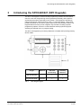
SPCK420/421
LCD-Keypad for
SPC4000/5000/6000
User Manual
Building Technologies
Fire Safety & Security Products
Data and design subject to change without notice. / Supply subject to availability.
© 2008 Copyright by
Siemens Building Technologies
We reserve all rights in this document and in the subject thereof. By acceptance of the document the recipient acknowledges these rights
and undertakes not to publish the document nor the subject thereof in full or in part, nor to make them available to any third party without our
prior express written authorization, nor to use it for any purpose other than for which it was delivered to him.
Contents
1
1.1
1.2
1.2.1
1.2.2
1.3
1.4
Security ....................................................................................................5
Target group..............................................................................................5
General safety instructions .......................................................................5
General information...................................................................................5
Operation ..................................................................................................5
Meaning of the written warning notices ....................................................5
Meanings of the hazard symbols ..............................................................5
2
2.1
Directives and Standards.......................................................................6
EU Directives ............................................................................................6
3
Introducing the SPCK420/421 (SPC Keypads).....................................7
4
Using the Keypad Interface....................................................................9
5
5.1
5.2
5.3
5.4
5.5
5.6
5.7
5.8
5.9
5.10
5.11
Setting, Unsetting, and Restoring the System...................................11
Setting the System: FULLSET ................................................................11
Setting the System: PARTSET A............................................................12
Setting the System: PARTSET B............................................................12
Failing to Set the System ........................................................................12
Force Setting the System........................................................................13
Unsetting the System ..............................................................................13
Restoring an Alarm Activation (Alert)......................................................14
Coded Restore ........................................................................................15
Using 868MHz Wireless Fob* .................................................................15
Using a Portable ACE .............................................................................16
Using X10 Features ................................................................................16
6
6.1
6.2
6.3
6.4
6.5
6.6
6.7
6.8
6.9
6.10
User Menu Options ...............................................................................17
Inhibiting a Zone......................................................................................17
Isolating a Zone or Fault .........................................................................18
Set Date/Time .........................................................................................18
Perform Tests..........................................................................................19
Viewing the Event Log ............................................................................19
Enabling the Chime Function..................................................................19
Creating System Users ...........................................................................20
Changing a User Code ...........................................................................20
SMS ........................................................................................................21
Allowing Engineer/Manufacturer Access ................................................21
7
7.1
7.2
7.3
Appendix................................................................................................22
Appendix A: Standard User Settings ......................................................22
Appendix B: User Configuration and Test Options .................................23
Appendix C: Zone Chart .........................................................................24
3
Siemens Building Technologies
Fire Safety & Security Products
09.2008
4
Siemens Building Technologies
Fire Safety & Security Products
09.2008
Security
1
Security
1.1
Target group
The instructions in this documentation are directed at the following target group:
Target readers
Qualification
End user
Instruction by technical Performs only the
specialists is necessary. procedures for proper
operation of the
product.
1.2
General safety instructions
1.2.1
General information
Activity
Condition of the
product
The product is installed
and configured.
– Read the general safety precautions before operating the unit.
1.2.2
Operation
Dangerous situation due to false alarm
– Make sure to notify all relevant parties and authorities providing assistance
before testing the system.
– To avoid panic, always inform all those present before testing any alarm
devices.
1.3
1.4
Meaning of the written warning notices
Signal Word
Type of Risk
DANGER
Danger of death or severe bodily harm.
WARNING
Possible danger of death or severe bodily harm.
CAUTION
Danger of minor bodily injury or property damage
IMPORTANT
Danger of malfunctions
Meanings of the hazard symbols
WARNING
Warning of a hazard area
WARNING
Warning of dangerous electrical voltage
5
Siemens Building Technologies
Fire Safety & Security Products
09.2008
Directives and Standards
2
Directives and Standards
2.1
EU Directives
This product complies with the requirements of the European Directives
2004/108/EC“Directive of Electromagnetic Compatibility” and 2006/95/EC “Low
Voltage Directive”. The EU declaration of conformity is available to the responsible
agencies at:
Siemens Building Technologies
Fire & Security Products GmbH & Co. oHG
76181 Karlsruhe
European Directive 2004/108/EC „Electromagnetic Compatibility”
Compliance with the European Directive 2004/108/EC has been proven by testing
according to the following standards:
emc emission
EN 55022 Class B
emc immunity
EN 50130-4
European Directive 2006/95/EC „Low-Voltage Directive”
Compliance with the European Directive 2006/95/EC has been proven by testing
according to the following standard:
Safety:
EN 60950-1
6
Siemens Building Technologies
Fire Safety & Security Products
09.2008
Introducing the SPCK420/421 (SPC Keypads)
3
Introducing the SPCK420/421 (SPC Keypads)
The SPC LCD Keypad is a wall-mounted programming interface unit that allows
users to enter User Programming menus (password protected), and to perform
operational procedures (set/unset) on the system. The Keypad unit includes an
integral front tamper switch and has a 2 line x 16 character display. Three LEDs
provide information on AC power, system alerts, and communications status. The
Keypad features an easy-to-use navigation key to assist in locating required
programming options, and has 2 context sensitive soft keys (left and right) for
selecting the required menu or program setting.
The SPC LCD Keypad may be factory fitted with a Portable ACE (PACE) proximity
device reader.
K-Type
Standard Keypad
Keypad with PACE
Tab. 1
Model no.
SPCK420
SPCK421
Standard
Functionality
Proximity
Detection
9
8
9
9
SPC Keypad Types
7
Siemens Building Technologies
Fire Safety & Security Products
09.2008
Introducing the SPCK420/421 (SPC Keypads)
1
Programming Keys:
1 x multi-functional navigation key
2 x context sensitive programming keys (left and right)
2
Portable ACE Receiver Area
3
LED (Status Indicator see Tab. 2)
4
Keypad:
12 x alphanumeric keys for numeric and text data entry
5
Pull-down Information Tab:
The installer contact and licence details are located on the pull down information tab at the
rear of the unit
Fig. 1
SPC LCD Keypad
LED
AC Mains LED
(Green)
Description
Indicates presence or failure of the Mains supply
FLASHING: AC Mains fault detected
STEADY: AC Mains OK
Indicates a system alert
System Alert
(Yellow)
FLASHING: System Alert detected; display indicates the
location and nature of the alert. If the system is SET, no
indication of system alerts is given.
OFF: No alert detected
Comms LED
(Red)
Tab. 2
Indicates status of the X-BUS communications when in
FULL ENGINEER programming
LED Status Indicators
8
Siemens Building Technologies
Fire Safety & Security Products
09.2008
Using the Keypad Interface
4
Using the Keypad Interface
Fig. 2
1.
Basic Keypad Programming Interface
Top Line of Display
In the normal state, this line displays the current date and time.
In Programming Mode, this line displays one of the following:
– The programming feature to be selected
– The current setting of the selected feature
During an alert condition, this line displays the nature of the current alert.
2.
Bottom Line of Display
In the normal state, this line is blank.
In Programming Mode, this line displays options available to the
user/Engineer. These options are aligned over the left and right soft keys for
selection as required.
3.
Left Soft Key
This key is used to select the option presented on the left side of the bottom
line of the display. Possible values are:
– EXIT to exit programming
– BACK to return to previous menu
4.
Right Soft Key
This key is used to select the option presented on the right side of the bottom
line of the display. Possible values are:
– SELECT to select the option displayed on the top line
– ENTER to enter the data displayed on the top line
– SAVE to save a setting
5.
Multi-Function Navigation Key (Navi-Key)
9
Siemens Building Technologies
Fire Safety & Security Products
09.2008
Using the Keypad Interface
OK
The OK button acts as a SELECT key for the menu option
displayed on the top line and also as an ENTER/SAVE key for data
displayed on the top line.
In Programming Mode, the right arrow key advances the user
through the menus in the same way as pressing the SELECT option
(right soft key). When no more menu options can be selected, this
key has no function. In data entry mode, this key advances the
cursor one position to the right.
In Programming Mode, the left arrow key returns the user to the
previous menu level. Pressing this key while in the top menu level
exits the user from programming. In data entry mode, this key
moves the cursor one position to the left.
In Programming Mode, the up arrow key moves the user to the
previous programming option in the same menu level. Continually
pressing this key scrolls through all the programming options
available on the current menu level. In alphanumeric mode,
pressing this key over a lower case character changes the
character to upper case.
In Programming Mode, the down arrow key moves the user to the
next programming option in the same menu level. Continually
pressing this key scrolls through all of the programming options
available on the current menu level. In alphanumeric mode,
pressing this key over an upper case character changes the
character to lower case.
10
Siemens Building Technologies
Fire Safety & Security Products
09.2008
Setting, Unsetting, and Restoring the System
5
Setting, Unsetting, and Restoring the System
The following functions are available to users by
entering using just their user code; these functions
do not require menu navigation on the Keypad.
User codes can be 4, 5, or 6 digits, depending
upon the Grade the system has been programmed
to.
A user’s ability to see menus and options available
on the intrusion pontrol panel is programmed by
the installation engineer. If users cannot see an
option described in this manual, they do not have
rights to access that functionality.
When the user code is entered, the digits are
displayed as asterixes on the display and the left
function key displays the QUIT option. This is for
security reasons, so codes are not visible when
entered.
...FULLSET?...
EXIT
SELECT
... PARTSET A?...
EXIT
SELECT
...PARTSET B?...
EXIT
SELECT
...MENUS...
EXIT
SELECT
After entering the user code, the following options
are presented: FULLSET, PARTSET A, PARTSET B, MENUS. Scroll through
these options by using the up/down arrow keys.
5.1
Setting the System: FULLSET
The FULLSET option provides the following functionality:
z Full protection to a building (opening of alarm
zones activates alarm)
z Opening of entry/exit zones starts the entry
timer. If the alarm is not unset before the entry
timer expires, the alarm is activated
To select the FULLSET option, enter a valid user
code, and press SELECT (right soft key). The
second line of the display counts down the exit
timer and the buzzer sounds to indicate that the
user should exit the building. When the system
has been fully set, the LCD displays FULLSET on
the bottom line for approximately 10 seconds.
…FULLSET?...
EXIT
SELECT
18/06/2008 12:30
SETTING 45 SECONDS
18/06/2008 12:30
SYSTEM FULLSET
If the alarm fails to set, see Section 5.4
11
Siemens Building Technologies
Fire Safety & Security Products
09.2008
Setting, Unsetting, and Restoring the System
5.2
Setting the System: PARTSET A
The PARTSET A option provides the following functionality:
z Perimeter protection to a building while
allowing free movement through the exit and
access areas.
…PARTSET A?...
EXIT
SELECT
z Exclusion of EXCLUDE A zones from
protection
z Instant activation of alarm on selection of
mode; by default there are no exit times
associated with PARTSET A
18/06/2008 12:30
PARTSET A SET
To select PARTSET A, enter a valid user code, scroll to the PARTSET A option
and press SELECT (right soft key).
If the alarm fails to set, see Section 5.4.
5.3
Setting the System: PARTSET B
The PARTSET B option provides the following functionality:
z Perimeter protection to a building while
allowing free movement through the exit and
access areas.
…PARTSET B?...
EXIT
SELECT
z Exclusion of EXCLUDE B zones from
protection
z Instant activation of alarm on selection of
mode; by default there are no exit times
associated with PARTSET B
18/06/2008 12:30
PARTSET B SET
To select PARTSET B, enter a valid user code, scroll to the PARTSET B option
and press SELECT (right soft key).
If the alarm fails to set, see section 5.4.
NOTE
Partset A and Partset B configuration modes are dependent upon the system has been programmed.
5.4
Failing to Set the System
The system fails to set if there is an open or fault condition detected on an alarm
zone when the FULLSET or PARTSET A/B option is selected. The Keypad
displays the zone number and description.
To set the system, locate the zone and close or fix the fault. Repeat the FULLSET
or PARTSET A/B operation.
12
Siemens Building Technologies
Fire Safety & Security Products
09.2008
Setting, Unsetting, and Restoring the System
5.5
Force Setting the System
The system can be forced to set while an alarm
zone is still open. This operation inhibits the open
zone and sets the system as normal.
If a user has the right to FORCE SET the system
and an alarm zone is open, when the FULLSET or
PARTSET option is selected, the Keypad buzzer
beeps and the first line of the display indicates the
open zone. The user is presented with the options
to QUIT (left soft key) or FORCE (right soft key).
QUIT: Selecting this option aborts the attempt to
set the system and returns the user to User
Programming.
FORCE: Selecting this option inhibits the open
zone and forces the system to set.
5.6
ZONE 1
QUIT
OPEN
FORCE
…FORCED SET?...
BACK
SELECT
18/06/2008 12:30
SETTING 45 SECONDS
10/06/2008 12:30
SYSTEM FULLSET
Unsetting the System
To UNSET a system:
1.
Enter a valid user code. The Keypad displays
a prompt to unset the system.
2.
To UNSET the system, press SELECT (right
soft key). The Keypad display indicates that
the system is unset on the bottom line of the
display for approximately 5 seconds. After this
time has elapsed, the bottom line is cleared.
3.
If the alarm has been activated, entering the
user code silences all bells and strobes and
the message PANEL DISARMED is displayed
on the Keypad for approximately 5 seconds.
4.
The source of the alarm condition is displayed
on the Keypad and the Alert LED flashes. The
Keypad continues to display the alert until the
alert is restored.
...UNSET?...
EXIT
SELECT
SYSTEM UNSET
PANEL DISARMED
ALARM ZONE 2
FIRST ZONE
13
Siemens Building Technologies
Fire Safety & Security Products
09.2008
Setting, Unsetting, and Restoring the System
5.7
Restoring an Alarm Activation (Alert)
Alert conditions on the intrusion control system are indicated on the Keypad by a
flashing yellow Alert LED and by activation of the buzzer. The Keypad indicates the
location and nature of the alert condition. The ability of a user to restore alerts
depends on the security grade setting of the system (in accordance with standards
[1]). An alert condition can only be restored once the fault or zone that caused the
alert has been physically reset to its normal operating state; e.g. an open zone has
been closed again or a severed X-BUS connection re-established.
Users may be restricted from using the Restore feature if an Engineer chooses not
to select ‘Restore’ within the User Rights menu for select users. Users who cannot
restore an alert receive fault messages on the Keypad until the zone or fault
condition is either inhibited or isolated.
Alarm conditions on the SPC system are indicated on the Keypad by a flashing
yellow Alert LED (see Section Fehler! Verweisquelle konnte nicht gefunden
werden., Using the Keypad) and by activation of the buzzer. The Keypad displays
the location and nature of the alert
condition.
To restore an alert condition triggered by a
zone opening:
1.
Locate the open zone (displays on
the Keypad) and restore the alarm
sensor to its normal state by closing
the door or window.
2.
Enter a valid user code and select the
RESTORE option (right soft key). The
zone causing the alert displays on the
top line.
3.
Press the right menu key to restore
the alert. The message ALL ALERTS
RESTORED displays and the
flashing Alert LED turns off.
ALARM ZONE 2
Sitting Room
Sitting Room
QUIT
RESTORE
ALL ALERTS
RESTORED
For system or communications type alert
conditions (Mains failure or X-BUS disconnect), locate the source of the alert
condition and check that all wires and cables are properly connected.
For a tamper alert, ensure the lids on all enclosures and devices are correctly
closed. If the physical fault cannot be restored to its normal operating state, contact
the installation engineer. The alarm system still operates by either inhibiting or
isolating the fault condition.
NOTE
An Alert condition only displays on the Keypad when the system is UNSET. If the system is SET when
an alert condition occurs, the Keypad gives no indication of that alert condition until such time as the
system is UNSET.
14
Siemens Building Technologies
Fire Safety & Security Products
09.2008
Setting, Unsetting, and Restoring the System
5.8
Coded Restore
The coded restore option is only available if the Security Grade of the system is set
to Grade 3 or Engineer Configure. It provides the user with the ability to restore
alert conditions that would normally only be available to the installation engineer.
To provide the user with this ability, it is necessary to protect this feature with a
code.
To perform a coded restore on the system:
1.
Ensure that the zone or fault that caused the alert condition has been
physically restored to its normal operating state.
2.
Contact the installer or the alarm receiving centre (ARC) before entering user
programming and selecting the coded restore feature in the menus option.
(Contact details should be available from the drop down label beneath the
Keypad.)
3.
Press SELECT on the Coded Restore option. A 6-digit reset code displays on
the top line.
4.
Provide 6-digit code to installer/ARC.
5.
Receive newly generated code from installer/ARC.
6.
Enter new code at the AUTH CODE prompt.
7.
Press SELECT.
Î
The message SYSTEM RESTORED displays on the top line of the display.
NOTE
The coded restore feature can only be operated from the Keypad. This feature is not accessible from
the SPC5000/6000 web server browser.
5.9
Using 868MHz Wireless Fob*
*NOTE: Wireless features and devices will be available with a later market
package.
15
Siemens Building Technologies
Fire Safety & Security Products
09.2008
Setting, Unsetting, and Restoring the System
5.10
Using a Portable ACE
If a PACE reader is installed and configured on the SPC Keypad, it is functional
only with users of PACE-configured profiles.
If a Limited User’s profile is configured for such device and functionality, once
presented within 1cm of the Keypad’s receiver area, the PACE enables setting and
unsetting denoted by the usual set/unset beeps.
If Manager and/or Standard Users’ profiles are configured for such device and
functionality, access to keypad is allowed using the PACE. Presentation of the
device within 1cm of the Keypad’s receiver area logs in the user and prompts
menu options.
For additional security measures, engineers have the option to set the PACE
configurations to PIN and PACE. This prompts and requires user code following
presentation of the PACE.
5.11
Using X10 Features
X10 is a technology that allows peripheral devices, such as lights, heaters, or
appliances, to be controlled by the system and system events can be used to
trigger outputs on the X10 devices. For example, a hall light could be configured to
turn on when the front door of the house is opened. Alternatively, the function can
be controlled directly at the Keypad.
X10 settings are programmed by the installation engineer and users are informed
of the settings and the corresponding keys on the Keypad that the settings are
assigned to.
To turn an X10 feature on, press the hash (#) key and the feature number. The
corresponding device turns on. To turn an X10 feature off, repeat the same
keystrokes. The corresponding device turns off. The installation engineer can fill in
the following table for quick reference.
Code #
Description
#0
#1
#2
#3
#4
#5
#6
#7
#8
#9
Tab. 3
X10 Codes and Descriptions
NOTE
X10 uses uni-directional communication and should not be used for critical devices because system
interference can prevent the device from responding to the command.
16
Siemens Building Technologies
Fire Safety & Security Products
09.2008
User Menu Options
6
User Menu Options
The following functions are available to users under MENUS on the Keypad.
In navigation mode following input of user code, the user selects one of a number
of pre-defined programming options from a list. Pressing the up/down arrow keys
scrolls the list of options available for selection. An ellipsis (…) on accompanying
graphics denotes when there is a choice of menu selection by scrolling.
6.1
Inhibiting a Zone
Zones on the system can be manually inhibited
from the Keypad. Inhibiting a zone removes that
zone from the system, silently disregarded, for
one alarm set period only.
1.
Press SELECT the INHIBIT option on the
Keypad.
2.
Scroll to the ZONES option and press
SELECT (right soft key).
3.
Scroll and select the required zone and
toggle the setting from NOT INHIBITED to
INHIBITED using the up/down arrow keys.
4.
Press SELECT (right soft key) to exit user
programming.
…INHIBIT…
EXIT
SELECT
…ZONES…
BACK
SELECT
…ZONE1…
BACK
SELECT
…INHIBITED…
BACK
SELECT
NOTE
Only the Alarm, Exit/Entry, Fire Exit and Line Zone types can be inhibited on the SPC system. All
other zone types are not displayed in the inhibit menus.
17
Siemens Building Technologies
Fire Safety & Security Products
09.2008
User Menu Options
6.2
Isolating a Zone or Fault
Zones or faults on the system can be manually
isolated from the Keypad. Isolation allows a zone
to be removed from the system, silently
disregarded, until it is set for de-isolation by the
user.
To isolate a zone:
1.
Scroll to the ISOLATE option and press
SELECT (right soft key).
2.
Scroll to the ZONES option and press
SELECT (right soft key).
3.
4.
6.3
A list of zones on the system displays. Select
the required zone and toggle the setting from
NOT ISOLATED to ISOLATED using the
up/down arrow keys.
...ISOLATE...
EXIT
SELECT
... ZONES...
BACK
SELECT
... ZONE1...
BACK
SELECT
...ISOLATED...
BACK
SELECT
Press SELECT (right soft key) to exit User
Programming.
Set Date/Time
The date and time can be manually entered on the system. The time and date
information displays on the Keypad to be used with time-related programming
features.
To program the Date and Time:
1.
Scroll to the SET DATE/TIME option and
press SELECT (right soft key). The date
displays on the top line.
2.
To enter a new date, press the required
numeric keys. To move the cursor to the left
and right, press the left and right arrow keys.
Press ENTER (right soft key) to save the
new date.
3.
To enter a new time, press the required
numeric keys. To move the cursor to the left
and right, press the left and right arrow keys. Press ENTER (right soft key) to
save the new time.
...SET DATE/TIME...
EXIT
SELECT
DATE
BACK
08/07/2008
ENTER
UPDATED
18
Siemens Building Technologies
Fire Safety & Security Products
09.2008
User Menu Options
6.4
Perform Tests
Tests can be performed on the system to determine if bells, buzzers, and other
audible devices operate correctly.
To perform a test on the system:
1.
Scroll to the TEST option and press SELECT
(right soft key).
2.
Scroll and select BELL TEST, WALK TEST,
or AUDIBLE OPTIONS.
3.
When BELL TEST is selected, users may test
each device by pressing NEXT for external
bells, strobe, internal bells, or buzzer. The
device sounds for each to verify it is operating
correctly.
4.
6.5
...TEST...
EXIT
SELECT
...BELL TEST...
BACK
SELECT
EXT BELL
BACK
NEXT
When WALK TEST is selected, users can test
the operation of each alarm device by
activating the device and listening for audible beeps at the Keypad.
Viewing the Event Log
The most recent events on the system can be viewed by selecting the EVENT
LOG option. The most recent events display on the bottom line with previous
events displaying for one second in turn.
To view the event log on the Keypad:
1.
Scroll to the EVENT LOG option and press
SELECT (right soft key).
Î
2.
6.6
The Keypad displays the recent events on the
system on the bottom line display for one
second in turn.
To view an event from a particular date, enter
the date with the numeric keys.
...EVENT LOG...
EXIT
SELECT
21 Apr 08
12:30
WALKTEST BY USER
DATE
BACK
18/04/2008
ENTER
Enabling the Chime Function
The chime function can be enabled or disabled on all zones where the chime has
been programmed as an audible alert feature.
To enable or disable the chime function:
1.
Scroll to the CHIME option and press
SELECT (right soft key).
2.
Toggle between enable or disable for the
chime function.
...CHIME...
EXIT
SELECT
...ENABLED...
BACK
SELECT
19
Siemens Building Technologies
Fire Safety & Security Products
09.2008
User Menu Options
6.7
Creating System Users
In order to create a user for the system, the creator must be a Manager user type.
To create a user:
1.
Scroll to the USERS option and press
SELECT.
2.
Scroll to ADD and press SELECT.
Î
3.
Press SELECT for the default name and
number, or enter a customized user name and
press SELECT.
4.
There are three types of users available:
STANDARD USER, LIMITED USER, or
MANAGER. Scroll to the preferred type and
press SELECT. Note: user profiles may be
changed at any time.
Î
5.
The system generates a default code for each
new user. To change this code, overwrite the
digits shown in the initial digits field.
Press SELECT to accept or enter a new user
code and press SELECT.
Î
6.8
The system generates and displays next
available user name.
...USERS...
EXIT
SELECT
...ADD...
BACK
SELECT
...USER1...
BACK
SELECT
...STANDARD USER...
BACK
SELECT
CODE 1234
ENTER
BACK
USER1 CREATED
The Keypad confirms that the new user has been created.
Changing a User Code
If users have the right to change their user code, this can be done through the
Keypad.
Note, if the system is set for 5-digit user codes, a new 5-digit code must be
entered. The system will not accept a code with fewer numbers than it is set to
receive.
To change a user code:
1.
Scroll to CHANGE CODE and press
SELECT (right soft key).
Î
...CHANGE CODE...
EXIT
SELECT
A randomly generated user code appears.
2.
Select new code, if acceptable. Or overwrite
by entering the new user code and press
ENTER (right soft key).
CODE
BACK
3.
Confirm the new code, press SAVE (right soft
key).
UPDATED
4.
Press BACK (left soft key) to return to the
previous screen to amend the code.
Î
4740
SELECT
During the process if the display times out, the old code remains valid.
NOTE
Where User Duress feature is enabled, consecutive user codes (i.e. 2906, 2907) are not permitted, as
entering this code from the Keypad would activate a user duress event.
20
Siemens Building Technologies
Fire Safety & Security Products
09.2008
User Menu Options
6.9
SMS
The SPC systems support SMS communication from the panel to selected users’
mobile phones as well as users being able to control the SPC remotely via SMS.
These two features work hand in hand as it allows the user to take action using the
SMS control after a SMS notification without the need to be physically at the
premises.
The SMS notification can be set up to send a range of events that occur on the
system such as: Alarms / Confirmed Alarms / Faults / Tampers / Setting / Unsetting
/ Inhibits / Isolates etc. This can provide the user a confirmation of the status of the
panel at their premises.
The SMS control can be set up so that a remote user can send a SMS message to
perform the following actions at the panel: Set / Unset / Enable Engineer / Disable
Engineer / Enable Manufacturer access / Disable Manufacturer access / Outputs
on / Outputs off. (Manufacturer Access is only available in SPC5000/6000.)
The SMS notification can operate with a PSTN modem if the PSTN operator
supports SMS over PSTN where as SMS control will need a GSM modem at the
panel. Please Note: A GSM modem will support both SMS notification and control.
6.10
Allowing Engineer/Manufacturer Access
When engineer or manufacturer access has been
allowed, the Keypad displays the text ENGINEER
ENABLE or MANUFACT ENABLE. Once access
has been granted, the user cannot access the
system until the engineer has logged off.
To allow engineer access:
1.
2.
Scroll to the GRANT ACCESS option and
press SELECT (right soft key).
Select the ALLOW ENGINEER option (right
soft key) and select ENABLED.
To disallow engineer/manufacturer access, follow
the same path and toggle to DISABLED and press
SELECT (right soft key).
...GRANT ACCESS...
EXIT
SELECT
...ENABLE...
SELECT
EXIT
...ALLOW ENGINEER...
EXIT
SELECT
UPDATED
EXIT
SELECT
NOTE
SPC4000 provides only Engineer Access. Menu options on the SPC4000 display allowing and
disallowing Engineer Access only.
21
Siemens Building Technologies
Fire Safety & Security Products
09.2008
Appendix
7
Appendix
7.1
Appendix A: Standard User Settings
The operational features of the SPC systems are described below. The installation
engineer will inform users rights assigned to each user profile. Depending on how
the system has been programmed, users may have rights to all or some of these
features.
Operation
User Profile
Default
Description
FULLSET
Limited
Standard
Manager
The FULLSET operation fully sets the alarm system and provides full protection
to a building (opening of any alarm zones activates the alarm).
On selecting FULLSET, the buzzer sounds and the Keypad display counts down
the exit time period. Exit the building before this time period has expired.
When the exit time period has expired, the system is set and opening of
entry/exit zones starts the entry timer. If the system is not Unset before the entry
timer expires, the alarm is activated.
To perform a FULLSET, see 5.1.
PARTSET A
Standard
Manager
The PARTSET A option provides perimeter protection to a building while
allowing free movement through the exit and access areas.
Zones that have been classified as EXCLUDE A remain unprotected in this
mode. By default, there is no exit time; the system sets instantly on selection of
this mode. An exit timer can be applied to this mode by enabling the Partset A
timed variable.
To perform a PARTSET A, see Section 5.2.
PARTSET B
Standard
Manager
The PARTSET B option applies protection to all zones except those that have
been classified as EXCLUDE B.
By default there is no exit time; the system sets instantly on selection of this
mode. An exit timer can be applied to this mode by enabling the Partset B timed
variable.
To perform a PARTSET B, see Section 5.3.
FORCESET
Standard
Manager
The FORCESET option is presented on the Keypad display when an attempt is
made to set the system while an alarm zone is faulty or still open (the top line of
the display shows the open zone).
Selecting this option sets the alarm and inhibits the zone for that set period.
To perform a FORCESET, see Section 5.5.
UNSET
Limited
Standard
Manager
The UNSET operation unsets the alarm. This menu option is only presented on
the Keypad after an alarm has been activated and a valid user code has been
entered.
To UNSET the system, see Section 5.6.
RESTORE
Standard
Manager
The RESTORE operation restores an alert condition on the system and clears
the alert message associated with that alert condition.
An alert condition can only be restored after the zone(s) or fault(s) that triggered
the alert condition have been restored to their normal operating state and the
RESTORE option in user programming is selected for that zone.
To RESTORE an alert, see Section 5.7.
Tab. 4 Standard User Settings
22
Siemens Building Technologies
Fire Safety & Security Products
09.2008
Appendix
7.2
Appendix B: User Configuration and Test Options
Operation
User Profile
Default
Description
ISOLATE
Manager
Isolating a zone deactivates that zone until such time as the zone is de-isolated again.
All zone types on the SPC systems can be isolated.
Use of this feature to deactivate faulty or open zones should be considered carefully;
once a zone is isolated, it is ignored by the system and could be overlooked when setting
the system in the future, compromising the security of the premises.
To isolate a zone, see Section 6.2.
INHIBIT
Standard
Manager
Inhibiting a zone deactivates that zone for one alarm set period. Only alarm, entry/exit,
fire exit and line zone types can be inhibited.
This is the preferred method of deactivating a faulty or open zone as the fault or open
condition is displayed on the Keypad each time the system is being set to remind the
user to attend to that zone.
To inhibit a zone, see Section 6.1.
CHANGE
CODE
Standard
Manager
GRANT
ACCESS
Manager
SET DATE
/ TIME
Standard
Manager
This menu option allows users to change their user codes.
To change a user code, see Section 6.8.
This option allows users to grant access to manufacturer and engineer programming.
To grant engineer access, see Section 6.10. (SPC4000 allows only Engineer Access)
Use this menu option to program the time and date on the system.
Ensure the time and date information is accurate; these fields are presented in the event
log when reporting system events.
To set the date and time, see Section 6.3.
TEST
Standard
Manager
This menu option provides the following test features:
1. Bell test: The bell test activates the external bells, strobe, internal bells, and buzzer in
turn for 5 seconds to ensure their correct operation.
2. Walk test: A walk test allows for testing of the operation of all alarm sensors on a
system. When this option is selected, the Keypad displays the number of zones to test
on the system. Activate each alarm sensor (by opening the door or window) and check
for an audible beep at the Keypad. Isolated and inhibited zones are not included in the
walk test.
3. Audible Options: This option allows users to select which devices will activate during
the walk test and which will be silent.
To perform a test, see Section 6.4.
EVENT
LOG
Standard
Manager
This menu option displays the most recent event on the Keypad display. The event log
details the time and date of each logged event.
To view the event log, see Section 6.5.
CHIME
Standard
Manager
All zones that have the CHIME attribute set generate a short burst of audible tone on the
Keypad buzzer when they are opened (while the system is unset).
This menu option allows for enabling or disabling of the chime feature on all zones.
To enable or disable the chime attribute, see Section 6.6.
SETUP
SMS
Tab. 5
Manager
This feature allows users to set up the SMS messaging service if a modem is installed
on the system.
User Configuration and Test Options
23
Siemens Building Technologies
Fire Safety & Security Products
09.2008
Appendix
7.3
Zone #
Appendix C: Zone Chart
Description
24
Siemens Building Technologies
Fire Safety & Security Products
09.2008
Issued by
Siemens Building Technologies
Fire & Security Products GmbH & Co. oHG
D-76181 Karlsruhe
www.buildingtechnologies.siemens.com/
Document no.
A6V10209178
Edition
23.09.2008
© 2008 Copyright by
Siemens Building Technologies
Data and design subject to change without notice.
Supply subject to availability.