1
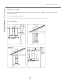
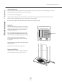
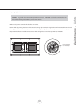
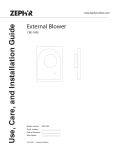
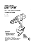
Use, Care, and Installation Guide
www.zephyronline.com
Trapeze
CTP-E 48SX
CTP-E54SX
CTP-E 60SX
Model number:
Serial number:
Date of Purchase:
Sales Dealer:
MAY07.0101 © Zephyr Corporation.
www.zephyronline.com
2
3
INSTALLATION
Ducting Calculation Sheet ...............................
Mounting Height and Clearance .....................
Ducting ..................................................................
Specifications .......................................................
Internal Blower ....................................................
Preparing Hood for External Blower ..............
Mounting the Hood ............................................
4
5
6
7
8-9
10
11 - 14
FEATURES & CONTROLS
Controls Overview .............................................. 15 - 16
MAINTENANCE
Cleaning ................................................................. 17
Lights ....................................................................... 18
TROUBLE SHOOTING ...................................... 19
LIST OF ACCESSORIES/PARTS ....................... 20
1
Table of Contents
SAFETY NOTICE ..............................................
LIST OF MATERIALS .......................................
www.zephyronline.com
Important safety Notice
READ AND SAVE THESE INSTRUCTIONS
WARNING
TO REDUCE TH E R IS K O F FIR E O R E LE C TR IC SHOC K, DO NOT USE TH IS FAN W ITH ANY S O LID-S TATE
SPE E D CONTROL DEV IC E.
WARNING
TO RE DUCE TH E R IS K O F FIR E, E LE C TR IC SH O C K, O R INJU RY TO P E R SON S, O B S E RVE TH E FO LLO W ING:
a. Use this unit only in the manner intended by the manufacturer, If you have questions, contact the manufacturer.
b. Before servicing or cleaning unit, switch power off at service panel and lock the service disconnecting means to prevent power from being
switched on accidentally.
When the service disconnecting means cannot be locked, securely fasten a prominentwarning device, such as tag, to the service panel.
CAUTION
For General VentilatingUse Only. Do not Use to Exhaust Hazardous or Explosive Materials and Vapors.
Take care when using cleaning agents or detergents.Suitable for use in household cooking area.
WARNING
TO REDUC E TH E R IS K O F A RA NG E TO P GR E AS E FIR E:
a. Never leave surface units unattendedat high settings. Boilovers cause smoking and greasy spillovers that may ignite. Heat oils slowly on low
or mediumsettings.
b. Always turn hood ON when cooking at high heat or when cooking flambeing food (i.e. Crepes Suzette, Cherries Jubilee, Peppercorn
Beef Flambe)
c. Clean ventilating fans frequently. Grease should not be allowed to accumulate on fan or filter.
d. Use proper pan size. Always use cookware appropriatefor the size of the surface element.
WARNING
TO RE DUC E TH E R IS K O F INJURY TO P ERSON S IN TH E EV E NT O F A RA NG E TO P G R E AS E FIR E, O B S E RVE TH E FO LLOW ING :
a. SM OTHER FLA MES with a close-fitting lid, cookie sheet, or metal tray, then turn off the burner. B E CARE FUL TO P R EV E NT BUR NS.
If the flames do not go out immediately,E VAC UATE AND CALL TH E FIR E DE PARTME NT.
b. NEV E R PIC K UP A FLAMI NG PAN - You may be burned.
c. DO NOT US E WATE R, includingwet dishcloths or towels - a violentsteam explosion will result.
d. Use an extinguisher ONLY if:
1. You know you have a class AB C extinguisher, and you already know how to operate it.
2. The fire is small and contained in the area where it started.
3. The fire departmentis being called.
4. You can fight the fire with your back to an exit.
5. Based on “Kitchen Fire Sa fety Tips” published by NFPA.
WARNING
TO R E DUC E TH E R IS K O F FIR E, E LE C TR IC SHOC K O R INJURY TO PER SONS, O B S E RVE TH E FO LLOW ING :
a. Installation Work and Electrical Wiring Must be Done by Qualified Person (s) In Accordance with all Applicable Codes and Standards,
Including Fire-Rated Construction.
b. Sufficient air is needed for proper combustion and exhausting of gases through the flue (chimney) of fuel burningequipmentto prevent back
drafting. Follow the heating equipmentmanufacturer’s guideline and safety standards such as those published by the National Fire Protection
Association (NFPA), and the American S ociety for Heating, Refrigeration, and Air ConditioningEngineers (AS H R AE) and the local code authorities.
c. When cutting or drillinginto wall or ceiling, do not damage electrical wiring and other hidden utilities.
d. Ducted fans must always vent to the outdoors.
WARNING
TO REDUC E TH E R IS K O F FIR E, US E O NLY ME TAL DU C TW O R K.
CAUTION
To reduce risk of fire and to properly exhaust air, be sure to duct air outside - Do not vent exhaust air into spaces within walls or ceilings or into
attics, crawl spaces or garages.
CAUTION
To Reduce the Risk of Fire and Electric Shock, Install This Range Hood Only with Remote Blower Models C B E-1000 Rated
Maximum 6.2 amp, 120 Vac 60Hz or Integral Blowers Manufactured by Zephyr Ventilation, Models C B I-600.
2
1
2
4
2
2
4
4
4
1
1
1
-
Lis t of M a teria ls
MODEL: CTP-ExxS
Hood
Baffle Filters
G U-10, 120V 50 W, halogen bulbs
Utensil Rails
Telescopic Duct Covers
Telescopic Rods Sets
Angle Bra ckets (27 3/8”)
Angle Bra ckets (35 3/8”)
Ceiling MountingBra cket
Internal Flange
Motor Housing
1 - HARDWARE PACKET
4 - Couplers
4 - Anchors
4 - 2” Wood Screws
4 - 2 1/2” Wood Screws
4 - 1/2” Washers
26 - 1/2” Self Tapping Screws
4 - 1/2” Screws 5x15mm
4 - 5mm Internal Diameter Washers
4 - Adhesive Fasteners
4 - Cable Ties
1 - SMALL HARDWARE PACKET
10 - Short Set Screws
12 - Medium Set Screws
1 - Tool
1 - HARDWARE PACKET FOR ELECTRICAL CONNECTION AND EXTERNAL BLOWER CONNECTION
1
1
1
12
1
12
-
External Flange with Attached 8” Collar
Junction Box with Wires
External Blower Wiring B ox with Wires
1/2” Self Tapping Screws
Electrical Connection Wiring
4mm Internal Diameter Washers
NO DUCTING IS PROVIDED
EXTERNAL AND INTERNAL BLOWER SOLD SEPARATELY
Make sure to remove the protective film off of the hood before installation in order to make removal of the film
easier. Be careful not to scratc h the stainless steel while installing.
3
Ins ta lla tion - Ductwork C a lcula tion S heet
www.zephyronline.com
Equivalent number
length x used =
Duct pieces
Equivalent number
length x used =
Duct pieces
Total
Total
3 1/4” x 10”
Rect.,
straight
1 Ft.
x(
) =
Ft.
6” Round
30 Ft.
wall cap
with damper
x(
) =
Ft.
7” Round,
straight
1 Ft.
x(
) =
Ft.
6” Round,
roof cap
30 Ft.
x(
) =
Ft.
7” Round,
straight
1 Ft.
x(
) =
Ft.
6” round to
3 1/4” x 10”
rect.
transition
1 Ft.
x(
) =
Ft.
3 1/4” x 10”
Rect. 90 0
elbow
15 Ft.
x(
) =
Ft.
16 Ft.
x(
) =
Ft.
3 1/4” x 10”
Rect. 45 0
elbow
9 Ft.
x(
) =
Ft.
6” round to
3 1/4” x 10”
rect.
transition
90 0 elbow
7” Round,
90 0 elbow
15 Ft.
x(
) =
Ft.
3 1/ 4” x 10”
Rect. 90 0
flat elbow
24 Ft.
7” Round,
45 0 elbow
9 Ft.
x(
) =
Ft.
7” Round
30 Ft.
wall cap
with damper
x(
) =
Ft.
7” Round,
roof cap
30 Ft.
x(
) =
Ft.
7” round to
3 1/4” x 10”
rect.
transition
8 Ft.
x(
) =
Ft.
7” round to
3 1/4” x 10”
rect.
transition
90 0 elbow
15 Ft.
x(
) =
Ft.
x(
) =
Ft.
Ft.
3 1/4” x 10”
30 Ft.
Rect.
wall cap
with damper
x(
3 1/4” x 10”
Rect. to
6” round
transition
5 Ft.
x(
) =
Ft.
3 1/ 4” x 10”
Rect. to
6” round
transition
90 0 elbow
15 Ft.
x(
) =
Ft.
6” Round,
90 0 elbow
15 Ft.
x(
) =
Ft.
6” Round,
45 0 elbow
9 Ft.
x(
) =
Ft.
) =
Subtotal column 1 =
Ft.
Maximum Duct Length: For satisfactory air movement, the total
duct length of a 3 1/4” x 10” rectangular, 6” or 7” or 8” diameter
round duct should not exceed 100 equivalent feet.
4
Subtotal column 2 =
Ft.
Subtotal column 1 =
Ft.
Total ductwork
Ft.
=
Maximum mount height should be no higher than 36".
Min 34"-Max 52"
9"
Min 28"-Max 36"
Min 98"-Max 124”
It is importantto install the hood at the proper mounting
height. Hoods mountedtoo low could result in heat
damage and fire hazard; while hoods mountedtoo high
will be hard to reach and will loose its performance and
efficiency.
If available, also refer to range manufacturer's height
clearance requirements and recommended hood
mountingheight above range. Always check your local
codes for any differences.
*Minimum ceiling height of 98”. Hood
mounted at 28” above cooking surface.
**Maximum ceiling height of 124". Hood
mounted at 36" above cooking surface.
36"
Minimum Duct Size:
DUCTING
Round - 6” minimumat 600 cfm
Round - 10” to 8” minimum at 1000 cfm
Rect angular - 3 1/4” x 10” minimum only if
using internal blower at 600 cfm. Using
rectangular ductwork will require a transition
adapter (not provided, but readily available at
most hardware stores).
A minimumof 6” round or 3-1 /4 x 10"
rectangular duct work must be used to maintain
maximumair flow efficiency with the 600 cfm
internal blower. A minimumof 10” to 8” round must
be used with the 1000 cfm external blower.
Always use rigid type metal duct work only.
Flexible ducts could restrict air flow by up
to 50%.
DAMAGE-SHIPMENT/ INSTALLATION:
Use calculation worksheet to compute total
duct work.
• Please fully inspect unit for damage
befor e installation.
ALWAYS, when possible, reduce the number
or transitions and turns. If a reducer is used,
install a long reducer instead of a pancake
reducer. Reduce duct size as far away from
opening as possible.
• If the unit is damaged in shipment , return
the unit to the store in which it was bought
for repair or replacement.
• If the unit is damaged by the customer,
repair or replacement is the responsibility
of the customer.
If turns or transitions are required:
Install as far away from opening and as far
apart, between 2, as possible.
• If the unit is damaged by the ins taller (if
other than the customer), repair of replace
ment must be made by arrangement
between customer and installer.
5
Installation - Mounting Height & Clearance
Minimummount height between range top to hood bottom should be no less than 28".
Ins ta lla tion - Ducting
www.zephyronline.com
WARNING FIRE HAZARD
NEV E R exhaust air or terminate duct work into spaces between walls, crawl spaces, ceiling,attics or garages. All exhaust must
be ducted to the outside.
Use single wall rigid Metal ductwork only.
Fasten all connections with sheet metal screws and tape all joints w/ certified Silver Tape or DuctTape.
Some Ducting Options:
External Blower
side wall cap
w/ gravity damper
Soffit or crawl space
RoofPitch w/
Flashing& Cap
External
Blower
Soffit or crawl space
6
9“
15 3/4”
26 5/8”
11 3/4“
10“
9“
32”
10 7/16”
9 1/2”
R
Min 21” - Max 40”
7/64”
12 1/8”
13/32”
2”
48” , 54” , 59 1/8”
7
41
/8
6
21/
10
O
13
/8
”
”
4”
15/32”
2”
Installation - Specifications
32“
9“
6“
Min 34“ - Max 52”
9“
Ins ta lla tion - Interna l B lower
www.zephyronline.com
ATTENTION
The following are intructions for installing internal blower model CBI-600. For instructions on preparing for external
blower model CBE-1000 please turn to page “10”. Before installing, verify that motor spins freely.
The internal blower kit consists of the blower
and capacitor box with wiring.
1. Remove existing screws from blower
housing.
2. Att ach capacitor box to blower housing
using the removed screws.
3. Att ach motor connector to capacitor box
connector.
4. P osition internal flange over blower
housing.
5. Att ach (4) 1/2” 5x15mm screws and (4)
10mm washers to hold flange to blower
housing.
8
7. Attach grounding wires from junction box
and motor to grounding screw as shown.
8. Place blower with attached flange into
motor housing as shown on Fig-A.
9. Attach using 1/2” self tapping screws to
secure in place.
10. Att ach other end of capacitor box
connector and junction box connector to
control board box and wiring box connector
inside hood.
Continue to page “11” for hood installation instructions.
For external blower installation please refer to the manual
included with the external blower.
9
Ins ta lla tion - Interna l B lower
6. Attach junction box to internal flange using
provided 1/2” self tapping screws and 4mm
internal diameter washers.
Ins ta lla tion - P repa ring Hood for E xterna l B lower
www.zephyronline.com
ATTENTION
The following are instructions on preparing your hood for installation with external blower model CBE-1000.
For instructions on installing internal blower model CBI-600 please turn to page “8”.
The external blower kit consists of an 8”
collar, external flange and external blower
wiring box. The external blower is purchased
separately.
1. P osition and attach external blower wiring
box and junction box using provided 1/2” self
tapping screws and 4mm internal diameter
washers.
2. Attach grounding wires from external
blower wiring box and junction box to
grounding screw as shown in Fig-A.
3. Position and attach external flange to
motor housing using provided 1/2” self
tapping screws.
4. Attach junction box and external blower
wiring box connectors to control board and
wiring box connectors inside hood.
10
Continue to page “11” for hood
installation instructions.
CL
Mounting
Holes
Marking for Coupler
CL
Narrow End
Tabs
Add Blockings
Tabs
Ceiling Bracket
1. Using the cardboard template from top of box, mark the center point in between the (4) mounting holes. Determine
the location for mounting your hood, place template on ceiling and mark/drill the center point for the ceiling mounting
bracket and the foud corner holes where the telescopic rod couplers will attach to the ceiling.
2. Cut out hole for the duct work.
3. Add and secure wood blockings (minimum 2x4 studs) to ceiling joists.
4. Center, mark and fasten ceiling mounting plate onto ceiling where hood is to be hung. Make sure the tabs on the
ceiling bracket are positioned to the sides as shown in the diagram. The duct covers will attach to these tabs.
5. Attach couplers to marked corners of ceiling using the provided 2 1/2” wood screws. Make sure the narrow opening of
the coupler is facing down.
6. Position electrical wiring and duct work.
ELECTRICAL - WARNING
All Electrical work must by performed by qualified electrician or person with similar technical know how
and bac kgr ound.
For personal safety, remove house fuse or open circuit breaker before beginning installation.
Do not use extension cord or adapter plug with this appliance.
Follow National Electrical Codes or prevailing local codes and ordinances.
Electric al Supply:
This appliance requires a 120V 60Hz electrical supply., and connected to an individual, properly grounded branch circuit,
protected by a 15 or 20 ampere time delay circuit breaker. Wiring must be 2 wire with ground. Please refer to label placed
on junction box.
11
Installation - Mounting the Hood
Ceiling
Ins ta lla tion - M ounting the Hood
www.zephyronline.com
1. Mount motor housing to the range hood body using (10) 1/2” self tapping screws.
2. Determine height of hood, measure and select either 27 3/8” or 35 3/8” angle brac kets and attach (4) of
them to the motor housing using (8) 1/2” self tapping screws (2) for each angle bracket.
3. Slide duct covers over motor housing. Make sure bottom duct cover with cut-out is facing the front and back of
the hood.
12
[a]
Ductwork
Electrical wiring
[b]
5. Lift assembled unit and attach all (4) angle brackets to ceiling bracket. Make sure the tabs on each angle
brackets are facing the outside. The angle brackets will fit between the slots on the ceiling bracket. One half of
the angle bracket will be on the outside of the ceiling bracket and the other half will be on the inside of the ceiling
bracket. Attach using provided1/2” self tapping screws. Re fer to diagram [a].
6. Slide duct covers up and attach duct work and electrical wiring to top of motor housing. Refer to diagram [b].
13
Ins ta lla tion - M ounting the Hood
Tab
Ins ta lla tion - M ounting the Hood
www.zephyronline.com
Telescopic Rod Installation
Set
screws
1. Install telescopic rod (thicker end down) into coupler
on top of hood and secure with medium set screw.
Attach screw using provided tool.
2. Extend telescopic rod towards the ceiling and
insert thin end of rod into ceiling coupler. Attach
a medium set screw in the middle where the
two rods attach to each other.
3. Attach medium set screw into the ceiling coupler
to secure it in place. Repeat these steps for each
telescopic rod.
Tool
Set
screw
Front
Back
Utensil Rail Installation
1. A ttach utensil rail to long side of hood canopy. A small hole has been pre-drilled into the canopy to provide a
starting point to attach the first utensil rail post. After the first post is line up with the hole, gently slide the rest
of the rail onto canopy. (note: be careful not to scratc h the stainless steel when per forming this step, this is
why there is a star ter hole).
2. A ttach a short set screw into each post in order to hold utensil rail onto canopy. Do the same for the other side.
14
Fea tures & C ontrols - Touch C ontrols & F ea tures
www.zephyronline.com
1. Blower On/Off
By pressing
, the blower is switched On and Off.
2. Speed Selection
The 3 speed levels are selected by presing
level selected.
to decrease and
to increase speed level. T
he display indicates
3. Delay Off
This is used for programmed shut down of blower and lights 15 minutes after the function is activated. Press
once,
a dot flashes in the lower right hand side of display
indicating the function is on. The hood will completely shut down
in 15 minutes.
4. Lights On/Off/Dim
Switch lights On and Off by pressing key
once. To dim lights, press
again.
5. Advance Display Functions
Filters Clean Reminder (Baffle):
After every 3 0 hours of use, the display will start flashing an
possible clogs.
reminding you to clean the baffle filters from residue and
The standard Baffle Filters are required to be cleaned frequently and as recommended in order to maintain blower
efficiency. If improperly maintained, residue from cooking will sift though filters and cause damage to hood blowers
and other sensitive components; and possibly clog duct w ork and create a fire hazard.
18
Filter Clean Reminder:
When
flashes on display, the baffle
filters installed are required to be cleaned.
This will occur after every 30 hours of use.
Clean Filters
display <A> flashes
Re-setting Function:
Reset the Filter Clean Reminder timer when
filters are cleaned and re-installed (with
hood off). Press and hold
for approx.
5 seconds, the display will appear; hold for
approximately 5 seconds until
on display disappears
. The Filter Clean
Reminder function is now re-set and a new
30 hours elapse cycle is initiated.
To Reset
hold 5 secs.
16
display from <C> to < >
F ea tures & C ontrols - B a ffle F ilters C ha nge Indica tor
Filter Clean Reminder (Standard Baffle Filters fitted):
A set of baffle filters are fitted by the factory. These Baffle Filters are intended to filter out residue from cooking. They
need not be replaced on a regular basis but are required to be kept clean. The Filter Clean Reminder function in
the microprocessor will automatically indicate by a
flashing when the metal filters need to be cleaned after
every 30 hrs. of use. Filters can be cleaned by hand with non-abrasive soap or in a dishwasher.
M a int ena nce - C le aning
www.zephyronline.com
Surface Maintenance:
Clean periodically with hot soapy water and clean cotton cloth. Do not use corrosive or abrasive detergent , or steel
wool/scouring pads which will scratch and damage surface.
For heavier soil use liquid degreaser.
After cleaning, you may use non-abrasive stainless steel polish/ cleaners, to polish and buff out the stainless luster
and grain. Always scrub lightly, with clean cotton cloth, and with the grain.
Do not use any product containing chlorine bleach. Do not use “orange” cleaners.
Baffle Filters
The Metal Filters fitted by the factory are intended
to filter out residue and grease from cooking. They
need not be replaced on a regular basis but are
requiredto be kept clean.
Filters should be cleaned after every 30 hours of
use. Use the Filter Clean Reminder function on the
controls to determine when filters require cleaning.
Handles
Remove and clean by hand or in dishwasher.
Spray degreasing detergent and leave to soak if
heavilysoiled.
Remove filters by sliding away from center of hood
and pulling down.
Dry filters and re-install before using hood.
Replacing Baffle Filters
Should filters wear out due to age and prolonged
use, contact Zephyr to purchase replacements.
17
CAUTION: Light bulbs become extremely hot when turned on. DO NOT touch bulbs until switched off
and cooled. Touching hot bulbs may cause serious burns.
Make sure all power is turned off and bulbs are not hot.
Remove bulb by pressing both ends of the metal retaining clip together, the light socket will now extend from the hood
allowing you to remove the bulb.(Be careful when releasing retaining clip as it is under pressure to hold it in place)
Replacement bulbs are available at most stores which sell light bulbs. Purchase type GU-10, 120V, 50W.
Press together
to release clip
18
M a intena nce - Lights
R eplacing Light Bulbs:
Trouble S hooting
www.zephyronline.com
Issue
Cause
What to do
After installation, the unit
doesn’t work?
1. The power source is not turned ON.
1. Make sure the circuit breaker and the unit’s
power is ON.
2. The power line and the cable locking connector is
not connecting properly.
2. Check the power connection with the unit is
connected properly.
3. The switch board and control board wirings
are disconnected.
3. Make sure the wirings between the switch
board and control board are connected properly.
4. On the switch board, Black/White wire of White
wire is disconnected.
4. Make sure the Black/White wire or White wire
connects properly.
5. The switch board or control board is defective.
5. Change the switch board or control board.
1. The motor is defective, possible seized.
1. Change the motor.
2. The thermally protected system detects if the motor
is too hot to operate and shuts the motor down.
2. The motor will function properly after the
thermally protected system cool down.
3. Damaged capacitor.
3. Change the capacitor.
1. The motor is not secure in place.
1. Tighten the motor in place.
2. Damaged blower wheel/makes noise.
2. Change the motor.
3. The hood is not secured in place.
3. Check the installation of the hood.
The motor is working,
but the lights are not.
1. Defective halogen bulb.
1. Change the halogen bulb.
2. T he light bulb is loose.
2. T ighten the light bulb.
The hood is not venting
out properly.
1. T he hood might be hanging to high from the
cook top.
1. Adjust the distance between the cook top
and the bottom of the hood within 24” and
32” range.
2. The wind from the opened windows or opened
doors in the surrounding area are affecting the
ventilation of the hood.
2. Close all the windows and doors to eliminate the
outside wind flow.
3. Blocking in the duct opening or ductwork.
3. Remove all the blocking from the duct work or
duct opening.
4. T he direction of duct opening is against the wind.
4. Adjust the duct opening direction.
5. Using the wrong size of ducting.
5. Change the ducting to at least 6” or higher
for the internal blower and 8” or higher for the
external blower.
1. Baffle filter is loose.
1. Remove filter and reinstall it or c hange the
baffle filter.
1. Control board needs to be reset.
1. Turn circuit breaker which controls the hood off
for at least 15 minutes.
Turn it back on and this should fix the problem.
1. Defective control board.
1. Replace control board.
Light works, but motor is
not turning.
The unit is vibrating.
Filter is vibrating.
After hood has been
installed for a period of
time, it stopped working.
19
www.zephyronline.com
Part Description
Part #
List of Parts and Accessories
Halogen Bulb G U-10, 120V, 50W
Z0B-0020
Accessory Description
Part #
Internal Blower, 600 cfm
CBI-600
External Blower, 1000 cfm
CBE-1000
Duct Cover Extension Kit
Z1C-00TP
20
Warranty
www.zephyronline.com
TO OBTAIN SERVICE UNDER WARRANTY
or any Service Related Questions, please call:
1-888-880-8368
Staple your receipt here.
Proof of the original purchase
date is needed to obtain service
under the warranty.
TO OBTAIN SERVICE UNDER WARRANTY: You must present proof of original purchase date.
Please keep a copy of your dated proof of purchase (sales slip) in order to obtain service under warranty.
One Year Service Repair Warranty:
For one year from date of original purchase, we will provide free of charge, service labor to repair any failed parts or
components due to manufacturing defects.
Two Years Parts Warranty:
For two years from date of original purchase, we will provide free of charge, nonconsumable replacement parts or
components that failed due to manufacturing defects. Consumable parts not covered by this warranty include: Light Bulbs,
Metal and Charcoal Filters.
Who is Covered:
This warranty is extended to the original purchaser for products purchased for ordinary home use in the 48 mainland states,
Hawaii and Washington D.C. In Canada and Alaska, this warranty is Limited.
There might be costs associated with
shipping the products to our designated service locations or you might need to pay service technician's travel costs, to have
the appliance repaired in-home.
This Warranty will be Voided when:
Product damaged through negligence, misuse, abuse, accident. Improper installation and failure to follow installation instructions. When product is used commercially or other than its intended purpose. Damaged because of improper connection with
equipment of other manufacturers. Repaired or modified by anyone other than Zephyr's Authorized Agents.
What is Not Covered:
Consumable parts such as light bulbs, filters, and fuses. Services outside of service area and the labor cost incurred in
connection with the removal, shipping and reinstallation cost, nor does it cover any other contingent expenses. The natural
wear of finish, and wear due to improper maintenance, use of corrosive and abrasive cleaning products, pads, and oven
cleaner products. Chips, dents or cracks due to abuse, misuse, freight damage, or improper installation. Service trips to your
home to teach you how to use the product. Damage of product caused by accident, fire, floods or act of God.
This warranty is valid in the United States and Canada. It is non-transferable and applies only to the original purchaser and
does not extend to subsequent owners of this product. Any applicable implied waranties, including the warranty of
merchantability, are limited in duration to a period of express warranty as provided herein beginning with the date of original
purchase at retail and, no warranties, whether express or implied, shall apply to this product thereafter.
Have your product proof of purchase with date ready for warranty issues.
Or write to:
Zephyr Corporation
Service and Warranty Department
395 Mendell Street
San Francisco, CA 94124
JAN07.0101