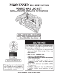
1
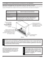
VENTED GAS LOG SET
INSTALLATION AND OPERATING INSTRUCTIONS
MODELS: VWF18 VWF24 VWF30 VWF36
Natural Gas or Propane/LPG Control Type:
Manual, Milli-Volt or Hi/Lo Remote
WARNINGS
If the information in this manual is not followed exactly,
D¿UHRUH[SORVLRQPD\UHVXOWFDXVLQJSURSHUW\GDPDJH
personal injury or loss of life.
± 'R QRW VWRUH RU XVH JDVROLQH RU RWKHU ÀDPPDEOH
vapors and liquids in the vicinity of this or any
other appliance.
$SSURYHGWR$16,=
–
WHAT TO DO IF YOU SMELL GAS
'RQRWWU\WROLJKWDQ\DSSOLDQFH
• Do not touch any electrical switch; do not use any
SKRQHLQ\RXUEXLOGLQJ
,PPHGLDWHO\ FDOO \RXU JDV VXSSOLHU IURP D
QHLJKERU
V SKRQH )ROORZ WKH JDV VXSSOLHU
V
instructions.
,I \RX FDQQRW UHDFK \RXU JDV VXSSOLHU FDOO WKH
¿UHGHSDUWPHQW
This gas log set is to be installed
RQO\LQDVROLGIXHOEXUQLQJ¿UHSODFH
ZLWK D ZRUNLQJ ÀXH FRQVWUXFWHG RI
QRQFRPEXVWLEOHPDWHULDO
± ,QVWDOODWLRQ DQG VHUYLFH PXVW EH SHUIRUPHG E\
D TXDOLILHG LQVWDOOHU VHUYLFH DJHQF\ RU WKH JDV
supplier.
READ AND SAVE THESE INSTRUCTIONS
CONTENTS
Important Safety Information ..........................3 2SHUDWLQJ,QVWUXFWLRQV ....................................42
0DQXDO&RQWURO/LJKWLQJ,QVWUXFWLRQV
3URGXFW6SHFL¿FDWLRQV.....................................4
0LOOL9ROW&RQWURO/LJKWLQJ,QVWUXFWLRQV
*HWWLQJ6WDUWHG.................................................5 Flame Appearance...........................................44
Placement in a Fireplace with a Restrictive
Fireplace Draft Test .........................................45
Barrier ..........................................................6
Remote Control Receiver Replacement ........46
Installation .........................................................7
'DPSHU6WRS,QVWDOODWLRQ7 &OHDQLQJDQG6HUYLFLQJ..................................46
%HIRUH,QVWDOOLQJWKH$SSOLDQFH7 Replacement Parts Lists ................................47
,QVWDOOLQJ9DOYH&RYHU8
$VVHPEO\
0DVVLYH2DN/RJV
:LULQJ0LOOLYROW ...............................................9
$PHULFDQ2DN/RJV
&RQQHFWLQJWKH*DV........................................10
%LUFK/RJV
0DQXDO&RQWURO 6SOLW5LYHU2DN/RJV
0LOOL9ROW&RQWURO 6SOLW3LQH/RJV
+L/R5HPRWH&RQWURO :HDWKHUHG3LQH/RJV
/RJ3ODFHPHQW ................................................12 Warranty ...........................................Back Cover
9:)0DVVLYH2DN/RJ3ODFHPHQW
9:)0DVVLYH2DN/RJ3ODFHPHQW
9:)0DVVLYH2DN/RJ3ODFHPHQW
9:)0DVVLYH2DN/RJ3ODFHPHQW
9:)$PHULFDQ2DN/RJ3ODFHPHQW
9:)$PHULFDQ2DN/RJ3ODFHPHQW
9:)$PHULFDQ2DN/RJ3ODFHPHQW
9:)%/RJ3ODFHPHQW
9:)6SOLW5LYHU2DN/RJ3ODFHPHQW
9:)6SOLW5LYHU2DN/RJ3ODFHPHQW
9:)6SOLW5LYHU2DN/RJ3ODFHPHQW
9:)6SOLW3LQH3ODFHPHQW
9:)6SOLW3LQH3ODFHPHQW
9:)6SOLW3LQH3ODFHPHQW
9:):3:HDWKHUHG3LQH/RJ
3ODFHPHQW
9:):3:HDWKHUHG3LQH/RJ
3ODFHPHQW
:):3:HDWKHUHG3,1(/2*
27D8520
IMPORTANT SAFETY INFORMATION
INSTALLER
Please leave these instructions with the owner.
OWNER
Please retain these instructions for future reference.
IMPORTANT
• Any cKDQJHWRWKLVDSSOLDQFHRULWVFRQWUROVFDQEHGDQJHURXV
,PSURSHULQVWDOODWLRQRUXVHRIWKHKHDWHUFDQFDXVHVHULRXVLQMXU\RUGHDWKIURP¿UH
EXUQVH[SORVLRQRUFDUERQPRQR[LGHSRLVRQLQJ
'RQRWDOORZIDQVWREORZGLUHFWO\LQWRWKH¿UHSODFH$YRLGDQ\GUDIWVWKDWDOWHUEXUQHU
ÀDPHSDWWHUQV
'RQRWXVHDEORZHULQVHUWKHDWH[FKDQJHULQVHUWRURWKHUDFFHVVRU\QRWDSSURYHGIRU
XVHZLWKWKLVDSSOLDQFHZKHUHDSSOLFDEOH
27D8520
are in the same room with the gas log set in operation.
'RQRWSODFHFORWKLQJRURWKHUÁDPPDEOHPDWHULDOQHDU
WKHÀUHSODFHZKHQWKHJDVORJVDUHLQXVH
12. Do not use this gas log set if any part has been underwater.
,PPHGLDWHO\FDOODTXDOLÀHGVHUYLFHWHFKQLFLDQWRLQVSHFW
the gas logs and replace any part of the control system
and any gas control which has been under water.
13. The gas log set must be isolated from the gas supply
piping system by closing its individual manual shutoff
valve during any pressure testing of the gas supply piping
system at test pressures equal to or less than 1/2 psig
(3.5kPa).
6HFXUHJDVORJVHWWRÀUHSODFH
15. This log set will burn off the paint on the front grate bar.
Note: See cleaning section for refurbishing.
16 FOR MASSACHUSETTS RESIDENTS ONLY:
WARNING
1. The installation, combustion and ventilation air must
conform with local codes or, in the absence of local
codes, with the National Fuel Gas Code, ANSI Z223.1,
or the CAN/CGA-B149 Installation code (series). This
unit complies with ANSI Z21.60-2000 decorative gas
DSSOLDQFHIRULQVWDOODWLRQLQVROLGIXHOEXUQLQJÀUHSODFH
,QVWDOODWLRQDQGUHSDLUVKRXOGEHGRQHE\DTXDOLÀHGVHUvice person. Monessen Vented Gas Logs must be installed
RQO\LQDPDVRQU\RUD8/VROLGIXHOÀUHSODFHZLWK
minimum venting requirements, see installation section.
7RSUHYHQWPDOIXQFWLRQJDVORJVHWDQGÁXHVKRXOGEH
cleaned at least annually by a professional service person.
More frequent cleaning may be required due to excessive lint from carpeting, etc. It is imperative that control
compartments, burners and circulating air passageways
be kept clean.
4. A damper clamp must be installed to provide the miniPXPSHUPDQHQWYHQWRSHQLQJWRYHQWÁXHSURGXFWV
Refer to installation instructions.
1HYHUEXUQVROLGIXHOVLQDÀUHSODFHZKHUHDJDVORJVHW
is installed.
6. This appliance must NOT be used with glass
doors in the closed position. $ ÀUHSODFH VFUHHQ
must be in place when the log set is burning. Provisions
for adequate combustion air must be provided. Adequate
FRPEXVWLRQDLUXVXDOO\UHVXOWVLQDOOÁDPHVFXUOLQJLQWR
WKHÀUHSODFHDZD\IURPWKHVFUHHQDQGXSWKHÁXH
8. Keep room area clear and free from combustible materiDOVJDVROLQHDQGRWKHUÁDPPDEOHYDSRUVDQGOLTXLGV
9. Children and adults should be alerted to the hazard of
high surface temperature and should stay away to avoid
burns or clothing ignition.
10. Young children should be carefully supervised when they
7KLV SURGXFW PXVW EH LQVWDOOHG E\ D
OLFHQVHG SOXPEHU RI JDV ¿WWHU ZKHQ
installed within the Commonwealth of
Massachusetts.
Installation of this vented gas log in the Commonwealth
of Massachusetts requires the damper be permanently
removed or welded in the full open position. In addition, a
naturally vented gas log may not be installed in a bedroom
or bathroom in the Commonwealth of Massachusetts.
Flex line installation must not exceed 36".
WARNING
WARNING
5HDGWKHVHLQVWUXFWLRQVFDUHIXOO\EHIRUHLQVWDOOLQJRUWU\LQJWRRSHUDWHWKLVJDVORJVHW
This appliance is for installation only in
DVROLGIXHOEXUQLQJ¿UHSODFHPDVRQU\
¿UHSODFHRUPDQXIDFWXUHG¿UHSODFH
:HVXJJHVWWKDWRXUJDVKHDUWK
SURGXFWVEHLQVWDOOHGDQG
VHUYLFHGE\SURIHVVLRQDOVZKR
DUHFHUWL¿HGLQWKH86E\WKH
1DWLRQDO)LUHSODFH,QVWLWXWH®
1),DV*DV6SHFLDOLVWV
WARNING
SAFETY INFORMATION
Never connect unit to private
QRQXWLOLW\JDVZHOOV7KLV
JDVLVFRPPRQO\NQRZQDV
ZHOOKHDGJDV
ZZZQ¿FHUWL¿HGRUJ
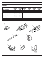
PRODUCT SPECIFICATIONS
MINIMUM HEARTH DIMENSIONS
MANUAL CONTROL
Model
A
VWF18
VWF24
VWF30
VWF36
B
C
MILLI-VOLT & HI/LO CONTROL
Model
A
B
C
VWF18
/ VWF24
/ VWF30
/ VWF36
/ Figure 1 - Minimum Hearth Dimensions
The manifold pressure for propane is 10" WC.
The manifold pressure for natural is 4"WC.
The minimum inlet gas supply pressure is 4" WC for natural and 10" WC for LP.
The maximum inlet gas supply pressure for this log set is 10" WC for natural and 13" WC for LP.
1RPLQDO5DWHV%78+U
9:)13
9:)1 9:)3 9:)1 9:)3 9:)1 9:)3 1RWH$FWXDOSHUIRUPDQFHÀDPHKHLJKW%78+UZLOOYDU\ZLWKVSHFL¿FLQVWDOODWLRQJDVSUHVVXUH
VKXWRIIYDOYHSRVLWLRQIXOO\RSHQYDOYHW\SHDQG¿UHER[GUDIWFRQGLWLRQV
27D8520
GETTING STARTED
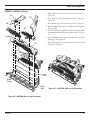
MAKE SURE YOU HAVE RECEIVED ALL PARTS:
Check your packing list to verify that all listed parts have been received. You should have the following:
BURNER - GRATE ASSEMBLY 18, 24, 30, 36"
• Burner and Grate Weldment Assembly
•
Lava Rocks (x2)
• Extenders with Knob (Manual Control Only)
• Glowing Embers (Rock Wool)
•
Damper Clamp
• Vermiculite
• Installation /Operating Instructions
•
3/8" Aluminum
• Control Cover
•
Shield Plate
tube with 3/8" 90° elbow, 1/2" to 3/8" WXEHÀWWLQJ
CAUTION
18", 24", 30" OR 36" CERAMIC FIBER OR REFRACTORY LOGS
• Individual Logs
• Installation Instructions
+DQGOHWKHJDVORJEXUQHUDVVHPEO\E\WKHJUDWHRQO\'RQRWSLFNWKHXQLWXSE\WKH
EXUQHU%XUQHUSDQLVDVHSDUDWHDVVHPEO\
*ORYHVDUHUHFRPPHQGHGZKHQKDQGOLQJFHUDPLF¿EHUORJVWRSUHYHQWVNLQLUULWDWLRQ
IURPORRVH¿EHUV/RJVDUHIUDJLOH²KDQGOHZLWKFDUH
Carefully inspect the contents for shipping damage. If any parts are missing or damaged, immediately inform the
dealer from whom you purchased the appliance. Do not attempt to install any part of the appliance unless you
have all parts in good condition.
ITEMS REQUIRED FOR INSTALLATION
Ensure that the following items are available before proceeding with installation:
• External regulator (for propane/L.P.G. only)
• Shutoff valve
• Piping which complies with local codes
• Pipe wrench
• Pipe sealant approved for use with propane/L.P.G. (Resistant to sulfur compounds)
'ULOOZLWKPDVRQU\ELWIRUPRXQWLQJWRWKHÁRRU
WARNING
MINIMUM OPENING AREA OF CHIMNEY DAMPER FOR VENTING
7KH¿UHSODFHDQGJDVORJVIXQFWLRQDVDV\VWHP,IWKH¿UHSODFHLVQRWGUDIWLQJSURSHUO\
DQGVSLOOLQJLQWRWKHURRPFKHFNZLWKDPDWFKRUDVPRNHVWLFNUHSRVLWLRQWKHGDPSHU
FODPSXQWLODSRVLWLYHGUDIWLVREWDLQHGE\RSHQLQJWKHGDPSHU,IQHJDWLYHSUHVVXUHLQ
KRPHSUHYHQWVKDYLQJDSRVLWLYHGUDIWFRQWDFW\RXUGHDOHUIRUDVVLVWDQFH
MINIMUM CHIMNEY HEIGHT AND FLUE OPENING
CHIMNEY HEIGHT
27D8520
FLUE OPENING
VTLQ
VTLQ
VTLQ
VTLQ
VTLQ
VTLQ
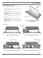
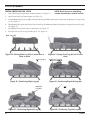
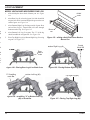
PLACEMENT IN A FIREPLACE WITH A RESTRICTIVE BARRIER
IMPORTANT INFORMATION FOR THE INSTALLATION OF THIS GAS LOG SET
7KHIROORZLQJDUHJXLGHOLQHVIRUSODFLQJD9:)ORJVHWLQDÀUHSODFHWKDWKDVDUHVWULFWLYHEDUULHUDORQJWKHERWWRPIURQW
RSHQLQJRIWKHÀUHSODFH6RPHH[DPSOHVRIEDUULHUVDUHJODVVVFUHHQGRRUIUDPHVDQGVXQNHQUHFHVVHGÀUHSODFHV
+HLJKWRI5HVWULFWLRQ;
0LQLPXP'HSWKRI)LUHSODFH)LUHER[
1RUHVWULFWLRQ
0DQXDO&RQWURO /0LOOL9ROWDQG+L/R&RQWURO
WR
*UHDWHUWKDQ/WR
*UHDWHUWKDQ
$1<%$55,(5*5($7(57+$17+5((,1&+(6
3/$&(',1)52172)7+(*$6/2*6(7,6127
5(&200(1'('%<7+(0$18)$&785(5
*ODVVGRRUIUDPHV
with adjustable
ORXYHUVVKRXOGKDYH
WKHORYHUV fully open
while the unit is in
RSHUDWLRQ
The log set should be
SODFHGDJDLQVWRUDVQHDU
DVSRVVLEOHWRWKHUHDUZDOO
RIWKH¿UHSODFH¿UHER[
+HLJKWRIUHVWULFWLYHEDUULHU ;
FDXVHGE\JODVVGRRUIUDPHV
UHFHVVHG¿UHSODFHVHWFIURP
WKHEDVHRUERWWRPVXUIDFHRIWKH
XQLW(Refer to Table).
'HSWKRI¿UHSODFH¿UHER[
(Refer toTable).
%DUULHUVVXFKDVWKHERWWRPRIDJODVVGRRUIUDPHSODFHGLQIURQWRIDJDVORJVHWFDQ
FKDQJHWKHDLUÀRZFKDUDFWHULVWLFVRIWKH¿UHSODFHZKLFKLQWXUQFDQFDXVHWKHXQLWWR
RYHUKHDWDQGPDOIXQFWLRQ$Q\GHYLDWLRQIURPWKHLQVWDOODWLRQJXLGHOLQHVRQWKLVVKHHW
will potentially void the warranty.
NOTE: Non combustible material such as
UHIUDFWRU\EULFNPD\EHXVHGWROLQHWKH
ÀRRURIWKH¿UHSODFHLQRUGHUWRUDLVHWKH
height of the gas log set in relation to a
UHVWULFWLYHEDUULHU
CAUTION
WARNING
Figure 2
,IWKH¿UHSODFHKDVDUHVWULFWLYHEDUULHU
and is equipped with a remote receiver,
LW PXVW EH SODFHG RXWVLGH RU WKH
FRPEXVWLRQFKDPEHU6HH³,QVWDOOLQJ
5HFHLYHU´RQSDJH
27D8520
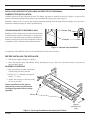
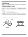
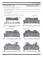
INSTALLATION
INSTALL AND OPERATE THE APPLIANCE AS DIRECTED IN THIS MANUAL.
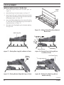
DAMPER STOP INSTALLATION
A damper stop must be provided with the unit. The damper stop must be installed as shown in (Figure 3) to prevent full
FORVXUHRIWKHÀUHSODFHGDPSHUEODGHDQGSURYLGHDPLQLPXPÁXHRSHQLQJSHUWDEOHRQSDJH
6KRXOG WKH FODPS QRW ÀW RU SURYLGH WKH UHTXLUHG SHUPDQHQW RSHQLQJ IURP WKH WDEOH KDYH WKH GDPSHU FXW WR SURYLGH D
minimum permanent opening or install a permanent stop.
FOR MASSACHUSETTS RESIDENTS ONLY
Damper Stop
Installation of this vented gas log set in the Commonwealth
of Massachusetts requires the damper be permanently
removed or welded in the fully open position. In addition, a
naturally vented gas log may not be installed in a bedroom
or bathroom in the Commonwealth of Masasachusetts.
Damper
Figure 3 - Damper Stop Installation
In compliance with ANSI Z21.60•CGA2.26 and National Fuel Gas Code, Section 6.
BEFORE INSTALLING THE APPLIANCE:
7XUQRIIJDVVXSSO\WRÀUHSODFHRUÀUHER[
&OHDQ WKH ÀUHSODFH ÁRRU DQG FKLPQH\ EHIRUH LQVWDOOLQJ WKH ORJ VHW 6HDO DQ\ DVK FOHDQRXW GRRUV WR SURWHFW WKH
unit from down drafts.
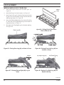
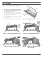
ASSEMBLY PROCEDURE
3ODFHJUDWHEXUQHUDVVHPEO\LQWRÀUHER[
with the front pan facing forward.
2. Drill two (2) 5/32" diameter holes approximately 1 1/2" deep.
$QFKRU WKH IURQW SDQ WR WKH ÁRRU XVLQJ
the screws provided.
Proper installation of the grate is
HVVHQWLDOWRSUHYHQWDQ\PRYHPHQW
of the gas logs and controls during
operation.
6FUHZV
,QMHFWRU
1DWXUDO*DV
RQO\
)LJXUH6HFXULQJ*UDWH%XUQHU$VVHPEO\LQWR)LUHER[
27D8520
7
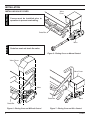
INSTALLATION
WARNING
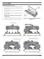
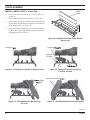
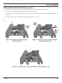
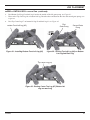
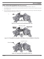
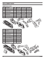
INSTALLING VALVE COVER
9DOYH
&RYHU
&RYHUV PXVW EH LQVWDOOHG SULRU WR
RSHUDWLRQWRSUHYHQWRYHUKHDWLQJ
*UDWH%DU
NOTICE
9DOYH
*UDWHEDUPXVWQRWWRXFKWKHYDOYH
)LJXUH3ODFLQJ&RYHURQ0DQXDO&RQWURO
9DOYH&RYHU
9DOYH&RYHU
9DOYH
*UDWH%DU
9DOYH
*UDWH%DU
)LJXUH3ODFLQJ&RYHURQ0LOOLYROW&RQWURO
8
)LJXUH3ODFLQJ&RYHURQ+L/R&RQWURO
27D8520
WARNING
WARNING
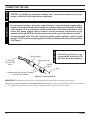
:,5,1*0,//,92/7
/DEHODOOZLUHVSULRUWRGLVFRQQHFWLRQ
ZKHQVHUYLFLQJFRQWUROV:LULQJHUURUV
FDQ FDXVH LPSURSHU DQG GDQJHURXV
operation. Verify proper operation after
VHUYLFLQJ
Do not connect to 110 volt supply.
THTP
0LOOLYROW
9DOYH
3LORW
TP
TH
6ZLWFK
WARNING
2SWLRQDO:DOO6ZLWFK
RU5HPRWH5HFLHYHU
Figure 8 - Wiring Diagram
The Milli-Volt (thermopile) is a self powered combination gas control
that does not require 110VAC to operate. Refer to Figure 8 and installation instructions provided with optional wall switch or remote control
.HHS ZLULQJ DZD\ IURP KHDW
for wiring instructions. A maximum length of 15 feet of 18awg two
source and hot surfaces.
conductor wire is to be used for wall switch. Note switches must be
suitable for millivolt operation. The optional wall switch and remote
UHFHLYHUPXVWEHPRXQWHGRXWVLGHWKHÀUHER[
CHECKING SYSTEM OPERATION
The milli-volt system and individual components may be
checked with a millivolt meter having a 0-1000MV range.
Conduct each check shown in chart below by connection
meter test leads to terminals as indicated.
CONNECT
METER
LEADS TO
TERMINALS
METER
READING
SHOULD BE
CHECK
TEST
TO
TEST
$
&203/(7(
6<67(0
7+7+73
&/26('
%
7+(5023,/(
287387
7+7+73
23(1
A. COMPLETE MILLI-VOLT SYSTEM CHECK
$5($',1*7+(50267$7&217$&76&/26('&21752/.12%210$,1%851(5
6+28/'%(&20(21
a. If the reading is more than 100 millivolts and the automatic valve still does not come on - replace the control.
b. If the closed circuit reading (“A” reading) is less than 100 millivolts, determine cause for low reading —
proceed as follows:
B. THERMOPILE OUTPUT READING CHECK
³%´5($',1*7+(50267$7&217$&7623(10$,1%851(52))
a. 325 millivolts minimum. If the minimum millivolt reading is not obtainable, readjust pilot for maximum millivolt
RXWSXW,IPLOOLYROWUHDGLQJLVVWLOOEHORZPLQLPXPVSHFLÀHGUHSODFHWKHUPRSLOH
27D8520
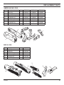
8VHQHZEODFNLURQSLSHVWHHOSLSHFRSSHUWXELQJRULQWHUQDOO\WLQQHGFRSSHUWXELQJ
&RSSHURULQWHUQDOO\WLQQHGFRSSHUWXELQJFDQRQO\DFFRUGLQJWRWKH1DWLRQDO)XHO*DV
&RGHVHFWLRQSURYLGLQJJDVPHHWVVXO¿GHOLPLWVDQGZKHUHSHUPLWWHGE\ORFDO
FRGHV *DV SLSLQJ V\VWHP PXVW EH VL]HG WR SURYLGH PLQLPXP LQOHW SUHVVXUH DW WKH
PD[LPXPÀRZUDWH%78+U8QGXHSUHVVXUHORVVZLOORFFXULIWKHSLSHLVWRRVPDOO
$ PDQXDO VKXWRII YDOYH PXVW EH LQVWDOOHG XSVWUHDP RI WKH DSSOLDQFH 8QLRQ WHH DQG
SOXJJHG137SUHVVXUHWDSSLQJSRLQWVKRXOGEHLQVWDOOHGXSVWUHDPRIWKHDSSOLDQFH
See Figure 9.
3LSH&RXSOLQJ
7R*DV/RJ
6HWRUWR*DV
9DOYH
*DV6XSSO\,QOHW
WARNING
NOTICE
127,&( $ TXDOL¿HG JDV DSSOLDQFH LQVWDOOHU PXVW FRQQHFW WKH DSSOLDQFH WR WKH JDV
VXSSO\&RQVXOWDOOORFDOFRGHVEHIRUHLQVWDOODWLRQ
CAUTION
CONNECTING THE GAS
&RQQHFWLQJ GLUHFWO\ WR DQ
XQUHJXODWHG SURSDQH/3*
tank can cause an explosion.
6KXWRII
9DOYH
3LSH
/RFDWLRQVWKDWWKH3UHVVXUH7DSSLQJ
3RLQW0D\EH,QVWDOOHG
Figure 9 - Gas Connection
IMPORTANT: +ROGDSSOLDQFHÀUPO\ZLWKDZUHQFKWRSUHYHQWPRYHPHQWZKHQFRQQHFWLQJWRLQOHWSLSLQJ
Always use an external regulator for all propane/LPG gas logs only, to reduce the supply tank pressure to a maximum of
13" w.c. High pressure natural gas systems require a regulator to reduce supply pressure to 10" W.C.
27D8520
CONNECTING THE GAS
The gas log set gas inlet connection is 3/8" NPT at the regulator, inlet on the right side facing the gas log. If a left
side connection is required, the connecting pipe may be led under the rear of the gas logs or behind the grate for
connection to the inlet.
Test all gas joints from the gas meter to the appliance regulator for leaks using a gas analyzer or soap and water solution after
completing connection. DO NOT USE AN OPEN FLAME.
Check the gas pressure with the appliance burning.
MANUAL AND HI/LO CONTROL (Figure 10)
The pressure regulator is preset and locked to discourage
WDPSHULQJ,IWKHSUHVVXUHLVQRWDVVSHFLÀHGUHSODFHZLWK
the correct part from the parts list in this manual.
Remove 1/8" NPT plug, located on side of regulator body.
,QVWDOO ÀWWLQJ DQG WXELQJ WR SUHVVXUH JDXJH $IWHU WDNLQJ
pressure reading, re-install test plug. which should be
checked at the pressure test point. Check for gas leaks.
7HVW3OXJ
Figure 10 - Pressure Test Point Location
MILLI-VOLT CONTROL (Figure 11)
The valve regulator controls the burner pressure which should
be checked at the pressure test point. Turn captured screw
counter clockwise 2 or 3 turns and then place tubing to pressure gauge over test point (Use test port labeled “OUT”).
After taking pressure reading, be sure and turn captured
VFUHZFORFNZLVHÀUPO\WRUHVHDO'RQRWRYHUWRUTXH&KHFN
for gas leaks.
7HVW3RUW
³2XW´
Figure 11 - Pressure Test Point Location
27D8520
LOG PLACEMENT
FILLING THE BURNER PAN
Fill the burner pan with vermiculite to the bottom of the rear log and sloped to the front edge of the burner pan. Excess verPLFXOLWHFDQVSLOOIRUZDUGRUWRWKHVLGHRIWKHEXUQHUSDQ'RQRWRYHUÀOOWKHSURSDQHPRGHO'RQRWFRYHUWKHSLORWLI63.
or MVVK is installed) with vermiculite or rock wool (embers).
3/$&(0(17 2) */2:,1* (0%(56 52&. :22/
7KH:LOGÀUHÁDPHDSSHDUDQFHFDQYDU\GXHWRGLIIHUHQFHVLQGUDIWDQGÀUHSODFHFRQÀJXUDWLRQVDQGHPEHUSODFHPHQW$IWHU
installing rear (#1) and front logs (#2 and #3), cover the entire top surface of the vermiculite in the burner pan with the rock
wool supplied with unit. Tear the rock wool into pieces approximately 1/2" in size (roughly the size of a nickel) and cover
the burner evenly. Do no use more rock wool than the amount supplied with the unit. To enhance the appearance of the
:LOGÀUHÁDPHLWLVUHFRPPHQGHGWRIRUPDPRXQGRIURFNZRROLQWKHFHQWHURIWKHEXUQHUWRKLJKYLVLEOHWKURXJK
the two front logs.
PLACEMENT OF DECORATIVE VOLCANIC ROCK
Sprinkle volcanic rock in front of front glowing embers and to both sides.
DO NOT SPRINKLE ON BURNERS, EMBER BED, PILOT OR LOGS.
,03257$17'RQRWKDQGOHORJVZLWK\RXUEDUHKDQGV$OZD\VZHDUJORYHVWRSUHYHQWVNLQLUULWDWLRQ
IURPFHUDPLF¿EHUV$IWHUKDQGOLQJORJVZDVK\RXUKDQGVJHQWO\ZLWKVRDSDQGZDWHUWRUHPRYHDQ\
WUDFHVRI¿EHUV
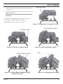
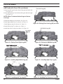
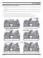
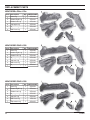
VWF18 MASSIVE OAK LOGS
1.Slide shield plate down back of burner pan. See Figure 12.
&HQWHUUHDUORJRQJUDWHEDUVDQGÁXVKZLWKUHDURIWKHJUDWHSee Figure 13.
5HDU/RJ
6KLHOG
3ODWH
Burner
3DQ
)LJXUH6OLGLQJ6KLHOG3ODWH'RZQ%DFNRI
%XUQHU3DQ
)LJXUH&HQWHULQJ5HDU/RJRQ*UDWH%DUV
Continued
27D8520
LOG PLACEMENT
3.
Place front left log #2 on the front of the grate and to the left.
See Figure 14.
4.
Place front right log #3 on the front of the grate and to the
right. See Figure 15.
)URQW/HIW/RJ
127($OORZEHWZHHQWKHEDFNORJDQGWKHWZR
front logs.
5.
Install left side middle log #4 as shown. See Figure 16.
6.Install right side middle log (#5). See Figure 17.
7.Install right top log #5 as shown. See Figure 18.
)LJXUH3ODFLQJ)URQW/HIW/RJRQ*UDWH
/HIW6LGH0LGGOH/RJ
)URQW5LJKW/RJ
)LJXUH3ODFLQJ)URQW5LJKW/RJ
5LJKW6LGH0LGGOH/RJ
)LJXUH,QVWDOOLQJ5LJKW6LGH0LGGOH/RJ
DQG/HIW7RS/RJ
27D8520
)LJXUH3ODFLQJ/HIW0LGGOH/RJ
5LJKW 7RS/RJ
7
)LJXUH,QVWDOOLQJ5LJKW7RS/RJ
LOG PLACEMENT
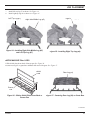
VWF24 MASSIVE OAK LOGS
1.
Slide shield plate down back of burner pan. See Figure 19.
&HQWHUUHDUORJRQJUDWHEDUVDQGÁXVKZLWKUHDURIWKH
grate. See Figure 20.
3.
Place front left log #2 on the front of the grate and to the left.
See Figure 21.
4.
Place front right log #3 on the front of the grate and to the
right. See Figure 4.
127($OORZEHWZHHQWKHEDFNORJDQGWKH
two front logs.
5.
Install left side middle log #4 as shown. See Figure 22.
6.
Install right side middle log #5 as shown. See Figure 23.
6KLHOG
3ODWH
Burner
3DQ
)LJXUH6OLGLQJ6KLHOG3ODWH'RZQ%DFNRI
%XUQHU3DQ
5HDU/RJ
)URQW /HIW /RJ )LJXUH&HQWHULQJ5HDU/RJRQ*UDWH%DUV
)URQW5LJKW/RJ
)LJXUH3ODFLQJ)URQW5LJKW/RJ
)LJXUH3ODFLQJ)URQW/HIW/RJRQ*UDWH
/HIW6LGH0LGGOH/RJ
)LJXUH3ODFLQJ/HIW0LGGOH/RJ
Continued
27D8520
LOG PLACEMENT
7.
Install left top log #7 as shown. See Figure 24.
8.
Install right top log #6 as shown. See Figure 25.
/HIW 7RS/RJ
7
5LJKW 7RS/RJ
7
5LJKW6LGH0LGGOH/RJ
)LJXUH,QVWDOOLQJ5LJKW6LGH0LGGOH/RJ
DQG/HIW7RS/RJ
)LJXUH,QVWDOOLQJ5LJKW7RS/RJ
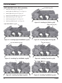
VWF30 MASSIVE OAK LOGS
1.Slide shield plate down back of burner pan. See Figure 26.
&HQWHUUHDUORJRQJUDWHEDUVDQGÁXVKZLWKUHDURIWKHJUDWHSee Figure 27.
6KLHOG
3ODWH
5HDU/RJ
Burner
3DQ
)LJXUH6OLGLQJ6KLHOG3ODWH'RZQ%DFNRI
%XUQHU3DQ
)LJXUH&HQWHULQJ5HDU/RJRQ*UDWH%DUV
Continued
27D8520
LOG PLACEMENT
VWF30 MASSIVE OAK LOGS FRQWLQHXG
3.Place front left log #2 on the front of the grate and to the left.
See Figure 28.
)URQW/HIW/RJ
4.Place front right log #3 on the front of the grate and to the right.
See Figure 29.
127($OORZEHWZHHQWKHEDFNORJDQGWKHWZR
front logs.
5.Install left middle log #4 as shown. See Figure 30.
6.Install right middle log #5 as shown. See Figure 31.
7.Install right top log #6 as shown. See Figure 32.
)LJXUH3ODFLQJ)URQW/HIW/RJRQ*UDWH
8.Install left top log #7 as shown. See Figure 33.
9.Install top crossover log #8 as shown. See Figure 34.
/HIW0LGGOH/RJ
)URQW5LJKW
J
)LJXUH3ODFLQJ)URQW5LJKW/RJ
5LJKW 0LGGOH /RJ )LJXUH,QVWDOOLQJ5LJKW0LGGOH/RJ
/HIW 7RS/RJ
7
)LJXUH,QVWDOOLQJ/HIW7RS/RJ
)LJXUH3ODFLQJ/HIW0LGGOH/RJ
5L KW 7
/
)LJXUH,QVWDOOLQJ5LJKW7RS/RJ
7
7RS&URVVRYHU/RJ
)LJXUH,QVWDOOLQJ7RS&URVVRYHU/RJ
27D8520
LOG PLACEMENT
VWF36 MASSIVE OAK LOGS
1.
Slide shield plate down back of burner pan. See Figure
35.
&HQWHUUHDUORJRQJUDWHEDUVDQGÁXVKZLWKUHDURI
the grate. See Figure 36.
3.
Place front left log #2 in front of the plate and to the
left. See Figure 37.
127($OORZEHWZHHQWKHEDFNORJDQGWKH
front left log.
4.
Place center front log #3 on middle grate prong. See
Figure 38.
5.
Place front right log #4 in front of the plate and to the
right. See Figure 39.
127($OORZEHWZHHQWKHEDFNORJDQGWKH
right front log.
5HDU/RJ
6KLHOG
3ODWH
%XUQHU3DQ
Figure 35 - Sliding Shield Plate Down
%DFNRI%XUQHU3DQ
)URQW/HIW/RJ
)LJXUH&HQWHULQJ5HDU/RJ
&HQWHU)URQW/RJ
)LJXUH3ODFLQJ&HQWHU)URQW/RJ
)LJXUH3ODFLQJ)URQW/HIW/RJ
)URQW5LJKW/RJ
)LJXUH3ODFLQJ5LJKW)URQW/RJ
Continued
27D8520
LOG PLACEMENT
VWF36 MASSIVE OAK LOGS FRQWLQXHG
6.
Install left side log #5. See Figure 40.
7.
Install right side middle log #7. See Figure 41.
8.
Install right side log #6. See Figure 42.
9.
Install top left middle log #8. See Figure 43.
/HIW6LGH/RJ
10. Install top left log #9. See Figure 44.
11. Install top right log #10. See Figure 45.
12. Install top middle log #l1. See Figure 46.
)LJXUH,QVWDOOLQJ/HIW6LGH/RJ
5LJKW6LGH0LGGOH/RJ
)LJXUH,QVWDOOLQJ5LJKW6LGH0LGGOH/RJ
7
7RS/HIW0LGGOH/RJ
)LJXUH,QVWDOOLQJ7RS/HIW0LGGOH/RJ
7
7RS5LJKW/RJ
)LJXUH,QVWDOOLQJ7RS5LJKW/RJ
5LJKW6LGH/RJ
)LJXUH,QVWDOOLQJ5LJKW6LGH/RJ
7
7RS/HIW/RJ
)LJXUH,QVWDOOLQJ7RS/HIW/RJ
7RS 0LGGOH /RJ 7
)LJXUH,QVWDOOLQJ7RS0LGGOH/RJ
27D8520
LOG PLACEMENT
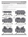
VWF18 AMERICAN OAK LOGS
127((DFKORJKDVDQLGHQWLI\LQJ
number emobssed on bottom surface.
1.
Place Back Log #2 on grate bars on back of grate. See Figure 47.
2.
Place Front Log #1 on front of grate. See Figure 48.
3RVLWLRQ5LJKW/HIW0LGGOH/RJRQWRSULJKWRI/RJDQG/RJ0DNHVXUHEDFNRI/RJÀWVLQULJKWJURYHLQ
top of Log #2. See Figure 49.
3ODFH5LJKW/HIW0LGGOH/RJRQWRSOHIWRI/RJDQG/RJ0DNHVXUHEDFNRI/RJÀWVLQOHIWJURYHLQWRSRI
Log #2. See Figure 50.
5.
Rest Top Right/Left Log #4 on Log # 3 and Log #1. See Figure 51.
6.
Rest Top Right/Left Log #4 on Log #3 and Log #1. See Figure 52.
%DFN
Lo
)URQW/RJ
)LJXUH3ODFLQJ%DFN/RJRQ*UDWH
%DUVLQ%DFNRI*UDWH
5
)LJXUH3RVLWLRQLQJ5LJKW/HIW0LGGOH/RJ
)LJXUH3ODFLQJ)URQW/RJRQ)URQWRI*UDWH
Right/Left
Middle
/RJ
)LJXUH3RVLWLRQLQJ5LJKW/HIW0LGOH/RJ
7
7RS5LJKW/HIW/RJ
7RS 5LJKW/HIW /RJ 7
)LJXUH3RVLWLRQLQJ7RS5LJKW/HIW/RJ
27D8520
)LJXUH3RVLWLRQLQJ7RS5LJKW/HIW/RJ
LOG PLACEMENT
VWF24 AMERICAN OAK LOGS
127((DFKORJKDVDQLGHQWLI\LQJ
number emobssed on bottom surface.
1.
Place Back Log #2 on grate bars on back of grate. See Figure 53.
2.
Place Front Log #1 on front of grate. See Figure 54.
3RVLWLRQ5LJKW/RJRQWRSULJKWRI/RJDQG/RJ0DNHVXUHEDFNRI/RJÀWVLQULJKWJURYHLQWRSRI/RJ
#2. See Figure 55.
3ODFH5LJKW/HIW/RJRQWRSOHIWRI/RJDQG/RJ0DNHVXUHEDFNRI/RJÀWVLQOHIWJURYHLQWRSRI/RJ
See Figure 56.
5.
Rest Right/Left Log #4 on Log # 3 and Log #1. See Figure 57.
6.
Rest Top Left Log #5 on Log #4 and Log #1. See Figure 58.
%DFN/RJ
)URQW/RJ
)LJXUH3ODFLQJ%DFN/RJRQ*UDWH%DUVLQ
%DFNRI*UDWH
5LJKW/RJ
)LJXUH3RVLWLRQLQJ5LJKW/RJ
Right/Left
/RJ
)LJXUH3RVLWLRQLQJ5LJKW/HIW/RJ
)LJXUH3ODFLQJ)URQW/RJRQ)URQWRI
Grate
5LJKW/HIW/RJ
)LJXUH3RVLWLRQLQJ5LJKW/HIW/RJ
7RS/HIW/RJ
7
)LJXUH3RVLWLRQLQJ7RS/HIW/RJ
27D8520
LOG PLACEMENT
VWF30 AMERICAN OAK LOGS
127((DFKORJKDVDQLGHQWLI\LQJ
number emobssed on bottom surface.
1.
Place Back Log #2 on grate bars on back of grate. See Figure 59.
2.
Place Front Log #1 on front of grate. See Figure 60.
3RVLWLRQ5LJKW/HIW0LGGOH/RJRQWRSULJKWRI/RJDQG/RJ0DNHVXUHEDFNRI/RJÀWVLQULJKWJURYHLQ
top of Log #2. See Figure 61.
3ODFH5LJKW/HIW0LGGOH/RJRQWRSOHIWRI/RJDQG/RJ0DNHVXUHEDFNRI/RJÀWVLQOHIWJURYHLQWRSRI
Log #2. See Figure 62.
5.
Rest Top Right/Left Log #4 on Log # 3 and Log #1. See Figure 5.
6.
Rest Top Right/Left Log #4 on Log #3 and Log #1. See Figure 6.
)URQW/RJ
%DFN/RJ
)LJXUH3ODFLQJ%DFN/RJRQ*UDWH%DUV
RQ%DFNRI*UDWH
Right/Left Middle /RJ
)LJXUH3RVLWLRQLQJ5LJKW/HIW0LGGOH/RJ
7
7RS5LJKW/RJ
)LJXUH3RVLWLRQLQJ7RS5LJKW/HIW/RJ
)LJXUH3ODFLQJ)URQW/RJRQ)URQW*UDWH
/HIW0LGGOH/RJ
)LJXUH3RVLWLRQLQJ/HIW0LGGOH/RJ
7
7RS/HIW/RJ
)LJXUH3RVLWLRQLQJ7RS5LJKW/HIW/RJ
Continued
27D8520
LOG PLACEMENT
VWF30 AMERICAN OAK LOGS FRQWLQXHG
7.
Place Left Crossover Log #5 on Log #2 and Log #5. See Figure 64.
8.
Place Right Crossover Log #5 on Log #3 and Log #5. See Figure 64 .
/HIW&URVVRYHU
/RJ
)LJXUH3ODFLQJ/HIW&URVVRYHU/RJ
5LJKW&URVVRYHU/RJ
)LJXUH3ODFLQJ5LJKW&URVVRYHU/RJ
27D8520
LOG PLACEMENT
MODELS VWF24 B /RJV
1. Slide shield plate down back of burner pan. See
Figure 66.
2. Place Back Log #1 on grate bars on back of grate. See
Figure 66.
3. Place Middle Log #2 in front of Log #1. See Figure 20.
4. Position Right Front Log #3 on right front side of grate.
See Figure 66.
5. Position Left Front Log #4 on left front side of grate. Make
sure notch in bottom of log sits on grate prong. See Figure
66.
1RWFK
6. Rest Top Right Log #5 across top right sides of Log #1
and Log #2. See Figure 66.
7. Rest Top Left Log #6 across top left side of Log #1 and
Log #2. See Figure 66.
6KLHOG
3ODWH
*UDWH
3URQJ
*UDWH
Bar
)LJXUH9:)%%LUFK/RJ3ODFHPHQW
)LJXUH9:)%%LUFK/RJ3ODFHPHQW
27D8520
LOG PLACEMENT
MODELS VWF24/18 SPLIT RIVER OAK
1.
Slide shield plate down back of burner pan. See
Figure 68.
2.
Place Back Log #1 on back of grate. See Figure 69.
3.
Place Front Left Log #2 in front of back log on left arm
of grate. Rest end of bottom left log between second and
third prong of grate. See Figure 70.
4.
Place end of Bottom Right Log #3 on cutout of back log
#1. Rest other end of right bottom log to the outside of
right grate prong. See Figure 71.
6KLHOG
3ODWH
)LJXUH6OLGLQJ6KLHOG3ODWH'RZQ%DFNRI
%XUQHU3DQ
)URQW/H
5HDU/RJ
/HIW$UP
RI*UDWH
6HFRQG3URQJ
)LJXUH3ODFLQJ5HDU/RJRQ%DFNRI*UDWH
7KLUG3URQJ
)LJXUH3ODFLQJ)URQW/HIW/RJRQ
Left Arm of Grate
%RWWRP)URQW/HIW/RJ
5LJKW
)LJXUH3ODFLQJ%RWWRP5LJKW/RJ
on Grate
)LJXUH,QVWDOOLQJ%RWWRP)URQW/HIW/RJ
Continued
27D8520
LOG PLACEMENT
MODELS VWF24/18 SPLIT RIVER OAK FRQWLQXHG
6.
Rest Bottom Left Log #5 on back log #1 and to the outside of the left grate prong. See Figure 72.
5.
Rest right end of Top Right Log #4 on bottom right log. See Figure 73.
3ODFHHQGRI7RS/HIW/RJRQERWWRPOHIWORJ5HVWWKHRWKHUHQGEHWZHHQWKHÀUVWDQGVHFRQGJUDWHSURQJV See
Figure 74.
8.
Rest Top Center Log #7 on bottom left log #2 and back log #1. See Figure 75.
7
7RS5LJKW/RJ
7RS/HIW
7
/RJ
W
URQJ
*UDWH
QJ
FRQG
RQJ
UDWH
)LJXUH5HVWLQJ7RS5LJKW/RJRQ
%RWWRP/HIW/RJ
)LJXUH5HVWLQJ7RS/HIW/RJRQ%RWWRP
/HIW/RJDQG%DFN/RJ
7
7RS&HQWHU/RJ
)LJXUH5HVWLQJ&HQWHU7RS/RJ%RWWRPOHIW/RJDQG%DFN/RJ
27D8520
LOG PLACEMENT
MODELS VWF30/24 SPLIT RIVER OAK
1.
Slide shield plate down back of burner pan. See
Figure 76.
2.
Place Back Log #1 on back of grate. See Figure 77.
3.
Place Front Left Log #2 in front of back log on left arm
of grate. Rest end of bottom left log between second and
third prong of grate. See Figure 78.
4.
Place end of Bottom Right Log #3 on cutout of back log
#1. Rest other end of right bottom log to the outside of
right grate prong. See Figure 79.
5.
Rest right end of Top Right Log #4 on bottom right log.
See Figure 80.
6KLHOG
3ODWH
)LJXUH6OLGLQJ6KLHOG3ODWH'RZQ%DFNRI
%XUQHU3DQ
%DFN/RJ
)UR
Lef
$UP
*UD
6HFRQG3URQJ
)LJXUH3ODFLQJ5HDU/RJRQ%DFNRI*UDWH
%RWWRP
Right Log
)LJXUH3ODFLQJ%RWWRP5LJKW/RJRQ*UDWH
7KLUG3URQJ
)LJXUH3ODFLQJ)URQW/HIW/RJRQ
Left Arm of Grate
/HIW*UDWH3URQJ
7RS 5LJKW /RJ 7
)LJXUH5HVWLQJ7RS5LJKW/RJRQ
%RWWRP/HIW/RJ
Continued
27D8520
LOG PLACEMENT
MODELS VWF30/24 SPLIT RIVER OAK FRQWLQXHG
6.
Rest Bottom Left Log #5 on back log #1 and to the outside of the left grate prong. See Figure 81.
3ODFHHQGRI7RS/HIW/RJRQERWWRPOHIWORJ5HVWWKHRWKHUHQGEHWZHHQWKHÀUVWDQGVHFRQGJUDWHSURQJV See
Figure 82.
8.
Rest Top Center Log #7 on bottom left log #2 and back log #1. See Figure 83.
)LUVW
*UDWH3URQJ
%RWWRP)URQW/HIW/RJ
)LJXUH,QVWDOOLQJ%RWWRP)URQW/HIW/RJ
6HFRQG*UDWH
3URQJ
)LJXUH5HVWLQJ7RS/HIW/RJRQ%RWWRP
/HIW/RJDQG%DFN/RJ
7
7RS&HQWHU/RJ
)LJXUH5HVWLQJ&HQWHU7RS/RJ%RWWRPOHIW
/RJDQG%DFN/RJ
27D8520
LOG PLACEMENT
MODELS VWF36/30 SPLIT RIVER OAK
1.
Slide shield plate down back of burner pan. See
Figure 84.
2.
Place Back Log #1 on back of grate. See Figure 85.
3.
Place Front Left Log #2 in front of back log on left arm
of grate. Rest end of bottom left log between third and
fourth prong of grate. See Figure 86.
4.
Place end of Bottom Right Log #3 on cutout of back log
#1. Rest other end of right bottom log to the outside of
right grate prong. See Figure 87.
5.
Rest right end of Top Right Log #4 on bottom right log.
See Figure 88.
6KLHOG
3ODWH
Figure 84 - Sliding Shield Plate Down
%DFNRI%XUQHU3DQ
5HDU/RJ
)URQW/HIW/RJ
Lef
$UP
*UD
J
)LJXUH3ODFLQJ5HDU/RJRQ%DFNRI*UDWH
%RWWRP
)LJXUH3ODFLQJ%RWWRP5LJKW/RJRQ
Grate
)RXUWK3URQJ
)LJXUH3ODFLQJ)URQW/HIW/RJRQ
Left Arm of Grate
7
7RS5LJKW/RJ
/HIW*UDWH3URQJ
)LJXUH5HVWLQJ7RS5LJKW/RJRQ
%RWWRP/HIW/RJ
Continued
27D8520
LOG PLACEMENT
MODELS VWF36/30 SPLIT RIVER OAK FRQWLQXHG
6.
Rest Bottom Left Log #5 on back log #1 and to the outside of the left grate prong. See Figure 89.
3ODFHHQGRI7RS/HIW/RJRQERWWRPOHIWORJ5HVWWKHRWKHUHQGEHWZHHQWKHÀUVWDQGVHFRQGJUDWHSURQJV See
Figure 90.
8.
Rest Top Center Log #7 on bottom left log #2 and back log #1. See Figure 91.
9.
Rest Right Front Log #8 on top right log #4 and front of burner pan. See Figure 92
%RWWRP)URQW/HIW/RJ
)LUVW*UDWH3URQ
7RS /HIW
7
G*UDWH
RQJ
)LJXUH,QVWDOOLQJ%RWWRP)URQW/HIW/RJ
)LJXUH5HVWLQJ7RS/HIW/RJRQ%RWWRP
/HIW/RJDQG%DFN/RJ
5LJKW)URQW/RJ
7
7RS&HQWHU
)LJXUH5HVWLQJ&HQWHU7RS/RJ%RWWRP
OHIW/RJDQG%DFN/RJ
27D8520
)LJXUH5HVWLQJ)URQW5LJKW/RJRQ7RS
5LJKW/RJDQG)URQWRI%XUQHU3DQ
LOG PLACEMENT
MODELS VWF18 SPLIT PINE
1.
Slide shield plate down back of burner pan. See Figure
93.
2.
Place Left Front Log #1A on front left of grate. See
Figure 94.
3.
Place Right Front Log #1B on front right of the grate.
See Figure 95.
4.
Place front end of Side Support Log #2 on top left of
Log #1A. Rest other end of Log #2 on rear grate bar.
See Figure 96.
5.
Fit cutout in the bottom left of Rear Log #3 over the
back end of log #1A. Rest right end of Log #3 on rear
grate bar. See Figure 97.
6KLHOG
3ODWH
Burner
3DQ
)LJXUH6OLGLQJ6KLHOG3ODWH'RZQ%DFNRI
%XUQHU3DQ
/HIW)URQW/RJ$
)LJXUH3ODFLQJ/HIW)URQW/RJ$RQ*UDWH
)LJXUH3ODFLQJ5LJKW)URQW/RJ%RQ*UDWH
5HDU/RJ
6LGH6XSSRUW/RJ
)LJXUH3ODFLQJ6LGH6XSSRUW/RJRQ7RS
/HIWRI/RJ$
)LJXUH,QVWDOOLQJ5HDU/RJ
Continued
27D8520
LOG PLACEMENT
MODELS VWF18 SPLIT PINE FRQWLQXHG
6.
Rest front end of Right Log #4 on right top of Log #1B. The back end of Log #4 rests to right hump on Log #3. See
Figure 98.
7.
Place front of Right Middle Log #5 on top right of Log #4. Rest back end of Log #5 on top right of Log #3. See Figure
99.
8.
Lay Top Center Log #7 across log #5 with front end resting on Log #1. See Figure 100.
9.
Place front end of Top Left Log #8 on Log #7. Let back end of Log #8 rest on Log #6. See Figure 101.
)LJXUH,QVWDOOLQJ5LJKW/RJ
)LJXUH,QVWDOOLQJ5LJKW0,GGOH/RJ
7RS /HIW /RJ 7
7
7RS&HQWHU/RJ
)LJXUH,QVWDOOLQJ7RS&HQWHU/RJ
27D8520
)LJXUH,QVWDOOLQJ7RS/HIW/RJ
LOG PLACEMENT
MODELS VWF24 SPLIT PINE
1.
Slide shield plate down back of burner pan. See Figure
102.
2.
Place Left Front Log #1A on front left of grate. See
Figure 103.
3.
Place Right Front Log #1B on front right of the grate.
See Figure 104.
4.
Place front end of Side Support Log #2 on top left of
Log #1A. Rest other end of Log #2 on rear grate bar.
See Figure 105.
5.
Fit cutout in the bottom left of Rear Log #3 over the
back end of Log #2. Rest right end of Log #3 on rear
grate bar. See Figure 106.
/HIW)URQW/RJ$
)LJXUH3ODFLQJ/HIW)URQW/RJ$RQJUDWH
6KLHOG
3ODWH
Burner
3DQ
)LJXUH6OLGLQJ6KLHOG3ODWH'RZQ%DFNRI
%XUQHU3DQ
5LJKW)URQW/RJ%
)LJXUH3ODFLQJ5LJKW)URQW/RJ%RQ
grate
5HDU/RJ
6LGH 6XSSRUW /RJ )LJXUH3ODFLQJ6LGH6XSSRUW/RJRQ
7RS/HIWRI/RJ$
)LJXUH,QVWDOOLQJ5HDU/RJ
Continued
27D8520
LOG PLACEMENT
MODELS VWF24 SPLIT PINE FRQWLQXHG
6.
Rest front end of Right Log #4 on right top of Log #1B.
The back end of Log #4 rests to right hump on Log #3.
See Figure 107.
7.
Place front of Right Middle Log #5 on top right of Log
#1B. Rest back end of Log #5 on top right of Log #4.
See Figure 108.
8.
Rest front of Left Log #6 just left of the middle of Log
#1A and back end of Log #6 just left of middle of Log
#3. See Figure 109.
9.
Lay Top Center Log #7 across log #3 with front end
resting on Log #5. See Figure 110.
5LJKW/RJ
)LJXUH,QVWDOOLQJ5LJKW/RJ
10. Place front end of Top Left Log #8 on Log #7. Let back
end of Log #8 rest on Log #6. See Figure 111.
)LJXUH,QVWDOOLQJ5LJKW0,GGOH/RJ
7
7RS&HQWHU/RJ
)LJXUH,QVWDOOLQJ7RS&HQWHU/RJ
27D8520
)LJXUH,QVWDOOLQJ/HIW/RJ
7
7RS/HIW/RJ
)LJXUH,QVWDOOLQJ7RS/HIW/RJ
LOG PLACEMENT
MODELS VWF30 SPLIT PINE
1.
Slide shield plate down back of burner pan. See Figure
112.
2.
Place Left Front Log #1A on front left of grate. See
Figure 113.
3.
Place Right Front Log #1B on front right of the grate.
See Figure 114.
4.
Place front end of Side Support Log #2 on top left of
Log #1A. Rest other end of Log #2 on rear grate bar.
See Figure 115.
5.
Fit cutout in the bottom left of Rear Log #3 over the back
end of log #2. Rest right end of Log #3 on rear grate bar.
See Figure 116.
/HIW)URQW/RJ$
)LJXUH3ODFLQJ/HIW)URQW/RJ$RQ*UDWH
6KLHOG
3ODWH
Burner
3DQ
)LJXUH6OLGLQJ6KLHOG3ODWH'RZQ%DFNRI
%XUQHU3DQ
5LJKW)URQW/RJ%
)LJXUH3ODFLQJ5LJKW)URQW/RJ%RQ
Grate
5HDU/RJ
6LG 6
W/
)LJXUH3ODFLQJ6LGH6XSSRUW/RJRQ7RS
/HIWRI/RJ$
)LJXUH,QVWDOOLQJ5HDU/RJ
Continued
27D8520
LOG PLACEMENT
MODELS VWF30 SPLIT PINE FRQWLQXHG
6.
Rest front end of Right Log #4 on right top of Log #1B. The back end of Log #4 rests to right hump on Log #3. See
Figure 117.
7.
Rest front of Left Log #6 just left of the middle of Log #1A and back end of Log #6 just left of middle of Log #3. See
Figure 118.
8.
Place front of Right Middle Log #5 on top right of Log #1B. Rest back end of Log #5 on top right of Log #4. See Figure
119.
9.
Lay Top Center Log #7 across log #5 with front end resting on Log #1. See Figure 120.
10. Place front end of Top Left Log #8 on Log #6. Let back end of Log #8 rest on Log #3. See Figure 121.
11. Rest front of Top Top Log #9 on Log #8 and back of Log #9 on left end of Log #3. See Figure 122.
)LJXUH,QVWDOOLQJ5LJKW/RJ
)LJXUH,QVWDOOLQJ/HIW/RJ
5LJKW 0LGGOH /RJ 7
7R
)LJXUH,QVWDOOLQJ5LJKW0LGGOH/RJ
7RS /HIW /RJ 7
)LJXUH,QVWDOOLQJ7RS/HIW/RJ
27D8520
)LJXUH,QVWDOOLQJ7RS&HQWHU/RJ
7RS 7RS/HIW
7
7
/RJ
)LJXUH,QVWDOOLQJ7RS7RS/HIW/RJ
est
gh
og
LOG PLACEMENT
MODEL VWF24/18WP WEATHERED PINE LOG
1.
Slide shield plate down back of burner pan. See Figure
123.
3ODFH5HDU/RJRQEDFNRIJUDWH/HIWVLGHVKRXOGÀW
on grate in front of rear stand. Right side goes on the rear
stand of grate. See Figure 124.
3.
Place Bottom Right Log #2 along outside of grate. Rest
end on Rear Log #1. Control knob will stick through
bottom notch of log. See Figure 125.
4.
Place Bottom Left Log #3 on grate. The “V” of the log
should straddle the end grate bar. See Figure 126.
5.
Place Top Right Log #4 on Bottom Right Log #2 resting
on grate. See Figure 127.
6KLHOG
3ODWH
Burner
3DQ
)LJXUH6OLGLQJ6KLHOG3ODWH'RZQ%DFNRI
%XUQHU3DQ
st%RWWRP5LJKW/RJ
ch
Rear Log
&RQWURO
.QRE:LOO
*R+HUH
Rear
6WDQGRI
*UDWH
nd
he
1.
of
ee
)LJXUH3ODFLQJ5HDU/RJRQ%DFN*UDWH
³9´6WUDGGOLQJ
*UDWH%DU
%RWWRP/HIW/RJ
)LJXUH6WUDGGOLQJ³9´RI%RWWRP/HIW/RJ
RQ*UDWH%DU
)LJXUH3ODFLQJ%RWWRP5LJKW/RJ
7
7RS5LJKW/RJ
)LJXUH3ODFLQJ7RS5LJKW/RJ
27D8520
LOG PLACEMENT
MODEL VWF24/18WP WEATHERED PINE LOG FRQWLQXHG
6.
Place Top Left Log #5 behind Rear Log #1 on the notch on rear left of grate stand. See Figure 128.
7.
Place Mid Front Log #6 on grate between center and middle left grate bars. Fit notch on back of log on the cross grate
bar. See Figure 129.
7RS /HIW /RJ 7
)LJXUH3ODFLQJ7RS/HIW/RJEHKLQG5HDU/RJ
0LG)URQW/RJ
&HQWHU*UDWH%DU
)LJXUH3ODFLQJ0LG)URQW/RJRQ*UDWH%HWZHHQ&HQWHUDQG0LGGOH/HIW*UDWH%DUV
27D8520
LOG PLACEMENT
MODEL VWF30/24WP WEATHERED PINE LOG
1.
Slide shield plate down back of burner pan. See Figure
130.
3ODFH5HDU/RJRQEDFNRIJUDWH/HIWVLGHVKRXOGÀW
on grate in front of rear stand. Right side goes on the
rear stand of grate. See Figure 131.
3.
Place Bottom Right Log #2 along outside of grate. Rest
end on Rear Log #1. Control knob will stick through
bottom notch of log. See Figure 132.
4.
Place Top Right Log #4 on Bottom Right Log #2 resting
on grate. See Figure 133.
5.
Place Bottom Left Log #3 on grate. The “V” of the log
should straddle the end grate bar. See Figure 134.
Rear Log
6KLHOG
3ODWH
Burner
3DQ
)LJXUH6OLGLQJ6KLHOG3ODWH'RZQ%DFNRI
%XUQHU3DQ
%RWWRP 5LJKW /RJ &RQWURO
.QRE:LOO
Rear
WDQG
of
UDWH
)LJXUH3ODFLQJ5HDU/RJRQ%DFN*UDWH
7RS 5LJKW
7
)LJXUH3ODFLQJ7RS5LJKW/RJ
)LJXUH3ODFLQJ%RWWRP5LJKW/RJ
%RWWRP/HIW/RJ
)LJXUH6WUDGGOLQJ³9´RI%RWWRP/HIW/RJ
RQ*UDWH%DU
27D8520
LOG PLACEMENT
MODEL VWF30/24WP WEATHERED PINE LOG FRQWLQXHG
6.
Place Top Left Log #5 behind Rear Log #1 on the notch on rear left of grate stand. See Figure 135.
7.
Place Mid Front Log #6 on grate between center and middle left grate bars. Fit notch on back of log on the cross grate
bar. See Figure 136.
8.
Place wide end of Top Center Log #7 on Rear Log #1. Rest narrow end of Top Center Log #7 to the left of center grate
bar barely touching the Mid Log #6. See Figure 137.
7
7RS/HIW/RJ
)LJXUH3ODFLQJ7RS/HIW/RJEHKLQG5HDU/RJ
0LG)URQW/RJ
Middle Left
&HQWHU*UDWH%DU
)LJXUH3ODFLQJ0LG)URQW/RJRQ*UDWH%HWZHHQ&HQWHUDQG0LGGOH/HIW*UDWH%DUV
7
7RS&HQWHU/RJ
&HQWHU*UDWH
)LJXUH3ODFLQJ7RS&HQWHU/RJRQ5HDU/RJ
27D8520
LOG PLACEMENT
MODEL VWF36/30WP WEATHERED PINE LOG
1.
Slide shield plate down back of burner pan. See Figure
138.
3ODFH5HDU/RJRQEDFNRIJUDWH/HIWVLGHVKRXOGÀW
on grate in front of rear stand. Right side goes on the
rear stand of grate. See Figure 139.
3.
Place Bottom Right Log #2 along outside of grate. Rest
end on Rear Log #1. Control knob will stick through
bottom notch of log. See Figure 140.
4.
Place Bottom Left Log #3 on grate. The “V” of the log
should straddle the end grate bar. See Figure 141.
5.
Place Top Right Log #4 on Bottom Right Log #2 resting
on grate. See Figure 142.
Rear Log
Rear
6WDQG
of
)LJXUH3ODFLQJ5HDU/RJRQ%DFN*UDWH
6KLHOG
3ODWH
Burner
3DQ
)LJXUH6OLGLQJ6KLHOG3ODWH'RZQ%DFNRI
%XUQHU3DQ
%RWWRP5LJKW/RJ
&RQWURO
.QRE:LOO
*R +HUH
)LJXUH3ODFLQJ%RWWRP5LJKW/RJ
%RWWRP/HIW/RJ
³9´6WUDGGOLQJ
*UDWH%DU
)LJXUH6WUDGGOLQJ³9´RI%RWWRP/HIW/RJ
RQ*UDWH%DU
7RS5LJKW
7
/RJ )LJXUH3ODFLQJ7RS5LJKW/RJ
27D8520
LOG PLACEMENT
MODEL VWF36/30WP WEATHERED PINE LOG FRQWLQXHG
6.
Place Top Left Log #5 behind Rear Log #1 on the notch on rear left of grate stand. See Figure 143.
7.
Place Mid Front Log #6 on grate between center and middle left grate bars. Fit notch on back of log on the cross grate
bar. See Figure 144.
8.
Place wide end of Top Center Log #7 on Rear Log #1. Rest narrow end of Top Center Log #7 to the left of center grate
bar barely touching the Mid Log #6. See Figure 145.
7
7RS/HIW/RJ
)LJXUH3ODFLQJ7RS/HIW/RJEHKLQG5HDU/RJ
0LG)URQW/RJ
Middle Left
*UDWH %DU
&HQWHU*UDWH%DU
)LJXUH3ODFLQJ0LG)URQW/RJRQ*UDWH%HWZHHQ&HQWHUDQG0LGGOH/HIW*UDWH%DUV
&HQWHU*UDWH%DU
7
7RS&HQWHU/RJ
)LJXUH3ODFLQJ7RS&HQWHU/RJRQ5HDU/RJ
27D8520
OPERATING INSTRUCTIONS
WARNING
FOR YOUR SAFETY READ BEFORE LIGHTING
If you do not follow these instruction
H[DFWO\D¿UHRUH[SORVLRQPD\UHVXOW
FDXVLQJ SURSHUW\ GDPDJH SHUVRQDO
injury or loss of life.
A. BEFORE OPERATING smell all around the appliDQFHDUHDIRUJDV%HVXUHWRVPHOOQH[WWRWKHÁRRU
because some gas is heavier than air and will settle
RQWKHÁRRU
WHAT TO DO IF YOU SMELL GAS:
• Do not attempt to light any appliance.
• Do not touch any electric switch; do not use any phone in your building.
• Immediately call your gas supplier from a neighbor's phone. Follow the gas supplier's instructions.
,I\RXFDQQRWUHDFK\RXUJDVVXSSOLHUFDOOWKHÀUHGHSDUWPHQW
B. Use only your hand to push in, or turn the gas control knob. Never use tools. If the knob will not push
LQ RU WXUQ E\ KDQG GRQ
W WU\ WR UHSDLU LW &DOO D TXDOLÀHG VHUYLFH WHFKQLFLDQ )RUFH RU DWWHPSWHG UHSDLU
PD\UHVXOWLQDÀUHRUH[SORVLRQ
C. 'R QRW XVH WKLV DSSOLDQFH LI DQ\ SDUW RI LW KDV EHHQ XQGHU ZDWHU ,PPHGLDWHO\ FDOO D TXDOLÀHG VHUYLFH
technician to inspect the appliance and to replace any part of the control system and any gas control
that has been under water.
MANUALAND HI/LO CONTROL LIGHTING INSTRUCTIONS
1. STOP! Read the safety information label.
2. Make sure the manual shutoff valve is fully open.
to “OFF.”
3. Push in gas control knob slightly and turn clockwise
127(.QREFDQQRWEHWXUQHGWR³2))´XQOHVVNQRELVSXVKHGLQVOLJKWO\
:DLW ÀYH PLQXWHV WR FOHDU RXW DQ\ JDV 7KHQ VPHOO IRU JDV LQFOXGLQJ QHDU WKH
ÁRRU ,I \RX VPHOO JDV 6723 )ROORZ ´%µ LQ WKH VDIHW\ LQIRUPDWLRQ ODEHO ,I \RX Figure 146 GRQ·WVPHOOJDVJRWRQH[WVWHS
Control Knob
5. Find pilot — follow metal tube from gas control.
6. From “OFF” position, push in gas control knob slightly and turn counterclockwise
to “PILOT.” Push in control knob for 5 seconds.
7. With the control knob pushed in, immediately light the pilot with a match. Continue to
hold the control knob in for about one (1) minute after the pilot is lit. Release knob and
it will pop back up. Pilot should remain lit. If it goes out, repeat steps 5 through 8.
• If knob does not pop up when released, stop and immediately call your service
technician or gas supplier.
• If the pilot will not stay lit after several tries, turn the gas control knob to off and call
Figure 147 your service technician or gas supplier.
Manual Pilot
8. Turn gas control knob counterclockwise
to “ON.”
9. HI/LO control may be operated with remote control.
TO TURN OFF GAS TO HEATER
1. Push in gas control knob slightly and turn clockwise
to OFF position. Do not force.
27D8520
OPERATING INSTRUCTIONS
MILLI-VOLT CONTROL LIGHTING INSTRUCTIONS
1. STOP! Read the safety information label.
2. Make sure the manual shutoff valve is fully open.
3. Turn gas control knob clockwise
to the “OFF” position, and turn ON/OFF switch to
“OFF” position.
:DLW PLQXWHV WR FOHDU RXW DQ\ JDV 7KHQ VPHOO IRU JDV LQFOXGLQJ QHDU WKH ÁRRU ,I \RX VPHOO
gas, STOP!
5. From “OFF” position, turn the gas control knob counterclockwise
to “PILOT” position.
Push in control knob for 5 seconds.
6. With the control knob pushed in, light pilot with match.
&RQWLQXH SXVKLQJ WKH FRQWURO NQRE LQ IRU D IXUWKHU VHFRQGV WR SUHYHQW WKH ÁDPH GHWHFWRU IURP
shutting off the gas while the probe is warming up. Release the control knob.
8. Turn gas control knob counterclockwise
to the “ON” position.
9. After the pilot has been lit for one minute, the burners can be turned on. Turn the ON/OFF
switch to “ON” position.
10. If the gas logs will not operate, follow the instructions “To Turn Off Gas to Heater” and call your
service technician or gas supplier.
ON
OF
F
P
IILOT
Figure 149 - Control Knob
Figure 148 - Pilot
)LJXUH2Q2II6ZLWFK
TO TURN OFF GAS TO HEATER
1. Turn control knob clockwise
to OFF position to completely shut off the heater.
2. If applicable: Turn ON/OFF switch to OFF position.
27D8520
FLAME APPEARANCE
CHECKING BURNER FLAMES
)ODPHVKRXOGEH\HOORZDQGH[WHQGYHUWLFDOO\QRWFXUOLQJWRZDUGÀUHSODFHVFUHHQ
(PEHUEHGVKRXOGKDYHD
yellow/orange glow
Figure 151 - Flame Appearance
PILOT FLAME APPEARANCE
7KHSLORWÁDPHPXVWDOZD\VEHSUHVHQWZKHQDSSOLDQFHLVRSHUDWLQJ,WVKRXOGMXVWWRXFKWKHWRSRIWKHWKHUPRFRXSOHWKHUPRSLOH
tip.
7KHUPRFRXSOH
7KHUPRSLOH7LS
Figure 152 - Pilot Flame Apearance
'XULQJPDQXIDFWXULQJIDEULFDWLQJDQGVKLSSLQJYDULRXVFRPSRQHQWVRIWKLVDSSOLDQFHDUHWUHDWHGZLWKFHUWDLQRLOVÀOPV
or bonding agents. These chemicals are not harmful, but may produce annoying smoke and smells as they burn off the
ÀUVWWLPHWKHDSSOLDQFHLVXVHG2SHUDWHWKHDSSOLDQFHWRKRXUVDWWKHKLJKHVWVHWWLQJWREXUQRIIDOOWKHRLOVÀOPVHWF
Never use this appliance with glass doors closed. This could cause the pilot to go out and cause severe sooting outside the
ÀUHSODFH$OZD\VRSHUDWHWKLVDSSOLDQFHZLWKWKHÀUHSODFHVFUHHQVLQSODFH
27D8520
FIREPLACE DRAFT TEST
IMPORTANT: Fireplace Draft Test During Initial Installation
,WLVFULWLFDOWRYHULI\WKDW\RXUFKLPQH\LVGUDIWLQJSURSHUO\EHFDXVHWKHÀUHSODFHDQGJDVORJVIXQFWLRQDVDV\VWHP
WARNING
$OWKRXJK 0RQHVVHQ +HDUWK V\VWHPV JRHV WR JUHDW OHQJWKV WR GHVLJQ YHQWHG JDV ORJ VHWV WKDW PLQLPL]H VRRWLQJ DOO
vented log sets will soot over time. Sooting normally appears as areas of black powder-like substance on the logs. It
is important to periodically clean and inspect the logs per the cleaning and servicing.
Fireplace systems that do not draft properly can increase the amount of soot produced
E\QRUPDORSHUDWLRQRIWKHORJVHWDQGLQH[WUHPHFDVHVFDQFDXVHVRRWWREHGHSRVLWHG
ZLWKLQWKHURRP7KLVHIIHFWFDQEHDVLJQRIDEORFNHGFKLPQH\DIDXOW\YHQWV\VWHPRU
WKHUHVXOWRIQHJDWLYHSUHVVXUHZLWKLQWKHKRPH7KHGHDOHUVKRXOGEHDEOHWRGLDJQRVH
LI D SUREOHP H[LVWV DQG EH DEOH WR SURYLGH D VROXWLRQ WR LPSURYH WKH YHQWLQJ RI WKH
¿UHSODFH
FIREPLACE DRAFT TEST METHOD
7RGHWHUPLQHLI\RXUÀUHSODFHLVGUDIWLQJSURSHUO\WXUQWKHORJVHWRQ$IWHUORJVHWKDVEHHQEXUQLQJIRUDERXWPLQXWHV
SODFHDPDWFKRUVPRNHVWLFNDORQJWKHWRSDQGVLGHVRIWKHÀUHSODFHRSHQLQJ,IWKHÁDPHRUVPRNHLVQRWSXOOHGLQWRWKH
ÀUHSODFHWKHQWKH¿UHSODFHLVQRWYHQWLQJSURSHUO\. At this point, the damper stop should be adjusted so that the damper
RSHQLQJLVLQFUHDVHG,IWKHSUREOHPUHPDLQVDIWHUWKHRSHQDUHDRIWKHGDPSHULVLQFUHDVHGWKHQWKHÀUHSODFHV\VWHPVKRXOG
EHSURIHVVLRQDOO\LQVSHFWHGWRGHWHUPLQHLI\RXUÀUHER[FKLPQH\LVYHQWLQJSURSHUO\
27D8520
REMOTE CONTROL RECEIVER REPLACEMENT
The remote control receiver and batteries are very sensitive to heat. Exposure to high temperatures can cause the receiver
WRPDOIXQFWLRQDQGVKRUWHQWKHOLIHRIWKHEDWWHULHV,I\RXUÀUHSODFHGRHV127KDYHDUHVWULFWLYHEDUULHUVHHSDJHVXFK
DVJODVVGRRUVLWLVUHFRPPHQGHGWKDWWKHUHPRWHUHFHLYHUEHDIÀ[HGWRWKHULJKWKDQGVLGHRIWKHKHDWVKLHOGRUSODFHGLQ
WKHIURQWULJKWFRUQHURIWKHÀUHSODFH,I\RXUÀUHSODFHKDVDUHVWULFWLYHEDUULHULWLVUHFRPPHQGHGWKDWWKHUHPRWHUHFHLYHU
EHSODFHGRXWVLGHRIWKHÀUHSODFH
WARNING
CLEANING AND SERVICING
7XUQ RII JDV ORJV DQG DOORZ WR FRRO
EHIRUHFOHDQLQJ'LVFRQQHFWHOHFWULFDO
SRZHU LI DSSOLFDEOH EHIRUH FOHDQLQJ
RUVHUYLFLQJ
)LJXUH5HPRYLQJ6RRWZLWKD6RIW%ULVWOH%UXVK
The log set should be cleaned at least once a year for maximum performance.
Turn gas supply off. Allow unit to cool. Remove logs, handling carefully by holding gently at each end. Gloves are recomPHQGHGZKHQKDQGOLQJWKHORJWRSUHYHQWVNLQLUULWDWLRQIURPFHUDPLFÀEHUV,IVNLQEHFRPHVLUULWDWHGZDVKJHQWO\ZLWKVRDS
and water. Refer to manual for correct log placement. Brush each log gently with a soft bristle brush. This will remove soot
that has built up on the log set. DO NOT USE LIQUID SOOT REMOVER ON LOGS!
To refurbish the grate, remove grate and take it outside. Use a wire brush or sandpaper to remove any discoloration to the
grate. Paint grate with high temperature black paint (barbecue paint). Reinstall grate after paint dries.
If embers (rock wool) have turned a rust color and become brittle, remove old embers (rock wool) from log set. Replace with
new rock wool. Rock wool can be purchased from you local dealer. See log placement section for placement of embers.
27D8520
REPLACEMENT PARTS
ASSEMBLY
Item Description
VWF
NMB
VWF
PMB
VWF
NVA
VWF
PVB
VWF
NHB
VWF
PHB
'
'
'
'
,QMHFWRU
'
'
0DQXDO&RQWURO9DOYH
'
'
—
—
—
—
0LOOLYROW&RQWURO9DOYH
—
—
'
'
—
—
0DQXDO6KDIW([WHQGHU
5HTXLUHG
'
'
—
—
—
—
&RQWURO.QRE
'
'
—
—
—
—
Regulator
'
'
—
—
—
—
7
6ZLWFK
—
—
'
'
—
—
8
3LORW
'
'
'
'
'
'
27D8520
7
8
REPLACEMENT PARTS
MASSIVE OAK LOGS
Item
Description
Qty.
VWF18MO
VWF24MO
VWF30MO
%DFN/RJ
'
'
'
/HIW)URQW/RJ
'
'
'
5LJKW)URQW/RJ
'
'
'
/HIW6LGH0LGGOH/RJ
'
'
'
5LJKW6LGH0LGGOH/RJ
'
'
'
5LJKW7RS/RJ
'
'
'
7
/HIW7RS/RJ
—
'
6'
8
7RS&URVVRYHU/RJ
—
—
'
4
2
6
1
8
5
7
3
Item Description
Qty.
VWF36MO
Rear Log
'
/HIW)URQW/RJ
'
&HQWHU)URQW/RJ
'
5LJKW)URQW/RJ
'
/HIW6LGH/RJ
'
5LJKW6LGH/RJ
'
7
5LJKW6LGH0LGGOH/RJ
'
8
7RS/RJ
'
7RS/RJ
'
7RS/RJ
'
7RS/HIW/RJ
'
8
5
2
7
3
10
9
4
6
11
1
27D8520
REPLACEMENT PARTS
AMERICAN OAK LOGS
Item
Description
Qty.
VWF18AO
VWF24AO
VWF30AO
)URQW/RJ
'
'
'
%DFN/RJ
'
'
'
Right Middle Log
'
'
'
Left Middle Log
'
'
'
7RS5LJKW/RJ
'
'
'
7RS/HIW/RJ
'
'
'
7
7RS&HQWHU/RJ
—
—
'
8
7RS7RS&HQWHU/RJ
—
—
'
4
2
7
6
8
3
1
5
BIRCH LOGS
Item Description
Qty.
VWF24B
%DFN Log
'
MiddleLog
'
Right)URQW/RJ
'
Left)URQW/RJ
'
7RS5LJKWLog
'
7RS/HIWLog
'
3
2
1
27D8520
5
6
4
REPLACEMENT PARTS
SPLIT RIVER OAK LOGS
Item
Description
Qty.
VWF24/18SRO VWF30/24SRO VWF36/30SRO
)URQW/RJ
'
'
'
%RWWRP/HIWLog
'
'
'
%RWWRP5LJKWLog
'
'
'
7RS5LJKWLog
'
'
'
%RWWRP)URQW/HIWLog
'
'
'
7RS/HIW/RJ
'
'
'
7
&HQWHU7RS/RJ
'
'
'
8
)URQW5LJKWLog
—
—
'
2
3
6
1
7
5
8
4
27D8520
REPLACEMENT PARTS
SPLIT PINE LOGS
Item
Description
Qty.
VWF18SP
VWF24SP
VWF30SP
$
)URQWLeft Log
'
'
'
%
5LJKW)URQW/RJ
'
'
'
6LGH6XSSRUW/RJ
'
'
'
Rear Log
'
'
'
Right Log
'
'
'
Right Middle Log
'
'
'
Left Log
'
'
'
7
7RS&HQWHU/RJ
'
'
'
8
7RS/HIW/RJ
'
'
'
7RS7RS/HIW/RJ
—
—
'
8
8
7
9
7
6
5
6
5
4
4
2
2
3
1A
1A
1B
27D8520
3
1B
REPLACEMENT PARTS
WEATHERED PINE LOGS
Item Description
Rear Log
%RWWRP5LJKW/RJ
%RWWRP/HIW/RJ
7
7RS5LJKW/RJ
7
7RS/HIW/RJ
0LG)URQW/RJ
Qty
VWF24/18WP
'
'
'
'
'
'
WEATHERED PINE LOGS
Item Description
7
Rear Log
%RWWRP5LJKW/RJ
%RWWRP/HIW/RJ
7
7RS5LJKW/RJ
7
7RS/HIW/RJ
0LG)URQW/RJ
7
7RS&HQWHU/RJ
Qty
VWF30/24WP
'
'
'
'
'
'
'
WEATHERED PINE LOGS
Item Description
7
Rear Log
%RWWRP5LJKW/RJ
%RWWRP/HIW/RJ
7
7RS5LJKW/RJ
7
7RS/HIW/RJ
0LG)URQW/RJ
7
7RS&HQWHU/RJ
Qty
VWF36/30WP
'
'
'
'
'
'
'
27D8520
NOTES
27D8520
LIMITED LIFETIME WARRANTY POLICY
LIFETIME WARRANTY
The following components are warranted for life to the original owner, subject to proof of purchase:
Firebox, Combustion Chamber, Heat Exchanger, Grate, Stainless Steel Burners, and Vented Fiber Ceramic
and Refractory Logs.
FIVE YEAR WARRANTY
The following components are warranted for 5 years to the original owner, subject of proof of purchase: Vent-free
Ceramic Fiber Logs, Catalytic Filter and Aluminized Burners.
BASIC WARRANTY
Monessen Hearth Systems (MHS) warrants the components and materials in your gas appliance to be free from
manufacturing and material defects for a period of two years from date of installation. After installation, if any of
the components manufactured by MHS in the appliance are found to be defective in materials or workmanship,
MHS will, at its option, replace or repair the defective components at no charge to the original owner. MHS
will also pay for reasonable labor costs incurred in replacing or repairing such components for a period of
two years from the date of installation. Any products presented for warranty repair must be accompanied
by a dated proof of purchase.
7KLV/LPLWHG:DUUDQW\ZLOOEHYRLGLIWKHDSSOLDQFHLVQRWLQVWDOOHGE\DTXDOLÀHGLQVWDOOHULQDFFRUGDQFHZLWK
the installation instructions. The Limited Lifetime Warranty will also be void if the appliance is not operated
and maintained according to the operating instructions supplied with the appliance, and does not extend to (1)
ÀUHER[EXUQHUDVVHPEO\GDPDJHE\DFFLGHQWQHJOHFWPLVXVHDEXVHDOWHUDWLRQQHJOLJHQFHRIRWKHUVLQFOXGLQJ
WKH LQVWDOODWLRQ WKHUHRI E\ XQTXDOLÀHG LQVWDOOHUV WKH FRVWV RI UHPRYDO UHLQVWDOODWLRQ RU WUDQVSRUWDWLRQ RI
defective parts on the appliance, or (3) incidental or consequential damage. All service work must be performed
by an authorized service representative.
This warranty is expressly in lieu of other warranties, express or implied, including the warranty of mechantability
RI ÀWQHVV IRU SXUSRVH DQG RI DOO RWKHU REOLJDWLRQV RU OLDELOLWLHV 0RQHVVHQ +HDUWK 6\VWHPV ,QF GRHV QRW
assume for it any other obligations or liability in connection with the sale or use of the appliance. In states
that do not allow limitations on how long an implied warranty lasts, or do not allow exclusion of indirect
damages, those limitations of exclusions may not apply to you. You may also have additional rights not
covered in this Limited Warranty.
MHS reserves the right to investigate any and all claims against the Limited Warranty and decide upon
method of settlement.
For information about this warranty, contact:
Technical Services
Monessen Hearth Systems
149 Cleveland Drive
Paris, Kentucky 40361
Date: May 2005
P/N 27D8520 • Rev. 8