1
To our customers,
Old Company Name in Catalogs and Other Documents
On April 1st, 2010, NEC Electronics Corporation merged with Renesas Technology
Corporation, and Renesas Electronics Corporation took over all the business of both
companies. Therefore, although the old company name remains in this document, it is a valid
Renesas Electronics document. We appreciate your understanding.
Renesas Electronics website: http://www.renesas.com
April 1st, 2010
Renesas Electronics Corporation
Issued by: Renesas Electronics Corporation (http://www.renesas.com)
Send any inquiries to http://www.renesas.com/inquiry.
Notice
1.
2.
3.
4.
5.
6.
7.
All information included in this document is current as of the date this document is issued. Such information, however, is
subject to change without any prior notice. Before purchasing or using any Renesas Electronics products listed herein, please
confirm the latest product information with a Renesas Electronics sales office. Also, please pay regular and careful attention to
additional and different information to be disclosed by Renesas Electronics such as that disclosed through our website.
Renesas Electronics does not assume any liability for infringement of patents, copyrights, or other intellectual property rights
of third parties by or arising from the use of Renesas Electronics products or technical information described in this document.
No license, express, implied or otherwise, is granted hereby under any patents, copyrights or other intellectual property rights
of Renesas Electronics or others.
You should not alter, modify, copy, or otherwise misappropriate any Renesas Electronics product, whether in whole or in part.
Descriptions of circuits, software and other related information in this document are provided only to illustrate the operation of
semiconductor products and application examples. You are fully responsible for the incorporation of these circuits, software,
and information in the design of your equipment. Renesas Electronics assumes no responsibility for any losses incurred by
you or third parties arising from the use of these circuits, software, or information.
When exporting the products or technology described in this document, you should comply with the applicable export control
laws and regulations and follow the procedures required by such laws and regulations. You should not use Renesas
Electronics products or the technology described in this document for any purpose relating to military applications or use by
the military, including but not limited to the development of weapons of mass destruction. Renesas Electronics products and
technology may not be used for or incorporated into any products or systems whose manufacture, use, or sale is prohibited
under any applicable domestic or foreign laws or regulations.
Renesas Electronics has used reasonable care in preparing the information included in this document, but Renesas Electronics
does not warrant that such information is error free. Renesas Electronics assumes no liability whatsoever for any damages
incurred by you resulting from errors in or omissions from the information included herein.
Renesas Electronics products are classified according to the following three quality grades: “Standard”, “High Quality”, and
“Specific”. The recommended applications for each Renesas Electronics product depends on the product’s quality grade, as
indicated below. You must check the quality grade of each Renesas Electronics product before using it in a particular
application. You may not use any Renesas Electronics product for any application categorized as “Specific” without the prior
written consent of Renesas Electronics. Further, you may not use any Renesas Electronics product for any application for
which it is not intended without the prior written consent of Renesas Electronics. Renesas Electronics shall not be in any way
liable for any damages or losses incurred by you or third parties arising from the use of any Renesas Electronics product for an
application categorized as “Specific” or for which the product is not intended where you have failed to obtain the prior written
consent of Renesas Electronics. The quality grade of each Renesas Electronics product is “Standard” unless otherwise
expressly specified in a Renesas Electronics data sheets or data books, etc.
“Standard”:
8.
9.
10.
11.
12.
Computers; office equipment; communications equipment; test and measurement equipment; audio and visual
equipment; home electronic appliances; machine tools; personal electronic equipment; and industrial robots.
“High Quality”: Transportation equipment (automobiles, trains, ships, etc.); traffic control systems; anti-disaster systems; anticrime systems; safety equipment; and medical equipment not specifically designed for life support.
“Specific”:
Aircraft; aerospace equipment; submersible repeaters; nuclear reactor control systems; medical equipment or
systems for life support (e.g. artificial life support devices or systems), surgical implantations, or healthcare
intervention (e.g. excision, etc.), and any other applications or purposes that pose a direct threat to human life.
You should use the Renesas Electronics products described in this document within the range specified by Renesas Electronics,
especially with respect to the maximum rating, operating supply voltage range, movement power voltage range, heat radiation
characteristics, installation and other product characteristics. Renesas Electronics shall have no liability for malfunctions or
damages arising out of the use of Renesas Electronics products beyond such specified ranges.
Although Renesas Electronics endeavors to improve the quality and reliability of its products, semiconductor products have
specific characteristics such as the occurrence of failure at a certain rate and malfunctions under certain use conditions. Further,
Renesas Electronics products are not subject to radiation resistance design. Please be sure to implement safety measures to
guard them against the possibility of physical injury, and injury or damage caused by fire in the event of the failure of a
Renesas Electronics product, such as safety design for hardware and software including but not limited to redundancy, fire
control and malfunction prevention, appropriate treatment for aging degradation or any other appropriate measures. Because
the evaluation of microcomputer software alone is very difficult, please evaluate the safety of the final products or system
manufactured by you.
Please contact a Renesas Electronics sales office for details as to environmental matters such as the environmental
compatibility of each Renesas Electronics product. Please use Renesas Electronics products in compliance with all applicable
laws and regulations that regulate the inclusion or use of controlled substances, including without limitation, the EU RoHS
Directive. Renesas Electronics assumes no liability for damages or losses occurring as a result of your noncompliance with
applicable laws and regulations.
This document may not be reproduced or duplicated, in any form, in whole or in part, without prior written consent of Renesas
Electronics.
Please contact a Renesas Electronics sales office if you have any questions regarding the information contained in this
document or Renesas Electronics products, or if you have any other inquiries.
(Note 1) “Renesas Electronics” as used in this document means Renesas Electronics Corporation and also includes its majorityowned subsidiaries.
(Note 2) “Renesas Electronics product(s)” means any product developed or manufactured by or for Renesas Electronics.
Application Note
CSI to SPI Peripheral Communication
in V850ES Microcontrollers
©March 2007. NEC Electronics America, Inc.
Printed in USA. All rights reserved.
Document no. U18518EU1V0UM00
CSI to SPI Peripheral Communication in V850ES Microcontrollers
ii
SCI to SPI Peripheral Communication in V850ES Microcontrollers
Contents
1.
Introduction .................................................................................................................................... 1
2.
NEC Electronics CSI to SPI Communication.................................................................... 1
2.1
NEC Electronics CSI Communication .................................................................................................. 2
2.2
SPI Communication.................................................................................................................................... 5
2.3
Comparison of NEC Electronics CSI and SPI Transfer Operations ........................................... 7
2.4
Examples of SPI Peripherals................................................................................................................... 8
2.4.1 Maxim MAX6627 ......................................................................................................................... 8
2.4.2 Dallas Semiconductor DS1722............................................................................................. 10
Program Description and Specification.............................................................................................. 13
2.5
2.6
2.7
2.8
2.9
Software Flowcharts................................................................................................................................. 15
2.6.1 Program Startup and Initialization........................................................................................ 15
2.6.2 Main( ): Main Program for NEC Electronics CSI to SPI Serial Communication.... 16
2.6.3 Temp_Init(): Initialize Temperature Sensor Interface .................................................... 18
2.6.4 CSI00_Init(): Initialize Clocked Serial I/O 00 Peripheral ............................................... 19
2.6.5 CSI00_SetType3(): Set CSI00 Peripheral for Type 3 Interface ................................. 21
2.6.6 CSI00_SetType4(): Set CSI00 Peripheral for Type 4 Interface ................................. 21
2.6.7 CSI00_SendData(*txbuf, txnum): Start CSI Data Transmission................................ 22
2.6.8 CSI00_ReceiveData(*rxbuf, rxnum): Prepare To Receive Data on CSI00 ............ 23
2.6.9 MD_INTCSI00() : Interrupt Service Routine for INTCSI00 .......................................... 24
2.6.10 Temp_Read_1(): Read Temperature Sensor 1 (MAX6627) ....................................... 25
2.6.11 Temp_Read_2(): Read Temperature Sensor 2 (DS1722)........................................... 26
2.6.12 Temp_Display(temp): Show Temperature in LED.......................................................... 28
Applilet's Reference Driver..................................................................................................................... 29
2.7.1 Configuring Applilet for Clock Initialization........................................................................ 30
2.7.2 Configuring Applilet for CSI00............................................................................................... 31
2.7.3 Configuring Applilet for Timer 00 (TM00) .......................................................................... 32
2.7.4 Configuring Applilet for I/O Ports.......................................................................................... 33
2.7.5 Generating Code With Applilet.............................................................................................. 34
2.7.6 Applilet-Generated Files.......................................................................................................... 34
2.7.7 Applilet-Generated Files for CSI00 Operation ................................................................. 35
2.7.7.1
Serial.h ..................................................................................................................... 35
2.7.7.2
Serial.c ..................................................................................................................... 35
2.7.7.3
Serial_user.c .......................................................................................................... 35
2.7.8 Files for Temperature Sensor Routines ............................................................................. 36
2.7.8.1
Temper.h ................................................................................................................. 36
2.7.8.2
Temper.c.................................................................................................................. 36
2.7.9 Other Demonstration Program Files Not Generated by Applilet................................ 36
Demonstration Platform .......................................................................................................................... 37
2.8.1 Resources.................................................................................................................................... 37
2.8.2 Demonstration of Program ..................................................................................................... 38
Software Modules ..................................................................................................................................... 40
3.
Development Tools.................................................................................................................... 41
4.
Software Listings........................................................................................................................ 42
iii
CSI to SPI Peripheral Communication in V850ES Microcontrollers
4.1
4.2
Files for CSI to SPI Demonstration Program ................................................................................... 42
4.1.1 Main.c............................................................................................................................................ 42
4.1.2 Temper.h...................................................................................................................................... 44
4.1.3 Temper.c ...................................................................................................................................... 45
4.1.4 Inttab.s .......................................................................................................................................... 52
4.1.5 Systeminit.c................................................................................................................................. 56
4.1.6 Port.h............................................................................................................................................. 57
4.1.7 Port.c ............................................................................................................................................. 59
4.1.8 Serial.h.......................................................................................................................................... 61
4.1.9 Serial.c.......................................................................................................................................... 62
4.1.10 Serial_user.c ............................................................................................................................... 66
4.1.11 Timer_user.c ............................................................................................................................... 67
4.1.12 850.dir ........................................................................................................................................... 69
4.1.13 Sw_vkj1.h..................................................................................................................................... 70
4.1.14 Sw_vkj1.c..................................................................................................................................... 71
4.1.15 Led_vkj1.h ................................................................................................................................... 73
4.1.16 Led_vkj1.c.................................................................................................................................... 74
Files Common to Serial Communication Demonstration Programs ......................................... 77
4.2.1 Macrodriver.h.............................................................................................................................. 77
4.2.2 Crte.s............................................................................................................................................. 79
4.2.3 System.inc ................................................................................................................................... 83
4.2.4 System.s....................................................................................................................................... 84
4.2.5 System_user.c............................................................................................................................ 86
4.2.6 Timer.h.......................................................................................................................................... 87
4.2.7 Timer.c.......................................................................................................................................... 89
iv
SCI to SPI Peripheral Communication in V850ES Microcontrollers
1. INTRODUCTION
The purpose of this document is to provide simple examples that will help you better understand
functionality of the peripherals included in the NEC Electronics V850ES™ MCU.
This document includes
•
Description of peripheral features
•
Example program descriptions and specifications
•
Software flowcharts
•
Applilet reference drivers
•
Demonstration platforms used
•
Hardware block diagram
•
Software modules
Applilet is a software tool that generates driver code for the peripherals. It is a convenient means to
generate code for the on-chip peripherals for quick evaluation.
For more information about V850ES MCUs or the Applilet code generator, refer to their respective user's
manuals.
2. NEC ELECTRONICS CSI TO SPI COMMUNICATION
The NEC Electronics clocked serial I/O (CSI) peripheral communication method, also known as 3-wire
serial I/O, uses three lines: serial clock (SCK), data input (SI) and data output (SO). In some cases, one
additional line is used as a handshake (HS) between master and slave for simultaneous transmission and
reception. The data transmission and reception is done in synchronization with the SCK clock, making
communication simple and straightforward. Most NEC Electronics MCUs implement one or more
channels of CSI peripheral hardware.
An alternate method to the CSI interface is the serial peripheral interface (SPI). The SPI also uses SCK,
SI, and SO. To support master-slave configuration, the SPI also uses a slave-select (SS_B) signal to select
a communicating peripheral. SPI data transmission and reception is also done in synchronization with the
clock.
The implementation, clocking, and control methods for NEC Electronics’ CSI and SPI are both similar
and different in hardware. This document will review both and provide reference examples so that the two
communication methods can be used interchangeably, without additional hardware or modification.
1
CSI to SPI Peripheral Communication in V850ES Microcontrollers
Most NEC Electronics MCUs incorporate one or more channels of CSI peripheral, for easy
interconnection of devices. This type of interface can also be configured to connect to other devices
supporting a 3-wire clocked serial interface.
In 3-wire serial I/O communication, data is transmitted or received in eight-bit units; some NEC
Electronics MCUs allow transmission in 16-bit units. Each bit of data is transmitted or received in
synchronization with the serial clock. One side of the communication controls the clock line, so this is a
master-slave configuration, typically with one master and one slave.
If only one slave device drives data back to the master, multiple slaves receiving data can be supported
without additional hardware. If multiple slaves need to drive data back to the master, additional chip
select lines and logic must be implemented.
In communication situations where data is sent in both directions, transmission time can be shortened
using CSI, since transmit and receive transfers can be executed simultaneously.
2.1
NEC Electronics CSI Communication
The clocked serial interface (CSI) peripheral implemented for the V850ES devices typically offer the
following features. Many devices offer multiple channels of CSI units. The following is a list of features
offered for the 32-bit µPD70F3318 MCU, a device in the V850ES/KJ1+ product line. Most NEC
Electronics 32-bit MCUs offer similar CSI features.
•
Maximum transfer speed: up to 5 Mbps
•
Selectable master and slave modes
•
Transmission data length: 8 or 16 bits
•
MSB/LSB-first selection option for data transfer
•
Multiple clock signals
•
3-wire type (three channels of CSI as implemented for the µPD70F3318Y MCU)
− SO0n: serial transfer data output, where n = 0–2
− SI0n: serial receive data input, where n = 0–2
− SCK0n_B: serial clock, where n = 0–2
•
Transmission/reception completion interrupt
•
Selectable transmit and receive mode or receive-only mode
•
Two transmission buffer registers and two reception buffer registers
•
Selectable single transfer mode or continuous transfer mode
2
SCI to SPI Peripheral Communication in V850ES Microcontrollers
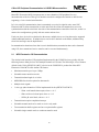
When the CSI peripheral is not used, the SCK, SO, and SI I/O pins can be used as port pins. The CSI
units are configured using mode registers, control registers, configuration registers, and dedicated
hardware logic.
Table 1. Description of Registers
Register Type
Control
Configuration
Configuration
Hardware Logic
Register Name
Symbol
Functional Description
CSI Mode (8-bit)
CSIM0n
Specifies CSI operation
Clock Selection
CSICn
Controls CSI serial transfer operation
Shift (8-, 16-bit)
SIO0n/SIO0nL
Converts parallel data to serial data
Receive Buffer (8-, 16-bit)
SIRBn/SIRBnL
Buffer register for receive data
Transmit Buffer (8-, 16-bit)
SOTBn/SOTBnL
Buffer register for transmit data
Initial Transmit Buffer
SOTBFn/SOTBFnL
Stores initial data in continuous transfer mode
Clock Select Logic
Selects the serial clock to be used
Serial Clock Counter
Controls the serial clock to the Shift Register
Interrupt Controller
Controls interrupt request timing
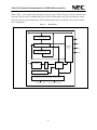
The CSI Mode register configures the CSI unit for:
•
Enabled or disabled operation
•
Receive-only mode or transmit and receive mode
•
8- or 16-bit data length
•
Most significant bit (MSB) or least significant bit (LSB) first
•
Single or continuous transfer
Clock selection and CSI transfer operation depends on:
•
Whether a positive or negative edge of the clock is used for the data capture strobe (clock polarity)
•
Whether the first edge of clock is used for the ata capture or data drive strobe (clock phase)
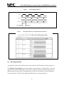
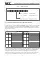
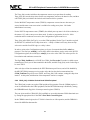
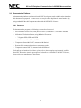
For example, the timing diagram shown in Figure 2 illustrates a positive-edge data capture, with the first
edge of clock used for data capture and the trailing edge for data drive strobe. See type 4 in Figure 3.
It is important to note that the master unit controls the serial clock. If the first edge of the serial clock is
used for the data capture strobe, the slave unit must be ready with data (driving data) before the first edge
of the serial clock. Typically, in this case, the Chip Select signal is used to indicate the start of
transmission from the master unit.
3
CSI to SPI Peripheral Communication in V850ES Microcontrollers
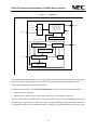
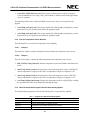
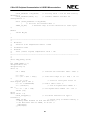
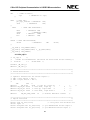
Figure 1.
CSI Operation
Freq/2 -to- 2**6
Timer Output
TM50
Serial Clock Control
Clock Star/Stop Control
Clock Phase Control
Serial Clock Counter
Interrupt Control
Clock
Selector
SCK0n_B
INTCSI0n
SCK0n_B
Transmission Control
Transmission Data Control
Control Signals
Initial Transmission
Buffer Register (SOTBFn)
SO Selection
SO0n
Transmission
Buffer Register (SOTBn)
SI0n
SO
Shift Register (SIO0n)
Latch
Receive Buffer Register
(SIRBn)
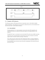
The second method of data transfer is to use the first edge of the serial clock as the data drive strobe and
the second edge for the data capture strobe. In this case, the first edge of the serial clock is used to
indicate start of transmission from the master unit.
For NEC Electronics MCUs, the Clock Selection Register, CSICn, specifies CSI transfer operation.
•
CKPn selects clock polarity.
•
DAPn specifies whether the first edge of the serial clock is data capture or data drive.
The slave unit, whether it is another MCU or a peripheral device such as a serial EEPROM, must provide
interface logic to support any one of the above type 1 through 4 clocking methods. The master unit must
be configured such that it can communicate with a certain type of clocking method used by the slave unit.
4
SCI to SPI Peripheral Communication in V850ES Microcontrollers
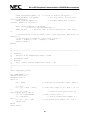
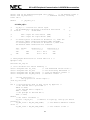
Figure 2.
Positive-Edge Data Capture
Clock
Data-In
Data Out
Data Capture Strobe
Master/Slave
Figure 3.
2.2
Data Drive Strobe
Master/Slave
Timing Specifications for Transmit and Receive Operations
SPI Communication
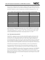
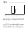
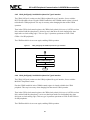
A typical MCU master with an SPI unit takes a form similar to NEC Electronics CSI units (Figure 4).
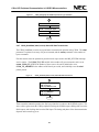
The SPI Mode Control Register specifies the transfer operation (Figure 5). When CPHA = 0, the first
edge of SCK is the data capture strobe for the first bit. Therefore, the slave unit must begin driving its
data before the first edge of SCK. The falling edge of SS_B (slave Chip Select) is used to indicate the
start of transmission. The SS_B must toggle high and then low between transmissions.
5
CSI to SPI Peripheral Communication in V850ES Microcontrollers
When CPHA = 1, the master begin driving data at the first edge of SCK. Therefore, the slave unit uses the
first edge of SCK as start of transmission signal. In this clocking mode, the SS_B can remain low (active
chip select state) between transmissions. This clocking method may be preferable for one master and one
slave configuration.
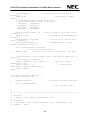
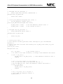
Figure 4.
SPI Operation
Internal Data Bus
Transmit Data Register
SI
SO
Shift Register
Input/Output
Control
Logic
Receive Data Register
SS_B
Clock
Clock Divider
Clock
Select
Clock Logic
Clock Control Logic
SPI Control Logic
Transmit/Receive Control, Mode Control, Interrupt Control
Transmit CPU Interrupt
SCK
Receive Error CPU Interrupt
6
SCI to SPI Peripheral Communication in V850ES Microcontrollers
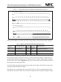
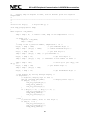
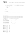
Figure 5.
7
6
5
4
CPOL
SPI Mode Control Register
3
2
1
0
CPHA
SPI Mode Control Register
2.3
CPHA = 0
First-edge of SCK
Falling-edge of SS_B
Used as Data Capture Strobe
Indicates Start of Transmission
CPHA = 1
First-edge of SCK
Slave-unit Uses
Used as Data Drive Strobe
First-edge of SCK as Start of Transmission
CPOL = 0
CPOL = 1
Idle-state of SCK = 0
Idle-state of SCK = 1
Rising-edge of SCK = Active-edge
Falling-edge of SCK = Active-edge
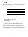
Comparison of NEC Electronics CSI and SPI Transfer Operations
The NEC Electronics CSI unit has a Clock Selection Register (CSICn), which specifies clocking method
using the CKPn and DAPn bits. The SPI unit has an SPI Control Register, which specifies clocking
method using the CPOL and CPHA bits. Table 2 shows a comparison of NEC Electronics CSI clocking
methods and those of the SPI.
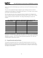
Table 2. CSI and SPI Clocking Methods
NEC Electronics CSI Clocking Method
SPI Clocking Method
CKPn
CPOL
DAPn
Clocking Type Descriptions
CPHA
Type 1 clocking method
0
0
Clocking Type Descriptions
Idle state clock = 1
Idle state clock = 1
1
1
First edge SCK is data drive strobe
First edge SCK is data drive strobe
Type 2 clocking method
0
1
Idle state clock = 1
Idle state clock = 1
1
0
First edge clock is data capture strobe
First edge clock is data capture strobe
Type 3 clocking method
1
0
Idle state clock = 0
Idle state clock = 0
0
1
First edge clock is data drive strobe
First edge clock is data drive strobe
Type 4 clocking method
1
1
Idle state clock = 0
Idle state clock = 0
0
0
First edge clock is data capture strobe
First edge clock is data capture strobe
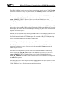
In both NEC Electronics CSI and SPI communication, when the first edge SCK is used as the data capture
strobe, Chip Select (SS_B) is used as a "start of transmission" signal. In this case, the Chip Select pin
should be driven inactive and then active again between data transmissions, as shown in Figure 6.
When the first edge SCK is used as the data drive strobe, the first edge SCK is the start of transmission
signal. In this case, the Chip Select pin can remain in the active state between data transmissions.
7
CSI to SPI Peripheral Communication in V850ES Microcontrollers
Figure 6.
Data-In
Data-Out
Byte - 1
Byte - 2
Chip Select
CPHA = 0
DAPn = 1
Chip Select
CPHA = 1
DAPn = 0
2.4
Examples of SPI Peripherals
The following examples of SPI peripherals show two temperature sensors, with similar but slightly
different SPI hardware. This application note will show how both of these devices can be interfaced to an
NEC Electronics MCU without additional hardware.
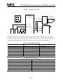
2.4.1 Maxim MAX6627
The Maxim MAX6627 is a remote temperature sensor with a built-in SPI-compatible serial
interface that connects to a remote diode-connected transistor for sensing temperature of the
transistor.
The MAX6627 sensor is a read-only slave device that has SCK (serial clock) and SDO (serial data
output) pins, but no serial data input pin. The SCK input is driven by the master unit; the SDO
output would be connected to the SI (serial input) of the master.
The CS (chip select) pin controls sensing and communication. When CS is high, the MAX6627
performs a temperature conversion once every second and stores the result internally. When CS is
low, the MAX6627 stops conversion, and is selected for communication. This means CS must be
driven by the master.
8
SCI to SPI Peripheral Communication in V850ES Microcontrollers
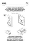
Figure 7.
Maxim MAX6627 Remote Temperature Sensor
2N3904
Diode-Connected
NPN-Type Transistor
The interface to the master unit expects SCK to be low when idle; for an SPI controller, this would
require CPOL=0. It uses the first edge of SCK as the data capture strobe and the trailing edge as the
data drive strobe; the first data drive strobe is the transition of CS from high to low. For an SPI
controller, this would require CPHA=0. This is equivalent to an NEC Electronics Type 4 CSI
interface.
SPI clocking method
CPOL = 0
CPHA = 0
NEC Electronics CSI clocking type
CKPn = 1
DAPn = 1
Type 4 interface
When the chip select line is activated, the first data bit is driven on SDO by the MAX6627, is
clocked into the MCU by the rising edge of SCK, and then the next data bit is driven on the falling
edge of SCK. Sixteen clocks drive sixteen bits of data, from D15 (MSB) to D0 (LSB). The data
contains the temperature reading as a signed value, with a sign bit (D15), twelve bits of
temperature data (D14 to D3), a zero bit (D2), and two bits not driven (D1 and D0).
9
CSI to SPI Peripheral Communication in V850ES Microcontrollers
The twelve bits of temperature data is in degrees centigrade, with the upper eight bits (D14 to D7)
indicating degrees, and the lower four bits (D6 to D3) indicating sixteenths of a degree. If the lower
three bits are masked to zero, the 16-bit signed value can be taken as (temperature in ºC) × 128.
Table 3. Examples of Binary, Hexadecimal, and Degree Representations of Temperature Data
Binary Temperature Data
Hexadecimal Temperature Data
Temperature (ºC)
0100 1000 1000 0000
4880H
145
0011 1100 0000 0000
3C00H
120
0011 0010 0000 0000
3200H
100
0001 1011 1000 0000
1B80H
55
0000 1010 0000 0000
0A00H
20
0000 0000 1000 0000
0080H
1
0000 0000 0000 1000
0008H
0.0625 (1/16)
0000 0000 0000 0000
0000H
0
1111 1111 1111 1000
FFF8H
–0.0625 (–1/16)
1111 1111 1000 0000
FF80H
–1
1111 0110 0000 0000
F600H
–20
1110 0100 1000 0000
E480H
–55
In this format, the maximum positive temperature value would be 7FF8H (0111 1111 1111 1000
binary), equivalent to +255.9375ºC. The maximum negative temperature value would be 8000H
(1000 0000 0000 0000 binary), equivalent to –256ºC. The device itself will not operate at these
extremes, and data from the remote sensor is only interpreted from –5 to +145ºC.
2.4.2 Dallas Semiconductor DS1722
The DS1722 is a temperature sensor device with a built-in SPI-compatible serial interface. This
read/write slave device has no remote transistor for temperature sensing; the temperature of the
device itself is read. A configuration register can be written, and the temperature high and low
bytes and configuration register can be read. The serial clock (SCLK) input is driven by the master
unit’s SCK signal; the serial data output (SDO) would be connected to the serial input (SI) of the
master unit, and the serial data input (SDI) is connected to the serial output (SO) of the master unit.
The DS1722 can do temperature conversions continuously, or one at a time, and then enter a
power-down mode (one-shot conversion). The conversion mode is controlled by a bit in the
configuration register. The latest temperature conversion is available for reading at any time.
The serial mode (SERMODE) and chip enable (CE) pins control communication. The SERMODE
pin selects the communication method; when high, SERMODE selects SPI mode. When CE is
high, the DS1722 temperature is enabled for communication and will respond to SCLK by reading
SDI and driving SDO; when CE is low, the DS1722 temperature sensor will ignore activity on the
SCLK, SDI, and SDO pins.
10
SCI to SPI Peripheral Communication in V850ES Microcontrollers
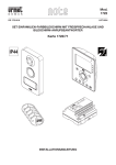
Figure 8.
MCU Connections to DS1722 Temperature Sensor
DS1722
SERMODE
CE
µC
SCLK
SDI
SDO
The polarity of the serial clock depends on its state when CE is asserted. Assuming SCLK is low when
CE goes high, the idle state of SCLK is low, which is equivalent to CPOL=0. If SCLK is high when CE
goes high, the idle state of SCLK is high, which is equivalent to CPOL=1.
For compatibility with the MAX6627, we will assume SCLK is low when idle (CPOL=0), and the first
edge of SCLK will be a rising edge. The interface to master unit uses the first edge of the serial clock as
the data drive strobe (when driving data to the master) and the trailing edge of serial clock as the data
capture strobe (when accepting data from the master). For an SPI controller, this would require CPHA=1,
which is equivalent to an NEC Electronics CSI type 3 interface.
NEC Electronics CSI clocking type
CKPn = 1
DAPn = 0
SPI clocking method
CPOL = 0
CPHA = 1
Type 3 interface
After CE is activated, the DS1722 sensor expects the master to transmit an address by sending eight bits
of data to SDI; during these eight bits, the SDO output will be in the high-impedance state, and the
DS1722 will clock in eight bits of address on the trailing edges of SCLK. Depending on the address, the
DS1722 will then drive SDO, ignoring further input on SDI (read operation from DS1722), or will
continue to read data on SDI and keep SDO in the high-impedance state (write operation to DS1722).
11
CSI to SPI Peripheral Communication in V850ES Microcontrollers
Figure 9.
Read and Write Cycles From the Master to the DS1722 Temperature Sensor
Write from Master to DS1722
Read from DS1722 to Master
Table 4 lists the addresses accepted by the DS1722 sensor and the action performed on those addresses.
Table 4. Addresses Accepted by the DS1722 Temperature Sensor
SDI first byte
(Address)
Second Byte Direction
Second
Byte SDI
Second
Byte SDO
Data Transferred
00H
Read from DS1722
Ignored
Driven
Configuration register Read
01H
Read from DS1722
Ignored
Driven
Temperature LSB (D15 to D8) read
02H
Read from DS1722
Ignored
Driven
Temperature MSB (D7 to D0) read
80H
Write to DS1722
Accepted
High-Z
Configuration register write
Read transfers from the DS1722 temperature sensor allow multiple registers to be read. The first written
byte specifies the address, and the first read byte will be the data from that address. If further bytes are
read, the address will be incremented once for each byte read. For example, if address 00H is specified,
the first read byte will be the Configuration register, the second read byte will be temperature LSB, and
third read byte will be temperature MSB.
To read all 16 bits of temperature data, the master would write the address 01H, and then read two bytes
(temperature LSB and temperature MSB).
The temperature is a 16-bit signed value, with a sign bit (D15), eleven bits of temperature data (D14 to
D4), and four zero bits (D3 to D0). The eleven bits of temperature data is in degrees Centigrade, with the
12
SCI to SPI Peripheral Communication in V850ES Microcontrollers
upper seven bits (D14 to D8) indicating degrees, and the lower four bits (D7 to D4) indicating sixteenths
of a degree.
The device can be programmed using the configuration register for different accuracies, from 8-bit
resolution (to the nearest degree) to 12-bit resolution (to the nearest 1/16th of a degree). Lower accuracies
provide faster conversion times between readings.
The 16-bit signed value can be taken as (temperature in degrees Centigrade) × 256. Examples of the
binary, hexadecimal, and degree representations of the temperature data are shown in Table 5. Note that
the data is different from that of the MAX6627. The reading of fractional degrees assumes 12-bit
resolution.
Table 5. Examples of Binary, Hexadecimal, and Degree Representations of Temperature Data
Binary Temperature Data
Hexadecimal Temperature Data
Temperature (ºC)
0111 1000 0000 0000
7800H
120
0110 0100 0000 0000
6400H
100
0011 0111 0000 0000
3700H
55
0001 0100 0000 0000
1400H
20
0000 0001 0000 0000
0100H
1
0000 0000 0001 0000
0010H
0.0625 (1/16)
0000 0000 0000 0000
0000H
0
1111 1111 1111 0000
FFF0H
–0.0625 (–1/16)
1111 1111 0000 0000
FF00H
–1
1110 1100 0000 0000
EC00H
–20
1100 1001 0000 0000
C900H
–55
In this format, the maximum positive temperature value would be 7FF0H (0111 1111 1111 0000 binary),
equivalent to +127.9375ºC. The maximum negative temperature value would be 8000H (1000 0000 0000
0000 binary), equivalent to –128ºC. The device itself is specified to operate from –55 to +120ºC and
would not be able to operate at these extremes.
2.5
Program Description and Specification
The program reads temperature data from two different SPI peripheral temperature sensor devices, a
MAX6627 and a DS1722, and displays the current temperature on the two-digit, seven-segment LED.
Pressing SW2 reads and displays the temperature from the MAX6627; pressing SW3 reads and displays
the temperature from the DS1722.
13
CSI to SPI Peripheral Communication in V850ES Microcontrollers
The V850ES MCU’s CSI peripheral is used for communication with the temperature sensor devices,
which have built-in SPI peripheral interfaces. For remote sensing of temperature, the MAX6627
temperature sensor uses a diode-connected NPN-type transistor that connects to the temperature-sensing
device through a twisted cable and senses the local temperature of the device.
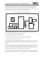
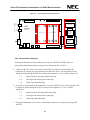
Figure 10.
NEC
V850ES-Series
Microcontroller
A
F
G
MAX6627 Diode-Connected NPN-Type Transistor
B
MAX6627
Port-Pin
E
/CS
Diode-Connected
NPN-Type Transistor
DxP
C
SDO
D
DP
SCK
LED-1 and LED-2
8-Bit
Output Port
8-Bit
Output Port
Port-Pin
CE
SO
SDI
SI
SDO
DxN
DS1722
SERMODE
VCC
Input Port Pin
LED-1
Input Port Pin
LED-2
SW2
SW3
SCK
SCLK
When interfacing with an SPI peripheral, it is necessary to configure the interface from the NEC
Electronics V850ES MCU using the clocked serial interface.
1. Determine the SPI peripheral clocking method used.
2. Configure the V850ES MCU’s CSI for the equivalent SPI clocking method.
3. Set appropriate registers for the selected CSI unit.
For the MAX6627, the SPI clocking method required is CPOL=0 (SCK idle state low), CPHA=0 (data
capture strobe on first clock edge). This requires an NEC Electronics CSI type 4 interface (CKPn=1,
DAPn=1).
For the DS1722, the SPI clocking method can have either CPOL=0 (SCK idle state low) if SCK is low
when CE is asserted, or CPOL=1 if SCK is high when CE is asserted. In either case, the clock phase
required is CPHA=1 (data driven on first clock edge, data capture strobe on clock trailing edge). If we
assume CPOL=0, this would require an NEC Electronics CSI type 3 interface.
Since NEC Electronics MCUs often have multiple CSI peripherals, it would be possible to connect the
MAX6627 to one set of CSI pins and the DS1722 to another set. However, since the NEC Electronics
14
SCI to SPI Peripheral Communication in V850ES Microcontrollers
CSI unit can be configured easily for one interface type or another, for this example, we connected the
two devices to the same pins, and switched from a type 3 interface (when reading the MAX6627) to a
type 4 interface (when reading the DS1722).
Two general-purpose I/O port pins are used to drive the MAX6627 Chip Select (/CS) and DS1722 Chip
Enable (CE) signals. Note that the /CS signal for the MAX6627 is active low, while the CE signal for the
DS1722 is active high.
Specifications
•
5 MHz crystal: 20 MHz system clock
•
CSI00: communication with temperature sensors
•
CSI00: 8-bit transmit and receive transfers, most significant bit (MSB) first
•
CSI00 clock: fxx/4, 5 MHz (max. for MAX6627 and DS1722)
•
Temperature data: signed 16-bit read data
•
Temperature data from the MAX6627: nearest 1/16th of a degree
•
DS1722: 10-bit accuracy (to the nearest 1/4th of a degree)
•
Temperature display: decimal data, scrolling through the LED digits
•
Timer TM00: periodic 1 millisecond (ms) interrupt for debouncing switches
2.6
Software Flowcharts
The demonstration program consists of the following major sections:
•
Initialization code for the program, called before the main() program starts, including clock and
peripheral initialization
•
The main program loop, which responds to switches by reading and reporting temperature
•
Subroutines for temperature reading and display
•
Subroutines for CSI00 peripheral access
•
Subroutines for reading switches and displaying data in LED
The flowcharts here will describe initialization, the main program, temperature routines, and CSI
peripheral access. Flowcharts are not included for timer access, switch reading, or the LED. The software
listings include this code.
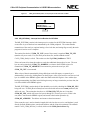
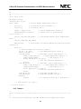
2.6.1 Program Startup and Initialization
For V850ES programs written in C language, the startup code for the C program is supplied by an
assembly language startup file, generally named crte.s. This startup code specifies the reset vector,
15
CSI to SPI Peripheral Communication in V850ES Microcontrollers
which determines where the program will begin on a hardware reset and provides initial setup of
system registers before calling the main() function.
When Applilet is used to generate a C program for the V850ES MCU, the crte.s startup assembly
language file is automatically generated, and includes a call to the Clock_Init() function to set the
system clock, and a call to the SystemInit() function which in turn calls initialization routines for
some (but not all) peripherals.
Figure 11.
crte.s Startup File
RESET
Crte.s
Clock_Init( )
System Register Init
Set PCC and PLL
CALL Clock_Init( )
other initialization
SystemInit( )
CALL SystemInit( )
CALL Port_Init( )
CALL TM00_Init( )
CALL main( )
A
After the SystemInit() function finishes, the startup code calls the main() function of the user program.
So at the start of the main() function, peripheral initialization has been done for several peripherals. The
main() function does not need to call these individual peripheral initialization routines.
Note that SystemInit() does NOT automatically call the CSI00_Init() routine to initialize the CSI00
peripheral.
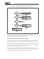
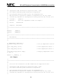
2.6.2 Main( ): Main Program for NEC Electronics CSI to SPI Serial Communication
The main( ) program is called from the startup code after peripheral initialization. The program
calls routines to initialize input switch handling and LED output.
16
SCI to SPI Peripheral Communication in V850ES Microcontrollers
Main( ) then calls Temp_Init( ) to initialize the temperature sensors and the CSI/SPI interface used
to communicate with the sensors. If an error is detected, an error code is displayed and the program
enters an endless loop.
To indicate proper initialization, a pair of dashes is shown in the LED. TM00_Start( ) is called to
start the TM00 timer for a periodic 1 millisecond interrupt, used for debouncing the input switches.
The main( ) program then enters the main program loop. The program checks the state of the SW2
and SW3 switches for the action to perform.
Figure 12.
Main( ): Main Program for NEC Electronics CSI to SPI Serial Communication
A
Initialize switches and LED display
B
CALL Temp_Init( )
Display “- -” in LED display
CALL TM00_Start( ) to debounce
Get state of SW2 and SW3
SW2 only?
Yes
No
SW3 only?
temp = Temp_Read_1( )
CALL Temp_Display(temp)
Wait for switches different
Yes
Temp = Temp_Read_2( )
C
E
D
No
CALL Temp_Display(temp)
Wait for switches different
E
If SW2 is pressed, the MAX6627 temperature sensor is read by calling Temp_Read_1( ), and the
variable temp is set to the value read. The temperature is then displayed in the LED by calling
Temp_Display(temp). Main() then waits for the switch state to be different.
If SW3 is pressed, the DS1722 temperature sensor is ready by calling Temp_Read_2( ), setting
temp to the value read. The temperature is then displayed in the LED by calling
Temp_Display(temp). Main() then waits for the switch state to be different.
17
CSI to SPI Peripheral Communication in V850ES Microcontrollers
After processing the switches, main() returns to the top of the program loop to check switch states
again.
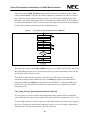
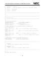
2.6.3 Temp_Init(): Initialize Temperature Sensor Interface
The Temp_Init() routine initializes the temperature sensors to prepare them for reading.
Temp_Init() first sets the chip selects for the two temperature sensors to the inactive state, and then
calls CSI00_Init() to initialize the clocked serial interface 00 for operation.
For the MAX6627 temperature sensor (TEMP1), temperature conversions are done once per
second, and the most recent conversion is available for reading at any time. No further initialization
is necessary.
For the DS1722 temperature sensor (TEMP2), the default power-up state is for 8-bit resolution (to
the nearest 1ºC), and to enter power-down mode. To program the device for 10-bit resolution and
for continuous conversion, the Configuration register must be set.
Figure 13.
Temp_Init(): Initialize Temperature Sensor Interface
B
TEMP1_CS_OFF (P9H.7 = 1)
TEMP2_CS_OFF (P9H.6 = 0)
C
CALL CSI00_Init( )
D
CALL CSI00_SetType3( )
TEMP2_CS_ON (P9H.6 = 1)
Delay 400ns from CS on
txbuf[0] = 0x80
txbuf[1] = 0xE4
CSI00_SendDone = FALSE
CALL CSI00_SendData(txbuf, 2)
SendDone
== FALSE?
No
TEMP2_CS_OFF (P9H.6 = 0)
Return
18
Yes
F
SCI to SPI Peripheral Communication in V850ES Microcontrollers
The Temp_Init() routine initializes the temperature sensors to prepare them for reading.
Temp_Init() first sets the chip selects for the two temperature sensors to the inactive state, and then
calls CSI00_Init() to initialize the clocked serial interface 00 for operation.
For the MAX6627 temperature sensor (TEMP1), temperature conversions are done once per
second, and the most recent conversion is available for reading at any time. No further
initialization is necessary.
For the DS1722 temperature sensor (TEMP2), the default power-up state is for 8-bit resolution (to
the nearest 1ºC), and to enter power-down mode. In order to program the device for 10-bit
resolution and for continuous conversion, the Configuration register must be set.
Temp_Init() calls CSI00_SetType3( ) to set the CSI00 peripheral for the Type-3 interface required
for the DS1722, and then sets its chip select active. A delay of 400ns is necessary between chip
select active and the first SCK edge, so a delay is done.
In order to write to the Configuration register, two bytes of a transmit data buffer, txbuf, are
prepared. The first byte, txbuf[0], is set to 80H, which is the address used to write to the DS1722
Configuration register, the second byte, txbuf[1], is set to the value E4H. This value specifies 10bit resolution and continuous conversion.
The flag CSI00_SendDone is set FALSE, the CSI00_SendData(txbuf, 2) routine is called to start
transmission of two bytes of data contained in the buffer, and then Temp_Init() waits for the flag to
be set to TRUE.
After each byte of data is transmitted, the INTCSI00 interrupt will occur, and will be handled by
the MD_INTCSI00() interrupt service routine. After the last byte has been transmitted, the
CSI00_SendDone flag will be set to TRUE, and Temp_Init() will continue, setting the chip select
inactive. At this point, initialization of the temperature sensors is complete.
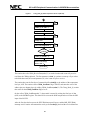
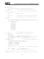
2.6.4 CSI00_Init(): Initialize Clocked Serial I/O 00 Peripheral
The CSI00_Init() routine sets up the CSI00 peripheral for operation. First the CSIM00 register is
set to 00, which disables the CSI00 peripheral, and the INTCSI00 interrupt is disabled by setting
the CSK0MK0 mask flag (bit 6 of interrupt control register CSI0IC0).
The port 4 pins used for CSI00 (P42, P41, and P40) are set to their alternate CSI00 functional uses
by setting the appropriate bits in the PMC4 Port Mode Control Register.
In the CSIM00 control register, the CCL0 bit is cleared to set 8-bit operation, and the DIR0 bit is
cleared for MSB-first data transfer.
19
CSI to SPI Peripheral Communication in V850ES Microcontrollers
In the CSIC0 clock control register, the CKP0 (clock polarity) bit is set to one and the DAP0 (data
phase) bit is cleared to zero. This sets type 3 operation, equivalent to CPOL=0 and CPHA=1 for
SPI peripherals. Note that this will be changed by the CSI00_SetType4() routine, and restored by
the CSI00_SetType3() routine, to change modes depending on which SPI peripheral is accessed.
Figure 14.
CSI00_Init(): Initialize Clocked Serial I/O 00 Peripheral
C
CSIM00 = 00H to disable CSI00
CSI0MK0 = 1 (CSI0IC0.6) mask int
PMC4.2-0 = 111
P42 pin set to SCK00 function
P41 pin set to SO00 function
P40 pin set to SI00 function
CCL0 = 0 (CSIM00.5) for 8-bit
DIR0 = 0 (CSIM00.4) for MSB first
CKP0 = 1 (CSIC0.4)
DAP0 = 0 (CSIC0.3) for Type-3
CKS002 – CKS000 = 001
(CSIC0.2-0) for fxx/4, 5 MHz
CSI0IC0.2-0 = 111 for lowest priority
CSI0MK0 = 0 (CSI0IC.5) enable int
TRMD0 = 1 (CSIM0.6) for Tx/Rx
CSI0E0 = 1 (CSIM0.7) to enable
Return
The lowest three bits of the CSIC0 clock control register set the clock to be used for the CSI00
peripheral. These are set to 001, to select the clock as fxx/4. Since the system clock is 20 MHz, this
setting produces a SCK frequency of 5 MHz, the maximum supported for the two peripherals used.
The interrupt control register CSI0IC0 is set for the lowest priority group, and the INTCSI00
interrupt is enabled by clearing the mask bit CSI0MK0.
In the CSIM0 control register, the TRMD0 bit is set to one to allow transmit/receive operation, and
finally the CSI0E0 enable bit is set to enable the CSI00 peripheral to operate.
At this point, the CSI00 peripheral is ready for operation. Writing a byte to the SOTB0L register
will begin data transmission and simultaneous reception.
20
SCI to SPI Peripheral Communication in V850ES Microcontrollers
2.6.5 CSI00_SetType3(): Set CSI00 Peripheral for Type 3 Interface
The CSI00_SetType3() routine sets the CSI00 peripheral for type 3 interface, for use with the
DS1722 temperature sensor. First the CSI0E0 enable bit in the CSIM00 control register is cleared
to disable the CSI00 peripheral. This step is necessary when changing bits that control CSI00
operation.
Then in the CSIC0 clock control registers, the CKP0 (clock polarity) bit is set to 1 (SCK low when
idle), and the DAP0 bit (data phase) is cleared to zero (data driven on clock leading edge, data
input strobe on clock trailing edge). This sets Type-3 operation, equivalent to CPOL=0 and
CPHA=1 for SPI peripherals.
The CSI0E0 enable bit is set to one again, enabling CSI00 operation.
Figure 15.
CSI00_SetType3(): Set CSI00 Peripheral for Type 3 Interface
D
CSI0E0 = 0 (CSIM00.7) to disable
CKP0 = 1 (CSIC0.4)
DAP0 = 0 (CSIC0.3) for Type-3
CSI0E0 = 1 (CSIM00.7) to enable
Return
2.6.6 CSI00_SetType4(): Set CSI00 Peripheral for Type 4 Interface
The CSI00_SetType4() routine sets the CSI00 peripheral for type 4 interface, for use with the
MAX6627 temperature sensor.
First the CSI0E0 enable bit in the CSIM00 control register is cleared to disable the CSI00
peripheral. This step is necessary when changing bits that control CSI00 operation.
Then in the CSIC0 clock control registers, the CKP0 (clock polarity) bit is set to 1 (SCK low when
idle), and the DAP0 bit (data phase) is set to one (data input strobe on clock leading edge, data
driven out on clock trailing edge). This sets type 4 operation, equivalent to CPOL=0 and CPHA=0
for SPI peripherals.
The CSI0E0 enable bit is set to one again, enabling CSI00 operation.
21
CSI to SPI Peripheral Communication in V850ES Microcontrollers
Figure 16.
CSI00_SetType4(): Set CSI00 Peripheral for Type 4 Interface
E
CSI0E0 = 0 (CSIM00.7) to disable
CKP0 = 1 (CSIC0.4)
DAP0 = 1 (CSIC0.3) for Type-4
CSI0E0 = 1 (CSIM00.7) to enable
Return
2.6.7 CSI00_SendData(*txbuf, txnum): Start CSI Data Transmission
The CSI00_SendData() routine sets up and starts a transmission operation using CSI00. The txbuf
parameter is a pointer to an array of bytes to transmit, and the txnum parameter is the number of
bytes to transmit.
First the routine stores the parameters passed in local copies used in the MD_INTCSI00 interrupt
service routine. The CSI00_TX_LEN variable is the number of bytes to transmit, and is set to
txnum; CSI00_TX_CNT is the number of bytes sent so far, and is initialized to zero;
CSI00_TX_ADDRESS is the address of the next byte to send, and is initially set to the txbuf
pointer passed.
Figure 17.
CSI00_SendData(*txbuf, txnum): Start CSI Data Transmission
F
CSI00_TX_LEN = txnum
CSI00_TX_CNT = 0
CSI00_TX_ADDRESS = txbuf
SOTB0L = *CSI00_TX_ADDRESS
CSI00_TX_ADDRESS ++
CSI00_TX_CNT ++
Return
Then to start the transmit operation, the first byte pointed to is written to the SOTB0L register. The
write to this register starts the CSI00 peripheral clocking the SCK00 output, shifting data out on the
SO00 output, and clocking data in on the SI00 input. The timing and phase of the data transmission
depends on the transfer type set.
22
SCI to SPI Peripheral Communication in V850ES Microcontrollers
The CSI00_SendData() routine sets up and starts a transmission operation using CSI00. The txbuf
parameter is a pointer to an array of bytes to transmit, and the txnum parameter is the number of
bytes to transmit.
First the routine stores the parameters passed in local copies used in the MD_INTCSI00 interrupt
service routine. The CSI00_TX_LEN variable is the number of bytes to transmit, and is set to
txnum; CSI00_TX_CNT is the number of bytes sent so far, and is initialized to zero;
CSI00_TX_ADDRESS is the address of the next byte to send, and is initially set to the txbuf
pointer passed.
Then to start the transmit operation, the first byte pointed to is written to the SOTB0L register. The
write to this register starts the CSI00 peripheral clocking the SCK00 output, shifting data out on the
SO00 output, and clocking data in on the SI00 input. The timing and phase of the data transmission
depends on the transfer type set.
After the first byte is written to the transmit register, the pointer is incremented to point to the next
byte, and the count is incremented (to one). The routine returns at this point. When the first byte
has finished transmission, the INTCSI00 interrupt will occur, and the MD_INTCSI00() interrupt
service routine will handle further transmission and reception.
2.6.8 CSI00_ReceiveData(*rxbuf, rxnum): Prepare To Receive Data on CSI00
The CSI00_ReceiveData() routine sets up for data to be received using CSI00. The rxbuf
parameter is a pointer to an array of bytes to receive the data, and the rxnum parameter is the
number of bytes to receive.
The routine stores the parameters passed in local copies used in the MD_INTCSI00 interrupt
service routine. The CSI00_RX_LEN variable is the number of bytes to receive, and is set to
rxnum; CSI00_RX_CNT is the number of bytes received so far, and is initialized to zero;
CSI00_RX_ADDRESS is the address of the next byte to store received data, and is initially set to
the txbuf pointer passed.
The routine then returns without any access to the CSI00 peripheral. The values set will be used in
the MD_INTCSI00() interrupt service routine when INTCSI00 occurs. To have the interrupt occur,
CSI00_SendData() must be called to start a transmission operation.
23
CSI to SPI Peripheral Communication in V850ES Microcontrollers
Figure 18.
CSI00_ReceiveData(*rxbuf, rxnum): Prepare To Receive Data on CSI00
G
CSI00_RX_LEN = rxnum
CSI00_RX_CNT = 0
CSI00_RX_ADDRESS = rxbuf
Return
2.6.9 MD_INTCSI00() : Interrupt Service Routine for INTCSI00
The MD_INTCSI00() routine is the interrupt service routine for the INTCSI00 interrupt, which
occurs after a byte of data has been transmitted by the CSI00 peripheral. The routine handles
transmission of the next byte, optional storing of received data, and setting flags to notify the main
program of send or receive complete.
The routine first checks if CSI00_TX_CNT (count of bytes sent) is equal to CSI00_TX_LEN
(number of bytes to send). If so, the last byte has been sent, and the callback routine
CALL_CSI00_Send() is called. This routine sets the flag CSI00_SendDone to TRUE.
If the send count is less than the number to send, then additional data needs to be sent. The next
byte to send, pointed to by CSI00_TX_ADDRESS, is written to the SOTB0L register for
transmission; CSI00_TX_ADDRESS is incremented to point to the next byte, and
CSI00_TX_CNT is incremented.
When a byte of data is transmitted by being shifted out on the SO output, a separate byte is
simultaneously received by shifting data in on the SI input. After a byte has been sent, the received
byte is available in the SIRB0L register and in the SI000 serial shift register. Once another byte
has begun transmitting, the SI000 serial shift register may no longer contain the previous data, but
it is still available in the SIRB0L register.
The MD_INTCSI00() routine checks if data should be received by checking for CSI00_RX_LEN
being non-zero. If CSI00_ReceiveData() has been called with an non-zero rxnum parameter, this
will be the case. The routine then checks to see if CSI00_RX_CNT plus one is less than
CSI00_RX_LEN, which will be true for bytes 0 through n-1 of an n-byte receive. If this is the
case, data is read from the SIRB0L register, and stored at the location pointed to by
CSI00_RX_ADDRESS. The address and count are then incremented.
If the count plus one is not less than the length, this is the last byte to receive, and the data is read
directly from the SI000 register, stored at the address, and the count is incremented. The callback
routine CALL_CSI00_Receive() is called, which sets the CSI00_ReceiveDone flag.
24
SCI to SPI Peripheral Communication in V850ES Microcontrollers
Figure 19.
MD_INTCSI00() : Interrupt Service Routine for INTCSI00
INTCSI00
TX_CNT ==
TX_LEN?
Yes
CALL CALL_CSI00_Send( )
Yes
SOTB0L = *CSI00_TX_ADDRESS
CSI00_TX_ADDRESS ++
CSI00_TX_CNT ++
No
TX_CNT <
TX_LEN?
No
RX_LEN == 0?
Yes
Return
No
RX_CNT + 1
< RX_LEN?
Yes
*CSI00_RX_ADDRESS = SIRB0L
CSI00_RX_ADDRESS ++
CSI00_RX_CNT ++
No
Return
*CSI00_RX_ADDRESS = SI000
CSI00_RX_CNT ++
CALL CALL_CSI00_Receive( )
Return
After processing transmit data and optional received data, the MD_INTCSI00() routine returns to
the program at the place where the INTCSI00 interrupt occurred.
2.6.10 Temp_Read_1(): Read Temperature Sensor 1 (MAX6627)
The Temp_Read_1() routine reads the latest temperature reading from the MAX6627 temperature
sensor, and returns the value read as a signed 16-bit value, equivalent to (temperature in ºC) × 128.
First the CSI00_SetType4() routine is called, to set the CSI00 transfer type to the proper setting for
this device. Then the chip select for the temperature sensor is set on (active low). A short delay is
inserted to allow 100ns from chip select to the first serial clock.
The routine then calls CSI00_ReceiveData(rxbuf, 2) to set the location and count of bytes to be
read from the CSI00 peripheral. The first parameter, rxbuf, is a pointer to an array of byte values
to hold the data read; the second parameter, 2, is the count of bytes to receive.
25
CSI to SPI Peripheral Communication in V850ES Microcontrollers
The routine sets the CSI00_SendDone flag to FALSE, and writes two dummy bytes by calling
CSI00_SendData(txbuf, 2). Because the CSI00 peripheral is in transmit/receive mode, in order to
receive data, the transfer must be started by writing a byte of data to the SOTB0L register. This
data will be sent out the SO00 output, which is not connected to the MAX6627; the first eight bits
of data from the MAX6627 will be clocked in on the SI00 input. Reception of the second eight bits
of data is done during the transmission of the second dummy byte.
Figure 20.
Temp_Read_1(): Read Temperature Sensor 1 (MAX6627)
H
E
CALL CSI00_SetType4( )
TEMP1_CS_ON (P9H.7 = 0)
Delay 100ns after CS active
G
CALL CSI00_ReceiveData(rxbuf, 2)
CSI00_SendDone = FALSE
CALL CSI00_SendData(txbuf, 2)
SendDone
== FALSE?
F
Yes
No
TEMP1_CS_OFF (P9H.7 = 1)
retval = rxbuf[0] << 8
retval = retval | (rxbuf[1] & 0xF8)
Return retval
The routine then waits for the CSI00_SendDone flag to be set to TRUE, which will be done by the
MD_INTCSI00() interrupt service routine after the last byte of data is transmitted, which will also
have clocked in the last byte to receive.
Temp_Read_1() then sets the temperature sensor chip select off, to have the sensor resume
temperature readings. It then combines the bytes in rxbuf[0] (first eight bits from MAX6627 =
Temperature MSB), and rxbuf[1] (second eight bits from MAX6627 = temperature LSB) into a
signed 16-bit value. It masks the lowest three bits, and returns the 16-bit signed value, which is
temperature × 128.
2.6.11 Temp_Read_2(): Read Temperature Sensor 2 (DS1722)
The Temp_Read_1() routine reads the latest temperature reading from the DS1722 temperature
sensor, and returns the value read as a signed 16-bit value, equivalent to (temperature in ºC) × 128.
First the CSI00_SetType3() routine is called, to set the CSI00 transfer type to the proper setting for
this device. Then the chip select for the temperature sensor is set on (active high). A short delay is
inserted to allow 400 ns from chip select to the first serial clock.
26
SCI to SPI Peripheral Communication in V850ES Microcontrollers
Figure 21.
Temp_Read_2(): Read Temperature Sensor 2 (DS1722)
I
D
CALL CSI00_SetType3( )
TEMP2_CS_ON (P9H.6 = 1)
Delay 100ns after CS active
G
CALL CSI00_ReceiveData(rxbuf, 3)
txbuf[0] = 0x01
CSI00_SendDone = FALSE
CALL CSI00_SendData(txbuf, 3)
SendDone
== FALSE?
F
Yes
No
TEMP2_CS_OFF (P9H.6 = 0)
Retval = rxbuf[2] << 8
Retval = retval | rxbuf[1]
Retval = retval / 2
Return retval
The routine then calls CSI00_ReceiveData(rxbuf, 3) to set the location and count of bytes to be
read from the CSI00 peripheral. The first parameter, rxbuf, is a pointer to an array of byte values
to hold the data read; the second parameter, 3, is the count of bytes to receive.
The routine then sets the first byte of a transmit buffer, txbuf[0], to the address of the temperature
low byte, 01H. The routine sets the CSI00_SendDone flag to FALSE, and starts the write of the
address plus two dummy bytes by calling CSI00_SendData(txbuf, 3). The Temp_Read_2() routine
then waits for the CSI00_SendDone flag to be set.
On the call to CSI00_SendData(txbuf, 3), the transfer is started by writing the first byte of data
(01H) to the SOTB0L register. This data will be sent out the SO00 output and received at the SDI
input of the DS1722.
After the first byte has been sent, the INTCSI00 interrupt will occur, and the MD_INTCSI00()
interrupt service routine will transmit the next byte from txbuf[1], and read the received data into
27
CSI to SPI Peripheral Communication in V850ES Microcontrollers
the rxbuf[0] location. The first received data will not have been driven by the DS1722, so this first
receive byte does not contain temperature data.
While the dummy data in txbuf[1] is transmitted, the DS1722 will drive the Temperature low byte
out on its SDO pin, and this data will be clocked in on SI00.
After the second byte has been sent, INTCSI00 will occur, and MD_INTCSI00() will transmit
txbuf[2] and read the received temperature low byte into rxbuf[1]. While the dummy data in
txbuf[2] is transmitted, the DS1722 will have advanced its address to 02H, and will drive the
Temperature high byte data out on SDO.
After the third and final byte has been sent, INTCSI00 will occur again, and MD_INTCSI00() will
set the CSI00_SendDone flag, store the last received byte of data (temperature high byte) into
rxbuf[2].
At this point, Temp_Read_2() will see the flag as true, and set the temperature sensor chip select
off, to have the sensor resume temperature readings. It then combines the bytes in rxbuf[1] (first
eight bits from DS1722 = Temperature low byte), and rxbuf[2] (second eight bits from DS1722 =
Temperature high byte) into a signed 16-bit value. In the 10-bit data resolution selected for the
DS1722, this will be (temperature in ºC) × 256, to the nearest 1/4th degree.
To return a temperature value in the same scale as Temp_Read_1(), Temp_Read_2() divides the
signed 16-bit data by two, resulting in (temperature in ºC) × 128, and returns this value.
2.6.12 Temp_Display(temp): Show Temperature in LED
The Temp_Display() routine displays the temperature data in the two-digit LED, by scrolling the
data through the LED digits. The temp parameter is a signed 16-bit value, of temperature × 128.
The routine will display digits in the format of (sign)XXX.YY.
Since the details of this routine have nothing to do with the CSI/SPI interface, the flowchart for this
routine is not shown. A description of the display format follows. For those interested in the
mechanics of the routine, please see the listing in Section 4.
If the temperature is negative, a dash will precede the number for a minus sign, otherwise no sign
will be shown.
28
SCI to SPI Peripheral Communication in V850ES Microcontrollers
The data will be shown serially in the two LED digits, scrolling the number through with short
delays between shifts. For example the temperature +123.75ºC would be shown as:
“1 2”
hundreds and tens digits
“2 3.”
tens and units digits, with decimal point
“3. 7”
units digit with decimal point, tenths digit
“7 5”
tenths digit, hundredths digit
The temperature –43.275ºC would be shown as
“4 ”
minus sign, tens digits
“4 3.”
tens digit, units digits with decimal point
“3. 2”
units digit with decimal point, tenths digit
“5 7”
tenths digit, hundredths digit (fraction after hundredths truncated)
If the number is such that –100 < temp < +100, no hundreds digit will be shown. If the number is
such that –10 < temp < +10, no tens digit will be shown, and a blank or the sign will be displayed.
The temperature +5.00ºC would be shown as:
“
5.”
blank tens digit, units digit with decimal point
“5. 0”
units digit with decimal point, tenths digit
“0 0”
tenths digit, hundredths digit
The temperature of ±5.00ºC would be shown as:
2.7
“– 5.”
minus sign, units digit with decimal point
“5. 0”
units digit with decimal point, tenths digit
“0 0”
tenths digit, hundredths digit
Applilet's Reference Driver
NEC Electronics’ Applilet program generator can automatically generate C or assembly language source
code to manage peripherals for the NEC Electronics MCUs. See Section 3 for the version of Applilet
used.
Applilet is used to produce the basic initialization code and main function for the program, clock
initialization code, initialization and driver code for the CSI00 and timer TM00 peripherals, and
29
CSI to SPI Peripheral Communication in V850ES Microcontrollers
initialization for I/O ports used. After Applilet produces the basic code, additional code is added by the
user to customize the functioning of the program.
This section describes how Applilet is set up to produce code for these peripherals, and lists the files and
routines produced. Additional files not generated by Applilet, such as those written for temperature
sensor access, are also listed.
Applilet is started, and a new project file is created and saved as a .prx file. Applilet shows a screen
allowing different peripheral blocks to be selected for setup.
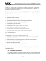
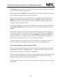
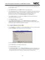
2.7.1 Configuring Applilet for Clock Initialization
1. In the System box, click the Foundation setting tab to select the clocks to be initialized in the
Clock_Init() routine.
Figure 22.
System Box
2. Select Main clock operation to operate on the external crystal
3. Select PLL function On to set the clock to use the PLL multiplier.
4. In the Oscillates setting box, set the Main oscillator at 5 MHz. With the PLL on, this results
in a system clock of 20 MHz.
5. Select Ring-OSC option byte selection box, select Ring-OSC can be stop by software. If
this option is not selected, the watchdog timer 2 (WDTM2) cannot be stopped and would
reset the program periodically if not disabled or cleared within a certain time interval. In
order to make the program code clearer, the watchdog timer is not used.
30
SCI to SPI Peripheral Communication in V850ES Microcontrollers
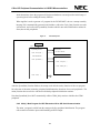
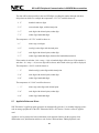
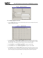
2.7.2 Configuring Applilet for CSI00
1. In the Serial Communication Interface box, select CSI00 to open the CSI00 tab.
Figure 23.
Serial Communication Interface Box
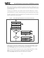
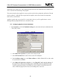
2. The CSI00 tab enables you to control the code generated for the CSI00_Init() routine, and for
routines used to read and write data.
Figure 24.
CSI00 Tab
3. In the Transfer mode box, select Receive/Transmit mode, since the DS1722 temperature
sensor requires output in order to be configured or read.
4. The MAX6627 temperature sensor provides its temperature data as a 16-bit value; the DS1722
temperature sensor requires an 8-bit output, and provides the temperature as two 8-bit values.
Therefore, in the Data length box, select 8 bits to write data and to read the temperature data
31
CSI to SPI Peripheral Communication in V850ES Microcontrollers
in two 8-bit cycles. If the MAX6627 sensor were the only device used, you would need to set
the data length to 16 bits.
5. In the Data direction box, select MSB to match the temperature sensors.
6. The two temperature sensors use different clock types. The MAX6627 uses a type 4 (clock data
mode4), and the DS1722 a type 3 (clock data mode3). To manage changing between one type
and another, the routines CSI00_SetType3() and CSI_SetType4() were written. For
initialization in this example, select clock data mode3 in the Clock mode box.
7. In the Transfer speed box, set the baud rate to 5 Mbps to match the maximum data rate
supported by the temperature sensors.
8. In the Interrupt setting box, select lowest.
9. In the Callback function setting box, select Callback function for reception end and
Callback function for transmission end to provide a mechanism to notify the main program
when a data reception or transmission operation is complete.
2.7.3 Configuring Applilet for Timer 00 (TM00)
1. On the Timer00 tab in the Timer box, select the Interval timer to provide a periodic interrupt,
and then click Detail to set the details of the Timer 00 interval timer.
Figure 25.
Timer00 Tab in the Timer Box
2. In the Count clock box, select fxx/2 to use a 10 MHz clock for the timer.
3. In the Value scale box, select msec for milliseconds.
4. In the Interval timer box, enter 1.
5. In the Interrupt setting box, select TM00 and CR000 match, generate an interrupt so that
Timer 00 will generate an interrupt every millisecond. This interrupt is used for debouncing
the pushbutton switches and to count down a millisecond timer for timing delays.
32
SCI to SPI Peripheral Communication in V850ES Microcontrollers
Figure 26.
TM00 Interval Timer Box
2.7.4 Configuring Applilet for I/O Ports
1. Open the Digital I/O Port box to set the individual port pins for input or output, and to specify
settings for the pull-up resistors.
Figure 27.
Digital I/O Port Box
2. On the Port 9-2 tab, set P914 and P915 as outputs. These pins are used as the chip selects for
the temperature sensor. (In the program, when these bits are accessed, the reference is to P9H.6
(P914) and P9H.7. The upper byte of the 16-bit port 9 can be referenced as P9H.)
3. On the PortDH tab, set ports PDH0 through PDH7 as outputs to control LED1.
4. On the PortDL-2 tab, set ports PDL8 through PDL15 as outputs to control LED2.
5. On the Port9-1 tab, set ports P94 and P95 as inputs, and also select pull-up resistors for use for
these pins. These ports are connected to switches SW2 and SW3, which ground the input when
pressed. The pull-up resistor option holds these inputs high when the switch is not pressed.
33
CSI to SPI Peripheral Communication in V850ES Microcontrollers
2.7.5 Generating Code With Applilet
Once the various dialog boxes are set up, select the “Generate code” option. Applilet will show the
peripherals and functions to be generated, and allows you to select a directory to store the source
code.
When the “Generate” button is pressed, Applilet creates the code in several C-language source files
(extension .c), C header files (extension .h), and assembly language source and header files
(extensions .s and .inc), and shows the list of files created in a dialog box.
To support the initial startup code, Applilet generates assembly source file crte.s. For clock
initialization, Applilet generates system.inc and system.s. The SystemInit() function is generated in
systeminit.c.
To support the CSI00 peripheral, Applilet generates serial.h, serial.c, and serial_user.c. See details
on these files below.
To support the Timer00 peripheral, Applilet generates timer.h, timer.c and timer_user.c.
To support I/O port initialization, Applilet generates port.h and port.c.
Several other files are generated, including a main.c file with a blank main function. Applilet also
generates a link directive file, 850.dir, to control the linking process.
2.7.6 Applilet-Generated Files
For the demonstration program, Applilet generated several source files. The files and their
functions are shown below.
Table 6. Applilet-Generated Source File
File
Function
Macrodriver.h
General header file for Applilet-generated programs
Crte.s
Reset vector, program startup code
System.inc
Assembly-language header for system.s
System.s
Assembly source for Clock_Init() routine
System_user.s
Empty file (would contain code for System interrupt if used)
Systeminit.c
SystemInit() routine for peripheral initialization
Main.c
The main program routine
Inttab.s
Interrupt vectors with RETI for unused interrupts
Port.h
Header file defining initial port states
Port.c
Port_Init() routine
Serial.h
Header file for serial.c
Serial.c
CSI00 functions generated by Applilet
Serial_user.c
Callback functions for UART1 and CSI00, for user code
34
SCI to SPI Peripheral Communication in V850ES Microcontrollers
File
Function
Timer.h
Header file for timer.c
Timer.c
Timer 00 functions
Timer_user.c
User code for INTTM000 interrupt
850.dir
Link directive file
2.7.7 Applilet-Generated Files for CSI00 Operation
The code generated for CSI00 support are in the files serial.h, serial.c, and serial_user.c. These
contain the following items.
2.7.7.1
Serial.h
The header file serial.h contains definitions for the CSI00 functions. The header file macrodriver.h,
used for all Applilet generated code, also defines some data types and values, such as the
MD_STATUS values returned by some functions.
2.7.7.2
Serial.c
The source file serial.c contains the following functions generated by Applilet:
1. void CSI00_Init( void ): Initializes the CSI00 peripheral as specified in the Applilet CSI00
dialog;
2. MD_STATUS CSI00_SendData( UCHAR* txbuf, UCHAR txnum ): Sets up a transmit
operation of txnum characters from the txbuf buffer; will also start the transmission operation
by sending the first byte to the SOTB0L register
3. MD_STATUS CSI00_ReceiveData( UCHAR* rxbuf, UCHAR rxnum ): Sets up a receive
operation, requesting rxnum characters be received to the rxbuf buffer. This routine does not
start a CSI00 transfer operation; reception is started by calling CSI00_SendData() to send
bytes.
4. __interrupt void MD_INTCSI00( void ): The interrupt service routine for the CSI00 interrupt
INTCSI00. For transmit operations, sends the next data and increments the count; when done,
calls the CALL_CSI00_Send() callback routine. For receive operations, stores the received
data to the receive buffer and increments the count.
2.7.7.3
Serial_user.c
The source file serial_user.c contains stub functions for user code. These functions are empty on
code generation, to allow the user to add application-specific code.
1. void CALL_CSI00_Send( void ): This routine is called when a transmission is complete.
Code was added here to set a flag, CSI11_SendDone, to indicate to the main program that
transmit is complete.
35
CSI to SPI Peripheral Communication in V850ES Microcontrollers
2. void CALL_CSI00_Receive( void ): This routine is called when a reception is complete.
Code was added here to set a flag, CSI11_ReceiveDone, to indicate to the main program that
receive is complete.
The following routines were written and added in serial_user.c; they were not generated by
Applilet.
1. void CSI00_SetType3(void): This routine disables the CSI00 peripheral temporarily, sets the
peripheral for Type-3 operation, and enables the peripheral again.
2. void CSI00_SetType4(void): This routine disables the CSI00 peripheral temporarily, sets the
peripheral for Type-4 operation, and enables the peripheral again.
2.7.8 Files for Temperature Sensor Routines
The following files were written for temperature sensor handling.
2.7.8.1
Temper.h
The header file temper.h contains declarations for the functions for temperature sensor access.
2.7.8.2
Temper.c
The source file temper.c contains the following functions for temperature sensor access:
1. MD_STATUS Temp_Init(void): Initialize temperature sensors and CSI00 serial channel for
access.
2. short Temp_Read_1(void): Read temperature value from temperature sensor 1 (MAX6627),
returns temperature as a signed 16-bit value, of temperature in degrees Centigrade × 128.
3. short Temp_Read_2(void): Read temperature value from temperature sensor 2 (DS1722),
returns temperature as a signed 16-bit value, of temperature in degrees Centigrade × 128.
4. void Temp_Display(short temp); Displays the temperature in the two-digit LED by scrolling
the signed decimal value of the temperature through the digits.
2.7.9 Other Demonstration Program Files Not Generated by Applilet
The demonstration program also includes the following files, not generated by Applilet.
Table 7. Program Files Not Generated By Applilet
File
Function
Sw_vkj1.h
Header file for push-button switch input
Sw_vkj1.c
Code to read and debounce pushbutton switches
Led_vkj1.h
Header file for seven-segment LED patterns and functions
Led_vkj1.c
Code to display data in seven-segment LEDs
36
SCI to SPI Peripheral Communication in V850ES Microcontrollers
2.8
Demonstration Platform
A demonstration platform was chosen from the NEC development tools available at the time when
this document was prepared. In some cases users may be able to duplicate the same hardware by
using standard off-the-shelf components along with the NEC MCU of interest.
2.8.1 Resources
To demonstrate the program, the following resources have been used:
•
M-V850ES-KJ1 micro-board, with µPD70F3318Y (V850ES/KJ1+) 32-bit MCU mounted
•
M-Station II Evaluation System, using M-Station II resources:
− 7-Segment LEDs LED1 and LED2
− Pushbutton switches SW2 and SW3
•
Temperature Sensor MAX6627, mounted on M-Station II
•
Remote diode-connected transistor as temperature probe
•
Temperature sensor DS1722, mounted on the M-Station II
For details on the hardware listed above, please refer to the appropriate user’s manual, available
from NEC Electronics America upon request. For details on the MAX6627 and DS1722 devices,
please refer to the manufacturers’ data sheets.
37
CSI to SPI Peripheral Communication in V850ES Microcontrollers
Inter-Brd Connector
VDD Voltage Select
USB
VDD
Inter-Brd Connector
VPP
NEC
VDD
M-Station
Rev-2.2
CPU - I/O Signals
RST
LED2
LED1
MicroController
uPD70F3318Y
V850ES/KJ1+
CPU-I/O
16_Pin Header
DB9
RS232
GND
Prototype Area
CPU-I/O
CPU-I/O
USB
Reset Circuit
Push-Buttons
Terminal
FRIWO
15V@1A
Host-PC
+
PWR
CPU-I/O
PWR
Block Diagram of Program Resources
Trim
Pot
Inter-Brd Connector
SW2 SW3
Main Clock
Sub-Clock
Modules
16P_Header
Figure 28.
Inter-Brd Connector
M-V850ES-KJ1 Micro-Board
2.8.2 Demonstration of Program
Assuming the hardware has been configured correctly, the µPD70F3318Y MCU has been
programmed with the demonstration program code, demonstration is as follows:
5. On Reset of the CPU, observe two dashes on the LED. Press SW2 to read and display the
temperature as sensed by the probe attached to the MAX6627 device. The temperature will be
displayed serially through the LED. For example, the temperature +35ºC would be displayed as:
− 3 5.
blank tens digit, units digit with decimal point
− 5. 0
units digit with decimal point, tenths digit
− 0 0
tenths digit, hundredths digit
6. Press SW3 to read and display the temperature as sensed by DS1722 device. The temperature will
be displayed serially through the LED. For example, the temperature +27.25ºC would be
displayed as:
− 2 7.
blank tens digit, units digit with decimal point
− 7. 2
units digit with decimal point, tenths digit
− 2 5
tenths digit, hundredths digit
7. Change the temperature at the devices, and check the temperature as reported by pressing SW2
and SW3.
38
SCI to SPI Peripheral Communication in V850ES Microcontrollers
Figure 29.
NEC
uPD70F3381Y
V850ES/KJ1+
A
F
G
Hardware Block Diagram
B
MAX6627
/CS
P915
E
Diode-Connected
NPN-Type Transistor
DxP
C
SDO
D
DP
SCK
LED-1 and LED-2
DxN
PDH7 – PDH0
PDLH7 – PDLH0
(PDL15 – PDL8)
P914
CE
P41/SO00
SDI
P40/SI00
SDO
DS1722
SERMODE
VCC
P94
LED-1
P95
LED-2
SW2
SCLK
P42/SCK00
SW3
The µPD70F3318Y port pins for LED 1 and LED 2 are listed in Table 8. The PDL port is a 16-bit I/O
port. The upper eight bits of this port are used for LED-2. For 8-bit access, the upper part of PDL can be
referred to as PDLH; the I/O port bit PDLH.6 is the same as PDL.14 and uses the pin PDL14.
Table 8. Port Pins for LED1 and LED2
Segment
LED1
LED2
A
B
C
D
E
F
G
Decimal point
PDH0
PDH1
PDH2
PDH3
PDH4
PDH5
PDH6
PDH7
PDL8 (PDLH0)
PDL9 (PDLH1)
PDL10 (PDLH2)
PDL11 (PDLH3)
PDL12 (PDLH4)
PDL13 (PDLH5)
PDL14 (PDLH6)
PDL15 (PDLH7)
Table 9. MCU Port Pins Used for Other I/O
I/O
LED-1
SW2 input
SW3 input
MAX6627 chip select
DS1722 chip select
Serial Data In
Serial Data Out
Serial Clock
P94
P95
P915 (P9H.7)
P914 (P9H.6)
P40/SI00
P41/SO00
P42/SCK00
39
CSI to SPI Peripheral Communication in V850ES Microcontrollers
2.9
Software Modules
The table below shows which files were generated by Applilet, and which of those needed modification to
create the demonstration program.
The listings for these files are located in section 5.
Table 10. Software Modules for the Demonstration Program
File
Purpose
Generated
By Applilet
Modified
By User
Main.c
Macrodriver.h
Crte.s
Inttab.s
System.inc
System.s
System_user.c
Systeminit.c
Port.h
Port.c
Serial.h
Serial.c
Serial_user.c
Timer.h
Timer.c
Timer_user.c
850.dir
Temper.h
Temper.c
Sw_vkj1.h
Sw_vkj1.c
Led_vkj1.h
Led_vkj1.c
Main program
General definitions used by Applilet
Reset vector, program startup code
Interrupt vectors for non-used interrupts (RETI)
Clock-related definitions
Clock_Init() function
File for System interrupt
SystemInit() and hdwinit() functions
Header file defining initial port states
Port_Init() routine
CSI00-related definitions
CSI00-related functions
User code in CSI00 callback routines
Timer-related definitions
Timer-related functions
User code for timer interrupt service
Link directive file
Temperature sensor definitions
Temperature sensor functions
Pushbutton switch definitions
Pushbutton switch functions
LED definitions
LED functions
Yes
Yes
Yes
Yes
Yes
Yes
Yes
Yes
Yes
Yes
Yes
Yes
Yes
Yes
Yes
Yes
Yes
No
No
No
No
No
No
Yes
No
No
No
No
YesNote 1
No
No
No
No
YesNote 2
YesNote 2
YesNote 2
No
No
YesNote 3
No
-------
Notes
1. System.s was modified to correct an error in the Clock_Init() routine which resulted in excessive time
spent waiting for the PLL to stabilize.
2. Serial.h was modified to add the declarations of global variables related to CSI00, defined in
Serial_user.c. Serial.c was modified to correct an error in the MD_INTCSI00() interrupt service
routine.. Serial_user.c had global variables added, code inserted in callback functions to set these
variables, and the routines CSI00_SetType3() and CSI00_SetType4() added.
3. Timer_user.c was modified to add the code to handle the periodic INTTM000 interrupt in the
MD_INTTM000() routine, which polls the pushbutton switch state to debounce the switches, and to
add routines for millisecond timing.
40
SCI to SPI Peripheral Communication in V850ES Microcontrollers
3. DEVELOPMENT TOOLS
The following software and hardware tools were used in the development of this application note.
Table 11. Software Tools
Tool
Version
Comments
Applilet
E1.46c
Source code generation tool for NEC devices
V850ESKX1H.mcu
V1.33
Applilet MCU configuration for µPD70F3318Y (V850ES/KJ1+)
PM Plus
V6.10
Project manager for program compilation and linking
CA850
V3.00
C compiler, assembler, linker for NEC Electronics V850ES devices
DF3318Y.800
V1.01
Device file for uPD70F3318Y (V850ES/KJ1+) device
Table 12. Hardware Tools
Tool
Version
Comments
M-Station 2
V2.1E
Base platform for NEC Electronics micro-board demonstration
M-V850ES-KJ1
V1.0
NEC Electronics micro-board for V850ES/KJ1+; CPU chip is µPD70F3318YGJ
41
CSI to SPI Peripheral Communication in V850ES Microcontrollers
4. SOFTWARE LISTINGS
This application note program is based on specific files and a number of files that are used in other
application notes such as “IIC Communication with LCD Module”. For this reason, the files are listed in
two separate sections.
Since the Applilet code generation tool was used for both programs, there are instances of the same
filename, such as serial.h, serial.c, or serial_user.c in each program. At first glance, these files may seem
identical, because Applilet may place a large amount of similar code in each version of the file.
However, there are differences in initialization values for registers, or differences in generated code,
depending on the options selected in Applilet. The files listed in the sections for each demonstration
program may be different from the same-named files in other sections.
4.1
Files for CSI to SPI Demonstration Program
4.1.1 Main.c
/*
*****************************************************************************
**
** This device driver was created by Applilet for the V850ES/KJ1+,
V850ES/KG1+,
** V850ES/KF1+, V850ES/KE1+ 32-Bit Single-Chip Microcontrollers
**
** Copyright(C) NEC Electronics Corporation 2002-2004
** All rights reserved by NEC Electronics Corporation
**
** This program should be used on your own responsibility.
** NEC Electronics Corporation assumes no responsibility for any losses
incurred
** by customers or third parties arising from the use of this file.
**
** Filename : main.c
** Abstract : This file implements main function
** APIlib: V850ESKX1H.lib V1.33 [24 Sep 2004]
**
Device: uPD70F3318Y
**
** Compiler: NEC/CA850
**
*****************************************************************************
*/
/*
** **************************************************************************
** Include files
42
SCI to SPI Peripheral Communication in V850ES Microcontrollers
** **************************************************************************
*/
#include "macrodriver.h"
#include "port.h"
#include "timer.h"
#include "serial.h"
/* include for temperature sensors */
#include "temper.h"
/* includes for M-Station I/O */
#include "sw_vkj1.h"
/* switch input */
#include "led_vkj1.h"
/* LED output */
/*
** **************************************************************************
** MacroDefine
** **************************************************************************
*/
/*
**--------------------------------------------------------------------------** Abstract:
** Function to check status for error and report problem
**
** Parameters: MD_STATUS status
**
if MD_OK, return; if not, display and loop
** Returns:
**
None (does not return)
**--------------------------------------------------------------------------*/
void CheckStatusError(MD_STATUS status)
{
if (status == MD_OK)
return;
led_dig_left(0xE);
/* display "E" for Error */
led_dig_right(status & 0x0F); /* display low four bits of error code */
while (1) {
__nop();
/* endless loop */
__nop();
__nop();
}
}
/*
**--------------------------------------------------------------------------**
** Abstract:
**
main function
**
** Parameters:
**
None
**
** Returns:
**
None
43
CSI to SPI Peripheral Communication in V850ES Microcontrollers
**
**--------------------------------------------------------------------------*/
void main( void )
{
MD_STATUS status;
unsigned char sw_val;
short temp;
/* 16-bit signed temperature value */
sw_init();
led_init();
/* initialize switch variables */
/* initialize LED */
status = Temp_Init();
CheckStatusError(status);
initialization */
/* set up temperature sensors */
/* report error if problem with
led_out_left(LED_PAT_DASH);
read */
led_out_right(LED_PAT_DASH);
/* show dashes before first temperature
TM00_Start();
counting */
/* start timer for switch debouncing and millisecond
while (1) {
/* check switches for actions to take */
sw_val = sw_get();
/* get debounced switch state */
switch (sw_val) {
case SW_LD_RU:
/* SW2 down, select temp sensor 1 */
temp = Temp_Read_1();
/* read temperature sensor 1 */
Temp_Display(temp);
/* and display it */
while (SW_LD_RU == sw_get())
;
/* wait for switches different */
break;
case SW_LU_RD:
/* SW3 down, select temp sensor 2 */
temp = Temp_Read_2();
/* read temperature sensor 2 */
Temp_Display(temp);
/* and display it */
while (SW_LU_RD == sw_get())
;
/* wait for switches different */
break;
case SW_LD_RD:
/* Both SW2 and SW3 down */
case SW_LU_RU:
/* Both SW2 and SW3 are up */
default:
break;
/* do nothing if both up or both down */
}
} /* end of while (1) loop */
} /* end of main() */
4.1.2 Temper.h
/*
*****************************************************************************
**
**
** This file was created for the NEC V850ES SPI/IIC Application Note
44
SCI to SPI Peripheral Communication in V850ES Microcontrollers
**
** Copyright(C) NEC Electronics Corporation 2002 - 2006
** All rights reserved by NEC Electronics Corporation.
**
** This program should be used on your own responsibility.
** NEC Electronics Corporation assumes no responsibility for any losses
** incurred by customers or third parties arising from the use of this file.
**
** Filename :
temper.h
** Abstract :
This file implements header for temper.c
**
** Device:
uPD70F3318Y
**
** Compiler: NEC/CA850
**
*****************************************************************************
**
*/
#ifndef
_TEMPER_H_
#define
_TEMPER_H_
/*
*****************************************************************************
**
** MacroDefine
*****************************************************************************
**
*/
/* Temperature functions */
MD_STATUS Temp_Init(void);
*/
short Temp_Read_1(void);
*/
short Temp_Read_2(void);
*/
void Temp_Display(short temp);
in LED */
/* set up temperature sensors
/* read temperature sensor 1
/* read temperature sensor 2
/* display temperature value
#endif /* _TEMPER_H_ */
4.1.3 Temper.c
/*
*****************************************************************************
**
**
** This file was created for the NEC V850ES SPI/IIC Application Note
**
** Copyright(C) NEC Electronics Corporation 2002 - 2006
** All rights reserved by NEC Electronics Corporation.
**
** This program should be used on your own responsibility.
** NEC Electronics Corporation assumes no responsibility for any losses
** incurred by customers or third parties arising from the use of this file.
**
45
CSI to SPI Peripheral Communication in V850ES Microcontrollers
** Filename :
temper.c
** Abstract :
This file implements functions for temperature sensors
**
** Device:
uPD70F3318Y
**
** Compiler: NEC/CA850
**
*****************************************************************************
**
*/
/*
*****************************************************************************
**
** Include files
*****************************************************************************
**
*/
#include "macrodriver.h"
#include "serial.h"
/* for CSI/SPI routines */
#include "timer.h"
/* for timing routines */
#include "led_vkj1.h"
/* for M-Station LED */
#include "temper.h"
/* includes for this file */
/* define TEMP_DEBUG to 1 to use ANI00 input for temperature */
#define TEMP_DEBUG 0
#define TEMP1_CS_OFF
sensor 1 */
#define TEMP1_CS_ON
sensor 1 */
(P9H.7 = 1) /* set P915 (P9H.7) high to deselect
#define TEMP2_CS_OFF
sensor 2 */
#define TEMP2_CS_ON
sensor 2 */
(P9H.6 = 0) /* set P914 (P9H.6) low to deselect
(P9H.7 = 0) /* set P915 (P9H.7) low to select
(P9H.6 = 1) /* set P914 (P9H.6) high to select
/* global data - buffers for transmit and receive */
UCHAR rxbuf[8];
/* buffer for received data */
UCHAR txbuf[8];
/* buffer for transmit data */
/*
**---------------------------------------------------------------------------** Abstract:
**
Function to do Temperature Sensor Initialization
**
** Parameters: None
** Returns:
**
TRUE if initialize is successful, FALSE if fails
**
**---------------------------------------------------------------------------*/
MD_STATUS Temp_Init(void)
{
46
SCI to SPI Peripheral Communication in V850ES Microcontrollers
#if (TEMP_DEBUG == 1)
int i;
/* set up continuous select, 1 buffer mode of operation */
ADM = 0x00;
/* clear to reset value to stop converter and
generator */
/* also sets select mode, normal conversion,
14.4 us conversion time */
ADMK = 1;
/* mask interrupt */
ADS = 0x00;
/* no edge detect, software trigger, select ANI0 */
ADCS2 = 1;
generator */
/* set ADCS2 (ADM.0) to enable reference voltage
/* delay 14 microseconds; 1 NOP takes 50 nanoseconds at 20 MHz, */
/* so we need to do 20 NOPs per microsecond; 14 x 20 = 280 = 28 x 10 */
for (i = 0; i < 28; i++) {
__asm("nop");
__asm("nop");
__asm("nop");
__asm("nop");
__asm("nop");
__asm("nop");
__asm("nop");
__asm("nop");
__asm("nop");
__asm("nop");
}
ADCS = 1;
/* set ADCS (ADM.7) to enable conversion */
#else
TEMP1_CS_OFF;
/* deselect chips to allow conversion */
TEMP2_CS_OFF;
CSI00_Init();
/* initialize the CSI00 interface */
/* for Temp Sensor 1 (MAX6627), no further initialization necessary */
/* for Temp Sensor 2 (DS1722), set configuration */
CSI00_SetType3();
/* set CSI00 interface for Type 3
transfer */
TEMP2_CS_ON;
/* select chip to enable writing */
/* delay 400ns between CS true and SCK rise */
/* one NOP takes 50ns at 20MHz, so do eight */
__asm("nop"); __asm("nop");
__asm("nop"); __asm("nop");
__asm("nop"); __asm("nop");
__asm("nop"); __asm("nop");
txbuf[0] = 0x80;
/* address set to write configuration register
*/
txbuf[1] = 0xE0 |
/* top three bits 111 */
0x00 | /* bit 4 = 0, 1SHOT is off */
0x04 | /* bits 3-1 = 010 for 10-bit accuracy, 0.3 sec
conversion time */
0x00; /* bit 0 = 0, SD shutdown bit is off, do continuous
conversion */
47
CSI to SPI Peripheral Communication in V850ES Microcontrollers
CSI00_SendDone = MD_FALSE;
INTCSI00 */
CSI00_SendData(txbuf, 2);
configuration */
/* set flag false - will be wset true by
/* transmit address and data for
while (CSI00_SendDone == MD_FALSE)
;
/* wait for CSI transfer done */
TEMP2_CS_OFF;
/* deselect chip to allow conversion to start again
*/
#endif
return MD_OK;
}
/*
**---------------------------------------------------------------------------** Abstract:
**
Function to do Temperature Sensor 1 Read
**
** Parameters: None
** Returns:
**
short (16-bit signed) temperature value * 128
**
**---------------------------------------------------------------------------*/
short Temp_Read_1(void)
{
#if (TEMP_DEBUG == 1)
unsigned short usi;
unsigned long ul;
short si;
usi = ADCR;
/* read the A/D converter: 0000 - FFC0 */
ul = usi;
ul = (ul * (205 * 128));
/* scale full range to (0 - 205) * 16 * 8
*/
ul = ul >> 16;
/* scale to value plus 4 bits of
16th degrees plus 3 LSB */
ul = ul & 0xFFFFFFF8;
/* mask 3 LSB to zero */
si = (short)ul;
/* now as signed short number 0 205 */
si = si - (55 * 128);
/* now signed short number -55 - 150 */
return (si);
#else
short retval = 0;
CSI00_SetType4();
/* set CSI00 interface for Type 4
transfer */
TEMP1_CS_ON;
/* select chip to enable reading */
/* delay 100ns between CS true and SCK rise */
/* one NOP takes 50ns at 20MHz, so do two */
__asm("nop");
__asm("nop");
48
SCI to SPI Peripheral Communication in V850ES Microcontrollers
CSI00_ReceiveData(rxbuf, 2);
CSI00_SendDone = MD_FALSE;
true by INTCSI00 */
CSI00_SendData(txbuf, 2);
transfer (number to receive) */
/* set up to receive two bytes */
/* set flag false - will be wset
/* transmit dummy data to start
while (CSI00_SendDone == MD_FALSE)
;
/* wait for CSI transfer done */
TEMP1_CS_OFF;
/* deselect chip to allow conversion to start again
*/
/* received data is now in rxbuf 0 and 1, with high byte, MSB first, in
rxbuf[0] */
/* and low byte in rxbuf[1]; clear 3 LSB to zero */
retval = (rxbuf[0] << 8) | (rxbuf[1] & 0xF8);
return (retval);
#endif
}
/*
**---------------------------------------------------------------------------** Abstract:
**
Function to do Temperature Sensor 2 Read
**
** Parameters: None
** Returns:
**
short (16-bit signed) temperature value * 128
**
**---------------------------------------------------------------------------*/
short Temp_Read_2(void)
{
#if (TEMP_DEBUG == 1)
unsigned short usi;
unsigned long ul;
short si;
usi = ADCR;
/* read the A/D converter: 0000 - FFC0 */
ul = usi;
ul = (ul * (205 * 128));
/* scale full range to (0 - 205) * 16 * 8
*/
ul = ul >> 16;
16th degrees plus 3 LSB */
ul = ul & 0xFFFFFFF8;
si = (short)ul;
205 */
si = si - (55 * 128);
return (si);
#else
short retval;
/* scale to value plus 4 bits of
/* mask 3 LSB to zero */
/* now as signed short number 0 /* now signed short number -55 - 150 */
49
CSI to SPI Peripheral Communication in V850ES Microcontrollers
CSI00_SetType3();
/* set CSI00 interface for Type 3
transfer */
TEMP2_CS_ON;
/* select chip to enable
reading */
/* delay 400ns between CS true and SCK rise */
/* one NOP takes 50ns at 20MHz, so do eight */
__asm("nop"); __asm("nop");
__asm("nop"); __asm("nop");
__asm("nop"); __asm("nop");
__asm("nop"); __asm("nop");
CSI00_ReceiveData(rxbuf, 3);
is dummy) */
txbuf[0] = 0x01;
low byte */
CSI00_SendDone = MD_FALSE;
true by INTCSI00 */
CSI00_SendData(txbuf, 3);
transfer (number to receive) */
/* set up to receive three bytes (first
/* set address to read temperature
/* set flag false - will be wset
/* transmit address to start
while (CSI00_SendDone == MD_FALSE)
;
/* wait for CSI transfer done */
TEMP2_CS_OFF;
/* deselect chip to allow conversion to start again
*/
/* received data is now in rxbuf 1 and 2, with low byte, MSB first, in
rxbuf[1] */
/* and high byte in rxbuf[2] */
retval = (rxbuf[2] << 8) | rxbuf[1];
/* get 16-bit signed
temperature * 256 */
retval = retval / 2;
/* scale down to
temperature * 128 for compatibility */
return (retval);
#endif
}
/* routine to delay for 500 msec */
void Temp_Delay_500ms(void)
{
SetMsecTimer(500);
*/
while (!CheckMsecTimer())
;
}
/* set timer for 500 milliseconds
/* wait for timer done */
/*
**---------------------------------------------------------------------------** Abstract:
**
Function to do display of temperature value
**
** Parameters:
**
short temp - 16-bit signed temperature value (temperature * 128)
** Returns:
None
50
SCI to SPI Peripheral Communication in V850ES Microcontrollers
**
display temp in degrees in LEDs, turn on decimal point for negative
temperature
**
**---------------------------------------------------------------------------*/
volatile int dig[5];
/* digits xxx.yy */
void Temp_Display(short temp)
{
BOOL negative = MD_FALSE;
temp = temp / 8;
/* remove 3 LSB, temp is now temperature * 16 */
if (temp < 0) {
negative = MD_TRUE;
temp = -temp;
}
/* temp is now a positive number, temperature * 16 */
dig[0] = temp / 1600;
/* get hundreds digit */
temp = temp - (dig[0] * 1600);
/* remove hundreds digit */
dig[1] = temp / 160;
/* get tens digit */
temp = temp - (dig[1] * 160); /* get remainder */
dig[2] = temp / 16;
temp = temp - (dig[2] * 16);
/* get ones digit */
/* remainder is now number of 16ths */
temp = temp * 100;
xx.yy */
dig[3] = temp / 160;
temp = temp - (dig[3] * 160);
/* scale up to get .xxyy, now
/* get tenths digit */
dig[4] = temp / 16;
/* get hundredths digit */
/* now display by rolling through display */
if (negative) {
/* negative, display sign in left */
led_out_left(LED_PAT_DASH);
/* display minus sign */
if (dig[0] != 0) {
led_dig_right(dig[0]);
Temp_Delay_500ms();
led_dig_left(dig[0]);
}
if ( (dig[0] != 0) || (dig[1] != 0) ) {
led_dig_right(dig[1]);
Temp_Delay_500ms();
led_dig_left(dig[1]);
}
} else {
/* positive number, start in left digit */
if (dig[0] != 0) {
led_dig_left(dig[0]);
led_dig_right(dig[1]);
Temp_Delay_500ms();
51
CSI to SPI Peripheral Communication in V850ES Microcontrollers
}
if ( (dig[0] != 0) || (dig[1] != 0) ) {
led_dig_left(dig[1]);
} else {
led_out_left(LED_PAT_BLANK);
}
}
led_dig_right(dig[2]);
led_dp_right(1);
Temp_Delay_500ms();
led_dig_left(dig[2]);
led_dp_left(1);
led_dig_right(dig[3]);
Temp_Delay_500ms();
led_dig_left(dig[3]);
led_dig_right(dig[4]);
Temp_Delay_500ms();
led_dig_left(LED_PAT_BLANK);
led_dig_right(LED_PAT_BLANK);
}
4.1.4 Inttab.s
--/*
-*****************************************************************************
--**
--** This device driver was created by Applilet for the V850ES/KJ1+,
V850ES/KG1+,
--** V850ES/KF1+, V850ES/KE1+ 32-Bit Single-Chip Microcontrollers
--**
--** Copyright(C) NEC Electronics Corporation 2002-2004
--** All rights reserved by NEC Electronics Corporation .
--**
--** This program should be used on your own responsibility.
--** NEC Electronics Corporation assumes no responsibility for any losses
incurred
--** by customers or third parties arising from the use of this file.
--**
--** Filename : inttab.s
--** Abstract : This file implements interrupt vector table
--** APIlib: V850ESKX1H.lib V1.33 [24 Sep 2004]
--**
-*****************************************************************************
--*/
--INT vector
52
SCI to SPI Peripheral Communication in V850ES Microcontrollers
---------------------------------------------------------------------variable initiate
----------------------------------------------------------------------.section "RESET", text
--jr
__start
.section "NMI", text
reti
--nmi pin input
.section "INTWDT1", text
reti
--WDT1 OVF nonmaskable
.section "INTWDT2", text
reti
--WDT2 OVF nonmaskable
.section "TRAP00", text
.globl
__trap00
__trap00:
reti
--TRAP instruction
.section "TRAP10", text
.globl
__trap01
__trap01:
reti
--TRAP instruction
.section "ILGOP", text
.globl
__ilgop
__ilgop:
reti
--illegal op code
.section "INTWDTM1", text
reti
--WDT1OVF maskable
.section "INTP0", text
reti
--INTP0 pin
.section "INTP1", text
reti
--INTP1 pin
.section "INTP2", text
reti
--INTP2 pin
.section "INTP3", text
reti
--INTP3 pin
.section "INTP4", text
reti
--INTP4 pin
.section "INTP5", text
reti
--INTP5 pin
.section "INTP6", text
reti
--INTP6 pin
53
CSI to SPI Peripheral Communication in V850ES Microcontrollers
.section "INTTM001", text
reti
--TM00 and CR001 match
.section "INTTM010", text
reti
--TM01 and CR010 match
.section "INTTM011", text
reti
--TM01 and CR011 match
.section "INTTM50", text
reti
--TM50 and CR50 match
.section "INTTM51", text
reti
--TM51 and CR51 match
.section "INTCSI01", text
reti
--CSI01 transfer complete
.section "INTSRE0", text
reti
--UART0 reception error occurence
.section "INTSR0", text
reti
--UART0 reception completion
.section "INTST0", text
reti
--UART0 translation completion
.section "INTSRE1", text
reti
--UART1 reception error occurence
.section "INTSR1", text
reti
--UART1 reception completion
.section "INTST1", text
reti
--UART1 translation completion
.section "INTTMH0", text
reti
--TMH0 and CMP00/CMP01 match
.section "INTTMH1", text
reti
--TMH1 and CMP10/CMP11 match
.section "INTCSIA0", text
reti
--CSIA0 transfer completion
.section "INTIIC0", text
reti
--IIC0 transfer completion
.section "INTAD", text
reti
--AD conversion end
.section "INTKR", text
reti
--key return interrupt
54
SCI to SPI Peripheral Communication in V850ES Microcontrollers
.section "INTWTI", text
reti
--watchtimer interval
.section "INTWT", text
reti
--watchtimer referemce time
.section "INTBRG", text
--watchtimer counter BRG and PRSCM
match
reti
.section "INTTM020", text
reti
--TM02 and CR020 match
.section "INTTM021", text
reti
--TM02 and CR021 match
.section "INTTM030", text
reti
--TM03 and CR030 match
.section "INTTM031", text
reti
--TM03 and CR031 match
.section "INTCSIA1", text
reti
--CSIA1 transfer completion
.section "INTTM040", text
reti
--TM04 and CR040 match
.section "INTTM041", text
reti
--TM04 and CR041 match
.section "INTTM050", text
reti
--TM05 and CR050 match
.section "INTTM051", text
reti
--TM05 and CR051 match
.section "INTCSI02", text
reti
--CSI02 transfer completion
.section "INTSRE2", text
reti
--UART2 reception error occurence
.section "INTSR2", text
reti
--UART2 reception completion
.section "INTST2", text
reti
--UART2 translation completion
.section "INTIIC1", text
reti
--IIC1 transfer completion
-- end of file
55
CSI to SPI Peripheral Communication in V850ES Microcontrollers
4.1.5 Systeminit.c
/*
*****************************************************************************
**
** This device driver was created by Applilet for the V850ES/KJ1+,
V850ES/KG1+,
** V850ES/KF1+, V850ES/KE1+ 32-Bit Single-Chip Microcontrollers
**
** Copyright(C) NEC Electronics Corporation 2002-2004
** All rights reserved by NEC Electronics Corporation
**
** This program should be used on your own responsibility.
** NEC Electronics Corporation assumes no responsibility for any losses
incurred
** by customers or third parties arising from the use of this file.
**
** Filename : systeminit.c
** Abstract : This file implements macro initiate
** APIlib: V850ESKX1H.lib V1.33 [24 Sep 2004]
**
Device: uPD70F3318Y
**
** Compiler: NEC/CA850
**
*****************************************************************************
*/
/*
** **************************************************************************
** Include files
** **************************************************************************
*/
#include "macrodriver.h"
#include "port.h"
#include "timer.h"
#include "serial.h"
/*
** **************************************************************************
** MacroDefine
** **************************************************************************
*/
extern unsigned long _S_romp;
/*
**--------------------------------------------------------------------------**
** Abstract:
**
Init every Macro
**
** Parameters:
**
None
**
** Returns:
56
SCI to SPI Peripheral Communication in V850ES Microcontrollers
**
None
**
**--------------------------------------------------------------------------*/
void SystemInit( void )
{
_rcopy(&_S_romp, -1);
__asm("di");
/* disable interrupt */
PORT_Init( );
TM00_Init( );
__asm("ei");
/* Port initiate */
/* TM00 initiate */
/* enable interrupt */
}
4.1.6 Port.h
/*
*****************************************************************************
**
** This device driver was created by Applilet for the V850ES/KX1+
** 32-Bit Single-Chip Microcontrollers
**
** Copyright(C) NEC Electronics Corporation 2002-2004
** All rights reserved by NEC Electronics Corporation
**
** This program should be used on your own responsibility.
** NEC Electronics Corporation assumes no responsibility for any losses
incurred
** by customers or third parties arising from the use of this file.
**
** Filename : port.h
** Abstract : This file implements a device driver for the PORT module
** APIlib: V850ESKX1H.lib V1.33 [24 Sep 2004]
**
Device: uPD70F3318Y
**
** Compiler: NEC/CA850
**
*****************************************************************************
*/
#ifndef
_MDPORT_
#define
_MDPORT_
/*
** **************************************************************************
** MacroDefine
** **************************************************************************
*/
#define
PORT_PMC0
0x0
#define
PORT_PM0
0xff
#define
PORT_PU0
0x0
#define
PORT_P0
0x0
#define
PORT_PU1
0x0
57
CSI to SPI Peripheral Communication in V850ES Microcontrollers
#define
#define
#define
#define
#define
#define
#define
#define
#define
#define
#define
#define
#define
#define
#define
#define
#define
#define
#define
#define
#define
#define
#define
#define
#define
#define
#define
#define
#define
#define
#define
#define
#define
#define
#define
#define
#define
#define
#define
#define
#define
#define
#define
#define
#define
#define
#define
#define
#define
#define
#define
#define
#define
#define
#define
PORT_PM1
PORT_P1
PORT_PMC3
PORT_PM3
PORT_PU3
PORT_P3
PORT_PF3
PORT_PMC4
PORT_PM4
PORT_PU4
PORT_P4
PORT_PF4
PORT_PMC5
PORT_PM5
PORT_PU5
PORT_P5
PORT_PF5
PORT_PMC6
PORT_PM6
PORT_PU6
PORT_P6
PORT_PF6
PORT_PMC8
PORT_PM8
PORT_PU8
PORT_P8
PORT_PF8
PORT_PMC9
PORT_PM9
PORT_PU9
PORT_P9
PORT_PF9
PORT_PMCD
PORT_PCD
PORT_PMCM
PORT_PCM
PORT_PMCCM
PORT_PMCS
PORT_PCS
PORT_PMCCS
PORT_PMCT
PORT_PCT
PORT_PMCCT
PORT_PMDH
PORT_PDH
PORT_PMCDH
PORT_PMDL
PORT_PDL
PORT_PMCDL
PORT_PUCD
PORT_PUCM
PORT_PUCS
PORT_PUCT
PORT_PUDH
PORT_PUDL
0xff
0x0
0x0
0xffff
0x0
0x0
0x0
0x0
0xff
0x0
0x0
0x0
0x0
0xff
0x0
0x0
0x0
0x0
0xffff
0x0
0x0
0x0
0x0
0xff
0x0
0x0
0x0
0xc000
0x3fff
0x30
0x0
0x0
0xff
0x0
0xff
0x0
0x0
0xff
0x0
0x0
0xff
0x0
0x0
0x0
0x0
0xff
0xff
0x0
0xff00
0x0
0x0
0x0
0x0
0x0
0x0
58
SCI to SPI Peripheral Communication in V850ES Microcontrollers
void PORT_Init( void );
#endif
4.1.7 Port.c
/*
*****************************************************************************
**
** This device driver was created by Applilet for the V850ES/KX1+
** 32-Bit Single-Chip Microcontrollers
**
** Copyright(C) NEC Electronics Corporation 2002-2004
** All rights reserved by NEC Electronics Corporation
**
** This program should be used on your own responsibility.
** NEC Electronics Corporation assumes no responsibility for any losses
incurred
** by customers or third parties arising from the use of this file.
**
** Filename : port.c
** Abstract : This file implements a device driver for the PORT module
** APIlib: V850ESKX1H.lib V1.33 [24 Sep 2004]
**
Device: uPD70F3318Y
**
** Compiler: NEC/CA850
**
*****************************************************************************
*/
/*
**===========================================================================
** Include files
**===========================================================================
*/
#include "macrodriver.h"
#include "port.h"
/*
**===========================================================================
** Constants
**===========================================================================
*/
/*
**--------------------------------------------------------------------------**
** Abstract:
**
Initialises the I/O module
**
** Parameters:
**
None
**
** Returns:
59
CSI to SPI Peripheral Communication in V850ES Microcontrollers
**
None
**
**--------------------------------------------------------------------------*/
void PORT_Init( void )
{
/* initialize the port registers */
P0 = PORT_P0;
P1 = PORT_P1;
P3 = PORT_P3;
P4 = PORT_P4;
P5 = PORT_P5;
P6 = PORT_P6;
P8 = PORT_P8;
P9 = PORT_P9;
PCD = PORT_PCD;
PCM = PORT_PCM;
PCS = PORT_PCS;
PCT = PORT_PCT;
PDH = PORT_PDH;
PDL = PORT_PDL;
/* initialize the function registers */
PF3H = PORT_PF3;
PF4 = PORT_PF4;
PF5 = PORT_PF5;
PF6 = PORT_PF6;
PF8 = PORT_PF8;
PF9H = PORT_PF9;
/* initialize the Pull-up resistor option registers */
PU0 = PORT_PU0;
PU1 = PORT_PU1;
PU3 = PORT_PU3;
PU4 = PORT_PU4;
PU5 = PORT_PU5;
PU6 = PORT_PU6;
PU8 = PORT_PU8;
PU9 = PORT_PU9;
PUCD = PORT_PUCD;
PUCM = PORT_PUCM;
PUCS = PORT_PUCS;
PUCT = PORT_PUCT;
PUDH = PORT_PUDH;
PUDL = PORT_PUDL;
/*
PM0
PM1
PM3
PM4
PM5
PM6
PM8
PM9
initialize the mode registers */
= PORT_PM0;
= PORT_PM1;
= PORT_PM3;
= PORT_PM4;
= PORT_PM5;
= PORT_PM6;
= PORT_PM8;
= PORT_PM9;
60
SCI to SPI Peripheral Communication in V850ES Microcontrollers
PMCD
PMCM
PMCS
PMCT
PMDH
PMDL
=
=
=
=
=
=
PORT_PMCD;
PORT_PMCM;
PORT_PMCS;
PORT_PMCT;
PORT_PMDH;
PORT_PMDL;
/*--- initialize the mode control registers ---*/
PMC0 &= ~PORT_PMC0;
PMC3 &= ~PORT_PMC3;
PMC4 &= ~PORT_PMC4;
PMC5 &= ~PORT_PMC5;
PMC6 &= ~PORT_PMC6;
PMC8 &= ~PORT_PMC8;
PMC9 &= ~PORT_PMC9;
PMCCM &= ~PORT_PMCCM;
PMCCS &= ~PORT_PMCCS;
PMCCT &= ~PORT_PMCCT;
PMCDH &= ~PORT_PMCDH;
PMCDL &= ~PORT_PMCDL;
}
4.1.8 Serial.h
/*
*****************************************************************************
**
** This device driver was created by Applilet for the V850ES/KX1+
** 32-Bit Single-Chip Microcontrollers
**
** Copyright(C) NEC Electronics Corporation 2002-2004
** All rights reserved by NEC Electronics Corporation
**
** This program should be used on your own responsibility.
** NEC Electronics Corporation assumes no responsibility for any losses
incurred
** by customers or third parties arising from the use of this file.
**
** Filename : serial.h
** Abstract : This file implements a device driver for the SERIAL module
** APIlib: V850ESKX1H.lib V1.33 [24 Sep 2004]
**
Device: uPD70F3318Y
**
** Compiler: NEC/CA850
**
*****************************************************************************
*/
#ifndef _MDSERIAL_
#define _MDSERIAL_
#define
address
#define
address
ADR_CSIA0B0
*/
ADR_CSIA1B0
*/
0xfffffe00
/* CSIA0 automatic transfer RAM
0xfffffe20
/* CSIA1 automatic transfer RAM
61
CSI to SPI Peripheral Communication in V850ES Microcontrollers
#define CSIA_AUTORAMSIZE
*/
#define IIC_RECEIVEBUFSIZE
32
/* CSIA automatic transfer RAM size
32
void CSI00_Init( void );
MD_STATUS CSI00_SendData( UCHAR* txbuf, USHORT txnum );
MD_STATUS CSI00_ReceiveData( UCHAR* rxbuf, USHORT rxnum );
void CALL_CSI00_Receive( void );
void CALL_CSI00_Send( void );
enum TransferMode { Send, Receive };
/* flag set by CALL_CSI00_Send() to signal end of transmission */
extern volatile MD_STATUS CSI00_SendDone;
/* flag set by CALL_CSI00_Receive to signal reception done */
extern volatile MD_STATUS CSI00_ReceiveDone;
/* functions to set CSI00 in Type 3 or Type 4 mode */
void CSI00_SetType3(void);
void CSI00_SetType4(void);
#endif
/* _MDSERIAL_ */
4.1.9 Serial.c
/*
*****************************************************************************
**
** This device driver was created by Applilet for the V850ES/KX1+
** 32-Bit Single-Chip Microcontrollers
**
** Copyright(C) NEC Electronics Corporation 2002-2004
** All rights reserved by NEC Electronics Corporation
**
** This program should be used on your own responsibility.
** NEC Electronics Corporation assumes no responsibility for any losses
incurred
** by customers or third parties arising from the use of this file.
**
** Filename : serial.c
** Abstract : This file implements a device driver for the SERIAL module
** APIlib: V850ESKX1H.lib V1.33 [24 Sep 2004]
**
Device: uPD70F3318Y
**
** Compiler: NEC/CA850
**
*****************************************************************************
*/
#include "macrodriver.h"
#include "serial.h"
#pragma interrupt INTCSI00 MD_INTCSI00
62
SCI to SPI Peripheral Communication in V850ES Microcontrollers
/* CSI00 Transmission */
UCHAR *CSI00_TX_ADDRESS;
USHORT CSI00_TX_CNT;
USHORT CSI00_TX_LEN;
/* csi00 transmit buffer address */
/* csi00 transmit data number */
/* csi00 transmit data length */
/* CSI00 Reception */
UCHAR *CSI00_RX_ADDRESS;
USHORT CSI00_RX_LEN;
USHORT CSI00_RX_CNT;
/* csi00 recive buffer size */
/* csi00 recive data count */
#define FIX_APPLILET_CSI00_ISR
1
/* define to fix code */
/*
**---------------------------------------------------------------------------------------------------------**
** Abstract:
**
CSI00 interface initialization, the application is responsible for
**
set work mode, transfer speed, data bit length, data direction setting,
**
automatic transfer mode,clock and data phase setting,INTCSI00 parity
**
setting.
**
** Parameters:
**
None
**
** Returns:
**
None
**
**---------------------------------------------------------------------------------------------------------*/
void CSI00_Init( void )
{
CSIM00 = 0;
SetIORBit(CSI0IC0, 0x40);
/* Interrupt disabled */
SetIORBit(PMC4, 0x07);
receive/transmit mode*/
ClrIORBit(CSIM00, 0x20);
ClrIORBit(CSIM00, 0x10);
/* Port setting for
/* Set data length is 8 bits */
/* Set data direction is MSB */
SetIORBit(CSIC0, 0x10);
SetIORBit(CSIC0, 0x01);
SetIORBit(CSI0IC0, Lowest);
interrupt priority Lowest */
/* Clock data phase3 */
/* fxx/4 */
/* Set transfer completion
ClrIORBit(CSI0IC0, 0x40);
SetIORBit(CSIM00, 0x40);
/* CSI00 work in half-duplex mode
*/
SetIORBit(CSIM00, 0x80);
return;
}
/*
63
CSI to SPI Peripheral Communication in V850ES Microcontrollers
**---------------------------------------------------------------------------------------------------------**
** Abstract:
**
The Application is responsible for transfer data of CSI00 interface.
**
** Parameters:
**
txnum:
The number of data to transmit(frame number).
**
txbuf:
Address of transfer buffer.
**
** Returns:
**
MD_ARGERROR:
illegal argument
**
MD_OK:
transfer success
**
**---------------------------------------------------------------------------------------------------------*/
MD_STATUS CSI00_SendData(UCHAR* txbuf, USHORT txnum)
{
/* init CSI00 send parameter */
CSI00_TX_LEN = txnum;
/* send data length */
CSI00_TX_CNT = 0;
/* send data count */
CSI00_TX_ADDRESS = txbuf;
/* send buffer pointer */
SOTB0L = *CSI00_TX_ADDRESS ++ ;
CSI00_TX_CNT ++ ;
return MD_OK;
}
/*
**---------------------------------------------------------------------------------------------------------**
** Abstract:
**
This function receivd data to destination for CSI00 interface and a
**
call back function is provided to high level user.
**
** Parameters:
**
rxbuf:
Header point of receive buffer.
**
rxnum:
The number of data should be received.
**
** Returns:
**
MD_ODDBUF: in 16bit transfer mode, the tx buffer should be even number
**
MD_OK:
transfer success
**
**---------------------------------------------------------------------------------------------------------*/
MD_STATUS CSI00_ReceiveData(UCHAR* rxbuf, USHORT rxnum)
{
/* init CSI00 receive parameter */
CSI00_RX_LEN = rxnum;
/* receive data length */
CSI00_RX_CNT = 0;
/* receive data count */
CSI00_RX_ADDRESS = rxbuf;
64
SCI to SPI Peripheral Communication in V850ES Microcontrollers
return MD_OK;
}
/*
**---------------------------------------------------------------------------------------------------------**
** Abstract:
**
This function is the high level language interrupt handler
**
for the CSI00 transmission completion interrupt (INTCSI00).
**
** Parameters:
**
None
**
** Returns:
**
None
**
**------------------------------------------------------------------------------------------------------------*/
__interrupt void MD_INTCSI00( void )
{
/* Send procedure */
if( CSI00_TX_LEN == 1 || (CSI00_TX_CNT == CSI00_TX_LEN)){
/* transmission complete, add user own coding */
CALL_CSI00_Send();
#if (FIX_APPLILET_CSI00_ISR == 1)
/* do not return, continue to check receive */
#else
/* original code returned, which will not receive the last byte
*/
return;
#endif
}
if(CSI00_TX_CNT < CSI00_TX_LEN){
SOTB0L = *CSI00_TX_ADDRESS ++ ;
CSI00_TX_CNT ++ ;
}
/* Receive procedure */
if(CSI00_RX_LEN != 0){
if(CSI00_RX_CNT + 1 < CSI00_RX_LEN){
*CSI00_RX_ADDRESS ++ = SIRB0L;
CSI00_RX_CNT ++ ;
}
else{ /* last data */
*CSI00_RX_ADDRESS = SIO00;
CSI00_RX_CNT ++ ;
CALL_CSI00_Receive();
}
}
}
65
CSI to SPI Peripheral Communication in V850ES Microcontrollers
4.1.10 Serial_user.c
/*
*****************************************************************************
**
** This device driver was created by Applilet for the V850ES/KX1+
** 32-Bit Single-Chip Microcontrollers
**
** Copyright(C) NEC Electronics Corporation 2002-2004
** All rights reserved by NEC Electronics Corporation
**
** This program should be used on your own responsibility.
** NEC Electronics Corporation assumes no responsibility for any losses
incurred
** by customers or third parties arising from the use of this file.
**
** Filename : serial_user.c
** Abstract : This file gives callback functions for serial module.
** APIlib: V850ESKX1H.lib V1.33 [24 Sep 2004]
**
Device: uPD70F3318Y
**
** Compiler: NEC/CA850
**
*****************************************************************************
*/
/*
** *************************************************************************
** Include files
** *************************************************************************
*/
#include "macrodriver.h"
#include "serial.h"
/* global data */
/* flag set by CALL_CSI00_Send() to signal end of transmission */
volatile MD_STATUS CSI00_SendDone;
/* flag set by CALL_CSI00_Receive to signal reception done */
volatile MD_STATUS CSI00_ReceiveDone;
/*
**--------------------------------------------------------------------------**
** Abstract:
**
This function is a call back function to deal with data process after
**
some frame(s) data transfering of CSI00 interface.
**
** Parameters:
**
None.
**
** Returns:
**
None.
**
**--------------------------------------------------------------------------*/
66
SCI to SPI Peripheral Communication in V850ES Microcontrollers
void CALL_CSI00_Send( void )
{
CSI00_SendDone = MD_TRUE;
}
/*
**--------------------------------------------------------------------------**
** Abstract:
**
This function is a call back function to deal with data process after
**
some frame(s) data receiving of CSI00 interface.
**
** Parameters:
**
None.
**
** Returns:
**
None.
**
**--------------------------------------------------------------------------*/
void CALL_CSI00_Receive( void )
{
CSI00_ReceiveDone = MD_TRUE;
}
/* function to set CSI00 in Type 3 transfer mode */
void CSI00_SetType3(void)
{
ClrIORBit(CSIM00, 0x80);
/* disable CSIM00.CSI0E0 when changing
CSIC0 */
SetIORBit(CSIC0, 0x10);
/* CKP0 (CSIC0.4) = 1, DAP0 (CSIC0.3) = 0
for type 3 */
ClrIORBit(CSIC0, 0x08);
SetIORBit(CSIM00, 0x80);
/* enable CSIM00.CSI0E0 */
}
/* function to set CSI00 in Type 4 transfer mode */
void CSI00_SetType4(void)
{
ClrIORBit(CSIM00, 0x80);
/* disable CSIM00.CSI0E0 when changing
CSIC0 */
SetIORBit(CSIC0, 0x18);
/* CKP0 (CSIC0.4) = 1, DAP0 (CSIC0.3) = 1
for type 4 */
SetIORBit(CSIM00, 0x80);
/* enable CSIM00.CSI0E0 */
}
4.1.11 Timer_user.c
/*
*****************************************************************************
**
** This device driver was created by Applilet for the V850ES/KJ1+,
V850ES/KG1+,
** V850ES/KF1+ and V850ES/KE1+ 32-Bit Single-Chip Microcontrollers
67
CSI to SPI Peripheral Communication in V850ES Microcontrollers
**
** Copyright(C) NEC Electronics Corporation 2002-2004
** All rights reserved by NEC Electronics Corporation
**
** This program should be used on your own responsibility.
** NEC Electronics Corporation assumes no responsibility for any losses
** incurred by customers or third parties arising from the use of this file.
**
** Filename : timer_user.c
** Abstract : This file implements a device driver for the timer interrupt
service routine
** APIlib: V850ESKX1H.lib V1.33 [24 Sep 2004]
**
Device: uPD70F3318Y
**
** Compiler: NEC/CA850
**
*****************************************************************************
*/
/*
***************************************************************************
**Include files
***************************************************************************
*/
#include "macrodriver.h"
#include "timer.h"
/* add include file for switches */
#include "sw_vkj1.h"
#pragma interrupt INTTM000 MD_INTTM000
/*
***************************************************************************
**MacroDefine
***************************************************************************
*/
/* counter for millisecond timer */
volatile unsigned int milliseconds;
/*
**-----------------------------------------------------------------------------------**
** Abstract:
**
TM00 INTTM000 Interrupt service routine
**
** Parameters:
**
None
**
** Returns:
**
None
**
68
SCI to SPI Peripheral Communication in V850ES Microcontrollers
**-----------------------------------------------------------------------------------*/
__interrupt void MD_INTTM000( void )
{
/* debounce switch status when timer interrupt occurs */
sw_isr();
/* count down millisecond timer */
if (milliseconds > 0)
milliseconds--;
}
/* set the millisecond timer */
void SetMsecTimer(int time)
{
milliseconds = time;
}
/* check the millisecond timer */
BOOL CheckMsecTimer(void)
{
if (milliseconds > 0)
return MD_FALSE;
return MD_TRUE;
}
4.1.12 850.dir
#*
#****************************************************************************
*
#**
#** This device driver was created by Applilet for the V850ES/KX1+
#** 32-Bit Single-Chip Microcontrollers
#**
#** Copyright(C) NEC Electronics Corporation 2002-2004
#** All rights reserved by NEC Electronics Corporation
#**
#** This program should be used on your own responsibility.
#** NEC Electronics Corporation assumes no responsibility for any losses
incurred
#** by customers or third parties arising from the use of this file.
#**
#** Filename : 850.dir
#** Abstract : This is the link file for CA850
#** APIlib: V850ESKX1H.lib V1.33 [24 Sep 2004]
#**
#****************************************************************************
*
#*
CONST
: !LOAD ?R V0x400{
.const
= $PROGBITS ?A .const;
};
69
CSI to SPI Peripheral Communication in V850ES Microcontrollers
OPT
: !LOAD ?R V0x7a{
.opt
= $PROGBITS ?A .opt;
};
TEXT
: !LOAD ?RX {
.pro_epi_runtime = $PROGBITS
.text
= $PROGBITS
};
DATA
?AX;
?AX;
: !LOAD ?RW V0x3ffe000 {
.data
.sdata
.sbss
.bss
= $PROGBITS ?AW;
= $PROGBITS ?AWG;
= $NOBITS
?AWG;
= $NOBITS
?AW;
};
STACK : !LOAD ?RW V0x3ffee00{
.stack
= $PROGBITS
};
?AW
.stack;
__tp_TEXT @ %TP_SYMBOL{TEXT};
__gp_DATA @ %GP_SYMBOL{DATA} &__tp_TEXT{DATA};
__ep_DATA @ %EP_SYMBOL;
4.1.13 Sw_vkj1.h
/* sw_vkj1.h
*/
/*
header for M-V850ES-KJ1 CPU board for base board switch reading */
/* Version:
1.1
05-08-2006 */
#ifndef _SW_VKJ1_H
#define _SW_VKJ1_H
/*********************************************************************/
/* Define definitions
*/
/*********************************************************************/
/* symbolic definitions for switch inputs */
/* SW2 = left switch = P94 */
/* SW3 = right switch = P95 */
/*
P95
P94 */
#define
SW_LU_RU
0x30 /* left up, right up
#define SW_LD_RU 0x20 /* left down, right up
1
#define SW_LU_RD 0x10 /* left up, right down
0
#define SW_LD_RD 0x00 /* left down, right down 0
#define
SW_DEF_DEB_COUNT
16
1
0
1
0
/* default debounce counter
1
*/
*/
*/
*/
*/
/*********************************************************************/
/* Export functions
*/
/*********************************************************************/
extern void sw_init(void);
/* init ports and variables for
switch input */
extern unsigned char sw_chk(void); /* get undebounced switch input */
extern unsigned char sw_get(void); /* get debounced switch input */
70
SCI to SPI Peripheral Communication in V850ES Microcontrollers
extern void sw_set_debounce(unsigned char count);
/* set deboune cound */
extern void sw_isr(void);
/* debounce routine, called by
timer ISR */
#endif
/* _SW_VKJ1_H */
4.1.14 Sw_vkj1.c
/*
/*
/*
sw_vkj1.c - routines for switch input
for M-V850ES-KJ1 CPU board on M-Station base board
Version:
1.1
05-08-2006
/*
/*
/*
*/
*/
P94 = input for left switch (SW2)
P95 = input for right switch (SW3)
To connect ports
following jumper
To connect ports
the default SBxx
Port
---P94
P95
Switch
--SW2
SW3
to switches
connections
to swtiches
connections
*/
*/
*/
on M-Station 1.1, make the
between ROW1 and ROW2.
on M-Station 2, make sure
are inserted.
M-Station 1.1
M-Station 2.2
------------------------R1.5 - R2.5
SB7
R1.6 - R2.6
SB8
*/
/* need pragma declaration to access SFR's in C */
#pragma ioreg
#include "sw_vkj1.h"
/* local variables for switch handling
static unsigned char sw_last;
/*
static unsigned char sw_new;
/*
static unsigned char sw_deb_value; /*
static unsigned char sw_deb_count; /*
*/
last debounced switch value */
new value being debounced */
value of debounce counter */
debounce counter */
/*
void sw_init(void) */
/*
set up ports for switch input */
void sw_init(void)
{
#if 0 /* initialization done in Port_Init() by Applilet */
/* set P94 and P95 to port mode */
PMC9L &= 0xCF;
/* set P94 and P95 to inputs */
PM9L |= 0x30;
/* set pullups on P94 and P95 */
PU9L |= 0x30;
#endif
/* set static variables */
sw_last = SW_LU_RU;
/* default is right up, left up (no switch
pressed) */
sw_deb_value = SW_DEF_DEB_COUNT;
/* set default debounce counter
value */
sw_deb_count = SW_DEF_DEB_COUNT;
/* set counter to max */
71
CSI to SPI Peripheral Communication in V850ES Microcontrollers
}
/* unsigned char sw_chk(void) */
/*
return input from switches, undebounced */
unsigned char sw_chk(void)
{
return P9L & 0x30;
}
/* void sw_set_debounce(unsigned char count) */
/*
set the debounce counter value */
void sw_set_debounce(unsigned char count)
{
sw_deb_value = count;
/* set new debounce counter value */
sw_deb_count = count;
/* set counter to max */
}
/* unsigned char sw_get(void) */
/*
return debounced switch input */
unsigned char sw_get(void)
{
return sw_last;
}
/* void sw_isr( void ) */
/* this routine called by periodic timer interrupt to poll and debounce
switches */
/* after a new value has been seen steadily for sw_deb_value times, sw_last
is updated */
void sw_isr( void )
{
unsigned char val;
val = sw_chk();
/* get current value */
/* if value is the same as before, no change; reset debounce and return
*/
if (val == sw_last) {
sw_deb_count = sw_deb_value;
return;
}
/*
/*
/*
if
/* reset debounce counter to max */
val != sw_last, there is a new input */
if it's not the same as the previous new one, */
set the NEW new one, reset the debounce counter and return */
(val != sw_new) {
sw_new = val;
sw_deb_count = sw_deb_value;
return;
}
/* val != sw_last, val == sw_new */
/* count down the debounce counter */
sw_deb_count--;
72
SCI to SPI Peripheral Communication in V850ES Microcontrollers
/* if we have counted down to zero, we have seen the same sw_new */
/* for debounce count times, it is now the debounced switch value */
if (sw_deb_count == 0) {
sw_last = val;
sw_deb_count = sw_deb_value;
return;
}
/* if still debouncing, just return */
return;
}
4.1.15 Led_vkj1.h
/* led_vkj1.h
*/
/*
header for M-V850ES-KJ1 CPU board for LED digit display */
/* Version 1.1
05-08-2006
*/
#ifndef _LED_VKJ1_H
#define _LED_VKJ1_H
/*********************************************************************/
/* Define definitions
*/
/*********************************************************************/
/*
/*
/*
/*
/*
/*
/*
/*
/*
/*
/*
LED Patterns for decimal and hex digits, characters */
for individual bits,
---A--*/
0=on 1=off
|
|
*/
bit 0 = segment A
F
B
*/
bit 1 = segment B
|
|
*/
bit 2 = segment C
---G--*/
bit 3 = segment D
|
|
*/
bit 4 = segment E
E
C
*/
bit 5 = segment F
|
|
*/
bit 6 = segment G
---D--- DP */
bit 7 = decimal point
*/
#define
#define
#define
#define
#define
#define
#define
#define
#define
#define
#define
#define
#define
#define
#define
#define
LED_PAT_0
LED_PAT_1
LED_PAT_2
LED_PAT_3
LED_PAT_4
LED_PAT_5
LED_PAT_6
LED_PAT_7
LED_PAT_8
LED_PAT_9
LED_PAT_A
LED_PAT_B
LED_PAT_C
LED_PAT_D
LED_PAT_E
LED_PAT_F
0xC0
0xF9
0xA4
0xB0
0x99
0x92
0x82
0xF8
0x80
0x98
0x88
0x83
0xC6
0xA1
0x86
0x8E
73
CSI to SPI Peripheral Communication in V850ES Microcontrollers
#define
#define
#define
#define
#define
#define
LED_PAT_BLANK
LED_PAT_DP
LED_PAT_DASH
LED_PAT_ULINE
LED_PAT_OLINE
LED_PAT_EQUAL
0xFF
0x7F
0xBF
0xF7
0xFE
0xB7
/*********************************************************************/
/* Export functions
*/
/*********************************************************************/
extern void led_init(void);
/* init ports for
LED output */
extern void led_out_right(unsigned char val);
/* output value to right LED
*/
extern void led_out_left(unsigned char val);
/* output value to left LED
*/
extern void led_dig_right(unsigned char num);
/* display number in right
LED
*/
extern void led_dig_left(unsigned char num);
/* display number in left LED
*/
extern void led_dig(unsigned char num);
/* display number as
hex
*/
extern void led_dig_bcd(unsigned char bcdnum); /* display number as BCD
*/
extern void led_dp_left(unsigned char on);
DP */
extern void led_dp_right(unsigned char on);
DP */
#endif
/* turn on or off left
/* turn on or off right
/* _LED_KJ1_H */
4.1.16 Led_vkj1.c
/*
/*
/*
/*
/*
/*
/*
led_vkj1.c - routines for LED
*/
for M-V850ES-KJ1 CPU board on M-Station base board
Version:
1.1
05-08-2006
Version:
1.2 06-08-2006 added dp routines
*/
PDL8-PDL15 = output to right digit (LED2)
PDH0-PDH7 = output to left digit (LED1)
To connect ports
following jumper
To connect ports
the default SBxx
Port LED
---- --PDL8
2-A
PDL9
2-B
PDL10
2-C
PDL11
2-D
PDL12
2-E
PDL13
2-F
PDL14
2-G
PDL15
2-DP
to LEDs on M-Station 1.1, make the
connections between ROW1 and ROW2.
to LEDs on M-Station 2, make sure
connections are inserted.
M-Station 1.1
M-Station 2.2
------------------------R1.25 - R2.25
SB27
R1.26 - R2.26
SB28
R1.27 - R2.27
SB29
R1.28 - R2.28
SB30
R1.29 - R2.29
SB31
R1.30 - R2.30
SB32
R1.31 - R2.31
SB33
R1.32 - R2.32
SB34
74
*/
*/
*/
*/
SCI to SPI Peripheral Communication in V850ES Microcontrollers
PDH0
PDH1
PDH2
PDH3
PDH4
PDH5
PDH6
PDH7
1-A
1-B
1-C
1-D
1-E
1-F
1-G
1-DP
R1.17 R1.18 R1.19 R1.20 R1.21 R1.22 R1.23 R1.24 - R2.24
R2.17
R2.18
R2.19
R2.20
R2.21
R2.22
R2.23
SB42
SB35
SB36
SB37
SB38
SB39
SB40
SB41
*/
/* NOTE: on M-Station Base V1.0 prototype, PDH0-PDH7 are
/* located at ROW4.1-8, and need to be wirewrapped to
/* connect to ROW2.17-24 to drive LED1.
*/
*/
*/
/* need pragma declaration to access SFR's in C */
#pragma ioreg
#include "led_vkj1.h"
/* table of bit patterns for seven-segment digits */
static unsigned char dig_tab[] = {
LED_PAT_0,
/* 0 */
LED_PAT_1,
/* 1 */
LED_PAT_2,
/* 2 */
LED_PAT_3,
/* 3 */
LED_PAT_4,
/* 4 */
LED_PAT_5,
/* 5 */
LED_PAT_6,
/* 6 */
LED_PAT_7,
/* 7 */
LED_PAT_8,
/* 8 */
LED_PAT_9,
/* 9 */
LED_PAT_A,
/* A */
LED_PAT_B,
/* B */
LED_PAT_C,
/* C */
LED_PAT_D,
/* D */
LED_PAT_E,
/* E */
LED_PAT_F
/* F */
};
/*
void led_init(void) */
/*
set up ports for display of LED digits */
void led_init(void)
{
#if 0 /* ports initialized in Port_Init() by Applilet */
PMCDH = 0x00;
/* set port DH to port mode */
PMDH = 0x00;
/* set port DH to output */
PMCDLH = 0x00;
PMDLH = 0x00;
#endif
}
/* set port DL high 8-bits to port mode */
/* set port DL high 8-bits to output */
/* void led_out_right(unsigned char val) */
/*
output raw data to right LED */
75
CSI to SPI Peripheral Communication in V850ES Microcontrollers
void led_out_right(unsigned char val)
{
PDLH = val;
}
/* void led_out_left(unsigned char val) */
/*
output raw data to left LED */
void led_out_left(unsigned char val)
{
PDH = val;
}
/* void led_dp_left(unsigned char on) */
/* turn on or off left DP */
void led_dp_left(unsigned char on)
{
if (on == 0)
PDH = PDH | 0x80; /* set bit 7 high to turn off */
else
PDH = PDH & 0x7f; /* set bit 7 low to turn on */
}
/* void led_dp_right(unsigned char on) */
/* turn on or off right DP */
void led_dp_right(unsigned char on)
{
if (on == 0)
PDLH = PDLH | 0x80;
/* set bit 7 high to turn off */
else
PDLH = PDLH & 0x7f;
/* set bit 7 low to turn on */
}
/* void led_dig_right(unsigned char num) */
/*
display number in right LED */
void led_dig_right(unsigned char num)
{
if (num > 0x0F) {
led_out_right(LED_PAT_BLANK);
return;
}
led_out_right(dig_tab[num]);
}
/* void led_dig_left(unsigned char num) */
/*
display number in left LED */
void led_dig_left(unsigned char num)
{
if (num > 0x0F) {
led_out_left(LED_PAT_BLANK);
return;
}
led_out_left(dig_tab[num]);
}
76
SCI to SPI Peripheral Communication in V850ES Microcontrollers
/* void led_dig(unsigned char num) */
/*
display number as hex digits */
/*
num - number to display */
/*
bits 0-3 in right digit */
/*
bits 4-7 in left digit */
void led_dig(unsigned char num)
{
led_out_right(dig_tab[num & 0x0F]);
led_out_left(dig_tab[(num >> 4) & 0x0F]);
}
/* void led_dig_bcd(unsigned char bcdnum) */
/*
display two digits of BCD coded bcdnum */
/*
bcdnum - number to display in BCD */
/*
0 - 9
displayed as right decimal digit, left blank */
/*
10 - 99
displayed as two decimal digits */
/*
100 - 255 displayed as blank */
void led_dig_bcd(unsigned char bcdnum)
{
unsigned char tens_dig;
if (bcdnum > 99) {
led_out_right(LED_PAT_BLANK); /* display both digits blank */
led_out_left(LED_PAT_BLANK);
return;
}
if (bcdnum < 10) {
led_out_right(dig_tab[bcdnum]);
led_out_left(LED_PAT_BLANK);
return;
}
/* just display right LED */
/* blank left LED */
/* 10 <= bcdnum <= 99 */
tens_dig = 0;
do {
/* calculate ten's place and remainder */
bcdnum -= 10;
/* by multiple subtractions of 10 */
tens_dig++;
/* while counting up the tens digit */
} while (bcdnum >= 10);
/* now tens_dig has ten's place */
/* and bcdnum has remainder */
led_out_right(dig_tab[bcdnum]);
led_out_left(dig_tab[tens_dig]);
}
4.2
Files Common to Serial Communication Demonstration Programs
4.2.1 Macrodriver.h
/*
*****************************************************************************
**
** This device driver was created by Applilet for the V850ES/KJ1+,
V850ES/KG1+,
77
CSI to SPI Peripheral Communication in V850ES Microcontrollers
** V850ES/KF1+ and V850ES/KE1+ 32-Bit Single-Chip Microcontrollers
**
** Copyright(C) NEC Electronics Corporation 2002-2004
** All rights reserved by NEC Electronics Corporation
**
** This program should be used on your own responsibility.
** NEC Electronics Corporation assumes no responsibility for any losses
** incurred by customers or third parties arising from the use of this file.
**
** Filename : macrodriver.h
** APIlib: V850ESKX1H.lib V1.33 [24 Sep 2004]
**
Device: uPD70F3318Y
**
** Compiler: NEC/CA850
**
*****************************************************************************
*/
#ifndef
_MDSTATUS_
#define
_MDSTATUS_
#pragma ioreg
compiler*/
/*enable use the register directly in ca850
/* data type defintion */
typedef
unsigned int
typedef
unsigned short
typedef
unsigned char
typedef
unsigned char
UINT;
USHORT;
UCHAR;
BOOL;
#define
#define
MD_ON
MD_OFF
1
0
#define
#define
MD_TRUE
MD_FALSE
1
0
#define MD_STATUS
#define MD_STATUSBASE
/*status list definition*/
#define MD_OK
#define MD_RESET
#define MD_SENDCOMPLETE
#define MD_ADDRESSMATCH
#define MD_OVF
overflow*/
#define MD_DMA_END
#define MD_DMA_CONTINUE
continue*/
#define MD_SPT
#define MD_NACK
#define MD_SLAVE_SEND_END
end*/
#define MD_SLAVE_RCV_END
end*/
unsigned short
0x0
MD_STATUSBASE+0x0 /*register setting OK*/
MD_STATUSBASE+0x1 /*reset input*/
MD_STATUSBASE+0x2 /*send data complete*/
MD_STATUSBASE+0x3 /*IIC slave address match*/
MD_STATUSBASE+0x4 /*timer count
MD_STATUSBASE+0x5 /*DMA transfer end*/
MD_STATUSBASE+0x6 /*DMA transfer
MD_STATUSBASE+0x7 /*IIC stop*/
MD_STATUSBASE+0x8
/*IIC no ACK*/
MD_STATUSBASE+0x9
/*IIC slave send
MD_STATUSBASE+0x0 /*IIC slave receive
78
SCI to SPI Peripheral Communication in V850ES Microcontrollers
#define MD_MASTER_SEND_END
end*/
#define MD_MASTER_RCV_END
receive end*/
MD_STATUSBASE+0x11
/*IIC master send
MD_STATUSBASE+0x12
/*IIC master
/*error list definition*/
#define MD_ERRORBASE
0x80
#define MD_ERROR
MD_ERRORBASE+0x0 /*error*/
#define MD_RESOURCEERROR
MD_ERRORBASE+0x1 /*no resource
available*/
#define MD_PARITYERROR
MD_ERRORBASE+0x2 /*UARTn parity error
n=0,1,2*/
#define MD_OVERRUNERROR
MD_ERRORBASE+0x3 /*UARTn overrun error
n=0,1,2*/
#define MD_FRAMEERROR
MD_ERRORBASE+0x4 /*UARTn frame error
n=0,1,2*/
#define MD_ARGERROR
MD_ERRORBASE+0x5 /*Error agrument input
error*/
#define MD_TIMINGERROR
MD_ERRORBASE+0x6 /*Error timing
operation error*/
#define MD_SETPROHIBITED
MD_ERRORBASE+0x7 /*setting
prohibited*/
#define MD_ODDBUF
MD_ERRORBASE+0x8 /*in 16bit transfer
mode,buffer size should be even*/
#define MD_DATAEXISTS
MD_ERRORBASE+0x9 /*Data to be
transferred next exists in TXBn register*/
/* macro fucntion definiton */
#define LockInt( ) { __asm("stsr 5,r10"); __asm("push r10"); __asm("di"); }
#define UnlockInt( ) { __asm("pop r10"); __asm("ldsr r10,5"); }
/*main clock and subclock as clock source*/
enum ClockMode { MainClock, SubClock };
void Clock_Init( void );
/*clear IO register bit and set IO register bit */
#define ClrIORBit(Reg, ClrBitMap)
Reg &= ~ClrBitMap
#define SetIORBit(Reg, SetBitMap)
Reg |= SetBitMap
enum INTLevel{Highest,Level1,Level2,Level3,Level4,Level5,Level6,Lowest};
enum TrigEdge { None, RisingEdge,FallingEdge, BothEdge };
#define
#define
#define
SYSTEMCLOCK 20000000
SUBCLOCK
32768
MAINCLOCK
5000000
#endif
4.2.2 Crte.s
#
#
#
#
This device driver was created by Applilet for the V850ES/KX1+
32-Bit Single-Chip Microcontrollers
Copyright(C) NEC Electronics Corporation 2002-2004
79
CSI to SPI Peripheral Communication in V850ES Microcontrollers
# All rights reserved by NEC Electronics Corporation
#
# This program should be used on your own responsibility.
# NEC Electronics Corporation assumes no responsibility for any losses
incurred
# by customers or third parties arising from the use of this file.
#
# Filename : crte.s
# Abstract : start file for CA850
# APIlib: V850ESKX1H.lib V1.33 [24 Sep 2004]
#
#
|
:
|
#
|
:
|
#
tp -> -+-----------------+ __start
__tp_TEXT
#
| start up
|
#
|---------------- |
#
text section
|
|
#
| user program
|
#
|
|
#
|-----------------|
#
| library
|
#
-+-----------------+
#
|
:
|
#
|
:
|
#
-+-----------------+ __argc
#
|
0
|
#
|---------------- | __argv
#
data section
|
#.L16
|
#
|---------------- | .L16
#
| 0x0,0x0,0x0,0x0 |
#
-+-----------------+
#
|
|
#
sdata section |
|
#
|
|
#
gp-> -+-----------------+
__ssbss
#
|
|
#
sbss section
|
|
#
|
|
#
+-----------------+ __stack
__esbss
__sbss
#
| stack area
|
#
bss section
|
|
#
| 0x200 bytes
|
#
sp-> -+-----------------+ __stack + STACKSIZE
__ebss
#
#============================================================================
=
#---------------------------------------------------------------------------#
special symbols
#---------------------------------------------------------------------------.extern __tp_TEXT, 4
.extern __gp_DATA, 4
.extern __ep_DATA, 4
80
SCI to SPI Peripheral Communication in V850ES Microcontrollers
.extern
__ssbss, 4
.extern __esbss, 4
.extern __sbss, 4
.extern __ebss, 4
#---------------------------------------------------------------------------#
C program main function
#---------------------------------------------------------------------------.extern
_SystemInit
.extern
_main
.extern
_Clock_Init
#---------------------------------------------------------------------------#
for argv
#---------------------------------------------------------------------------.data
.size __argc, 4
.align
4
__argc:
.word 0
.size __argv, 4
__argv:
.word #.L16
.L16:
.byte 0
.byte 0
.byte 0
.byte 0
#---------------------------------------------------------------------------#
dummy data declaration for creating sbss section
#---------------------------------------------------------------------------.sbss
.lcomm
__sbss_dummy, 0, 0
#---------------------------------------------------------------------------#
system stack
#---------------------------------------------------------------------------.set STACKSIZE, 0x200
.bss
.lcomm
__stack, STACKSIZE, 4
81
CSI to SPI Peripheral Communication in V850ES Microcontrollers
#---------------------------------------------------------------------------#
RESET handler
#---------------------------------------------------------------------------.section
"RESET", text
jr
__start
#---------------------------------------------------------------------------#
start up
#
pointers: tp - text pointer
#
gp - global pointer
#
sp - stack pointer
#
ep - element pointer
#
exit status is set to r10
#---------------------------------------------------------------------------.text
.align
4
.globl
__start
.globl __exit
.globl
__startend
.extern ___PROLOG_TABLE
__start:
mov
#__tp_TEXT, tp
-- set tp register
mov
#__gp_DATA, gp
-- set gp register offset
add
tp, gp
-- set gp register
mov
#__stack+STACKSIZE, sp -- set sp register
mov
#__ep_DATA, ep
-- set ep register
.option warning
mov
set1
set1
st.b
st.b
1, r11
5, PMC0[r0]
5, P0[r0]
r11, PRCMD[r0]
r11, OCDM[r0]
-- on-chip debug mode
nop
nop
nop
nop
nop
mov
0x1, r11
st.b r11, VSWC[r0]
--mainclock over 16.6MHz
jarl
_Clock_Init, lp
-- call Clock_Init function
mov
mov
cmp
jnl
#__ssbss, r13
#__esbss, r12
r12, r13
.L11
-- clear sbss section
.L12:
82
SCI to SPI Peripheral Communication in V850ES Microcontrollers
st.w
add
cmp
jl
r0, [r13]
4, r13
r12, r13
.L12
mov
mov
cmp
jnl
#__sbss, r13
#__ebss, r12
r12, r13
.L14
st.w
add
cmp
jl
r0, [r13]
4, r13
r12, r13
.L15
.L11:
-- clear bss section
.L15:
.L14:
mov
ldsr
#___PROLOG_TABLE, r12
-- for prologue/epilogue runtime
r12, 20
-- set CTBP (CALLT base pointer)
-- IRAM clean up -mov 0x3ffd800, r10
mov 0x3fff000, r11
_clear_loop:
st.w r0, 0x0[r10]
add 4, r10
cmp r11,r10
jnz _clear_loop
ld.w
movea
jarl
jarl
__exit:
halt
$__argc, r6
$__argv, gp, r7
_SystemInit, lp
_main,lp
-- IRAM start address
-- IRAM end address
-- IRAM clean up
-- set argc
-- set argv
-- call SystemInit function
-- call main function
-- end of program
4.2.3 System.inc
--/*
-*****************************************************************************
--**
--** This device driver was created by Applilet for the V850ES/FE2,
V850ES/FF2,V850ES/FG2
--** and V850ES/FJ2 32-Bit Single-Chip Microcontrollers
--**
--** Copyright(C) NEC Electronics Corporation 2002-2004
--** All rights reserved by NEC Electronics Corporation
--**
--** This program should be used on your own responsibility.
--** NEC Electronics Corporation assumes no responsibility for any losses
incurred
--** by customers or third parties arising from the use of this file.
83
CSI to SPI Peripheral Communication in V850ES Microcontrollers
--**
--** Filename : system.inc
--** Abstract : This file implements a device driver for the SYSTEM module
--** APIlib: V850ESKX1H.lib V1.33 [24 Sep 2004]
--**
-- Device: uPD70F3318Y
--- Compiler: NEC/CA850
--*****************************************************************************
--*/
.set CG_Mainosc, 0x5
.set CG_SECURITY0,
0xff
.set CG_SECURITY1,
0xff
.set CG_SECURITY2,
0xff
.set CG_SECURITY3,
0xff
.set CG_SECURITY4,
0xff
.set CG_SECURITY5,
0xff
.set CG_SECURITY6,
0xff
.set CG_SECURITY7,
0xff
.set CG_SECURITY8,
0xff
.set CG_SECURITY9,
0xff
4.2.4 System.s
--/*
-*****************************************************************************
--- This device driver was created by Applilet for the V850ES/KF1+,
V850ES/KG1+,
-- V850ES/KJ1+ 32-Bit Single-Chip Microcontrollers
--- Copyright(C) NEC Electronics Corporation 2002-2004
-- All rights reserved by NEC Electronics Corporation
--- This program should be used on your own responsibility.
-- NEC Electronics Corporation assumes no responsibility for any losses
incurred
-- by customers or third parties arising from the use of this file.
--- Filename : system.s
-- Abstract : This file implements a device driver for the SYSTEM module
-- APIlib: V850ESKX1H.lib V1.33 [24 Sep 2004]
---- Compiler: NEC/CA850
--*****************************************************************************
--*/
.include "system.inc"
.section "OPTION_BYTES", text
84
SCI to SPI Peripheral Communication in V850ES Microcontrollers
.byte
stopped)
.byte
.byte
.byte
.byte
.byte
0
--Set to option byte (Ring-OSC cannot be
0
0
0
0
0
.section "SECURITY_ID", text
.byte CG_SECURITY0
.byte CG_SECURITY1
.byte CG_SECURITY2
.byte CG_SECURITY3
.byte CG_SECURITY4
.byte CG_SECURITY5
.byte CG_SECURITY6
.byte CG_SECURITY7
.byte CG_SECURITY8
.byte CG_SECURITY9
.text
.globl
.align
-- Security ID head
-- Security ID tail
_Clock_Init
4
--/*
--**---------------------------------------------------------------------------**
--** Abstract:
--** Init the Clock Generator and Watchdog timer
--**
--** Parameters:
--** None
--**
--** Returns:
--** None
--**
--**---------------------------------------------------------------------------*/
_Clock_Init:
add
-8, sp
st.w r11, 0[sp]
st.w r12, 4[sp]
-- disable interrupt
stsr 5, r11
ori
0x80, r11, r11
ldsr r11, 5
clr1
0, SYS[r0]
mov
ld.b
andi
or
r0, r11
PCC[r0], r12
0xf8, r12, r12
r12, r11
-- reset SYS register
85
CSI to SPI Peripheral Communication in V850ES Microcontrollers
st.b
st.b
r11, PRCMD[r0]
r11, PCC[r0]
nop
nop
nop
nop
nop
-- PLL start
set1 0, PLLCTL[r0]
-- PLL work
.if 1 -- fix bad code generated by Applilet
-- need to set r11 to some value before starting this loop!
-- Lock 200 us
movea 0x800, r0, r11
.endif
__CG_LOOP4:
nop
nop
nop
addi -1, r11, r11
cmp
r0, r11
bnz
__CG_LOOP4
set1 1, PLLCTL[r0]
-- enable interrupt
stsr 5, r11
andi 0x7f, r11, r11
ldsr r11, 5
-- pop
ld.w 0[sp], r11
ld.w 4[sp], r12
add
8, sp
--disable watchdog timer 2
mov
0x1f, r11
st.b r11, WDTM2[r0]
jmp [lp]
4.2.5 System_user.c
/*
*****************************************************************************
**
** This device driver was created by Applilet for the V850ES/FE2,
V850ES/FF2,V850ES/FG2
** and V850ES/FJ2 32-Bit Single-Chip Microcontrollers
**
** Copyright(C) NEC Electronics Corporation 2002-2004
** All rights reserved by NEC Electronics Corporation
**
** This program should be used on your own responsibility.
** NEC Electronics Corporation assumes no responsibility for any losses
incurred
** by customers or third parties arising from the use of this file.
**
86
SCI to SPI Peripheral Communication in V850ES Microcontrollers
** Filename : system_user.c
** Abstract : This file implements a device driver for the SYSTEM interrupt
service routine
** APIlib: V850ESKX1H.lib V1.33 [24 Sep 2004]
**
**
** Compiler: NEC/CA850
**
*****************************************************************************
*/
/*
** ************************************************************************
** Include files
** ************************************************************************
*/
#include "macrodriver.h"
/*
** ************************************************************************
** MacroDefine
** ************************************************************************
*/
4.2.6 Timer.h
/*
*****************************************************************************
**
** This device driver was created by Applilet for the V850ES/KJ1+,
V850ES/KG1+,
** V850ES/KF1+ and V850ES/KE1+ 32-Bit Single-Chip Microcontrollers
**
** Copyright(C) NEC Electronics Corporation 2002-2004
** All rights reserved by NEC Electronics Corporation
**
** This program should be used on your own responsibility.
** NEC Electronics Corporation assumes no responsibility for any losses
** incurred by customers or third parties arising from the use of this file.
**
** Filename : timer.h
** Abstract : This file implements a device driver for the timer module
** APIlib: V850ESKX1H.lib V1.33 [24 Sep 2004]
**
Device: uPD70F3318Y
**
** Compiler: NEC/CA850
**
*****************************************************************************
*/
#ifndef _MDTIMER_
#define _MDTIMER_
/*
** *************************************************************************
87
CSI to SPI Peripheral Communication in V850ES Microcontrollers
**MacroDefine
** *************************************************************************
*/
#define
TM_TMP0_CLOCK
0x0
#define
TM_TMP0_INTERVALVALUE
0x00
#define
TM_TMP0_INTERVALVALUE2 0x00
#define
TM_TMP0_ONESHOTOUTPUTCYCLE
0x00
#define
TM_TMP0_ONESHOTOUTPUTDELAY
0x00
#define
TM_TMP0_EXTTRIGGERCYCLE 0x00
#define
TM_TMP0_EXTTRIGGERDELAY 0x00
#define
TM_TMP0_PWMCYCLE 0x00
#define
TM_TMP0_PWMWIDTH 0x00
#define
TM_TMP0_CCR0COMPARE
0x00
#define
TM_TMP0_CCR1COMPARE
0x00
#define
TM00_Clock 0x0
#define
TM00_INTERVALVALUE
0x270f
#define
TM00_SQUAREWIDTH 0x270f
#define
TM00_PPGCYCLE
0x270f
#define
TM00_PPGWIDTH
0x00
#define
TM00_ONESHOTCYCLE 0x270f
#define
TM00_ONEPULSEDELAY
0x00
#define
TM01_Clock 0x0
#define
TM01_INTERVALVALUE
0x00
#define
TM01_SQUAREWIDTH 0x00
#define
TM01_PPGCYCLE
0x00
#define
TM01_PPGWIDTH
0x00
#define
TM01_ONESHOTCYCLE 0x00
#define
TM01_ONEPULSEDELAY
0x00
#define
TM02_Clock 0x0
#define
TM02_INTERVALVALUE
0x00
#define
TM02_SQUAREWIDTH 0x00
#define
TM02_PPGCYCLE
0x00
#define
TM02_PPGWIDTH
0x00
#define
TM02_ONESHOTCYCLE 0x00
#define
TM02_ONEPULSEDELAY
0x00
#define
TM03_Clock 0x0
#define
TM03_INTERVALVALUE
0x00
#define
TM03_SQUAREWIDTH 0x00
#define
TM03_PPGCYCLE
0x00
#define
TM03_PPGWIDTH
0x00
#define
TM03_ONESHOTCYCLE 0x00
#define
TM03_ONEPULSEDELAY
0x00
#define
TM04_Clock 0x0
#define
TM04_INTERVALVALUE
0x00
#define
TM04_SQUAREWIDTH 0x00
#define
TM04_PPGCYCLE
0x00
#define
TM04_PPGWIDTH
0x00
#define
TM04_ONESHOTCYCLE 0x00
#define
TM04_ONEPULSEDELAY
0x00
#define
TM05_Clock 0x0
#define
TM05_INTERVALVALUE
0x00
#define
TM05_SQUAREWIDTH 0x00
#define
TM05_PPGCYCLE
0x00
#define
TM05_PPGWIDTH
0x00
#define
TM05_ONESHOTCYCLE 0x00
88
SCI to SPI Peripheral Communication in V850ES Microcontrollers
#define
#define
#define
#define
#define
#define
#define
#define
#define
#define
#define
#define
#define
#define
#define
#define
#define
#define
#define
#define
#define
#define
#define
TM05_ONEPULSEDELAY
TM50_Clock 0x5
TM50_INTERVALVALUE
TM50_SQUAREWIDTH 0x1e
TM50_PWMACTIVEVALUE
TM51_Clock 0x5
TM51_INTERVALVALUE
TM51_SQUAREWIDTH 0x1e
TM51_PWMACTIVEVALUE
TMH0_Clock 0x3
TMH0_INTERVALVALUE
TMH0_SQUAREWIDTH 0x7c
TMH0_PWMCYCLE
0x7c
TMH0_PWMDELAY
0x3d
TMH0_CARRIERDELAY 0x7c
TMH0_CARRIERWIDTH 0x3d
TMH1_Clock 0x3
TMH1_INTERVALVALUE
TMH1_SQUAREWIDTH 0x7c
TMH1_PWMCYCLE
0x7c
TMH1_PWMDELAY
0x3d
TMH1_CARRIERDELAY 0x7c
TMH1_CARRIERWIDTH 0x3d
0x00
0x1e
0x1e
0x1e
0x1e
0x7c
0x7c
/*timer00 to 05,50,51,H0,H1 configurator initiation*/
void TM00_Init( void );
/*timer00 to 05 free running start,50,51,H0,H1 timer start*/
void TM00_Start( void );
/*timer00 to 05,50,51,H0,H1 timer stop*/
void TM00_Stop( void );
MD_STATUS TM00_ChangeTimerCondition(USHORT* array_reg,USHORT array_num);
__interrupt void MD_INTTM000( void );
/* added functions in timer_user.c for millisecond timer */
void SetMsecTimer(int time); /* set the timer */
BOOL CheckMsecTimer(void);
/* check the timer */
#endif
4.2.7 Timer.c
/*
*****************************************************************************
**
** This device driver was created by Applilet for the V850ES/KJ1+,
V850ES/KG1+,
** V850ES/KF1+ and V850ES/KE1+ 32-Bit Single-Chip Microcontrollers
**
** Copyright(C) NEC Electronics Corporation 2002-2004
** All rights reserved by NEC Electronics Corporation
**
** This program should be used on your own responsibility.
89
CSI to SPI Peripheral Communication in V850ES Microcontrollers
** NEC Electronics Corporation assumes no responsibility for any losses
** incurred by customers or third parties arising from the use of this file.
**
** Filename : timer.c
** Abstract : This file implements a device driver for the timer module
** APIlib: V850ESKX1H.lib V1.33 [24 Sep 2004]
**
Device: uPD70F3318Y
**
** Compiler: NEC/CA850
**
*****************************************************************************
*/
/*
** *************************************************************************
** Include files
** *************************************************************************
*/
#include "macrodriver.h"
#include "timer.h"
/*
** *************************************************************************
**MacroDefine
** *************************************************************************
*/
/*
**--------------------------------------------------------------------------**
** Abstract:
**
Initiate TM00, select founction and input parameter
**
count clock selection, INT init
**
** Parameters:
**
None
**
** Returns:
**
None
**
**--------------------------------------------------------------------------*/
void TM00_Init( void )
{
TMC00 = 0x0;
/* stop TM00 */
ClrIORBit(PRM00, 0x3);
ClrIORBit(SELCNT1, 0x1);
SELCNT1 |= ( TM00_Clock&0x4)>>2;
PRM00 |=( TM00_Clock&0x3);
/* internal count clock */
/* INTTM000 setting */
TM0IC00 = Lowest;
SetIORBit(TM0IC00, 0x40);
/* TM00 interval */
ClrIORBit(CRC00, 0x01);
90
SCI to SPI Peripheral Communication in V850ES Microcontrollers
CR000 = TM00_INTERVALVALUE;
CR001 = 0xffff;
}
/*
**--------------------------------------------------------------------------**
** Abstract:
**
start the TM00 counter
**
** Parameters:
**
None
**
** Returns:
**
None
**
**
**--------------------------------------------------------------------------*/
void TM00_Start( void )
{
TMC00 = 0x0c;
/* interval timer start */
ClrIORBit(TM0IC00, 0x40);
/* enable INTTM000 */
}
/*
**--------------------------------------------------------------------------**
** Abstract:
**
stop the TM00 counter and clear the count register
**
** Parameters:
**
None
**
** Returns:
**
None
**
**--------------------------------------------------------------------------*/
void TM00_Stop( void )
{
TMC00 = 0x0;
/* stop TM00 */
SetIORBit(TM0IC00, 0x40);
/* disable INTTM000 */
}
/*
**--------------------------------------------------------------------------**
** Abstract:
**
Change TM00 condition.
**
** Parameters:
**
USHORT*:
array_reg
**
USHORT:
array_num
** Returns:
91
CSI to SPI Peripheral Communication in V850ES Microcontrollers
**
MD_OK
**
MD_ERROR
**
**--------------------------------------------------------------------------*/
MD_STATUS TM00_ChangeTimerCondition(USHORT* array_reg,USHORT array_num)
{
switch (array_num){
case 2:
CR001=*(array_reg + 1);
case 1:
CR000=*(array_reg + 0);
break;
default:
return MD_ERROR;
}
return MD_OK;
}
92
SCI to SPI Peripheral Communication in V850ES Microcontrollers
These commodities, technology or software, must be exported from the U.S. in accordance with the export administration
regulations. Diversion contrary to U.S. law prohibited.
The information in this document is current as of March 2007. The information is subject to change without notice. For
actual design-in, refer to the latest publications of NEC Electronics data sheets or data books, etc., for the most up-to-date
specifications of NEC Electronics products. Not all products and/or types are available in every country. Please check with an NEC
sales representative for availability and additional information.
No part of this document may be copied or reproduced in any form or by any means without prior written consent of NEC
Electronics. NEC Electronics assumes no responsibility for any errors that may appear in this document.
NEC Electronics does not assume any liability for infringement of patents, copyrights or other intellectual property rights of third
parties by or arising from the use of NEC Electronics products listed in this document or any other liability arising from the use of
such NEC Electronics products. No license, express, implied or otherwise, is granted under any patents, copyrights or other
intellectual property rights of NEC Electronics or others.
Descriptions of circuits, software and other related information in this document are provided for illustrative purposes in
semiconductor product operation and application examples. The incorporation of these circuits, software and information in the
design of customer's equipment shall be done under the full responsibility of customer. NEC Electronics no responsibility for any
losses incurred by customers or third parties arising from the use of these circuits, software and information.
While NEC Electronics endeavors to enhance the quality, reliability and safety of NEC Electronics products, customers
agree and acknowledge that the possibility of defects thereof cannot be eliminated entirely. To minimize risks of damage to property
or injury (including death) to persons arising from defects in NEC Electronics products, customers must incorporate sufficient safety
measures in their design, such as redundancy, fire-containment and anti-failure features.
NEC Electronics products are classified into the following three quality grades: “Standard”, “Special” and “Specific”.
The "Specific" quality grade applies only to NEC Electronics products developed based on a customer-designated “quality
assurance program” for a specific application. The recommended applications of NEC Electronics product depend on its quality
grade, as indicated below. Customers must check the quality grade of each NEC Electronics product before using it in a particular
application.
"Standard": Computers, office equipment, communications equipment, test and measurement equipment, audio and visual
equipment, home electronic appliances, machine tools, personal electronic equipment and industrial robots.
"Special": Transportation equipment (automobiles, trains, ships, etc.), traffic control systems, anti-disaster systems, anticrime systems, safety equipment and medical equipment (not specifically designed for life support).
"Specific": Aircraft, aerospace equipment, submersible repeaters, nuclear reactor control systems, life support systems
and medical equipment for life support, etc.
The quality grade of NEC Electronics products is “Standard” unless otherwise expressly specified in NEC Electronics data
sheets or data books, etc. If customers wish to use NEC Electronics products in applications not intended by NEC Electronics, they
must contact NEC Electronics sales representative in advance to determine NEC Electronics 's willingness to support a given
application.
(Notes)
(1) " NEC Electronics" as used in this statement means NEC Electronics Corporation and also includes its majority-owned
subsidiaries.
(2) " NEC Electronics products" means any product developed or manufactured by or for NEC Electronics (as defined above).
93