1
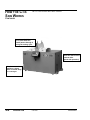
Traveling Saw
CTS Models 5, 7 and 9
Installation
Operation
Maintenance
Troubleshooting
Instant Access
Parts and Service
(800) 458-1960
(814) 437-6861
www.conairnet.com
The Conair Group, Inc.
One Conair Drive
Pittsburgh, PA 15202
Phone: (412) 312-6000
Fax: (412)-312-6227
UGE058/0803
Record your equipment’s
model and serial number(s) and the date you
received it in the spaces
provided.
It is important to record the model and serial number(s) of
your equipment and the date you received it in the User
Guide. Our service department uses this information, along
with the manual number, to provide help for the specific
equipment you installed.
Keep this User Guide and all manuals, engineering prints and
parts lists together for documentation of your equipment.
Date:
Document Number:
UGE058/0803
Serial number(s):
Model number(s):
Power Specifications:
Amps
Volts
Phase
Cycle
DISCLAIMER: The Conair Group, Inc., shall not be liable for errors
contained in this User Guide or for incidental, consequential damages in connection with the furnishing, performance or use of this
information. Conair makes no warranty of any kind with regard to
this information, including, but not limited to the implied warranties
of merchantability and fitness for a particular purpose.
Copyright 2003
THE CONAIR GROUP, INC.
All rights reserved
INTRODUCTION . . . . . . . . . . . . . . . . . . .1-1
Purpose of the User Guide . . . . . . . . . . . . . . . . . . . . . . . . .1-2
How the Guide is Organized . . . . . . . . . . . . . . . . . . . . . . .1-2
Your Responsibilities as a User . . . . . . . . . . . . . . . . . . . . .1-2
ATTENTION: Read this so no one gets hurt . . . . . . . . . . .1-3
How to Use the Lockout Device . . . . . . . . . . . . . . . . . . . .1-5
TABLE OF
CONTENTS
DESCRIPTION . . . . . . . . . . . . . . . . . . . .2-1
What is the CTS Saw? . . . . . . . . . . . . . . . . . . . . . . . . . . . .2-2
Typical Applications . . . . . . . . . . . . . . . . . . . . . . . . . . . . .2-2
How the CTS Saw Works . . . . . . . . . . . . . . . . . . . . . . . . . .2-3
CTS Saw Features . . . . . . . . . . . . . . . . . . . . . . . . . . . . . . .2-5
Specifications . . . . . . . . . . . . . . . . . . . . . . . . . . . . . . . . . .2-6
Optional Equipment . . . . . . . . . . . . . . . . . . . . . . . . . . . . . .2-7
INSTALLATION . . . . . . . . . . . . . . . . . . . .3-1
Unpacking the Boxes . . . . . . . . . . . . . . . . . . . . . . . . . . . . .3-2
Preparing for Installation . . . . . . . . . . . . . . . . . . . . . . . . . .3-3
Positioning the CTS Saw . . . . . . . . . . . . . . . . . . . . . . . . . .3-4
Connecting the Main Power Source . . . . . . . . . . . . . . . . . .3-6
Installing the Encoder . . . . . . . . . . . . . . . . . . . . . . . . . . . .3-7
Installing the Saw Blades . . . . . . . . . . . . . . . . . . . . . . . . . .3-8
Preparing for Testing . . . . . . . . . . . . . . . . . . . . . . . . . . . . .3-9
Testing the Installation . . . . . . . . . . . . . . . . . . . . . . . . . . . .3-9
OPERATION . . . . . . . . . . . . . . . . . . . . . .4-1
The Saw Control . . . . . . . . . . . . . . . . . . . . . . . . . . . . . . . .4-2
Machine Frame and Support System . . . . . . . . . . . . . . . . .4-4
Blade Height Adjustment . . . . . . . . . . . . . . . . . . . . . . . . . .4-4
Upper Clamp Adjustment . . . . . . . . . . . . . . . . . . . . . . . . . .4-4
Power Supply . . . . . . . . . . . . . . . . . . . . . . . . . . . . . . . . . .4-5
Control Panels . . . . . . . . . . . . . . . . . . . . . . . . . . . . . . . . . .4-5
Pneumatic Cylinder Operation . . . . . . . . . . . . . . . . . . . . .4-6
Electrical Operation . . . . . . . . . . . . . . . . . . . . . . . . . . . . .4-7
Machine Lubrication . . . . . . . . . . . . . . . . . . . . . . . . . . . . .4-8
System Inspection . . . . . . . . . . . . . . . . . . . . . . . . . . . . . . .4-8
Blade Replacement . . . . . . . . . . . . . . . . . . . . . . . . . . . . . .4-9
Chip Collection Shrouds and Blower Connection . . . . . . .4-10
MAINTENANCE . . . . . . . . . . . . . . . . . . . .5-1
Maintenance Features . . . . . . . . . . . . . . . . . . . . . . . . . . . .5-2
Warnings and Cautions . . . . . . . . . . . . . . . . . . . . . . . . . . .5-2
Maintenance Overview . . . . . . . . . . . . . . . . . . . . . . . . . . .5-4
Preventative Maintenance Schedule . . . . . . . . . . . . . . . . . .5-4
UGE058/0803
CTS Saw
i
MAINTENANCE
CONTINUED
. . . . . . . . . . .5-1
Checking the Blades . . . . . . . . . . . . . . . . . . . . . . . . . . . . .5-6
Checking Electrical Connections . . . . . . . . . . . . . . . . . . . .5-7
TROUBLESHOOTING . . . . . . . . . . . . . . . .6-1
Before Beginning . . . . . . . . . . . . . . . . . . . . . . . . . . . . . . . .6-2
A Few Words of Caution . . . . . . . . . . . . . . . . . . . . . . . . . .6-2
Identify the Cause of a Problem . . . . . . . . . . . . . . . . . . . . .6-3
Electrical Problems . . . . . . . . . . . . . . . . . . . . . . . . . . . . . .6-4
Product Quality Problems . . . . . . . . . . . . . . . . . . . . . . . . .6-5
Checking the Servo Amplifier . . . . . . . . . . . . . . . . . . . . . .6-7
Checking the Encoder . . . . . . . . . . . . . . . . . . . . . . . . . . . .6-8
APPENDIX . . . . . . . . . . . . . . . . . . . . . . . . .
Customer Service Information . . . . . . . . . . . . . . . . . . . . . .A-1
Warranty Information . . . . . . . . . . . . . . . . . . . . . . . . . . . .A-2
Servo Instructions . . . . . . . . . . . . . . . . . . . . . . . . . . . . . . .B-1
PARTS/DIAGRAMS
This section has been provided for you to
store spare parts lists and diagrams.
ii
CTS Saw
UGE058/0803
INTRODUCTION
● Purpose of the User Guide . . . .1-2
● How the User Guide
is organized . . . . . . . . . . . . . . .1-2
● Your Responsibilities
as a User . . . . . . . . . . . . . . . .1-2
● ATTENTION: Read this so
no one gets hurt . . . . . . . . . . .1-3
● How to Use the
Lockout Device . . . . . . . . . . . .1-5
UGE058/0803
CTS Saw
1-1
PURPOSE OF
THE USER
GUIDE
This User Guide describes the Conair CTS Saw and explains
step-by-step how to install, operate, maintain and repair this
equipment.
HOW THE USER
GUIDE IS
ORGANIZED
Symbols have been used to help organize the User Guide and
call your attention to important information regarding safe
installation and operation.
YOUR
RESPONSIBILITY
AS A USER
Before installing this product, please take a few moments to
read the User Guide and review the diagrams and safety information in the instruction packet. You also should review manuals covering associated equipment in your system. This
review won’t take long, and it could save you valuable installation and operating time later.
Symbols within triangles warn of conditions that could
be hazardous to users or could damage equipment.
Read and take precautions before proceeding.
1
Numbers within shaded squares indicate tasks or steps
to be performed by the user.
◆
A diamond indicates the equipment’s response to an
action performed by the user.
❒
●
An open box marks items in a checklist.
A shaded circle marks items in a list.
You must be familiar with all safety procedures concerning
installation, operation and maintenance of this equipment.
Responsible safety procedures include:
● Thorough review of this User Guide, paying particular
attention to hazard warnings, appendices and related diagrams.
● Thorough review of the equipment itself, with careful
attention to voltage sources, intended use and warning
labels.
● Thorough review of instruction manuals for associated
equipment.
● Step-by-step adherence to instructions outlined in this
User Guide.
1-2
INTRODUCTION
CTS Saw
UGE058/0803
We design equipment with the user’s safety in mind. You can
avoid the potential hazards identified on this machine by following the procedures outlined below and elsewhere in the
User Guide.
ATTENTION:
READ THIS
SO NO
ONE GETS HURT
DANGER: Sharp blades!
Most injuries caused by knife blades occur
when the saw has been turned off. Handle
blades with care at all times.
● Always wear cut-resistant gloves when the
blade guard is open and when handling
blades.
● Always lock out the saw before opening any
guards.
● Always wait until the saw blade has stopped
completely before opening the saw guard.
(approximately five minutes)
CTS Saw are equipped with several safety
devices to ensure safe operation. Never remove
or disable these devices to sustain production.
Operating without these devices can cause
severe injury.
● The STOP button activates a circuit that
stops the saw.
WARNING: Improper installation,
operation, or servicing may result in
equipment damage or personal
injury.
This equipment should only be installed,
adjusted, and serviced by qualified technical
personnel who are familiar with the construction, operation, and potential hazards of this
type of machine.
All wiring, disconnects, and fuses should be
installed by qualified electrical technicians in
accordance with electrical codes in your
region. Always maintain a safe ground. Do not
operate the equipment at power levels other
than what is specified on the machine serial
plate.
UGE058/0803
CTS Saw
INTRODUCTION
1-3
WARNING: Voltage Hazard
ATTENTION:
This equipment is powered by three-phase
alternating current, as specified on the machine
serial tag and data plate.
READ THIS
SO NO
ONE GETS HURT
A properly-sized conductive ground wire from
the incoming power supply must be connected
to the chassis ground terminal inside the electrical enclosure. Improper grounding can result in
severe personal injury and erratic machine
operation.
Always disconnect and lockout power before
opening the electrical enclosure or performing
non-routine procedures such as maintenance.
1-4
INTRODUCTION
CTS Saw
UGE058/0803
WARNING: Electrical hazard
Before performing maintenance or repairs on
this product, disconnect and lock out electrical
power sources to prevent injury from unexpected energization or start-up. A lockable device
has been provided to isolate this product from
potentially hazardous electricity.
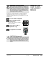
HOW TO USE
THE LOCKOUT
DEVICE
Lockout is the preferred method of isolating machines or
equipment from energy sources. Your Conair product is
equipped with the lockout device pictured below. To use the
lockout device:
1
2
Stop or turn off the equipment.
Isolate the equipment from
electrical power.
Turn the rotary disconnect switch to
OFF or O position.
3
Secure the device with an
assigned lock or tag.
4
The equipment is now locked
out.
O
CAUTION: Moving parts
Before removing lockout devices and returning
switches to the ON position, make sure that all
personnel are clear of the machine, tools have
been removed and all safety guards are reinstalled.
UGE058/0803
CTS Saw
INTRODUCTION
1-5
DESCRIPTION
● What is the CTS Saw? . . . . . . . .2-2
● Typical Applications . . . . . . . . . .2-2
● How the CTS Saw Works . . . . . .2-3
● CTS Saw Features . . . . . . . . . . .2-5
● Specifications . . . . . . . . . . . . . .2-6
● Optional Equipment . . . . . . . . . .2-7
UGE058/0803
CTS Saw
2-1
WHAT IS THE
CTS SAW?
The Conair CTS Saw is an on- or off-line sawing device capable of both on-demand and continuous cutting.
TYPICAL
APPLICATIONS
Conair CTS Saws can cut extrudable plastics and rubber both
on- and off-line. Other extrudable materials-foods, ceramics,
magnets, soaps, etc.-may also be cut depending on specific
application requirements.
CTS Saws are available with different cutting capacities (5, 7,
and 9 inches) to suit your specific needs. The standard saw
orientation is right-to-left, saws can also be made with a leftto-right orientation (see Specifications in this section). (The
illustrations in this User Guide represent the standard right-to
left configuration.)
CTS saws are limited to a specific range of product sizes
based on each unit's cutting capacity.
Different materials, line speeds, temperatures and material
cross-sections can result in different cutting torques. If you are
changing any of these parameters, consult your Conair service
personnel to be sure your equipment can handle the changes.
2-2
DESCRIPTION
CTS Saw
UGE058/0803
The Conair CTS saws are designed for the inline cutting of
profiles, pipe and tubing of a wide variety of sizes.
Located as part of the extrusion line downstream of the
extruder, the CTS performs five sequential functions in the cut
operation as follows:
HOW THE CTS
SAW WORKS
1. The saw table begins to travel with the product in a linear
motion then the clamps lock the product to the table.
2. The saw blade travels up and through the product
3. The saw blade returns to its down (home) position
4. The clamp releases the product
5. The saw table returns to its starting (home) position and
readies for the next cycle
These functions are preformed automatically with contact closure by means of either depressing the manual cut pushbutton
or by activating a flag switch mounted downstream of the unit
as standard.
There are available options that also initiate the cut cycle
including an internal timer, electronic length counter, or any
other device that has a N.O. (normally open) contact.
UGE058/0803
CTS Saw
DESCRIPTION
2-3
HOW THE CTS
SAW WORKS
The CTS Saw models have these features:
CONTINUED
Saw clamps hold the product in place while the
blades passes through it
during the cutting cycle.
Extruded material
enters the saw from the
upstream side.
(right-to-left operation)
Cut pieces are collected on a dump
table or carried away
on a conveyor
2-4
DESCRIPTION
CTS Saw
UGE058/0803
CTS SAW
FEATURES
Hinged table guards for
easy access to the clamps
Self-contained table to
reduce machine footprint
and enhance safety with no
moving parts extending past
the base
Front mounted
pneumatic flow
controls
Front mounted electrical controls
UGE058/0803
Access doors on
both ends of the saw
for easy maintenance.
CTS Saw
DESCRIPTION
2-5
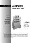
TPES014/0603
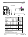
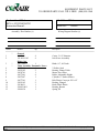
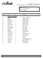
SPECIFICATIONS
TRAVELING CUT-OFF SAW
CTS Series
CTS-5, CTS-7 AND CTS-9
E
A
B
C
D
Side View
MODELS
Performance characteristics
Pipe capacity in. {mm} OD
Profile capacity in. {mm} HxW*
Blade size in. {mm}
Blade type
Blade drive motor Hp {kW}
Feed direction†
Dimensions in. {mm}
A - Height
B - Height to centerline
C - Width
D - Length
E - Table Travel
Weight lbs. {kg}‡
Installed
Shipping
Voltage Total Amps§
230V/3 phase/60 Hz
460V/3 phase/60 Hz
230V/3 phase/60 Hz (servo)
460V/3 phase/60 Hz (servo)
Compressed air requirement
Pressure psi {bars}
Consumption ft3/m {liter/sec}
NPT fitting size
Front View
CTS-5
CTS-7
CTS-9
5 {127}
4 x 8 {102 X 203}
18 {457}
carbide tipped
3 {2.2}
Right to left
7 {178}
5x13 {127 X 330}
23 {584}
carbide tipped
5 {3.7}
Right to left
9 {229}
6X17 {152 X 432}
27 {686}
carbide tipped
5 {3.7}
Right to left
57 {1448}
40 {1016}
46.5 {1181}
70 {1778}
24 {609}
60 {1524}
40 {1016}
57 {1448}
88 {2235}
24 {609}
63 {1600}
40.4 {1026}
61 {1549}
88 {2235}
24 {609}
575 {261}
675 {306}
825 {374}
925 {420}
1700 {771}
1800 {817}
9.7 A
4.9 A
26.2 A
13.1 A
15.1 A
7.6 A
30.6 A
15.3 A
15.1 A
7.6 A
30.6 A
15.3 A
80 {5.52}
5 {2.4}
3/8 in.
80 {5.52}
7 {3.3}
3/8 in.
80 {5.52}
8 {3.8}
3/8 in.
SPECIFICATION NOTES:
* The HxW dimension is provided for guidance only. The actual capacity can vary depending on the profile you are
trying to produce.
† Left to right feed direction is available as an option.
‡ If the optional chip collection system is ordered, add 50 lbs. {22.7 kg} to to the installed and shipping weights.
§ The optional chip collection system adds 6 A on 230V models; 3 A on 460V models.
UGE058/0803
CTS Saw
DESCRIPTION
2-6
Flag switch for cut length activation
Programmable length counter for cut length activation
OPTIONAL
EQUIPMENT
Servo control for optimal cut length and repeatable length accuracy
Dust collector system for material particulates
retention (highly recommended for proper operation)
Left to right machine operation
This options changes the machine direction from the standard
right to left extrusion flow.
Finer tooth blade for thin material and materials
that are easy to fracture.
UGE058/0803
CTS Saw
DESCRIPTION
2-7
INSTALLATION
● Unpacking the Boxes . . . . . . . . .3-2
● Preparing for Installation . . . . . .3-3
● Positioning the CTS Saw . . . . . .3-4
● Connecting the Main
Power Source . . . . . . . . . . . . .3-6
● Installing the Encoder . . . . . . . .3-7
● Installing the Saw
Blades . . . . . . . . . . . . . . . . . . .3-8
● Preparing for Testing . . . . . . . . .3-9
● Testing the Installation . . . . . . . .3-9
UGE058/0803
CTS Saw
3-1
UNPACKING THE
BOXES
The CTS Saw comes fully assembled in a single crate.
CAUTION: Lifting
To avoid personal injury or damage to the saw
lift the saw using a forklift or hoist with straps
that have been positioned at the saw's center of
gravity.
3-2
INSTALLATION
1
Carefully uncrate the saw and its components.
2
Remove all packing material, protective paper,
3
Carefully inspect all components to make sure
4
Record serial numbers and specifications in the
blanks provided on the back of the User Guide's title
page. This information will be helpful if you ever need
service or parts.
5
You are now ready to begin installation.
tape, and plastic. Compare contents to the shipping papers
to ensure that you have all the parts.
no damage occurred during shipping. Check all wire terminal connections, bolts, and any other electrical connections, which may have come loose during shipping.
Complete the preparation steps on page 3-3.
CTS Saw
UGE058/0803
1
❒
❒
❒
❒
❒
2
PREPARING FOR
INSTALLATION
You need these tools for installation:
wire strain relief
16- or 18-inch adjustable wrench
set of Allen wrenches
½ inch open or box end wrench
flashlight
Plan the location. Make sure the area where the saw
is installed has the following:
● A grounded power source. Check the saw’s serialal tag for the correct amps, voltage, phase and
cycles. All wiring should be completed by qualified
personnel and should comply with your region’s
electrical codes.
● Clearance for safe operation and maintenance.
Make sure there is enough clearance around the saw
for maintenance and servicing.
WARNING: Improper installation, operation, or servicing may result in
equipment damage or personal injury.
This equipment should only be installed, adjusted, and serviced by qualified technical personnel who are familiar with the construction, operation, and potential hazards of this type of
machine.
All wiring, disconnects, and fuses should be
installed by qualified electrical technicians in
accordance with electrical codes in your region.
Always maintain a safe ground. Do not operate
the equipment at power levels other than what
is specified on the machine serial tag and data
plate.
UGE058/0803
CTS Saw
INSTALLATION
3-3
POSITIONING
THE CTS SAW
1
Move the saw into position. Place the saw in position downstream of the belt puller.
CAUTION: Lifting
To avoid personal injury or damage to the saw,
lift the saw using a forklift or hoist with straps
that have been positioned at the saw's center of
gravity.
Saw
2
Determine the best distance from the belt puller to
the CTS Saw.
● For flexible products, the saw should be as close as
possible to the puller.
● For rigid products, leave enough space to allow
the product to flex during the cutting cycle. In some
cases, it may be necessary to allow 6-8 feet between
the puller and saw.
3
Align the saw with the extrusion line.
4
Measure the centerline height of the extrudate as
it exits the extrusion die. Adjust all equipment on the
extrusion line (sizing tank, cooling tanks, belt puller, and
saw) to this height.
continued on the next page
3-4
INSTALLATION
CTS Saw
UGE058/0803
5
6
Adjust the saw's floorlock/caster assembly to
the center height of the extrusion line using a 16- or 18inch adjustable wrench. Once the correct height is
reached, adjust the pad assembly to remove the weight
from the casters for operation. This minimizes machine
vibration during the cutting cycle.
POSITION THE
SAW
CONTINUED
Use a plumb line or laser to check for a
straight line from the extrusion die through each line
component to the saw center line of the table. Adjust as
necessary.
UGE058/0803
CTS Saw
INSTALLATION
3-5
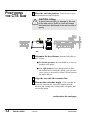
CONNECTING
THE MAIN
POWER SOURCE
WARNING: Electrical hazard
Before performing any work on this product, disconnect and lock out electrical power sources
to prevent injury from unexpected energization
or start-up. A lockable device has been provided to isolate this product from potentially hazardous electricity.
WARNING: Improper installation, operation, or servicing may result in
equipment damage or personal injury.
This equipment should only be installed, adjusted, and serviced by qualified technical personnel who are familiar with the construction, operation, and potential hazards of this type of
machine.
All wiring, disconnects, and fuses should be
installed by qualified electrical technicians in
accordance with electrical codes in your region.
Always maintain a safe ground. Do not operate
the equipment at power levels other than what
is specified on the machine serial tag and data
plate.
IMPORTANT: Always refer to
the wiring diagrams that
came with your saw before
making electrical connections. The diagrams show the
minimum size main power
cable required for your saw,
and the most accurate electrical component information.
1
Open the servo saw’s electrical
enclosure. Turn the disconnect dial on
the door to the OFF or O position and
open the door.
2
Insert the main power wire through the knockout
in the side of the enclosure. Secure the wire with a rubber
compression fitting or strain relief.
3
Connect the power wires to the terminals indicated
4
Check every terminal screw to make
5
Connect the ground
wire to either grounding
on the wiring diagram that came with your machine.
sure wires are secure. Gently tug each
wire. If a wire is loose, use a screwdriver
to tighten the terminal.
point shown in the diagram.
3-6
INSTALLATION
CTS Saw
UGE058/0803
CAUTION: Handle with care.
The encoder is a delicate piece of equipment
and must be handled gently.
INSTALLING THE
ENCODER
Conair uses bi-directional encoders to ensure that only product
that moves forward is counted.
Installing the encoder consists of several parts:
● the encoder
● the measuring wheel
● the connecting cable
Wheels
The encoder is fitted with a 1 foot circumference wheel which rides on
Encoder
either the upper belt of the belt puller or (for
rigid profiles and pipe) on the extrudate itself upstream of the
puller.
The encoder is supplied with an integral mounting bracket.
How and where you attach the encoder to the puller depends
on your particular puller and application.
Connecting
Cable
● If the wheel rides on the puller belt, make sure that its linear alignment is the same as the belt. Place the wheel near
the center of the belt to minimize bouncing. Try to avoid
cracks and other belt features that may affect accuracy.
● Make sure the location allows you to keep the wheel
clean. Any small buildup on the wheel will affect its circumference and change the cut length.
After the encoder is installed, attach it to the saw control using
the supplied cable. The cable has been hard-wired to the control at the factory.
UGE058/0803
CTS Saw
INSTALLATION
3-7
DANGER: Sharp blades!
INSTALLING THE
SAW BLADES
Most injuries caused by saw blades occur when
the saw has been turned off. Handle blades
with care at all times.
● Always wear cut-resistant gloves when the
blade guard is open and when handling
blades.
● Always lock out power to the saw before
opening any guards.
● Always wait until the saw blade has completely stopped before opening the saw
guard. (approximately five minutes)
CTS saws are equipped with several safety
devices to ensure safe operation. Never remove
or disable these devices to sustain production.
Operating without these devices can cause
severe injury.
1
Open the rear access door of the machine.
2
Remove the screws that retain the blade door
to the blade shroud and hinge open the door.
IMPORTANT: Always note the blade tooth direction
when removing blade to insure that the replacement
blade is installed the same. Rotating a carbide blade in
the wrong direction will usually damage the blade. As
standard, the blade rotation should have the top of the
blade rotating away from the front or operator side of the
unit.
3
Remove the hex nut.
The blade is held on with a hex nut tightened on the motor
arbor shaft. Based on either right to left or left to right saw
operation, the hex nut will be either a left hand or right
hand thread. A right to left saw operation means that the
product is entering the saw from the right side. A right to
left operating saw will use a left-handed threaded arbor.
This is done to insure that the arbor nut will want to continually tighten during blade rotation. The motor has an
arrow on the housing to indicate the arbor rotation.
Remove the hex nut using the spanner wrench provided to
hold the blade shaft. The saw blades will be removable at
this time.
3-8
INSTALLATION
CTS Saw
UGE058/0803
1
Make sure all components are installed according
to assembly drawings. Make sure that all bolts on the saw
have been tightened.
2
PREPARING
TESTING
FOR
Check that saw is firmly locked into position with
the anchoring screws.
3
Check that all wiring conforms to electrical
codes, and all wiring covers are in place.
4
Plug in the air supply
1
Turn on the main disconnect. Plug in the main
power cord and turn on the main disconnect.
2
Check that the E-Stop button is in the out,
extended position.
3
Press the vacuum start button.
4
Press the saw start button.
5
Check the saw blade rotation.
6
Make a sample cut. Restart the vacuum and the saw
TESTING THE
INSTALLATION
Check the rotation of the vacuum motor for correct phasing. (The phase in your plant may be different from the
Conair factory.)
Turn off the saw and vacuum.
The top of the saw blade should turn towards the front or
operator side. If the top of the blade is spinning away
from you or the operator side switch one of the 3-phase
plug wires. Then recheck the blade rotation.
motor and press the manual cut button. The saw should
make one sample cut.
If the saw is not working properly at any time, turn it off
immediately and refer to the Troubleshooting section of this
User Guide.
If you do not encounter any problems, proceed to the
Operation section.
UGE058/0803
CTS Saw
INSTALLATION
3-9
OPERATION
● The Saw Control . . . . . . . . . . . . .4-2
● Machine Frame and Support
System . . . . . . . . . . . . . . . . . . . .4-4
● Blade Height Adjustment . . . . . .4-4
● Upper Clamp Adjustment . . . . .4-5
● Power Supply . . . . . . . . . . . . . . .4-5
● Control Panels . . . . . . . . . . . . . .4-5
● Pneumatic Cylinder
Operation . . . . . . . . . . . . . . . .4-6
● Electrical Operation . . . . . . . . . .4-7
● Machine Lubrication . . . . . . . . .4-8
● System Inspection . . . . . . . . . .4-8
● Blade Replacement . . . . . . . . . .4-9
● Chip Collection Shrouds
and Blower Connection . . . .4-10
UGE058/0803
CTS Saw
4-1
THE SAW
CONTROL
IMPORTANT: Before applying power, ensure that the
SAW BLADE UP and TABLE FORWARD valves are
closed (fully clockwise), and that the saw blade is not
installed on the cut-off saw.
1
Connect the electrical line cord to a source of power compatible with the nameplate on the saw cut-off saw.
2
Connect the air supply to the FRL (filter-regulator-lubricator)
on the saw.
3
If the optional dust collector was purchased, install and connect the dust collector
4
Turn the main disconnect switch to the ON position; the
POWER ON light will illuminate.
5
Press Start or (if equipped with Dust Collector) turn Dust
Collector power “ON” first and then press saw motor “START”
6
Check the motor rotation. If the motor rotation is incorrect:
Reverse the connections at the AC plug end.
7
Once the rotation is correct, disconnect the power, and
install the blade on the cut-off saw.
8
Make sure that the FRL is set for 6--65 PSI
NOTE: Setting the FRL to higher level will only release
air from the system. The CTS is equipped with a relief
valve that is preset for approximately 70 PSI. The CTS
is equipped with a relief valve that is preset for approximately 70 PSI. The relief valve is in place to protect the
air components from damage due to excessive air pressure.
9
Press MANUAL CUT
10
Adjust the TABLE FORWARD speed control to match the
approximate line speed.
11
Adjust the SAW BLADE UP speed control to the desired
blade travel speed.
12
Set the blade height limit by adjusting the collar on the lifting
rod (located on the table surface)
continued on the next page
4-2
OPERATION
CTS Saw
UGE058/0803
13
Adjust the TABLE RETURN speed control to the
suitable travel return speed.
NOTE: The TABLE RETURN pressure must be set high
enough to return the table to the start position and trigger the TABLE START micro-switch.
14
THE CONTROL
FEATURES
CONTINUED
Adjust the clamp pressure regulator to grasp the profile firmly.
NOTE: Both the clamp pads and pressure can be
adjusted so that the profile is not crushed.
UGE058/0803
CTS Saw
OPERATION
4-3
MACHINE
FRAME AND
SUPPORT
SYSTEM
The machine frame is constructed of welded steel that has
been primed and painted to resist corrosion and provide a
maintenance free finish. The frame is supported by, four leveling screws, that both permanently fix the position of the unit
and also help accommodate any uneven flooring. These
screws have a welded hex nut to allow adjustment with a
wrench.
The motors and machine components are mounted inside the
frame and completely guarded for operator safety.
These and all guards should always remain securely in place
when machine is running and should be re-installed after any
maintenance procedures that have required their removal.
BLADE HEIGHT
ADJUSTMENT
The saw blades are mounted to and driven by a 3500 RPM
arbor motor. This motor is mounted on a pivot assembly,
which guides and secures the saw blade through the cutting
process.
There is adjustment for how high the saw blade will extend
through the table depending on the product being cut. For
maximum cut cycles, the saw blade should be adjusted so that
the blade just passes through the product before returning
home. Too much blade extension will waste valuable time and
limit the amount of cuts that will be available per minute. This
adjustment is made externally with the hand knob positioned
at the rear of the cutting table. Turning the knob counterclockwise will allow the blade to extend farther up through the
table and turning the knob clockwise will reduce the amount
that the blade will come up.
4-4
OPERATION
CTS Saw
UGE058/0803
As with the blade height adjustment, there is also a requirement to adjust the product clamps to adequately clamp different size products. The clamps are reversible and can be used
for clamping round or flat items. If you are running a round
product such as pipe or tubing, the side of the clamp that has a
"V" notch should be used and for flat surfaced products, the
straight side of the clamp should be used.
UPPER CLAMP
ADJUSTMENT
To remove and/or adjust each clamp assembly:
1
Lock out and tag out the power to the saw. See
Section 1: Introduction, How to use the Lockout Device.
2
Wait at least five minutes for the blade to stop
completely.
3
Pull the hitch pin from the clamp keeper pin
and remove both pins.
4
5
6
Slide the clamps to the desired position.
Re-insert the keeper pins.
Re-install the hitch pins.
IMPORTANT: The clamps should be set approximately
1/8"-1/4" above the product in the "up" position to allow
for positive clamping. Always check to see if setting is
correct before operating in line.
This equipment is powered by either 230 or 460 VAC , Three
Phase, as specified on the machine nameplate.
1
POWER SUPPLY
Connect the machine power through a fused disconnect of proper rating. Make sure the power is grounded
through the power cable to the plant electrical ground.
The operator control panels are located on the front of the saw
frame. The pneumatic control panel is located to the left of the
operator controls platform. It consists of a pressure regulator,
pressure gauge, and flow controls. All items are labeled, easily
accessible and lockable.
CONTROL
PANELS
The electrical control panel is located just to the right of the
pneumatic control. It consists of start and stop pushbuttons, a
power on light, a manual cut pushbutton and an emergency
stop extended pushbutton. All items are labeled and easily
accessible.
UGE058/0803
CTS Saw Manual
OPERATION
4-5
PNEUMATIC
CYLINDER
OPERATION
The carriage travel, blade pivot and clamp assemblies are
moved with air cylinders. The speed of the movement of the
carriage assembly is controlled by flow controls located on
the operator panel. Clockwise rotation will slow the table
speed and counterclockwise rotation will increase the table
speed.
The blade pivot assembly is moved up and down with an air
cylinder located below the table. It is controlled by flow controls mounted on the operator panel. These are labeled table
up speed and table down speed. Clockwise rotation will slow
the table movement speed and counterclockwise rotation will
increase the table movement speed.
The clamp assembly is moved up and down by air cylinders
mounted above the clamp. They are controlled by flow controls mounted on the Cylinders. Clockwise rotation will slow
the clamp movement speed and counterclockwise rotation will
increase the clamp movement speed.
The table and clamp pressure setting is adjusted with a pressure regulator located on the operator panel. The pressure
level setting is displayed on the gauge located above the regulator. The table and clamp pressure should never exceed 60
PSI.
The main filter/regulator/lubricator is mounted on the side of
the machine near the electrical enclosure and should be maintained as described in the manufacturers documentation.
This unit should always be supplied with clean dry air.
Incoming pressure should be set at approximately 65 PSI.
Maximum pressure is 70 PSI.
IMPORTANT: This unit should always be supplied with
clean dry air. Incoming pressure should be set at
approximately 65 PSI. Maximum pressure is 70 PSI.
4-6
OPERATION
CTS Saw Manual
UGE058/0803
The operation of the saw consists of an automatic sequence of
events.
1
To start the saw the main power must be on and the appropriate air supply to the machine. With the power on, the
control panel will have the power on light illuminated.
2
To start the saw motor, push the start button.
Once the saw motor is started, push the yellow manual cut
button and the machine will start its automatic cycle. The
clamps will come down and the table will begin to travel
away from its home position. Immediately after this happens, the saw pivot assembly will raise the blade up
through the table slot until it reaches its up limit switch.
Upon reaching this switch, the saw pivot will immediately
return down through the table, the clamps will raise and the
table will return to its home position, completing one
cycle.
ELECTRICAL
OPERATION
IMPORTANT: An important reminder is that the speed
settings of the pneumatic flow controls will affect the
cycle time of the machine. The flow controls must be set
properly to a compromise between cycle time and cut
quality. Flow control settings should be adjusted at this
time and fine-tuned during the initial phase of the saw
operation.
UGE058/0803
CTS Saw
OPERATION
4-7
MACHINE
LUBRICATION
The machine is supplied to you completely lubricated. After
running the unit for long periods of time, this lubrication will
break down and become useless.
Follow this lubrication chart for optimum performance.
Component
SYSTEM
INSPECTION
Type of Lubricant
Duration
Table Pivot Bearings Chassis Lube
6-9 months
Clamp Post Slides
5-6 months
Chassis Lube
Although this unit was designed to require a minimum amount
of maintenance, it should be inspected periodically to insure
that it remains in top operating condition.
Items to inspect are as follows:
- Saw Tracks- The steel tracks that the saw motor carriages
travel on, will after time, begin to wear from the constant contact with the cam rollers. They should be visually inspected
for wear and replaced as necessary.
- Saw Track Rollers- The steel cam rollers that the saw motor
carriages travel on, will after time, begin to wear from the
constant contact with the saw tracks. They should be visually
inspected for wear and replaced as necessary.
- Pneumatic System- Approximately once every 12 months or
sooner if able, all system pneumatic components should be
visually inspected. All hoses should be checked for wear or
damage. All regulators and flow controls should be adjusted
through their usable ranges to insure proper operation.
4-8
OPERATION
CTS Saw
UGE058/0803
1
Lock out and tag out the power to the saw. See
Section 1: Introduction, How to use the Lockout Device.
2
Wait at least five minutes for the blade to stop
completely.
IMPORTANT: Always note the blade tooth direction
when removing blade to insure that the replacement
blade is installed the same. Rotating a carbide blade in
the wrong direction will usually damage the blade. As
standard, the blade rotation should have the top of the
blade rotating away from the front or operator side of the
unit.
3
4
Open the rear access door of the machine.
5
Remove the hex nut.
Remove the screws that retain the blade door
to the blade shroud and hinge open the door.
The blade is held on with a hex nut tightened on the motor
arbor shaft. Based on either right to left or left to right saw
operation, the hex nut will be either a left hand or right
hand thread. A right to left saw operation means that the
product is entering the saw from the right side. A right to
left operating saw will use a left-handed threaded arbor.
This is done to insure that the arbor nut will want to continually tighten during blade rotation. The motor has an
arrow on the housing to indicate the arbor rotation.
Remove the hex nut using the spanner wrench provided to
hold the blade shaft. The saw blades will be removable at
this time.
UGE058/0803
CTS Saw
BLADE
REPLACEMENT
WARNING:
Electrical hazard
Before performing maintenance or repairs on
this product, disconnect
and lock out electrical
power sources to prevent injury from unexpected energization or
start-up. A lockable
device has been provided to isolate this product from potentially hazardous electricity.
CAUTION:
Moving parts
Before removing lockout
devices and returning
switches to the ON position, make sure that all
personnel are clear of
the machine, tools have
been removed and all
safety guards are reinstalled.
OPERATION
4-9
CHIP
COLLECTION
SHROUDS AND
BLOWER
CONNECTION
The CTS Saw has been equipped with a chip collection
shroud that is connected to the outside of the base to aid in
removing chips and debris from the blade area.
The success rate of chip removal is dependent on the type and
ability of the customer supplied removal system or Conair’s
optional vacuum system.
WARNING: If you did not purchase a Conair dust collection system you must connect a customer supplied dust
collector. Failure to do so may result in a fire hazard!
4-10
OPERATION
CTS Saw
UGE058/0803
MAINTENANCE
● Maintenance Features . . . . . . . .5-2
● Warnings and Cautions . . . . . . .5-2
● Maintenance Overview . . . . . . .5-4
● Preventative Maintenance
Schedule . . . . . . . . . . . . . . . . .5-4
● Checking the Blades . . . . . . . . .5-6
● Checking Electrical
Connections . . . . . . . . . . . . . .5-7
UGE058/0803
CTS Saw
5-1
MAINTENANCE
FEATURES
The CTS Saw models need regular, scheduled maintenance
for peak performance. Among the features that require maintenance are:
● Saw blades
● Blade mounting hardware
● Product guides
● The saw guard hardware
● Saw alignment
● Floor locks
● Shafts of optional slide rail system
● Electrical cables
● Control panel lights
WARNINGS
CAUTIONS
AND
To maintain the best performance of the saw it must be
cleaned and inspected regularly. Maintenance includes a daily,
weekly, quarterly, and semi-annual (every 6 months) schedule.
Use this maintenance schedule as a guide. You may need to
shorten the time of the maintenance schedule, depending on
how often you use the saw, and the types of material flowing
through it.
Follow all precautions and warnings when working on the
equipment.
WARNING: Improper installation,
operation, or servicing may result in
equipment damage or personal injury.
This equipment should only be installed, adjusted, and serviced by qualified technical personnel who are familiar with the construction, operation, and potential hazards of this type of
machine.
All wiring, disconnects, and fuses should be
installed by qualified electrical technicians in
accordance with electrical codes in your region.
5-2
MAINTENANCE
CTS Saw
UGE058/0803
WARNING: Voltage Hazard
This equipment is powered by alternating current, as specified on the machine serial tag and
data plate. Do not operate the equipment at
power levels other than what is specified on the
machine serial tag and data plate.
WARNINGS
CAUTIONS
AND
CONTINUED
A properly-sized conductive ground wire from
the incoming power supply must be connected
to the chassis ground terminal inside the electrical enclosure. Improper grounding can result in
severe personal injury and erratic machine
operation.
Before performing maintenance or repairs on
this product, disconnect and lock out electrical
power sources to prevent injury from unexpected energization or start-up. A lockable device
has been provided to isolate this product from
potentially hazardous electricity.
DANGER: Sharp blades!
Most injuries caused by saw blades occur when
the saw has been turned off. Handle blades
with care at all times.
● Always wear cut-resistant gloves when the
blade guard is open and when handling
blades.
● Always lock out power to the saw before
opening any guards.
● Always wait until the saw blade has completely stopped before opening the saw
guards. (approximately five minutes.)
CTS saws are equipped with several safety
devices to ensure safe operation. Never remove
or disable these devices to sustain production.
Operating without these devices can cause
severe injury.
UGE058/0803
CTS Saw
MAINTENANCE
5-3
MAINTENANCE
OVERVIEW
This section describes the daily, weekly, monthly and semiannual maintenance schedules that should be performed when
changing materials or lines, or when changing equipment, as
well as the maintenance procedures to follow.
Cutting either flexible or rigid materials generates tremendous
shock and vibration to the entire unit. Anything that can
loosen, will over time.
To maintain the best performance, follow this maintenance
schedule and develop an effective preventative maintenance
program.
PREVENTATIVE
MAINTENANCE
SCHEDULE
● Daily
❒ Checking saw blade(s)
Clean, sharpen or replace as needed (see Section 4,
Blade Replacement.)
❒ Inspecting the blade mounting hardware
The blade securing bolt should use both a lock washer
and flat washer, and be tightened enough to fully compress the lock washer. Replace the holding pins if they
appear worn.
❒ Inspecting the the saw product guides for wear and
alignment.
❒ Inspecting saw alignment
Proper saw alignment is critical for optimum performance. Use a plumb line or laser to check for a
straight line from the extrusion die to the saw bushings.
❒ Check floor locks
It is always recommended that the weight be removed
from the casters for optimum stability during cutting
cycles. Check to see if the floor locking mechanism is
properly adjusted.
5-4
MAINTENANCE
CTS Saw
UGE058/0803
● Weekly
❒ Blow or vacuum, dust and chips from all surfaces of
the saw. Open pneumatic and electrical enclosures
and remove the dust and chips from all components.
❒ Check that the FRL (filter-regulator-lubricator) for
the air input is filled with oil and that the oilier is
working. Pressure should be set for around 60 PSI.
This unit also has an automatic drain for any moisture that may develop. The bowl should be kept
clean to ensure it will operate properly.
● Quarterly
❒ Blow or vacuum, dust and chips from the inside
the saw. Remove all dust and chips from inside all
control cabinets. Remove any excess oil from the
pneumatic enclosure.
❒ Verify that all electrical terminals are tight.
❒ Check that all air lines are in order (free of cuts or
abrasions). Check the saw travel rails and rollers
for debris and wear.
❒ Check that the adjustable mufflers on the SAW
BLADE UP cylinder is set for a smooth downward
return.
❒ Check that the adjustable mufflers on the clamp
cylinder are set so that the clamp operates quickly a slow cycle on the clamp-down will cause inaccurate cuts in length.
❒ Check the condition of the clamp pads. If worn or
damages, replace with a new set of pads.
PREVENTATIVE
MAINTENANCE
SCHEDULE
CONTINUED
WARNING:
Electrical hazard
Before performing maintenance or repairs on
this product, disconnect
and lock out electrical
power sources to prevent injury from unexpected energization or
start-up. A lockable
device has been provided to isolate this product
from potentially hazardous electricity.
CAUTION: Moving
parts
Before removing lockout devices and
returning switches to
the ON position, make
sure that all personnel
are clear of the
machine, tools have
been removed and all
safety guards are reinstalled.
❒ Check the condition of the clamp pads. If worn or
damages, replace with a new set of pads.
❒ Check the condition of the blade. If the blade is
dull, have the unit sharpened; if it is damaged, have
the blade replaced.
UGE058/0803
CTS Saw
MAINTENANCE
5-5
CHECKING
BLADES
Blades become dull over time depending on the material being
cut, cut rate, blade speed, and blade material and thickness.
Check blades regularly for sharpness as well as scratches,
nicks, burrs, and material buildup. Clean, sharpen or replace
as needed (see Installing Saw Blades).
DANGER: Sharp blades!
Most injuries caused by knife blades occur
when the saw has been turned off. Handle
blades with care at all times.
● Always wear cut-resistant gloves when the
blade guard is open and when handling
blades.
● Always lock out the saw before opening any
guards.
● Always wait until the saw blade has stopped
completely before opening the saw guard.
(approximately five minutes)
CTS Saw are equipped with several safety
devices to ensure safe operation. Never remove
or disable these devices to sustain production.
Operating without these devices can cause
severe injury.
● The STOP button activates a circuit that
stops the saw.
WARNING: Improper installation,
operation, or servicing may result in
equipment damage or personal
injury.
This equipment should only be installed,
adjusted, and serviced by qualified technical
personnel who are familiar with the construction, operation, and potential hazards of this
type of machine.
All wiring, disconnects, and fuses should be
installed by qualified electrical technicians in
accordance with electrical codes in your
region. Always maintain a safe ground. Do not
operate the equipment at power levels other
than what is specified on the machine serial
plate.
5-6
MAINTENANCE
CTS Saw
UGE058/0803
WARNING: Electrical hazard
Before performing any work on this product,
disconnect and lock out electrical power
sources to prevent injury from unexpected energization or start-up. A lockable device has been
provided to isolate this product from potentially
hazardous electricity.
CHECKING
ELECTRICAL
CONNECTIONS
WARNING: Improper installation, operation, or servicing may result in
equipment damage or personal injury.
This equipment should only be installed, adjusted, and serviced by qualified technical personnel who are familiar with the construction, operation, and potential hazards of this type of
machine.
All wiring, disconnects, and fuses should be
installed by qualified electrical technicians in
accordance with electrical codes in your region.
Always maintain a safe ground. Do not operate
the equipment at power levels other than what
is specified on the machine serial tag and data
plate.
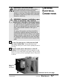
1
Be sure the main power is disconnected and
the saw is locked out. Always disconnect and
lock out the main power source before opening the unit or
servicing.
2
Turn the main power disconnect to the off
position before opening the electrical enclosure on the
back of the saw or the back of the control. This is a safety
device to prevent you from opening the doors if the power
is still on.
Main power
safety
disconnect
continued on the next page
UGE058/0803
CTS Saw
MAINTENANCE
5-7
CHECKING
ELECTRICAL
CONNECTIONS
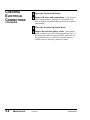
3
4
Open the electrical enclosure.
Inspect all wires and connections. Look for loose
wires, burned contacts, and signs of over-heated wires.
Have a qualified electrician make any necessary repairs or
replacements.
CONTINUED
5
6
Close the electrical enclosure door.
Inspect the exterior power cords. Cords should
not be crimped, exposed, or rubbing against the frame. If
the main power cord runs along the floor, make sure it is
not positioned where it could rest in pooling water or
could be run over and cut by wheels or casters.
5-8
MAINTENANCE
CTS Saw
UGE058/0803
TROUBLESHOOTING
● Before Beginning . . . . . . . . . . . .6-2
● A Few Words of Caution . . . . . .6-2
● Identifying the
Cause of a Problem . . . . . . . . .6-3
● Electrical Problems . . . . . . . . . .6-4
● Product Quality Problems . . . . .6-5
● Checking the Servo Amplifiers .6-7
● Checking the Encoder . . . . . . . .6-8
UGE058/0803
CTS Saw
6-1
BEFORE
BEGINNING
You can avoid most problems by following the recommended
installation, operation and maintenance procedures outlined in
this User Guide. If you have a problem, this section will help
you determine the cause and tell you how to fix it.
Find any wiring, parts, and assembly diagrams that were
shipped with your equipment. These are the best reference for
correcting a problem. The diagrams will note any custom features or options not covered in this User Guide.
Verify that you have all instructional materials related to the
saw. Additional details about troubleshooting and repairing
specific components are found in these materials.
Check that you have manual for other equipment connected in
the system. Troubleshooting may require investigating other
equipment attached to, or connected with the saw.
A FEW WORDS
OF CAUTION
WARNING: Improper installation, operation, or servicing may result in
equipment damage or personal injury.
This equipment should only be installed, adjusted, and serviced by qualified technical personnel who are familiar with the construction, operation, and potential hazards of this type of
machine.
All wiring, disconnects, and fuses should be
installed and adjusted by qualified electrical
technicians in accordance with electrical codes
in your region. Always maintain a safe ground.
Do not operate the equipment at power levels
other than what is specified on the machine
serial tag and data plate.
WARNING: Electrical hazard
Before performing maintenance or repairs on
this product, disconnect and lock out electrical
power sources to prevent injury from unexpected energization or start-up. A lockable device
has been provided to isolate this product from
potentially hazardous electricity.
6-2
TROUBLESHOOTING
CTS Saw
UGE058/0803
DANGER: Sharp blades!
Most injuries caused by saw blades occur when
the saw has been turned off. Handle blades
with care at all times.
● Always wear cut-resistant gloves when the
cutting chamber is open and when handling
blades.
● Always lock out power to the saw before
opening the cutting chamber.
● Always wait until the saw has completely
stopped before opening the cabinet door.
CTS saws are equipped with several safety
devices to ensure safe operation. Never remove
or disable these devices to sustain production.
Operating without these devices can cause
severe injury.
The Troubleshooting section covers problems directly related
to the operation and maintenance of the saw. This section does
not provide solutions to problems that originate with other
equipment. Additional troubleshooting help can be found in
manuals supplied with the other equipment.
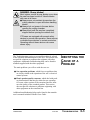
IDENTIFYING THE
CAUSE OF A
PROBLEM
The main problems you will see with the saw are:
● Saw operation problems, which focus on problems that
are clearly related to the operation of the saw’s electrical
control systems.
● Plastic product quality concerns, which deal with product characteristics that may be related to saw operation.
Of course, other sections of the extrusion line also influence the quality of the extruded product. This section
does not provide solutions to problems originating with
other equipment on the extrusion line.
Additional troubleshooting help can be found in the manufacturer’s manuals included with this User Guide.
UGE058/0803
CTS Saw
TROUBLESHOOTING
6-3
ELECTRICAL
PROBLEMS
Look in this section when you have problems such as lights on
the control that are working improperly, buttons that do not
execute the function properly, and when information input is
not executed properly.
Symptom
Possible cause
Solution
◆ Saw will not
The E-stop button is
depressed.
Make sure the E-stop is
extended.
Motor overload tripped
Reset motor overload.
start
Disconnect in the off posi- Turn disconnect to the on position.
tion.
◆ Saw blade runs
backwards
6-4
TROUBLESHOOTING
AC Power is phased
incorrectly for your plant
CTS Saw
Change the wire on the plug to
match your plants AC phasing.
UGE058/0803
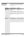
PRODUCT
QUALITY
PROBLEMS
Symptom
Possible cause Solution
◆ Cut not square
Product guides not
aligned square to the
blade face
Re-align the product guides.
Insure that the rear guide is
square with the saw blade and
tighten. Adjust the front guide
accordingly allowing enough
clearance for smooth product
passage.
◆ Crack or frac-
Blade speed too fast
Adjust speed control for blade
feed into part (slower)
Incorrect blade design
Investigate blade choice for the
application.
Incorrect cooling of
extrudate
Improve the molecular structure with variation of cooling
time or temperature.
Incorrect blade design
Investigate blade choice for the
application.
tures in cut surfaces
◆ General poor
cut quality
Blade running backwards Check motor rotation
Check blade installation
◆ Product melting
Blade speed too slow
Adjust speed control for blade
feed into part (faster)
Incorrect blade design
Investigate blade choice for the
application.
at cut
UGE058/0803
CTS Saw
TROUBLESHOOTING
6-5
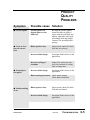
PRODUCT
QUALITY
PROBLEMS
CONTINUED
Symptom
Possible cause
Solution
◆ Incorrect cut
Encoder or input device
problem
Check encode or input device
Puller problem
Check puller for drive consistencies or any belt to product
slippage.
Counter problem
Check cut length counter
Saw clamps not holding
Check rubber saw clamps for
wear and replace as necessary
Roller ways dirty
Clean roller ways
Rodless cylinder problem
Check and clean rodless cylinder
Solenoid problem
Check table actuation solenoid
for proper operation
Low air pressure
Check main system regulator
for incoming air pressure settings
length
◆ Table motion
inconsistent
6-6
TROUBLESHOOTING
CTS Saw
UGE058/0803
The servo amplifier is equipped with a digital readout that
can be seen through the viewing window on the electrical
enclosure. This display shows amplifier status and error messages. Refer to the supplier's documentation included with
this User Guide.
CHECKING THE
SERVO
AMPLIFIER
NOTE: Make sure you look for servo amplifier messages
before you shut off the power.
UGE058/0803
CTS Saw
TROUBLESHOOTING
6-7
CHECKING THE
ENCODER
When the encoder is working properly, the encoder LEDs on
the control panel light or flicker as the encoder wheel moves
and generates signals. If the LEDs do not light when the
encoder wheel moves:
1
Check all connections.
2
Check the encoder cable for damage. If necessary, replace.
3
Check the connector that attaches the cable to
the encoder. Internal wiring may be shorted out if this
connector is not handled properly.
4
Check the encoder itself. There should be no play
in the shaft.
WARNING: Delicate equipment
The encoder is a delicate piece of equipment.
Any rough handling can damage fragile parts.
5
6-8
TROUBLESHOOTING
If all else fails, contact Conair Customer Service. See
Appendix page A-1.
CTS Saw
UGE058/0803
Conair has made the largest investment in customer support in
the plastics industry. Our service experts are available to help
with any problem you might have installing and operating
your equipment. Your Conair sales representative also can help
analyze the nature of your problem, assuring that it did not
result from misapplication or improper use.
To contact Customer Service personnel, call:
WE’RE HERE
TO HELP
HOW TO CONTACT
CUSTOMER
SERVICE
From outside the United States, call: 814-437-6861
You can commission Conair service personnel to provide onsite service by contacting the Customer Service Department.
Standard rates include an on-site hourly rate, with a one-day
minimum plus expenses.
If you do have a problem, please complete the
following checklist before calling Conair:
❒ Make sure you have all model, serial and parts list
numbers for your particular equipment. Service
personnel will need this information to assist you.
BEFORE YOU
CALL ...
❒ Make sure power is supplied to the equipment.
❒ Make sure that all connectors and wires within
and between the saw and related components have
been installed correctly.
❒ Check the troubleshooting guide of this manual
for a solution.
❒ Thoroughly examine the instruction manual(s)
for associated equipment, especially controls.
Each manual may have its own troubleshooting
guide to help you.
❒ Check that the equipment has been operated as
described in this manual.
❒ Check accompanying schematic drawings for
information on special considerations.
SERVICE INFORMATION
Additional manuals and
prints for your Conair
equipment may be
ordered through the
Customer Service or
Parts Departments for
a nominal fee.
APPENDIX A-1
EQUIPMENT
GUARANTEE
PERFORMANCE
WARRANTY
Conair guarantees the machinery and equipment on this
order, for a period as defined in the quotation from date of
shipment, against defects in material and workmanship under
the normal use and service for which it was recommended
(except for parts that are typically replaced after normal
usage, such as filters, liner plates, etc.). Conair’s guarantee is
limited to replacing, at our option, the part or parts determined by us to be defective after examination. The customer
assumes the cost of transportation of the part or parts to and
from the factory.
Conair warrants that this equipment will perform at or above
the ratings stated in specific quotations covering the equipment or as detailed in engineering specifications, provided
the equipment is applied, installed, operated and maintained
in the recommended manner as outlined in our quotation or
specifications.
Should performance not meet warranted levels, Conair at its
discretion will exercise one of the following options:
● Inspect the equipment and perform alterations or adjustments to satisfy performance claims. (Charges for such
inspections and corrections will be waived unless failure
to meet warranty is due to misapplication, improper
installation, poor maintenance practices or improper
operation.)
● Replace the original equipment with other Conair equipment that will meet original performance claims at no
extra cost to the customer.
● Refund the invoiced cost to the customer. Credit is subject to prior notice by the customer at which time a
Return Goods Authorization Number (RGA) will be
issued by Conair’s Service Department. Returned equipment must be well crated and in proper operating condition, including all parts. Returns must be prepaid.
Purchaser must notify Conair in writing of any claim and
provide a customer receipt and other evidence that a claim is
being made.
WARRANTY
LIMITATIONS
APPENDIX A-2
Except for the Equipment Guarantee and Performance
Warranty stated above, Conair disclaims all other warranties
with respect to the equipment, express or implied, arising by
operation of law, course of dealing, usage of trade or otherwise, including but not limited to the implied warranties of
merchantability and fitness for a particular purpose.
WARRANTY INFORMATION
UGE058/0803
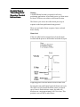
Conair Servo
Traveling Saw
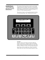
Operator Control
Instructions
The Operator Control provides an intuitive user-friendly
method to interface with the Conair Servo Traveling Saw.
Information is viewed and entered at the Operator Control
and is communicated to the servo positional amplifier via
the RS-232 serial communication link.
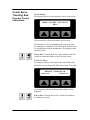
The Operator Control is a flat membrane panel consisting
of 22-keys and a large 2 line x 20 back lit LCD screen.
CONAIR SERVO SAW
Version 1.1
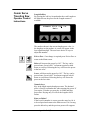
Soft Keys
Soft keys - these are the three keys directly under the
display. All three have a triangle on them. Occasionally,
pages will appear that allow the operator to use one of the
soft keys. On those occasions, text would typically appear
directly above the key and the key will have a function.
Think of the text as the soft key function indicator or title.
Appendix B-1 (1)
Conair Servo
Traveling Saw
Operator Control
Instructions
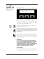
Numeric keys
These are the black keys containing numbers 0 to 9.
Numbers permit data entry of parameters. See Raise and
Lower for value trim.
Fixed Function Keys (at Bottom)
Underneath the numeric keys are fixed function keys. They
contain universal symbols and text. The fixed function keys
are Raise, Lower, Next, Prev (previous), Enter, Delete,
Exit, Menu and Mute. These functions are described in the
“Function keys - Fixed Functions” section of this manual.
LCD Screen
The screen shows various pages depending on operator
actions. In addition, it is used to indicate warnings.
Mostly, it is used for viewing status and for setting
parameters.
Appendix B-1 (2)
Conair Servo
Traveling Saw
Operator Control
Instructions
Contents
Page 4
...........Power up Sequence
Page 5
...........Main Screen – Length Counter
...........Count On/Off
Page 6
...........Total
...........Total Reset
...........Total On/Off
Page 7
...........Length Preset
...........Total Reset
Page 8
...........Homing
Page 9
...........Home Already
Page 10
...........Menu Area
...........Password Access
Page 11
...........Maintenance Area
...........Encoder Direction
Page 12
...........Preventive Maintenance Area
...........Power On Time
Page 13
...........Machine Cycles
...........Table Speeds
Page 14
...........Table Return Speed
Page 15
...........Table Advance Speed
Page 16
...........Factory Area
...........Error Message
Appendix B-1 (3)
Conair Servo
Traveling Saw
Operator Control
Instructions
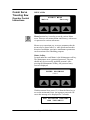
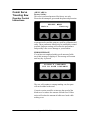
Power Up Sequence
At power up a series of system screens briefly appear. The
software is Red Lion’s Edict-97. This screen or similar
shows first.
Edict-97 Runtime
Ver. 5.05.117
Next, the Communications message appears
**STARTING COMMS**
If there are any problems with communications, this screen
will remain on longer than a couple of seconds.
If there are no communication problems the Conair Servo
Traveling Saw program will begin to run. The following
CONAIR SERVO SAW
Version 1.1
message or similar shows for 5-seconds.
After the 5 second delay the Main Screen will appear.
Appendix B-1 (4)
Conair Servo
Traveling Saw
Operator Control
Instructions
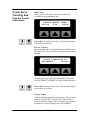
Main Screen
The Main Screen has three features. The top line displays
the Length Counter. The bottom line contains the two soft
key functions, Total and Length.
0000.000 in.
Total
Off
Length
Length Counter
The Length Counter displays counts only when the
machine is started and soft key On/Off is on. If the machine
is stopped or soft key On/Off is off, this counter will be
forced to zero.
The length counter resides in the servo drive. The main
screen shows snapshots of the count value that is read over
the communications channel. A slight delay in updates will
be noticed.
If a negative symbol is shown to the left of the count value,
the encoder signal is reversed, i.e. rotating in the wrong
direction. The Saw will not function while the encoder is
going negative. It is possible to correct this by using the
Direction function on the Maintenance Area page found in
the Menu area. This will be shown later in the Menu
section of this manual.
On/Off Softkey
Under the count in the center of the bottom line of the
display is a soft key labeled On or Off. Pressing this key
while On is displayed will disable the counter. Likewise
pressing this key while Off is displayed enables the
counter. Pressing the stop button forces the counter off.
Appendix B-1 (5)
Conair Servo
Traveling Saw
Operator Control
Instructions
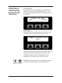
Total Softkey
By pressing the soft key located under the word Total on
the Main Screen, a six-decade total counter is available.
TOTAL 000,000 pcs.
Off
Exit
Reset
Total Screen
This is typically used to count cut pieces during the day or
days that the product is being produced.
Sample or aborted cuts are not counted. It is also possible
to turn this counter off or on.
Reset Softkey
Under the counter, on the right is a soft key labeled Reset.
Pressing this key will zero the counter.
Exit Softkey
Under the counter, in the center is a soft key labeled Exit.
Pressing this key will return the display to the Main screen.
On/Off Softkey
Under the counter on the left is a soft key labeled On or
Off. Pressing this key while On is displayed will disable the
counter. Likewise pressing this key while Off is displayed
enables the counter.
EXIT or PREV, fixed function keys return the display
to the Main screen.
Appendix B-1 (6)
Conair Servo
Traveling Saw
Operator Control
Instructions
Length Softkey
By pressing the soft key located under the word Length on
the Main Screen, the preset for the Length counter is
available.
LENGTH 0000.000 in.
Exit
The number shown is the current length preset value, i.e.
the length to cut the product. A cursor will appear in the
least significant digit. The user has a choice of ways to
adjust this number.
Exit or Prev- if no change is required press Exit or Prev to
return to the Main screen.
Raise will increase the preset by 0.01”. The key can be
pressed once for each 0.01” increment required or held
down to scroll up. Releasing the key will freeze the preset
at the last value.
Lower will decrease the preset by 0.01”. The key can be
pressed once for each 0.01” decrement required or held
down to scroll down. Releasing the key will freeze the
preset at the last value.
Numeric keys
Key in the length required and press enter. The decimal
place is fixed so remember this when entering the preset. If
you require 24 inches you must key in 24000 and then
press enter. Keying only 24 will set the length to 0.024
inches.
Enter or Delete?
If the keyed in number is correct press the enter key for it
to be accepted and return to the Main screen. If it is wrong
press the delete key and the previous preset will reappear.
Appendix B-1 (7)
Conair Servo
Traveling Saw
Operator Control
Instructions
Homing
A defined Home location is required for all servopositioning applications. After initial power up, Home must
be found. All moves are relative to the home location.
The Home cycle occurs once after initial power up in
response to the Start push button being pressed.
There are two kinds of home sequence, home seek and
home already.
Home Seek
If the saw table has been stopped away from the home
location and the power to the machine switched off, upon
reapplying power, the first motion will be a home seek.
Pressing the start push button begins the home seek cycle.
The table reverses towards the home sensor at reduced
speed. Once it finds the home sensor, the table will
decelerate to a stop approximately 0.0136 in. later. This
position is set to 0.000 at end of home.
Appendix B-1 (8)
Conair Servo
Traveling Saw
Operator Control
Instructions
Home Already
It is possible for the table to be in the home area already. In
this case, the table will move forward until it moves off the
home sensor. After this, motion is similar to the previous
description.
After a successful home has been completed, if the saw is
stopped and the power to the machine is left on, the table
position is still known. When the saw is restarted, the table
will return at the cut cycle, table return speed.
Appendix B-1 (9)
Conair Servo
Traveling Saw
Operator Control
Instructions
MENU AREA
SELECT MENU
Maint.
Factory
Menu function key is used to access the various Menu
areas. There are two menus Maint. and Factory, with access
via password to various sub-menus.
Menus are a convenient way to access parameters that do
not need to be altered often, i.e. table speeds and encoder
direction. In addition, preventive maintenance parameters
can be monitored for scheduling purposes.
Maint. Softkey
Located under the word Maint. is the Maintenance soft key.
The Maintenance area is password protected. This area
should only be accessed by qualified personal. After
pressing the Maintenance Softkey, the password entry
screen is displayed.
ENTER PASSWORD
****
With the numeral keys press 6 2 0 9 then the Enter key to
access the maintenance area. An improper password will
cause this message to be displayed for 3 seconds.
THE PASSWORD ENTERED
WAS INCORECT!
Appendix B-1 (10)
Conair Servo
Traveling Saw
Operator Control
Instructions
Maint. Area
There are three sub-menus, Dirctn, P/M, and Table
accessible in the maintenance area.
SELECT MAINT. AREA
Dirctn
P/M
Table
Exit or Prev- Pressing Exit or Prev will return the display
to the Menu Area screen.
Dirctn Softkey
By pressing the soft key located under the word Dirctn on
the Maint. Area Screen, the direction of the encoder can be
changed.
COUNT DIRECTION IS
INCORRECT
Change
Located on the lower left side of the display is the status
text (INCORRECT/CORRECT) for the encoder direction.
Exit or Prev- Pressing Exit or Prev will return the display
to the Maint. Area screen.
Change Softkey
With the machine stopped, by pressing the soft key located
under the word Change. The direction of the encoder is
reversed. After the change if the count direction is positive,
the status text will now display the word CORRECT.
Appendix B-1 (11)
Conair Servo
Traveling Saw
Operator Control
Instructions
P/M Softkey
Pressing the soft key located under the word P/M on the
Maint. area screen. Selects the P/M area screen. Two
preventive maintenance sub-menus, Time and Cycles can
be displayed.
SELECT P/M AREA
Time
Cycles
Time Softkey
Pressing the soft key located under the word Time on the
P/M area screen, selects the power-on time screen.
POWER ON 00000.0 Hrs
Exit
The Power-On time screen displays the total time in hours
that the machine has had the power switched on. This
information could be used for scheduling preventive
maintenance. The displayed time can not be reset.
Exit or Prev- Pressing Exit, Prev or the Softkey under the
word Exit returns the display to the P/M area screen.
Appendix B-1 (12)
Conair Servo
Traveling Saw
Operator Control
Instructions
Cycles Softkey
Pressing the soft key located under the word Cycles on the
MACH.CYCLES 00000000
Exit
P/M area screen, selects the machine cycles screen.
The Machine Cycles screen displays the total cycles that
the machine has completed. This information could be used
for scheduling preventive maintenance. The displayed total
can not be reset.
Exit or Prev- Pressing Exit, Prev or the Softkey under the
word Exit returns the display to the P/M area screen.
Table Softkey
Pressing the soft key located under the word Table on the
Maint area screen. Selects the Table area screen. Two table
SELECT DIRECTION
Return
Advance
travel direction sub-menus, Return and Advance can be
displayed.
Exit or Prev- Pressing Exit or Prev returns the display to
the Maint area screen.
Appendix B-1 (13)
Conair Servo
Traveling Saw
Operator Control
Instructions
Return Softkey
Pressing the soft key located under the word Return on the
ENTER TABLE RETURN
SPEED 1200.00 ipm.
Table area screen. Selects the Table Return Speed screen.
The number shown is the current return speed in inches per
minute. A cursor will appear in the least significant digit.
The user has a choice of ways to adjust this number. The
acceptable range is 120.00-1800.00 ipm
Exit or Prev- if no change is required press Exit or Prev to
return to the Table area screen.
Raise will increase the preset by 10.00 imp. The key can be
pressed once for each 10.00 ipm increment required or held
down to scroll up. Releasing the key will freeze the preset
at the last value.
Lower will decrease the preset by 10.00 ipm. The key can
be pressed once for each 10.00 ipm decrement required or
held down to scroll down. Releasing the key will freeze the
preset at the last value.
Numeric keys
Key in the speed required and press enter. The decimal
place is fixed so remember this when entering the preset. If
you require 1200 inches per minute you must key in
120000 and then press enter. Keying only 1200 will set the
speed to 12.00 inches per minute and the out of range
warning will appear on the screen for 5 seconds.
Enter or Delete?
If the keyed in number is correct press the enter key for it
to be accepted and return to the Main screen. If it is wrong
press the delete key and the previous preset will reappear.
Appendix B-1 (14)
Conair Servo
Traveling Saw
Operator Control
Instructions
Advance Softkey
Pressing the soft key located under the word Advance on
the Table area screen. Selects the Table Advance Speed
screen.
TABLE SYNC. RATIO
1.00:1
The number shown is the current table advance speed to
encoder speed ratio. A cursor will appear in the least
significant digit. The user has a choice of ways to adjust
this number. The acceptable range is 1.20-0.80 to 1 (+/20%)
Exit or Prev-if no change is required press Exit or Prev to
return to the Table area screen.
Raise will increase the preset by 0.01. The key can be
pressed once for each 0.01 increment required or held down
to scroll up. Releasing the key will freeze the preset at the
last value.
Lower will decrease the preset by 0.01. The key can be
pressed once for each 0.01decrement required or held down
to scroll down. Releasing the key will freeze the preset at
the last value.
Numeric keys
Key in the speed required and press enter. The decimal
place is fixed so remember this when entering the ratio. If
you require a 1.10:1 ratio you must key in 110 and then
press enter. Keying only 11 will set the ratio to 0.11and the
out of range warning will appear on the screen for 5
seconds.
Enter or Delete?
If the keyed in number is correct press the enter key for it
to be accepted and return to the Main screen. If it is wrong
press the delete key and the previous preset will reappear.
Appendix B-1 (15)
Conair Servo
Traveling Saw
Operator Control
Instructions
(MENU AREA)
Factory Softkey
This area is password protected for factory use only.
Please do not attempt to get around the password protection
SELECT MENU
Maint.
Factory
as parameters beyond this point are used for calibration and
setup. These parameters should only be modified by trained
personal. Improper settings will reduce the performance
and possibly cause severe damage to your machine.
ERROR MESSAGE
If a cut has not completed within a safe amount of table
travel this message is displayed. The message will remain
until any key is pressed.
COULDN’T COMPLETE
CUT IN SAFE DISTANCE
The saw will continue to attempt making cuts, but parts
will not be added to the total.
Corrective action would be to increase the speed of the
blade travel or reduce the amount of blade travel. Either
action will reduce the amount of table travel used while
making a cut.
Appendix B-1 (16)
EQUIPMENT PARTS LIST
TO ORDER PARTS CALL TOLL FREE (800) 458-1960
Product: Saw CTS-5
REV #: 023525L020/0703
Instruction Manual:
Model No.: CTS-5
Serial No.:
Assembly / Part Number (s)
Reference
Number
1
2
3
4
5
6
7
8
9
10
11
12
13
Part
Number
148840
Wiring Diagram Number (s)
Qty
Description
General
26682401
4
191-668-1105
4
Blades Opt.
2667760103
1
Table Assembly, Pneumatic / Servo
26678001
6
29031102
2
26676701
1
26677901
4
29037407
1
26677301
1
29031102
2
29120631
1
2990151001
1
29901930
1
* Indicates recommended spare parts |
error
>
Caster, 3-1/4” diameter
Jack Screw Assembly
Blade, 18”, 48 Tooth
V Roller, Steal
Bearing, Flange 2 Bolt
Motor, Saw Arbor
Roller, Adjustable Height
Cylinder, 6” Stroke (Motor)
Belt, Plastic Conveyor 28”x 64”
Bearing, Flanged
Knob, Black Plastic
Bearing, Bronze
Spring, SS
Indicates revisions change | Italicized indicates typographical
EQUIPMENT PARTS LIST
TO ORDER PARTS CALL TOLL FREE (800) 458-1960
Product:CTS-5
REV #: 023525L020/0703
Instruction Manual:
Reference
Number
Part
Number
14
15
16
17
18
19
20
21
22
23
24
25
26
27
28
29
30
31
32
33
34
35
36
37
38
39
Servo Opt. / Table Travel
20974117
1
29051011
1
29908007
4
2905320340850
1
29053632
1
2905320400850
1
29053631
1
2905320640850
1
29053633
1
2905338800850
1
29053322000850
1
26671748
2
26671810
2
26676901
1
26667660101
2
315-165-1012
4
315-167-3007
1
315-163-2017
1
315-167-2129
1
315-167-3013
5
266-766-02
1
315-170-1001
1
26635304
1
1545-30096
1
71301811
1
17302403
1
Qty
* Indicates recommended spare parts |
error
Description
>
2 of 3
Motor, Servo 3000rpm
Reducer, Gear 10:1
Bearing, Flanged
Sheave, Timing
Bushing, Sheave
Sheave, Timing
Bushing, Sheave
Sheave, Timing
Bushing, Sheave
Belt, Timing
Belt, Timing
Prox. Inductive
Prox. Cable
Switch, Magnetic
Solenoid Valve
Exhaust
Valve, Quick Exhaust
Gauge, 0-100psi
Flow, Control
Exhaust
Manifold
Filter, Regulator, Lubricator
Encoder, 3000PPR
Wheel, Encoder
Bracket, Arm
Arm Aluminum
Indicates revisions change | Italicized indicates typographical
EQUIPMENT PARTS LIST
TO ORDER PARTS CALL TOLL FREE (800) 458-1960
Product: CTS-5
REV #: 023525L020/0703
Instruction Manual:
Reference
Number
40
41
42
43
44
45
46
47
48
49
50
51
52
53
54
55
Part
Number
Qty
Description
3 of 3
Electrical Control, 3hp 230/460v (7140360201)
27500675
1
Switch Assy. Disconnect
27501514
1
Contact, Aux. 1N.O. 1N.C.
20973414
1
Breaker, Circuit
27500202
1
Contactor, Non Rev. 12 Amp
27500923
1
Contacts, Aux. 2N.O. 2N.C.
27500109
1
Transformer, 250VA 240/480v
20801476
1
Receptacle, Amphenol, 4 Pin
20801459
1
Connector, Amphenol, 10 Pin
26671601
2
Relay
26671602
2
Relay
1605-30000
1
Relay, Time
1608-30000
7
Semi-Cond. Varistor
26666702
1
Connector, Cable Gland
230 Volt
27501510
1
Starter, 6.3-10.0 Amp
20604012
2
Fuse, 1.5 Amp Type FNQ
1646-30192
1
Receptacle, Flanged
* Indicates recommended spare parts |
error
>
Indicates revisions change | Italicized indicates typographical