1
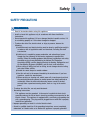
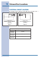
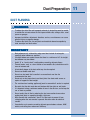
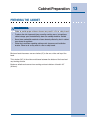
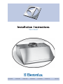
Installation Instructions
Vent Hood
E30WV60EPS
E36WV60EPS
E48WV12EPS
E308WV60ES
E368WV60ES
E488WV120S
5995438602
2 Finding Information
READ AND SAVE THESE INSTRUCTIONS
Attach your sales
receipt to this
page for future
reference.
NO
TE
NOTE
Installer: Leave instructions with owner.
Owner: Read your Hood Use & Care Manual. It contains important safety information for
operating this appliance. It also has many suggestions for getting the best results from
your hood.
Read all instructions before installing the hood.
For your safety, please read and observe all safety instructions. This guide will help
you anticipate all installation connections.
QUESTIONS?
For toll-free telephone support in the U.S. and Canada:
1-877- 4ELECTROLUX (1-877-435-3287)
For online support and Internet product information:
www.electroluxusa.com
©2005 Electrolux Home Products, Inc.
Post Office Box 212378, Augusta, Georgia 30917, USA
All rights reserved. Printed in the USA
Finding Information
TABLE OF CONTENTS
Finding Information ........................................... 2
Please Read And Save This Guide ................... 2
Questions .......................................................... 2
Table Of Contents .............................................. 3
Safety ................................................................... 4
Important Safety Instructions .............................. 4
Preparing for Installation .................................. 7
Verifying Package Contents ............................... 7
Installation Planning ........................................... 7
Specifications and Dimensions ........................... 8
Exhaust Duct Locations .................................... 9
Duct Locations ................................................... 9
Duct Preparation ................................................ 11
Cabinet Preparation ......................................... 13
Preparing the Cabinets .................................... 13
Electrical Power Supply ................................... 14
Requirements .................................................. 14
Installation ........................................................ 15
Installing the Hood ........................................... 15
Making the Electrical Connection ..................... 16
Operation ........................................................... 17
Verifying the Operation .................................... 17
3
4 Safety
IMPORTANT SAFETY INSTRUCTIONS
Safety Precautions
Do not attempt to install or operate your unit until you have read the safety
precautions in this manual. Safety items throughout this manual are labeled with a
Warning or Caution based on the risk type.
Definitions
This is the safety alert symbol. It is used to alert you to potential personal injury
hazards. Obey all safety messages that follow this symbol to avoid possible injury
or death.
!
!
WARNING
WARNING indicates a potentially hazardous situation which, if not avoided, could
result in death or serious injury.
!
CA
UTION
CAUTION
CAUTION indicates a potentially hazardous situation which, if not avoided, may result
in minor or moderate injury.
CA
UTION
CAUTION
CAUTION used without the safety alert symbol indicates a potentially hazardous
situation which, if not avoided, may result in property damage.
IMPOR
TANT
IMPORT
Indicates installation, operation or maintenance information which is important but
not hazard related.
Safety
SAFETY PRECAUTIONS
!
WARNING
• Read all instructions before using this appliance.
• Install or locate this appliance only in accordance with these installation
instructions.
• Do not operate this appliance if it has a damaged electrical conduit or wires, if it
is not working properly or if it has been damaged or dropped.
• To reduce the risk of fire, electric shock, or injury to persons, observe the
following:
a) Installation work and electrical wiring must be done by qualified person(s) in
accordance with all applicable codes and standards, including fire-rated
construction.
b) Sufficient air is needed for proper combustion and exhausting of gases
through the flue (chimney) of fuel burning equipment to prevent back
drafting. Follow the heating equipment manufacturer’s guidelines and safety
standards such as those published by the National Fire Protection
Association (NFPA), and the American Society for Heating, Refrigeration and
Air Conditioning Engineers (ASHRAE), and the local code authorities.
c) When cutting or drilling into wall or ceiling, do not damage electrical wiring
and other hidden utilities.
d) Ducted fans must always be vented outdoors.
e) Use this unit only in the manner intended by the manufacturer. If you have
questions, contact the manufacturer.
f) Before servicing or cleaning unit, switch power off at service panel and lock
the service disconnecting means to prevent power from being switched on
accidentally. When the service disconnecting means cannot be locked,
securely fasten a prominent warning device, such as a tag, to the service
panel.
• To reduce the risk of fire, use only metal ductwork.
• Grounding Instructions
This appliance must be grounded. In the event of an electrical short circuit,
grounding reduces the risk of electric shock by providing an escape wire for the
electric current. This appliance is equipped with a cord having a grounding wire
with a grounding plug. The plug must be plugged into an outlet this is properly
installed and grounded.
• Improper grounding can result in a risk of electric shock.
• Consult a qualified electrician if the grounding instructions are not completely
understood, or if doubt exists as to whether the appliance is properly grounded.
5
6 Safety
!
WARNING
• Do not use an extension cord. If the power supply cord is too short, have a
qualified electrician install an outlet near the appliance.
• This appliance should be serviced only by qualified service personnel. Contact the
nearest Electrolux authorized servicer at (877) 435-3287, or at
www.electroluxusa.com for examination, repair or adjustment.
• If the information in this manual is not followed exactly, a fire or explosion may
result causing property damage, personal injury, or death.
• Do not store or use gasoline or other flammable vapors and liquids in the vicinity
of this or any other appliance.
• Improper installation, adjustment, alteration, service, or maintenance can cause
personal injury or property damage. Refer to these instructions and the
accompany-ing Use & Care Manual. For assistance or additional information,
consult a qualified installer, service agency, or dealer.
• Keep appliance area clear and free from combustible material.
• For general ventilating use only. Do not use to exhaust hazardous or explosive
materials and vapors.
• To reduce the risk of a range top grease fire:
a) Never leave surface units unattended at high settings. Boilovers cause
smoking and greasy spillovers that may ignite. Heat oils slowly on low or
medium settings.
b) Always turn hood ON when cooking at high heat or when cooking flaming
foods.
c) Clean ventilating fans frequently. Grease should not be allowed to accumulate
on fan or filter.
d) Use proper pan size. Always use cookware appropriate for the size of the
surface element.
Preparing for Installation
VERIFY PACKAGE CONTENTS
•
Use and Care Manual
•
Suction Cup
INSTALLATION PLANNING
A qualified installer must complete the installation of this built-in appliance. Proper
installation is your responsibility.
Carefully check the location where the hood is to be installed. The hood should be
placed for convenient access. Make certain that electrical power can be provided in
the selected location.
Plan the installation so that all minimum clearances are met or exceeded.
Dimensions shown provide minimum clearances, unless otherwise noted.
The specified minimum cabinet depth and width must be provided.
Cabinet cutout dimensions must be used as indicated. All contact surfaces
between the appliance and the cabinet must be solid and level.
Make certain that you have everything necessary to ensure a proper
installation before proceeding.
7
8 Specifications and Dimensions
NO
TE
NOTE
All dimensional tolerances are + 1/16”, - 0” unless otherwise stated.
9” Hood Overall Dimensions
11 7/8"
(302mm)
"A"
9
(229mm)
Model
Width “A”
Width “B”
E30WV60EPS
29 7/8” (759mm)
23 13/16” (605mm)
E36WV60EPS
35 7/8” (911mm)
23 13/16” (605mm)
E48WV12EPS
47 7/8” (1216mm)
23 13/16” (605mm)
"B"
Overall Dimensions
Isometric View
(9” hood shown)
Figure 1
18” Hood Overall Dimensions
11 7/8"
(302mm)
Model
Width “A”
Width “B”
E308WV60ES
29 7/8” (759mm)
26 13/16” (681mm)
E368WV60ES
35 7/8” (911mm)
26 13/16” (681mm)
E488WV120S
47 7/8” (1216mm)
26 13/16” (681mm)
"A"
18
(457mm)
"B"
Overall Dimensions
Isometric View
(18” hood shown)
Figure 2
9
Exhaust Duct Locations
DUCT LOCATIONS
CL
Equal
CL
Equal
8" (203mm)
Round Duct
Collar
Equal
6 1/8"
(156mm)
CL
Equal
10" (254mm)
Round Duct
Collar
6 1/8"
(156mm)
CL
Vertical Exhaust Duct Location
E30WV60EPS, E36WV60EPS, E308WV60ES,
E368WV60ES
Top View
Vertical Exhaust Duct Location
E488WV120S
Top View
Figure 3
Figure 4
CL
Equal
Equal
CL
CL
CL
6"
6"
(152mm) (152mm)
Equal
6 1/8"
(156mm)
CL
Equal
3 1/4" x 10"
(83x254mm)
Duct
CL
4"
(102mm)
8" (203mm)
Round Duct
Collars
Vertical Exhaust Duct Location
E48WV12EPS
Top View
Horizontal Exhaust Duct Location
E308WV60ES, E368WV60ES
Rear View
Figure 5
Figure 6
CL
Equal
Equal
CL
CL
6"
6"
(152mm) (152mm)
CL
3 1/4" x 10"
(83x254mm)
Ducts
4"
(102mm)
Horizontal Exhaust Duct Location
E488WV120S
Rear View
Figure 7
12"
(305mm)
21"
5304449697 (533mm)
Custom Transition
for use with
E488WV120S
(not included)
8"
(203mm)
Figure 8
10 Exhaust Duct Locations
ELECTRICAL CONDUIT LOCATIONS
CL
"A"
1 1/2"
CL CL (38mm)
1 1/2"
(38mm) CL CL
CL
CL
CL
7/8"ø (11mm) Holes
"A"
1 1/2"
(38mm)
3/4"
(19mm)
7/8"ø (11mm) Holes
Conduit Location
E30WV60EPS, E36WV60EPS, E48WV12EPS,
E308WV60ES, E368WV60ES, E488WV120S
Top View
9” and 18” Hoods
Conduit Location
E308WV60ES, E368WV60ES, E488WV120S
Rear/Back View
18” Hoods
Figure 9
Figure 10
Electrical Conduit Locations
Model No.
Dimension “A” Conduit Location
E30WV60EPS
E308WV60ES
9” (752mm)
E36WV60EPS
E368WV60ES
8” (203mm)
E48WV12EPS
E488WV120S
14 7/16” (367mm)
Duct Preparation
DUCT PLANNING
!
WARNING
•
To reduce the risk of fire and to properly exhaust air, ducted fans must be vented
to outside. Do not vent exhaust air into spaces within walls, ceilings, attics, crawl
spaces or garages.
•
Improper installation, adjustment, alteration, service, or maintenance can cause
personal injury or property damage.
•
To reduce the risk of fire, use only duct work materials deemed acceptable by
state, municipal and local codes.
IMPOR
TANT
IMPORT
•
Best performance is achieved by using round duct instead of rectangular,
especially when elbows are required.
•
If multiple elbows are needed, ensure that there is a minimum of 24” of straight
duct between any two elbows.
•
Avoid “S” or “back to back” configurations caused by adjacent elbows.
•
Thermal breaks, such as a short section of non-metallic duct, should be used in
areas of extreme cold.
•
A back-draft damper at the duct outlet may also be required.
•
Do not use flexible metal duct.
•
Do not use duct work that is smaller in cross-sectional area than the
recommended size duct.
•
Do not rely on duct tape alone to seal duct joints. Use sheet metal screws as
require to support the duct weight.
•
The vent hood and cooking appliance(s) must be removable if service is required.
•
Be certain that the duct work does not interfere with floor joists or wall studs.
•
It is important to keep a minimum number of turns in the duct run, and to keep the
run as short as possible.
•
Do not restrict the air flow by reducing the duct cross-sectional areas when
making hard joints or squeezing through a tight area.
•
With concrete slab construction, “box-in” the duct work to prevent it from
collapsing when the wet concrete is poured. Also allow room for electrical
conduit.
•
Cross-drafts or air currents caused by adjacent open windows or doors, HVAC
outlets, and ceiling fans reduce vent efficiency.
11
12 Duct Preparation
IMPOR
TANT
IMPORT
•
Tape all duct joints securely to prevent combustion by-products, smoke or odors
from entering the home. This will also improve the efficiency of the system.
•
Do not exhaust more than one vent into a single duct run.
•
Only use ductwork constructed of materials deemed acceptable by state,
municipal and local codes.
Refer to the table below for recommended maximum straight lengths of duct to
provide adequate performance.
Model
E30WV60EPS
E36WV60EPS
E48WV12EPS
E308WV60ES
E368WV60ES
E488WV120S
Duct
Size
Maximum Equivalent Straight Lengths
10”
50’
3 1/4” x 10”
50’
8”
60’
E30WV60EPS
E36WV60EPS
E308WV60ES
E368WV60ES
Refer to the table below for recommended sheet metal elbows, transitions, and
wall cap equivalent straight lengths.
Recommended sheet metal elbows, transition, and wall cap equivalent straight lengths
3 1/4" x 10" 90° Elbow
3 1/4" x 10" 45° Elbow
3 1/4" x 10" Wall Cap
3 1/4" x 10"
90° Flat Elbow
15 Feet
7 Feet
2 Feet
20 Feet
Transistion
3 1/4" x 10" to Round
45° Elbow - Round Duct
90° T ransistion
3 1/4" x 10" to 8" Round
90° Elbow - Round Duct
25 Feet
8" Diameter - 7 Feet
10" Diameter - 5 Feet
8" Diameter - 4 Feet
10" Diameter - 4 Feet
8" Diameter - 3 Feet
10" Diameter - 2 Feet
Cabinet Preparation
PREPARING THE CABINET
!
WARNING
•
Failure to provide proper minimum clearance may result in a fire or safety hazard.
•
To reduce the risk of personal injury caused by reaching over a hot appliance,
cabinet storage space located directly above the cooktop should be avoided.
•
Do not store combustible materials or items adversely affected by heat in cabinet
areas above the appliance.
•
Follow the instructions regarding minimum safe clearances and installation
location. Failure to do so may result in a fire or safety hazard.
Minimum hood clearances are zero inches (0”) to the rear, sides and top of the
hood.
Thirty inches (30”) is the minimum distance between the bottom of the hood and
any cooking surface.
Maximum effective clearance from cooking surface to bottom of hood is 36”
(914mm).
13
14 Electrical Power Supply
REQUIREMENTS
!
WARNING
Failure to disconnect power may result in electrical shock or fire hazard! If the
electric service provided does not meet the product specifications, do not
proceed with the installation. Call the selling dealer or a licensed electrician.
It is the owner’s responsibility to ensure that the electrical connection of this
appliance is performed by a qualified electrician. The electrical installation including
minimum supply wire size and grounding, must be in accordance with the latest
revision of the National Electric code ANSI/NFPA and local codes and ordinances.
A copy of this standard may be obtained from:
National Fire Protection Association
1 Batterymarch Park
Quincy, Massachusetts 02269-9101
The correct 120VAC, 60Hz, 15A circuit must be supplied for this appliance from a
separate, grounded, circuit that is protected by a properly sized circuit breaker or
time delay fuse.
15
Installation
INSTALLING THE HOOD
First temporarily mount a 2x4 ledger board 30” (762mm) from the finished
countertop. Then, remove the filters from the hood canopy and remove the shields
below the power ventilator. Secure the hood through the keyhole slots in the top of
the hood and/or the slot hole in the rear of the hood. Remove the temporary
support ledger.
Top
mounting holes
(both sides)
Rear
mounting holes
Temporary
support ledger.
Temporary Support Ledger Installation
(9” Shown)
Figure 11
Top
mounting holes
(both sides)
Rear
mounting holes
Temporary
support ledger.
Temporary Support Ledger Installation
(18” Shown)
Figure 12
16 Installation
MAKING THE ELECTRICAL CONNECTION
!
WARNING
•
Ensure that the power supply is disconnected before proceeding.
•
Verify that the power supply matches the ratings found on the appliance data
plate before proceeding.
•
The complete appliance must be properly grounded at all times when electrical
power is applied.
•
Do not ground the appliance with the neutral (white) house supply wire. A
separate ground wire must be utilized.
•
If aluminum house supply wiring is used, splice the appliance copper wires to the
aluminum house wiring with special connectors designed and agency-certified
for this purpose. Follow the connector manufacturer’s recommended procedure
carefully. Improper connection can result in a fire hazard.
•
Failure to complete electrical connections properly may result in a damaged or
nonfunctional system. Follow the wiring diagrams carefully to ensure a proper
installation.
Figure 13
L1
BLK
N1
WHT
Gnd
d
GRN
120VAC, 60Hz, 15A
Supply power from
dedicated circuit breaker
Hood Wiring Diagram
Electrical power source wiring can be
connected through the top or back of the
hood. Access the wiring inside the hood
canopy in the area to the right side of the
power ventilator.
Connect the pre-wired 12” long black, white
and green wires to the corresponding
black, white and ground (green) wire from
the power source wiring. Use wire nut
connectors to secure the connections.
Operation
VERIFYING THE OPERATION
!
WARNING
•
If the hood is not operational after completion of the installation, do not attempt
to repair it. See the Problem Solving section of the Use & Care Guide, then call a
qualified service technician if the system is still not functional.
•
Always disconnect the appliances from the electrical power when servicing them.
•
Install the filters.
•
Verify that the hood control knobs are in the OFF position.
•
Turn on the main power supply.
•
The hood has two knobs that control the function of the hoods Halogen
lights and the exhaust blower. Turning the knobs clockwise will turn on
the lights and the blower. The blower has a variable speed range between
settings.
17
18
Adjun
de com
esta p
refere