1
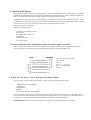
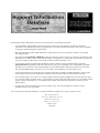
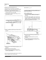
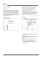
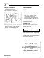
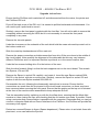
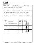
•
All the documents in this newsletter are available on the Support Information Database (SID).
•
Back-issues are available via SID and may also be obtained from Customer Services.
•
Any suggestions you may have for information you would like to see in future issues should be sent to
the Newsletter Editor via SID mail (ID 1000) or by post at our head office address.
Page
Document description
SID Ref.
1
News Bulletin
CSN0015
3
Support Information Database - Latest News
CSN0016
4
Application Notes Index - Archimedes
CSN0017
5
Application Notes Index - BBC Micro
CSN0018
6
Application Notes Index - Master128 &512
CSN0019
7
Application Notes Index - Z80, View & Econet
CSN0020
Appendix:
A3000 Expansion
1Mb RAM Upgrade
Serial Port Upgrade
Fitting an Econet Module
Filestore E01 Field Change Order
FCO2005
Filestore E01S Field Change Order
FCO2006
Archimedes 400/1 Series Field Change Order
FCO2007
ACORN, ARCHIMEDES, MASTER and ECONET are trademarks of Acorn Computers Limited.
Every effort has been made to ensure that the information in this newsletter is true and correct
at the time of printing. However, the products, upon which the information in this newsletter is
based, are subject to continuous development and improvement and Acorn Computers Limited
reserves the right to change their specifications at any time. Acorn Computers Limited cannot
accept liability for any loss or damage arising from the use of any information or particulars
contained within this newsletter.
Produced using Acorn Desktop Publisher
1. Bracket for Miniscribe Drive - Part Number: 0177,001
The item in last issue of the News-letter covering the new brackets that are required when replacing Tandon or
Western Digitial for Miniscribe drives only applies to the Archimedes 440's, or 305's and 310's that have had a
hard disc upgrade fitted. The new brackets are NOT required on the 400/1 series machines.
2. Taxan 770 Multi-sync Monitors
There has been reports of incompatability between some early Archimedes 400/1 Series, the new A3000 and
Taxan 770 Multi-sync Monitors. To be precise, the signal input impedance of the SYNC lines,(VS*, HS* and
CS*), is too low for our output drivers.
The 400/1 and A3000 series has an additional signal present on the video connector, namely "MODE". This is to
provide a "device present" signal to a domestic T.V. when used via a SCART interface.The Taxan requires this
extra signal, if present, to be in a defined logic state. This is then used within the monitor to select screen size. At
the moment, due to the loading of the monitor, the computer can not drive this signal to a guranteed logic state, thus
causing the Taxan to jitter.
To cure this problem.
A400/1 - fit a shunt to Link 2, located near the Analogue RGB socket.
A3000 - fit a shunt to Link 25
This may result in the need to adjust the monitor display size using the controls at the rear. All rear buttons
should be in the out position.
3. EPSON GQ3500 Printer in Laserjet emulation
Rescently we have had reports of problems using the Epson GQ3500 printer in Laserjet emulation mode with the !
PrinterLJ application under RISC OS being driven via the parallel port. When printing graphics, faint white lines
appear on the print out.
This is caused by an incorrectly set DIP switch on the External Printer Interface Card. DIP switch SW4-4, when
in the OFF position strips the eighth data bit which controls graphics output, thus causing the white lines. Setting
the DIP switch to the ON position will solve the problem.
Information covering DIP switch SW4-4 can be found on page 13 (problem solving section) of the GQ3500
Manual.
4. EPSON LQ-850 Printers
Early versions of the LQ-850 do not support the [Esc]+ sequence required for 360x360 dpi printing. This resulted in
printout that had double spaced lines of graphics terminated by backslashes. This is purely a software problem and
there is no mechanical reason for the printer not being able to support this resolution.
A ROM change to the printer will solve the problem. To establish which version of the ROM the printer has, a self
test should be run by turning the printer on with the Form Feed button held down. The ROM number will be printed
in the top left. If it is not one of the three following then an upgrade will be required.
M 80483, N 91785, N 92687 New
ROMs can be obtained from:
Apropriate Technolodgy Limited,
Aptec House,
South Bank Business Center
Ponteon Rd,
London, SW8 5AT
Tel: 01-627-1000
5. Connections between the Archimedes Serial Port and an Apple Laserwriter
Below are the details of the pin connections between the Archimedes serial port and an Apple Laserwriter and
how the setup options should be set within the !PrinterPS application supplied with RISC OS.
Laserwriter baud rate : 9600
Data Format
Bits : 8
P a r i t y : O f f Stop
Bits : 2 XON/XOFF :
selected
6. SONY 3.5" disc drives - Out of Warranty Servicing Facilities.
Out-of-warranty service facilities for the Sony 3.5" disc drives have been established with:
Bedford Technical Engineering,
P.O. Box 31,
Ampthill Road,
Bedford.
Tel: 0234 226474; Fax: 0234 226090.
They will provide a repair service for £20 plus parts (excl. VAT). Where the total repair cost is likely to exceed
£45, the customer will be advised prior to any repair proceeding. BTE are also in a position to offer additional postwarranty services, and contact should be made directly with BTE for further information.
IN-WARRANTY SONY 3.5" disc drive failures will continue to be replaced through Acorn Spares.
Following last month's SID bulletin, here are seven reasons why you should be using SID:
•
As from Monday, 4th September, the Prestel gateway will be open, thus allowing any Prestel or Micronet
subscriber to use SID from as little as 1p per minute on top of their normal time charge. This can be compared
to the 8p per minute charged for using Fastrak.
•
Micronet reckon that of their 20000 subscribers, 10000 of them own Acorn computers. That is a lot of people
who might use SID.
•
You can advertise FREE OF CHARGE on SID. Just prepare a mode 7 image of your advert and send it to the
SID Editor at the address below. Providing the advert is acceptable (ie it meets ASA rules and does not advertise
non-Acorn related products) then it will be put on SID for all the subscribers to see.
•
An increasing amount of technical documentation and test software is being released to dealers and ASCs
EXCLUSIVELY through SID. That means that the only way you can get hold of it is to download it from SID.
Examples are test software for the A3000 and the Universal PCB, and new RISC OS printer drivers. The latter
may be downloaded and put onto discs for your customers, thus enhancing your after-sales service.
•
As from November, the Customer Services newsletter will only be available via SID telesoftware. Only a single
sheet of paper will be sent out, detailing the contents of the newsletter and how to download it from SID.
•
Fast technical support. If you have ever rung the dealer hotline and got the engaged tone, why not send your query
to a technical mailbox on SID? There is a good chance it will be answered within an hour of you sending it if the
answer is known! Alternatively, you could share the problem with other STD subscribers by leaving it on a
bulletin board.
•
Its cheap! Just a local call and 6p plus VAT per minute of use. You will get billed once a quarter, with a
minimum charge of £10 per quarter.
So, if you haven't already got a SID ID, we would recommend you apply now! To do so, please write to:
The SID Editor
Acorn Computers Ltd
Fulbourn Road
Cherry Hinton
Cambridge
CB1 4JN
The following is a list of application notes available on SID for the
Archimedes range of personal workstations.
• Each document may be retrieved by typing *SID Ref# Eg: *0310011# will take you to the Archimedes 300
series hardware product spec frame from which you can download the document.
SID Ref:
Document Title
0310011
Archimedes 300 series hardware product specification
0310022
Sound commands on the Archimedes machine
0310032
Pinouts on the Archimedes machine
0310052
Archimedes Serial Port Application Note (Issue D)
0310063
6502 to ARM - Application Note
0310071
Archimedes Podule Loaders
0310091
Archimedes applications: authors' guidelines
0310101
A Series Podules
0340011
Archimedes 6052 Emulation: Application Note
0310111
RISC OS Application Image Format (previously Arthur Image Format)
0310121
Acorn Library Format / Object Library Format
0310131
ARM Object Format
The following is a list of applicatiom notes available on SID for the
BBC Micro.
• Each document may be retrieved by typing: *SID Ref # Eg: *0040151# will take you to the "Speech System User
Guide errata" frame from which you can download the document.
SID Ref:
Document Title
0040011
0040021
0040031
Test equipment for the BBC and Electron microcomputers
Fitting two single disc drives to a BBC computer
Differences between BASIC I and BASIC 1I
0040041
0040051
0040061
0040071
Cassette recorder usage with BBC and Electronc computers
Use of EPROMs in sideways ROM sockets of the BBC microcomputer
Parallel printer port: issue 2 board modification
Use of *FX3 - erratta to the User Guide
0040081
0040091
0040101
Changing the BREAK key
Buffer Indirections as used in the BBC microcomputer
BBC User Guide Errata: UK Version
0040111
Modification to cure teletext mode deterioration
0040122
0040131
0040141
0040151
0040163
Second processor timing incompatibility
Modifications to remove random keyboard interrupts
5.25" disc interface upgrade for the model B microcomputer
Speech System User Guide errata
Differences between DFS/NFS and DNFS
0040171
0040181
0040191
0050011
0130011
0130021
0130031
0130041
0150011
Hardware Description of the BBC Model B Microcomputer
Programming the BBC microcomputer serial processor IC
Disabling the interlace in mode 7
64K sideways RAM daughter board fitting instructions
Electron Production Inspection Tester (P.I.T.)
Electron Watchdog
Acornsoft games for the Electron
PCB Component changes for different ULA types for Electron
Electron Plus 3 User Guide amendments
The following is a list of application notes available on SID for the
Master 128 & Master 512.
• Each document may be retrieved by typing: *SID Ref # Eg: *0190011# will take you to the "Advanced Disc Filing
System Application Note" frame from which the document can be downloaded.
SID Ref:
Document Title
0190011
Advanced Disc Filing System application note
0190022
0190031
Advanced Network Filing system application note
Differences between BASIC 2 and BASIC 4
0190042
0190053
0190061
0190071
0190082
0190092
0190161
0190171
Master series cartridge interface application note
Master series Welcome Disc "Convert" utility: functional description
Expanding files under ADFS
The use of BAS 128 on the Master 128 and Master Compact
Summary of the features of EDIT
Summary of the functional differences between the Master 128 and
BBC models B and B+
Master 128 operating system description
Master 128 operating system commands part 1
Master 128 operating system commands part 2
Master series terminal software: functional description
Copying files from the cassette filing system to other filing systems
on the Master 128
Master 128 hardware description
Known differences for the Master RS423 serial interface
0190181
0220021
0200032
0200042
0200052
0200061
0200071
Changes between different versions of the Master series 1770 DFS
Media compatibility with the Master Compact
Master 512: applications compatibility and software list part 1
Master 512: applications compatibility and software list part 2
Master 512: applications compatibility and software list part 3
Master 512: technical information and monitor documentation part 1
Master 512: technical information and monitor documentation part 2
0190102
0190111
0190121
0190131
0190141
The following is a list of application notes available on theSID info server for the
Z80, the View family & Econet.
• Each document may be retrieved by typing: *SID Ref # Eg: *0300011# will take you to the "Z80 documentation errata" frame from which the document may be downloaded.
SID Ref:
Document Title
0300011
Z80 documentation errata
0300021
Using CP/M with non-standard disc configurations
0230011
0230021
0230031
0230041
0230051
0230061
0230071
0230081
0090011
0090021
0090031
View hints & tips
Printing labels from a View macro file
ViewStore hints & tips
Copying the ViewSpell utility disc to ADFS
Copying the ViewStore utility disc to ADFS
How to write a ViewStore utility, part 1
How to write a ViewStore utility, part 2
How to write a ViewStore utility, part 3
Econet System User Guide errata
Econet fault-finding guide part 1
Econet fault-finding guide part 2
3000
A3000 expansion
Internal expansion
Power supply
DANGER
DANGEROUS VOLTAGES ARE EXPOSED INS1DE
THE CASE OF THE COMPUTER WHEN THE
COVER IS REMOVED. THE COMPUTER SHOULD
BE DISCONNECTED FROM 'THE MAJNS SUPPLY
BEFORE THE COVER IS REMOVED.
The following internal upgrades are currently available
for the A3000 computer:
• User port / MIDI interna1 expansion card
• 1 Mb Ram upgrade
• Serial port
• Econet module
The maximum power available from the +5V rail is 600
mA. The maximum dissipation inside the case Js 0.5W
(100mA).
5-way connectors
There are two 5-way 0.1 inch connectors fitted to the
main circuit board:
Interface
The electrical signals available on the internal
expansion are a subset of those described in 'A Series
Podules', available from Acorn Customer Service on the
SID system (Doc Ref 0310101) or as an Application
Note.
The connection is via two 17-way 0.1 inch pitch
connectors. Expansion cards should use 0.025 in
square pin headers.
The interface is configured as 'Podule 1, Module 1'.
Expansion bus connectors
Pin no.
1
SK8
C[01
SK9
2
C[1]
3
Br
4
IORQ*
0v
REF8M
PFIQ*
Ms[1]*
5
IOGTt*
+5
Note: Pin 1 is at the righthand end, when viewed from
the front of the computer.
N.B. C[0] and C[1] are used as the 1IC bus.
It is recommended that the load on each signal does nct
exceed 3HCT gates or that stated in 'A Series
Podules'. Any upgrade must be able to drive at least 7
HCT and 3 TTL loads on the data bus.
Mechanical
The rear panel required is shown in the drawing at the
back of this manual. The size of the User Port / MIDI
expansion card PCB and position of the connectors is
also shown in the drawing included at the back of the
manual.
Pin no.
SK3
SK11*
1
+5v
0v
2
3
PWE*
PS1*
+5v
PRE*
4
CLK2
PRnW
5
6
LA[2]
LA[3]
LA[4]
LA[5]
7
8
9
BD[0]
BD[1]
BD[2]
LA[6]
LA[7]
0v
10
BD[3]
LA[8]
11
12
BD[4]
BD[5]
LA[9]
LA[10]
13
BD[6]
LA[111
14
BD[7]
LA[12]
15
RST*
LA[13]
• An 8-bit User port, largely compatible with the User
Port interface on the BBC Model B and Master 128
computers (and with the User Port on the
Archimedes I/O expansion card)
• MIDI (Musical Instrument Digital Interface), with IN,
OUT and THRU connections, compatible with the
International MIDI Association specification.
16
0v
17
+5v
PIRQ*
0v
Main components
Note: Pin 1 is at the right hand end when viewed from the
front of the computer.
User port / MIDI expansion card (
UPM)
Introduction
The A3000 User Port / M1DI expansion card fits inside
the computer, and provides:
•
•
•
65C22 VIA for the User Port
2691 UART for the MIDI
27128 EPROM containing firmware and ID byte.
3000
Addresses of main system components
UPM block diagram
Comparison with Archimedes expansion
cards
ARCHIMEDES J/O EXPANSION CARD
•
The VIA is at the same address and clocked at the
same speed. Port A PA<0..2> is used to page
ROM. These are the same as the UPM when set for
2764/27128.
• The User port is the same (Port B). The VIA
interrupts go through a link, which is not normally
fitted.
• The MID1 section is not the same.
• The ADC and 1 MHz bus are not fitted to the UPM.
MIDI EXPANSION CARD
• The UART is the same (Signetics 2691), but is at a
different address (see below).
• The ROM page latch is not the same.
MIDI Podule
UPM upgrade
LA13
LAl2
offset address
1
1
0
1
&2000
&3000
A3000 expansion
3000
Fitting an internal expansion card
This procedure covers the fitting of an internal
expansion card, such as the User Port / MIDI
expansion card. This work should only be carried by Acorn Dealers or Approved Service Centres:
1 Follow the procedure for removing the cover of the
computer given in the next chapter.
2 Unscrew the two machine screws holding the rear
blanking plate in place:
1Mb RAM upgrade
-The A3000 computer RAM can be upgraded from 1 Mb
to 2 Mb by the addition of a 1Mb RAM module which
plugs into the main PCB.
Fitting a RAM upgrade
1 Follow the procedures detailed in the next chapter
for the removal of the computer cover and the
keyboard.
2 To fit earlier RAM upgrades with securing lugs,
remove two PCB retaining screws and plug the
upgrade module, in a vertical position, into the
board. Later upgrades, with no fitting lugs, simply
push into the connectors on the PCB:
3 Plug the expansion card into the two connectors on
the PCB:
3 Replace the screws securing the PCB and the
upgrade module.
4 Replace the keyboard and the cover of the
computer.
5 Run the dealer test software to test the correct
function of the computer and the upgrade, and of
any other upgrades fitted.
4 Replace the two screws holding the expansion card
backplate.
5 Replace the cover of the computer.
6 Run the dealer test software to test the correct
function of the computer and the upgrade, and of
any other upgrades fitted.
Keep the rear panel blanking plate with the computer, in
case the expansion card is removed later.
A3000 expansion
3000
Serial port upgrade
Fitting the Acorn A3000 serial port upgrade
Introduction
1 Follow the procedures in the next chapter for the
removal of the cover and the keyboard.
The A3000 computer is fitted with a 9-way D-type
serial connector on the back panel, but this is not
functional-until a serial port upgrade kJt has been fitted
by an Acorn Dealer or Approved ServJce Centre.
Only Acorn Serial Port Upgrade kits should be used.
The A3000 serial port upgrade consists of a serial
processor chip and a line driver chip, which fit into
existing sockets on the PCB.
2 Bemove the Econet module and the User Port /
MIDI expansion card, if fitted.
3 Insert the 28-pin IC 65C51 into socket IC1, and the 24pin IC LT1133 into socket 1C7. The notched ends of
the ICs should face towards the left hand side of the
PCB (viewed from the front of the computer) :
4 Fit the serial number label to the PCB near the
upgrade 1Cs.
5 Refit any modules and expansion cards removed in •
step 2 above, and replace the cover of the
computer.
6 Remoye the labe1 'Seria1 not fitted' from the rear
panel.
7 Run the dealer test software to test the correct
function of the computer and the serial port, and of
any other upgrades disturbed during this
installation.
A3000 expansion
3000
Fitting an Econet module
External expansion
1 Follow the procedure in the next chapter for
removing the cover of the computer.
2 Plug the module onto the PCB connectors:
-Interface
Introduction
The A3000 computer supports an external expansion
card (podule) interface, although with some minor
differences from other ARM based systems:
• Single +5Volt power supply rail, rated at a maximum
of 1 Amp (no +12 or —5 Volt rails provided)
• No support for Co-Processor type cards
• The external expansion card is in software slot 0
• The podule must be capable of driying 3 TTL and
7HCT loads on the data bus.
Refer to the application note 'A series podutes' (
referenced at the start of this chapter) for a full
podule interface specification.
Physical dimensions
3 Replace the cover of the computer.
4 Run the dealer test software to test the correct
function of the computer and the Econet module,
and of any other upgrades fitted. Refer to the
appropriate Econet file server Manager's Guide for
instructions on setting the station id.
As the podule is external to the computer enclosure
there is no real limit on the size of the unit. Care should
be taken not to block off any of the other expansion ports
on the rear of the computer.
Fitting an expansion card
WARNING
Power down the computer before fitting an external
expansion card.
It is anticipated that expansion cards will be fitted into a
suitable external expansion card unit. Slots are provided
underneath the case of the computer, into which a
tongue in the case of the expansion card unit can locate.
Tapped holes are provided in the backplate of the
computer to enable the expansion unit to be secured to
the computer with two M6 screws.
Connector
The podule interface is provided via a 64 way DIN
41612 socket fitted at the rear of the computer:
The connections to the interface are shown overleaf.
A3000 expansion
3000
External expansion connections
A3000 expansion
FCO 2005 - AEH26 FileStore E01
Upgrade instructions
Ensure that the FileStore unit is switched off, and disconnected from the mains, the printer and
the FileStore E20 unit.
Prise off the back cover of the E01 unit. It is easiest to pull this backwards and downwards. You
will need to pull it quite hard to move it.
Similarly, remove the front panel, complete with the front flap. You will not be able to remove this
completely without removing the LEDs but it is not necessary to remove the front panel
completely in any case.
Remove the two side panels.
Undo the six screws on the underside of the unit which hold the cream coloured top metal unit to
the bottom metal unit.
Slide the metal top backwards and off the main unit.
Remove the power connection and data connection from drive 5(the one closer to the middle of
the circuit board). Note carefully the alignment of the data cable as this may vary between
different FileStores, and it is important that this is put back on in the correct manner later.
Undo the four screws holding drive 5 to the bottom of the case.
Slide the drive forward, tilting it so that the back supports rest on the circuit board. This reveals
two Eproms, IC4 and 105.
Remove the Eprom in socket IC4 carefully, and retain it. Insert the new Eprom marked 0254,
204-03 in the socket, with pin one at the rear. Similarly, remove the Eprom in socket IC5 and
replace it with the new Eprom marked 0254,205-04.
Re-assemble the unit, following the disassemb|y instructions in reverse. Ensure that the
connections are made from the front panel to the circuit board connectors, as these may have
been removed when removing the front panel. Ensure that the grating on the top unit is situated
at the front of the machine when assembled to keep adequate air flow.
Test the assembled unit by switching on with the front flap down, ensuring that the Mode light
remains on, then closing the flap, and checking that the unit enters user mode. If possible, check
using a computer that communication is possible with the computer. Remember that you can just
connect a computer fitted with an Econet interface to the FileStore - the FileStore will provide the
necessary clock signal.
Return two removed Eproms to Acorn (Spares department). Please return in anti-static foam with
pins intact, so we can reblow the Eproms.
Supplement to the FileStore Network Manager's Guide
In addition to hardware changes, a number of changes were made to the software resident in
ROM within FileStore, concurrent with the introduction of E01S, E4OS and E6OS models.
Some of these changes are performance improvements, and others are command changes in
response to suggestions from customers and user groups. The following supplement to the
FileStore Network Manager's Guide (Part No. 0454,010 Issue 1) dated 19 February 1987,
covers these changes:
Printer server management
The following command has been added:
*PRPAGE <Y |N>
This will switch on or off the form feed between printing jobs.
FileStore management
The following commands, used to configure FileStore for use, are now available in
maintenance mode:
Old version
New command and syntax
*FORMAT
*FSFORMAT <415>
*FSMODE
*FSMODE <U|M>
*VERIFY
*FSVERIFY d
*FSSTN
*FSSTATION sss
*FSMAXDIVE
*FSMAXDRIVE d
*FSUSER
*FSUSER <name>
*FSPROT
*FSPROT <ON | OFF>
a
new command
*FSNAMEDISC d <name>
Copyright © Acorn Computers Limited 1989
Published by Acorn Computers Limited
February 1989
FCO 2006 - AEH35 FileStore EMS
Upgrade Instructions
Ensure that the FileStore E01S unit is switched off, and disconnected from the mains, the
printer and any other FileStore units.
Prise off the back cover of the E01S unit. It is easiest to pull this backwards and downwards.
You will need to pull it quite hard to move it.
Similarly, remove the front panel, complete with the front flap. You will not be able to remove
this comp|ete|y without removing the LEDs but it is not necessary to remove the front panel
completely in any case.
Remove the two side panels.
Undo the six screws on the underside of the unit which hold the cream coloured top metal unit
to the bottom metal unit.
Slide the metal top backwards and off the main unit.
Remove the Eprom in socket 107 carefu||y, and retain it. Insert the new Eprom marked 0282,
008-01 in the socket, with pin one at the rear.
Re-assemble the unit, following the disassembly instructions in reverse. Ensure that the
connections are made from the front panel to the circuit board connectors, as these may have
been removed when removing the front panel. Ensure that the grating on the top unit is situated
at the front of the machine when assembled to keep adequate air flow.
Test the assembled unit by switching on with the front flap down, ensuring that the Mode light
remains on, then closing the flap, and checking that the unit enters user mode. If possib|e,
check using a computer that communication is possible with the computer. Remember that you
can just connect a computer fitted with an Econet interface to the FileStore - the FileStore will
provide the necessary clock signa|.
Return the removed Eprom to Acorn (Spares department). Please return in anti-static foam with
pins intact, so we can reblow the Eproms.
ARCHIMEDES A410/1 COMPUTER - CITIZEN FLOPPY DISC DRIVE.
MODIFICATION WHEN FITTING SECOND FLOPPY DISC DRIVE.
DEALER UPGRADE.
A problem has been identified when a second Floppy Disc Drive upgrade is fitted to within the
Archimedes 410/1 computer. The problem manifests itself by showing both disc drive LED's
being lit when either of the disc drives is accessed.
A 'Field Change Order (FCO 2007) has been authorised by Acorn to effect the replacement of
the original drive within the computer. Details of how to detect the problem and the means of
rectifying this problem are given below.
Replacement Instructions.
1. Remove the unit from the packaging and set aside the packaging for re-use following the
repair.
2. Remove the upper case by unscrewing the 5 fixing screws, 3 are located at the rear and 1
on each side. Slide the upper case towards the rear of the computer.
3. Gently disconnect the data cable and the power cable from the drive. Note the orientation
of these cables before they are removed.
4. Unscrew and remove the 2 fixing screws which secure the floppy drive bracket to the saddle.
5. Carefully slide the disc drive bracket and the floppy drive assembly towards the rear of the
unit. Turn the drive over to check if component number R61 is fitted. This device is located
adjacent to the MOD rev box. If R61 is fitted, proceed to No.6. If not, refit the drive and leads
- no further action is required. Therefore, proceed with the fitting of the Second Floppy Disc
Upgrade as described in the fitting instructions supplied with the upgrade kit.
6. Remove the disc drive from the bracket by removing the 4 fixing screws - retain these for
later use.
7. Fit the new disc drive into the bracket - refit the 4 fixing screws. NOTE - the new drive can
be identified by checking that R61 is NOT fitted. •
8. Gently slide the bracket and disc drive assembly back into the front plastic moulding
ensuring that the disc drive bezel is flush or within 0.5mm of the front face.
9. Refit the data cable and power cable (check orientation). Carry out the second Floppy
Disc Upgrade as per the instructions supplied with the kit.
10. Slide on the upper case and refit the 5 fixing screws. Submit the unit for testing.
11. Configure the drives as per the instructions supplied with Floppy Drive Upgrade Kit, AKD
51. Ensure that the drive select switch on the disc drive is set correctly.
12. Test the disc drives by powering up the unit, and using a formatted and verified disc, carry
out following sequence:i)
11)
Catalogue Drive 0: Check drive 0 LED is on only.
Catalogue Drive 1: Check drive 1 LED is on only.
13. The original disc drive should be be suitably packed and returned to the Acorn Spares
and Warranty Department, Fulbourn Road, Cherry Hinton, Cambridge, with a fully
completed Service Report. A replacement unit will be sent to you to replenish your stock.
Distributor dealers should return the exchanged drive to their distributor for action - not to
Acorn direct.
NOTE: This modification is to overcome a fault when the Second Floppy Disc Drive is
added to the Archimedes A410/1 computer. If R61 is fitted to either drive then both drive
select LED's will illuminate regardless of which drive is accessed. This modification applies to
Archimedes 410/1 computers with a second drive fitted. Single floppy drive machines do not
require modification.
All AKD51 upgrade kits should contain Citizen drives which are correct, i.e. R61 is not
fitted. It should be noted that both drives to be used must have R61 removed.
* Before fitting a new drive check that R61 is not present.
When completing the Service Report, please ensure that the full serial number of the host
computer AND the Second Drive Upgrade Kit is quoted accordingly. Failure to do so will
result in the Service Report being returned without action.
Please note: R61 is mounted upon the disc drive PCB by means of surface mount
technology. NO attempt should be made to remove this component. Any unauthorised
rework of this drive will invalidate the warranty of the modified item.