1
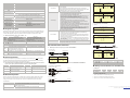
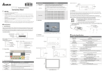
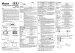
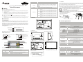
PANEL COMPONENT Shift Key It is used to select function keys F0 ~ F9 and other keys for special function. UP / Pg Up: It is used to increase the value or move up one page. Pg Dn / DOWN: It is used to decrease the value or move down one page. Left: This key is left direction key and it can be used to select the position of the value. Right: This key is right direction key and it can be used to select the position of the value. It is used to input a value or accept a programming command. F0 / F5: It is used to be constant 0 (F0) and 5 (Shift+F0) when it is in the system menu, the user can use it to define functions separately when they are in user page. F1 / F6: It is used to be constant 1 (F1) and 6 (Shift+F1) when it is in the system menu, the user can use it to define functions separately when they are in user page. F2 / F7: It is used to be constant 2 (F2) and 7 (Shift+F2) when it is in the system menu, the user can use it to define functions separately when they are in user page. F3 / F8: It is used to be constant 3 (F3) and 8 (Shift+F3) when it is in the system menu, the user can use it to define functions separately when they are in user page. F4 / F9: It is used to be constant 4 (F4) and 9 (Shift+F4) when it is in the system menu, the user can use it to define functions separately when they are in user page. http://www.delta.com.tw/industrialautomation/ Arrow Keys Terminal Panels Series! Instruction Sheet Enter Key Warning 3 3 3 3 3 3 3 Please read this instruction carefully before use. Switch off the power before wiring. The display panel of TP04 series is waterproof. But please prevent grease, corrosive liquids and sharp objects from contacting the TP04 series. The TP04 series require 24VDC input power. DO NOT connect input AC power supply to any of the RS-485 communication port; otherwise serious damage may occur. Check all the wiring again before switching on the power. DO NOT touch any terminal when the power is switched on. DO NOT touch any internal circuit in 1 minute after the power is switched off. Make sure the groud terminal is correctly grounded in order to prevent electromagnetic interference. Please use the fixed support accessory which is packed together with the product provided by Delta. DO NOT tighten the screws out of the normal torque specifications; otherwise serious damage may occur. 1.6 Installation EXPLANATION Function Keys Please insert TP04 series to the opening hole of panel and tighten the screws. However, if a firm mounting TP04 series to the panel is needed, please use the mounting fixed support accessory which is packed together with TP04 series, then insert the fixed support in the back and tighten the screws. If the fixed support is not installed well, Delta will not guarantee the waterproof function. The screw torque should be 4-5(kg-cm). DO NOT exceed this specification when tightening the screws; otherwise TP04 series may be damaged. Please leave sufficient space (more than 50mm) around the unit for heat dissipation. Do not install and mount TP04 series in the following environment. h A location subjected to Airborne dust, metallic particles, oil and smoke, corrosive or flammable gases and liquids. h A location where temperature and humidity will exceed specifications. h A location where vibration and shock will exceed specifications. The flat surface should be a UL Type 4 "Indoor Use Only" enclosure or equivalent (IP65 / NEMA4). Please refer to the figures below. Please leave sufficient space (more than 50mm) around the unit for heat dissipation. Thickness: 0.5~9.0mm 1.4 Back Panel X Introduction 1.1 Model Explanation Thank you for choosing Delta TP Series. TP04G-AS2 has the features of high resolution 128×64 dots and is able Y Function Specifications BATTERY SWITCH OR RS-485/422 to display 8×4 Chinese character. It provides multilingual display and two built-in communication ports, one is for RS-232 / RS-422 and the other is for RS-485. RS-232 and RS-485 can be used simultaneously. Besides, it also supports built-in RTC, communication / alarm LED indicators. The user can purchase program copy card (optional) to copy settings and programs quickly and save download time. Regarding the editing software, there are various STN-LCD Monochromatic The back-light automatic turn off time is 1 ~ 99 minutes (0 = do not turn off) (The back-light life is about 50 thousand hours at 25°C) 128x64 dots (W) x (H) = 72 x 40 (unit: mm); 3.00” (diagonal preferred) 10 levels of adjustment ASCII: (Code page 850) Alphanumeric (including European characters) Taiwan: (Big 5 codes) Traditional Chinese Fonts China: (GB2324-80 codes) Simplified Chinese Fonts 25 characters × 8 rows 16 characters × 8 rows 16 characters × 5 rows 16 characters × 4 rows ASCII: 5×8, 8×8, 8×12, 8×16 1. Power on indication (Blink for three times) 2. Communication error alarm 3. Special indication by user programming It will blink when transmitting program and communicating by using RS-232. Resolution Display Range Contrast Adjustment Nameplate Explanation MODEL : TP04G-AS2 POWER INPUT : 24Vdc 3.5W Language / Font 5 PIN terminal / Wire gauge: 12-24 AWG / Torque: 4.5 lb.-inch VX.XX TP04GAS2W6050004 DELTA ELECTRONICS, INC MADE IN XXXXXXX NOTE: The words of “MADE IN XXXXX” will be different due to the manufacturing location. Please refer to the actual product for exact description. Display Text Barcode and serial number Version TP04G-AS2 Backlight objects and images for the user’s requirements. Production model Power input spec. ITEM Screen Type Display Color 1.5 Dimension Front panel (unit: mm [inch]) Right side diagram (unit: mm [inch]) Model / Serial No. Explanation Alarm LED Indicator (RED) TP04GAS 2 W 6 05 0004 TP 04 G - AS 2 5×8 dots 8×8 dots 8×12 dots 8×16 dots Font Size RS-232/RS-422/RS-485 interface Reserved T: Text mode G: Graphic mode LCD Spec. Series name Production serial number Production weeks Production year (2006) 97.00 [3.82] 85.00 [3.35] Production plant (W: Wuijang; T: Taoyuan) Version RS-232 LED Indicator (Yellow) RS-485 / RS-422 LED Indicator (Green) Program Memory Serial Communication Port RS-232 (COM1) Production model 1.2 Product Outline 147.00 [5.79] Alarm LED Indicator Back panel Mounting dimension (unit: mm [inch]) RS-232 LED Indicator Displaying Area Extension Communication Port RS-422 (COM1) RS-485 (COM2) RS-485/RS422 LED Indicator Extension Interface Arrow Keys Escape / Exit Key Battery Cover 5 PIN Removal Terminal 85 [3.35] Enter Key It will blink when communicating by using RS-485 / RS-422. 256KB flash memory Unsynchronized transmission method: RS-232 Data length: 7 or 8 bits, Stop bits: 1 or 2 bits Parity: None/Odd/Even, Transmission speed: 9,600bps ~ 115,200bps RS-232: 9 PIN D-SUB male Unsynchronized transmission method: RS-485 / RS-422 Data length: 7 or 8 bits, Stop bits: 1 or 2 bits Parity: None/Odd/Even, Transmission speed: 9,600bps ~ 115,200bps RS-422: 9 PIN D-SUB male RS-485: 5 PIN removal terminal 1. Update firmware version 2. The slot for program copy card DC 3V battery for HMI Include DC 24V input and RS-485 communication input Shift Key Z Electrical Specifications Function Keys 1.3 Panel Function Explanation PANEL COMPONENT Alarm LED Indicator (RED) RS-232 LED Indicator (Yellow) RS-485 / RS-422 LED Indicator (Green) Displaying Area Escape / Exit Key 135~136.5[5.31~5.37] Thickness Range 0.5~9mm EXPLANATION Status 1: When power is on, LED will start to blink slowly Status 2: When there is an abnormal situation, LED will blink quickly along with an alarm sound. Specifications TP04G-AS2 Display Effective Display Area Monochromatic STN LCD (W) x (H) = 72 x 40 (unit: mm); 3 inches 5×8 dots 25 characters × 8 rows 8×8 dots 16 characters × 8 rows 128×64 8×12 dots 16 characters × 5 rows 8×16 dots 16 characters × 4 rows Set by Software, adjust the contrast by the press button in the function table LED Backlight: Automatic Turn-off Setting F0 ~ F9, ESC, SHIFT, ENTER and Arrow Keys 24V (3.5W Max.) Vertical view (Unit: mm) Display Resolution LED will blink when transmits program and communicates via RS-232. LED will blink when communicates via RS-485 / RS-422. Liquid Crystal Module display area. It is used to display current program status. It is used to cancel an incorrect input, or to exit a programming step. LCD Contrast Adjustment LCD Backlight Type Function / Numeric Keys External Input Power Specifications TP04G-AS2 Memory Capacity CPU RAM of System Communication Interface Waterproof Class of Front Panel Operating Temperature for Hardware Storage Temperature for Hardware 256K Byte Hitachi HD64F3064F 32K Byte COM1: RS-232 / RS422 COM2: RS-485 Vibration Shock Radiated Emission Electrostatic Discharge Immunity Radiated Immunity Electrical Fast Transient Weight / Dimensions Cooling Method SELECTIONS Copy Program IP65 / NEMA4 0 ~ 50°C; 20 ~ 90﹪RH (non-condensing) -20 ~ 60°C 5Hz≦f<9Hz = Continuous: 1.75mm / Occasional: 3.5mm 9Hz≦f≦150Hz = Continuous: 0.5g / Occasional: 1.0g 15g peak, 11ms duration, half-sine, three shocks in each direction per axis, on 3 mutually perpendicular axes (total of 18 shocks) CISPR11, Class A TP04 Settings EN61000-4-2 EN61000-4-3 EN61000-4-4 0.24kg; 147×97×35.5mm (Width(W) × Height(H) × Deep(D)) Natural Air Cooling [ Program Copy Card TP04 series provides Program Copy Card Function to copy user program, system function and passwords that is different from the copy program. It is used to copy the whole HMI environment settings and application programs to another HMI rapidly. Using Program Copy Card saves time and manpower. The operation is as follows. PLC Connection Definition: Program Copy Card → PCC, TP Series → TP (TP→PCC) Step 1 Step 2 Step 3 Step 4 (PCC→TP) Turn the switch on the PCC to TP→PCC Insert the PCC into the extension slot of TP Input the power to TP It will display “remove PCC” on the screen and power on again. Turn the switch on the PCC to PCC→TP Insert the PCC into the extension slot of TP Input the power to TP It will display “remove PCC” on the screen and power on again. Execution EXPLANAION application program from TP04. Transfer a program between two TP04 units. 1: transmit programs 2: receive programs When transmit programs and data between two TP04 units. Set one TP04 to “Receive Program” mode and the other TP04 to “Transmit Program” mode. Please use twisted pair wires to connect the two units via the RS-485 ports. There are 9 items that used to modify TP04 system settings: 1. Communication protocol: Setting the address of TP04, the control port of PLC, and the communication string for either RS-232 or RS-485. 2. Contrast: Adjust the contrast of LCM display screen. 3. Back-light: adjust the automatic turn off time of LCM. Setting range is 00 ~ 99 minutes. If set to 00, the LCM Back-light will not turn off. 4. Date and Time: It is used to set the TP04 built-in RTC including year, month, day, hour, minute, second and week. Also the internal battery capacity display is shown here. 5. Buzzer: Used to set the buzzer sound, normal mode or quiet mode. 6. Language Setting: Used to set the displayed language. English, Traditional Chinese, Simplified Chinese or user defined language. 7. Password setting: Used to set, enable, and disable the password function. If the password function is enabled, it will require the user to input a password before entering any system menu. The factory password is 1234. 8. Startup display: Used to select the TP04 startup display. User can select “user defined” to use the file that designed by TPEdit and download to TP04. 9. Comm. indicator: The user can determine if the RS-232 and RS-485 LEDs will blink or not during communication. There are three methods to connect to PLC: 1. Using TP04 serial communication port (COM1) RS-232: set 8-pin DIP switch to RS-485 mode and connect the cable (DVPACAB215 or DVPACAB230) to program communication I/O RS-232C of PLC. 2. Using extension communication port (COM2): set 8-pin DIP switch to RS-485 mode and connect 5-pin removal terminal of extension communication port to RS-485 of PLC with twisted pair. 3. Using extension communication port (COM2): set 8-pin DIP switch to RS-422 mode and connect four pins (6, 7, 8, 9) of 9 PIN D-SUB male to RS-422 of PLC with 4-wire cable. Execute the internal program that download from TPEdit or transmitted from other TP04 units. When program is in execution, the user can return to system menu by pressing Escape / Exit (Esc) key for 5 seconds. HMI Display Message Step 1 Step 2 Step 3 (TP→PCC) (PCC→TP) If the TP model type does not correspond with the model type of program of PCC, TP will display “TP series and PCC is different. Press Enter to Confirm TP seriesÆPCC. Press Esc to Exit”. TP will display “TP→PCC series Please wait!” during transmission. TP will display “Please Remove the PCC and Reboot” when transmission is completed. If there is no program in PCC, TP will display “The PCC is Empty. PCC→TP series is illegal”. Communication Connection TO PC (RS-232) 5 1 6 6 1 5 9 PC COM Port 9 PIN D-SUB female If the user forgot the password, the password can be cleared by using the following code: 8888. This universal Rx Tx GND code will clear the password and all TP04 series internal programs. The TP04 series will be reset to the factory settings by using this code also. Please pay close attention when using it. The password can be the alphabet from A to Z or the number from 0 to 9. But it must use the function keys F0 ~ F9 to input the password characters. Please refer to the following table. Function Key F0 / F5 F1 / F6 F2 / F7 Use Method Scrolls in a loop as follows 0→5→A→B→C→D→E→F→0 Scrolls in a loop as follows 1→6→G→H→I→J→K→1 Scrolls in a loop as follows 2→7→L→M→N→O→P→2 Function Key F3 / F8 F4 / F9 Use Method Scrolls in a loop as follows 3→8→Q→R→S→T→U→V→3 Scrolls in a loop as follows 4→9→W→X→Y→Z→4 series, it will enter into the startup display and then enter the user-designed program. Pressing Esc key and 13 9 5 6 1 25 PIN D-SUB Rx Tx GND 5V 1 2 5 8 6 7 The Pin definition of 9 PIN D-SUB 3 2 5 Tx Rx GND 2. RS-422 TP02 / 04G COM Port RS-422 9 PIN D-SUB male 6 7 8 9 Rx + Rx Tx + Tx - 3. DVPACAB630 (RS-422) 9 5 6 1 TO PLC MINI DIN TERMINAL 9 PIN D-SUB Rx+ Rx Tx+ Tx GND Tx Rx GND 3 4 TP02 / 04G COM Port RS-232 9 PIN D-SUB male MIT SUBISHI F X-PLC COM1 Port RS-422 8 PIN MINI DIN 6 7 8 9 5 7 4 2 1 3 Tx+ Tx Rx+ Rx SG 1 2 5 8 4 7 3 6 Switch between RS-422 / RS-485 (by using 8-PIN DIP switch) 8-PIN DIP Switch RS-485 RS-422 SW1 ~ SW4 SW5 ~ SW8 On Off Off On _ Battery Life and Precision of Calendar Timer TO PLC MINI DIN TERMINAL 9 PIN D-SUB TO PC or TP02 / 04G 9 5 described below. 6 1 Upload Program 3 2 5 Battery Life Temperature (°C) -20 0 20 60 Life (Year) 1.972 2.466 2.712 2.835 Precision of Calendar Timer EXPLANAION Use the connection cable (DVPACAB530) to connect the TP04 serial communication port RS-232 to a PC. Then use the TPEdit software to download an application program to TP04. Use the connection cable (DVPACAB530) to connect the TP04 serial communication port RS-232 to a PC. Then use the TPEdit software to upload an 2. At 25°C / 77°F, less than 52 seconds error per month. 2. DVPACAB2A30 holding on for 5 seconds can return to system menu. There are five selections in the system menu and are Download Program 2 3 5 TO PC or TP02 / 04G 1 4 5 8 1,2 3 6 1. RS-232 TP04G may connect to a DVP-PLC by using connection cable DVPACAB215 / DVPACAB230 / DVPACAB2A30 14 3 2 5 7 8 1 4 6 1 1. At 0°C / 32°F, less than -117 seconds error per month. When the user wants to startup TP04 series, a 24VDC power is needed. After applying 24VDC power to TP04 SELECTIONS TP02 / 04G COM Port 9 PIN D-SUB female 1. DVPACAB215 / DVPACAB230 ] Hardware Operation Tx Rx GND 9 PIN D-SUB 9 PIN D-SUB PLC COM1 Port 8 PIN MINI DIN TP02 / 04G COM Port 9 PIN D-SUB female TO TP02 / 04G 9 \ Password Function PC / TP COM Port 9 PIN D-SUB female TP04G may connect to a PC by using connection able DVPACAB515 PC or TP02 / 04G TP will display “PCC→TP series Please wait!” during transmission. TP will display “Please Remove the PCC and Reboot” when transmission is completed. PLC COM1 Port 8 PIN MINI DIN 4 Rx 2 5 Tx 4 5 8 GND 8 1,2 5V 7 TO TP02 / 04G ^ PC / TP CO M Port 25 PIN D-SUB female 2 Tx Rx 3 GND 7 4 5 6 8 20 9 PIN D-SUB TO PLC 3. At 55°C / 131°F, less than -132 seconds error per month. MINI DIN TERMINAL The content of this instruction sheet may be revised without prior notice. Please consult our distributors or download the most updated version at http://www.delta.com.tw/industrialautomation