1
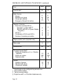
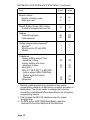
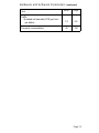
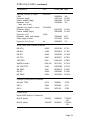
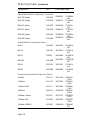
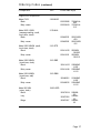
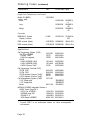
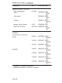
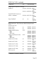
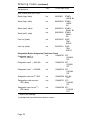
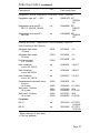
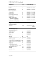
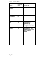
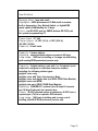
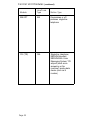
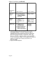
AT&T
MERLIN LEGEND
Communications System
Pocket Reference
TM
Copyright © 1991 AT&T
All Rights Reserved
Printed in U.S.A
AT&T 555-610-141
Issue 1
August 1991
Ordering Information
To order copies of this document:
Call:
AT&T Customer Information Center on 800-432-6600;
In Canada, call 800-255-1242
Write:
AT&T Customer Information Center
2855 North Franklin Road
P.O. Box 19901
Indianapolis, Indiana 46219-1385
For assistance when installing or programming the system:
Call:
National Service Assistance Center (NSAC) at
800-628-2888 or your authorized AT&T dealer
Notice
While reasonable efforts were made to ensure that the information
in this document was complete and accurate at the time of
printing, AT&T can assume no responsibility for errors. Changes
or corrections to the information in this document maybe
incorporated into reissues.
Trademarks
Accunet is a registered trademark of AT&T.
AUDIX is a trademark of AT&T.
Definity is a registered trademark of AT&T.
Magic on Hold is a registered trademark of AT&T.
Megacom is a registered trademark of AT&T.
MERLIN is a registered trademark of AT&T.
MERLIN LEGEND is a trademark of AT&T.
MERLIN MAIL is a trademark of AT&T.
MLX-20L, MILX-10D, MLX-10, and MLX-28D are trademarks of
AT&T.
SYSTIMAX is a trademark of AT&T.
ERRATA
MERLIN LEGEND™ Communications System
Pocket Reference
555-610-141
Ignore all references to the small processor module. The MERLIN LEGEND™ Communication
System offers only one processor module.
This processor module is referred to as a large processor
.
module in this document.
Page 2
Backboard Requirements: References to “Small system” should read “One expanison carrier” and
references to “large system” should read “Two expansion carriers.”
Pages 7-13
Hardware and software Parameters Table: Ignore the columns headed “Small.”
Page 14
Ordering Codes Table: The following Price Element Codes are not valid:
Small (Analog) - 6141-CUA
Small (Digital) - 6141-CUD
Small (Digital) - 6141-24D
Page 15
Ordering Codes Table: The following Price Element Code (PEC) is not valid:
Upgrade from Small to Large - 6140-USLA
Page 31
Memory Sizes: Ignore reference to small processor module.
October 1, 1991
Table of Contents
Design Benefits
Environmental Requirements
Control Unit Interfaces
Network Interface Requirements
FCC Registration
DOC Registration
Hardware and Software Parameters
Ordering Codes
Control Unit Modules
Adjunct Summary
Uninterruptible Power Source (UPS) Backup Times
Power Supply Unit Load Requirements
■ Unit Load Calculation Rules
■ Unit Load Rating of System Modules
■ Unit Load Rating of System Lines,
Telephones, and Adjuncts
System Features
Telephone and Operator Console Features
Reference Documents
1
2
4
5
6
6
7
14
30
38
48
49
49
51
52
53
56
70
i
Design Benefits
Modular components allow easy, cost-effective growth in both
size and function. For upgrades from the MERLIN® system family
of products, all analog MERLIN system telephones, as well as
wiring, can be reused. For upgrades from MERLIN II, certain
line/trunk and station modules can also be reused.
Menu-driven system programming maintains the customer’s
command of business operations.
Built-in 1200-bps modem allows fast access to the system by
customers, AT&T personnel, or authorized dealers from a remote
location for system programming and maintenance.
Flexible mode of operation saves upgrade costs by allowing
system configuration in one of three modes: Key, Behind Switch,
and Hybrid/PBX.
Connectivity to other systems in the Behind Switch mode
optimizes existing resources by permitting the system to work as
part of another MERLIN LEGEND™ Communications System,
System 25, System 75, System 85, Definity® 75/85, or other
communications systems. Also, the system control unit can
connect to another system’s control unit by using an off-premises
telephone (OPT) line, an analog tie trunk, or a digital tie trunk.
Digital 2.048-MHz bus supplies a 64-kbps channel on each of
the 216 time slots.
68000 Motorola CPU running at 10 MHz with zero wait states
provides fast system performance.
Memory data retention saves time by ensuring that system and
station programming information is retained for 12 to 30 days,
depending on the system configuration, in case of power failure or
system shutdown.
Integrated voice and data capabilities allow users to converse
while transmitting data at speeds up to 64 kbps.
DS1 interface can be configured for connection of either T1 or
ISDN for basic call control with the AT&T 4ESS PRI service
specifications.
ISDN S/T BRI protocol supports premier digital multiline
telephones (MLX) with superior display capabilities and supports
the ISDN 7500B Data Module for the connection of adjuncts.
Page 1
Environmental Requirements
Control Unit
45 lbs
90 Ibs
135 Ibs
Fully loaded basic carrier
Fully loaded 2-carrier
Fully loaded 3-carrier
Mean Time Between Failures
14” W x 23” H x 12” D
25” W x 23” H x 12” D
37” W x 23” H x 12” D
2.1 years
(mean or average time the
product/system is expected
to operate before any type of
failure occurs)
Mean Time Between Outages
4.0 years
(mean or average time the system
is expected to operate before a
failure affecting more than 25%
of stations or lines for more than
15 seconds occurs)
Backboard
Without SYSTIMAX™
Small system
■ Large system
With SYSTIMAX
■ Small system
■ Large system
■
4’ W x 3’ H x 3/4” D
6’ W x 3’ H x 3/4” D
5’ W x 4’ H x 3/4” D
7’ W x 4’ H x 3/4” D
Backboard Mounting Hardware Requirements
Wood screws
Wood surface
Masonry anchors
Concrete surface, brick, cinder block
Toggle bolts
Plaster, plasterboard
Sheet-metal screws
Sheet-metal surface
■ Hardware should have a combined pullout force of 650 Ibs.
■ When mounting to sheet-metal walls, attach to structural
members.
Location
Within 5 ft of dedicated AC power outlet (1 plug per carrier)
■ Within 1000 cable feet of telephones
■
Heat Dissipation
Fully loaded basic carrier
Fully loaded 2-carrier
Fully loaded 3-carrier
500 Btu/hr
1000 Btu/hr
1500 Btu/hr
Power Requirements
Basic carrier 117 VAC
2-carrier
117 VAC
3-carrier
117 VAC
Page 2
60 Hz ± 5% 3A
60 Hz ± 5% 6A
60 Hz ± 5% 9A
Environmental Requirements (continued)
Temperature Humidity Range
40°–104°F; 4–40°C (optimum temperature 60°F)
20%-80% relative humidity
Ventilation
1” on left side; 1” on right side; 12” above; 12” below
Cautions
■
■
■
■
■
■
■
Do not use switch control on AC outlet for control unit.
Use approved ground (AC receptacle for 3-prong plug).
Do not install control unit outdoors.
Do not place control unit near extreme heat (furnaces, heaters,
attics, or direct sunlight).
Do not expose control unit to devices that generate electrical
interference (such as arc welders or motors).
Do not place anything on top of carriers.
Do not install control unit under any device that may drip fluid,
such as an air conditioner.
Page 3
Control Unit Interfaces
Signaling
Channel
Rate
Audio/
Data
Rate
Interface
Applications
ISDN-BRI
S/T*
Digital switch to MLX
telephones
16 kbps
(D);
64 kbps
(B)
Digital switch to ISDN
7500B Data Module
64 kbps
(B and D)
DS1
Switch to the
following services
■
T1 — Emulated tie
trunk, loop-start,
and ground-start
■ ISDN-PRI services
Accunet®
switched
digital service,
Megacom®
WATS,
Megacom® 800,
Software Defined
Network (SDN)
64 kbps
RS-232C
Switch to PC
connected to system
programming
RS-232C port
2400 bps
or
1200 bps
2400
bps
or
1200
bps
Switch to AT&T model
572 printer, PC
with CAS, or CAT
connected to
RS-232C port
1200 bps
1200
bps
* Call handling derived from CCITT recommendation Q.931
Page 4
Control Unit Interfaces (continued)
Interface
Applications
ATL
Digital switch to
analog multiline
telephones
Signaling
Channel
Rate
Audio/
Data
Rate
40 kHz
3003400 Hz
Network Interface Requirements
Line/Trunk Type
Facility Interface
Code
Network
Interface
Loop-start
02LS2
RJ11C, RJ14C,
RJ21X
Ground-start
02GS2
RJ11C, RJ14C,
RJ21X
Direct Inward
Dialing
02RV2-T
RJ11C, RJ14C,
RJ21X
Off-premises
telephone
0L13C
RJ11C, RJ14C
Tie line
TL31M
RJ2GX
T1
04DU9-B
04DU9-C
RJ48C/X
ISDN-PRI
04DU9-B
04DU9-C
RJ48C/X
Page 5
FCC Registration
Registration Number
REN
Type
AS593M-72682-MF-E
1.5A
Multi-function
AS593M-72914-KF-E
1.5A
Key only
DOC Registration
DOC Certification No.
CSA Certification No.
230-4095A
LR-56260
Page 6
Load No.
6
Hardware and Software Parameters
Item
Allowed lists
Number of lists
Entries per list
Digits per entry
Applications
CAS
CAT
CMS
Number of lines/trunks (each)
Number of agents (each)
Number of external alerts (each)
Integrated Solution II
AUDIX Voice Power-lS II
Number of mailboxes (each)
Integrated Voice Power
Automated Attendant
Call Accounting System-lS II
System Programming and
Maintenance–IS II
MERLIN Attendant
MERLIN MAIL™ Voice Messaging
System
Number of mailboxes (each)
System Programming
and Maintenance–DOS
Automatic Route Selection
Fully programmable ARS tables
Entries per table
Entries across all tables
ARS patterns
Subpatterns per pattern
Routes per subpattern
Default tables
Small
Large
8
10
7
8
10
7
1
1
2
28
28
4
1
1
2
28
28
4
1*
300
1*
300
1*
1
1*
1
1
4
1
4
4
40
4
40
1
1
16
100
1600
18
2
6
4
16
100
1600
18
2
6
4
* AUDIX Voice Power-lS II and Integrated Voice Power
Automatic Attendant cannot be connected simultaneously.
Page 7
Hardware and Software Parameters (continued)
Small
Large
Callback calls in queue
64
64
Calling Groups
Number of groups
Members per group*
Groups per member
Delay announcements per system
Delay announcements per group
Groups per delay announcement
External alerts per group
Coverage groups per group
32
20
1
32
1
32
1
1
32
20
1
32
1
32
1
1
Carriers
†
Slots per basic carrier
Slots per expansion carrier
Carriers per system
Total slots available
5
6
3
1 7‡
5
6
3
17
Coverage Groups
Number of groups
Senders per group
Groups per sender
§
Receiver buttons per group
Groups per QCC receiver
32
56
1
8
30
32
144
1
8
30
Item
* QCCs cannot be members.
† The processor module must be placed in slot 00 in the basic
carrier.
‡ Software limits on the number of lines/trunks and stations
usually limit the number of carriers in a small system to 2 and
therefore the number of slots to 11.
§ For Hybrid/PBX systems, when queued call consoles (QCCs)
are used, the queue can also be assigned as a receiver but is
not counted in the 8-receiver maximum.
Page 8
Hardware and Software Parameters (continued)
Small
Large
Data hunt groups
Number of groups
Members per group
Groups per member
32
20
1
32
20
1
Digital data via ISDN 7500B Data Module
24
127
Direct Inward Dialing
Number of blocks
Number of trunks
2
24
2
80
1
40
1
130
1
56
1
144
16
50
48
50
Direct Station Selectors*
12
16
Disallowed Lists
Number of lists
Entries per list
Digits per entry
8
10
11
8
10
11
DS1 modules
1
3
Item
Directories
System Directory (System Speed Dial)
Number of directories
Listings per directory
Extension Directory
Number of directories
Listings per directory
Personal Directory
Number of directories
Listings per directory
Fax machines with Message Waiting
16
†
†
16
* Two per MLX module; the analog multiline display console has
a built-in DSS.
† The system can support more than 16 fax machines, but those
in excess of 16 cannot use the fax message-waiting indication.
Page 9
Hardware and Software Parameters (continued)
Small
Large
Lines/trunks*
24
80
Night Service
Groups
Members per group
Groups per member
Emergency Allowed List entries
8
56
8
10
8
144
8
10
Item
*
†
‡
§
Operator Consoles
Direct-line consoles (DLCs)
MLX-20L™ or MLX-28D™ †
BIS-22D, BIS-34D, or System Display
Console ‡
QCCs †
Combination of DLCs and QCCs
Number of consoles per module
6
8
8
4
8
2
8
4
8
2
Paging system ports (loop-start only)
3
3
Park codes
8
8
Personal lines
56
64
Personal Speed Dial §
Entries per single-line or 5- or 10-button
telephone
Entries per system
Digits per entry
24
880
16
24
1200
16
Pickup
Number of groups
Members per group
Groups per member
30
15
1
30
15
1
Lines/trunks can be configured as personal lines.
Two per MLX module.
Two per analog module.
Single-line and 5- or 10-button telephones only.
Page 10
Hardware and Software Parameters (continued)
Item
Small
Large
Pools (trunk groups)
Maximum number of pools
Maximum number of trunks in a pool
11
24
11
80
Pool buttons
56
64
Ports (not achievable simultaneously)
Delay announcements
Digital data via ISDN 7500B
Data Module
Paging
Voice and data (physical ports)
Voice Announce to Busy stations
Voice-mail interface*
Total ports †
32
32
24
3
56
28
20
80
127
3
144
127
20
224
Power failure transfer telephones
6
20
* Although the system software supports up to 24 voice mail
interface (VMI) ports, all the VMI ports must be in the same
calling group, and the maximum number of stations in a calling
group is 20.
† The large system is said to have a total capacity of 224 (80 CO
lines/trunks plus 144 stations). However, these are physical
jacks. Each MLX station jack represents 2 logical endpoints
(ports). For example, an MLX telephone with a Multi-Function
Module (MFM) plugs into only 1 station jack, but the jack
supports the telephone and whatever is connected to the MFM
(fax machine, answering machine, etc.). The 1 station jack is
supporting 2 endpoints.
Although it has only 1 jack, the 100D module can serve up to
24 endpoints. Therefore, the entire large system can be
configured to connect up to 80 lines/trunks and 255 station
endpoints, a total of 335 endpoints.
This total of 335 endpoints exceeds the system’s capacity of
216 time slots. If more than216 endpoints are in use at the
same time, blocking can occur.
Page 11
Hardware and Software Parameters (continued)
Small
Large
Remote Access
Number of barrier codes
Digits per code
16
4
16
4
Shared System Access (SA) buttons
Number of shared buttons per SA
16
16
Stations
Total physical jacks
Total endpoints
56
56
144
255
1
1
1
1
1
1
56
136
28
16
127
48
24
56
127
144
Item
System programming equipment*
MLX-20L™
RS-232 port for PC with SPM
Modem
Telephones
Analog multiline without Voice
Announce to Busy
Analog multiline with Voice
Announce to Busy
MLX-20L†
MLX-10,™ MLX-10D,™ or MLX-28D
(with or without ISDN 7500B Data
Module or Multi-Function
Module) ‡
Single-line
* Remote system programming overrides on-site system
programming unless an on-site backup or restore procedure is
taking place. The system sends a message that a remote
connection is established before terminating an on-site system
programming session.
† Total includes the MLX-20L telephone used for system
programming.
‡ An MFM and an ISDN 7500B Data Module cannot be
connected to the same telephone at the same time.
Page 12
Hardware and Software Parameters (continued)
Small
Large
Traffic
Hundred call seconds (CCS) per hour
per station
7.0
6.0
Two-party conversations
40
108
Item
Page 13
Ordering Codes
Component
PEC
Comcode App
Control Unit
Small (Analog)
Basic carrier and housing
Power supply module
Processor (small)
Feature module (small)
408 GS/LS
6141-CUA
Small (Digital)
Basic carrier and housing
Power supply module
Processor (small)
Feature module (small)
008 MLX
800 GS/LS
6141-CUD
Small (Digital)
Basic carrier and housing
Power supply module
Processor (small)
Feature module (small)
008 MLX (3)
800 GS/LS
400 GS/LS/TTR
6141-24D
Large
6140-CUL
Basic carrier and housing
Power supply module
Processor (large)
Feature module (large)
Upgrade from Mll to
6140-UDLA
Large (Digital)
Cover
Processor (large)
008 MLX
Feature module (large)
MLX-20L telephone (choose one):
Black
White
Expansion cover
(zero, one, or two)
Page 14
106388614
105743801
105711972
105711998
106064678
403E
391A1
517A23
517A24
517A26
106388614
105743801
105711972
105711998
105628010
105627996
403E
391A1
517A23
517A24
517A21
517A19
106388614
105743801
105711972
105711998
105628010
105627996
105627988
403E
391A1
517A23
517A24
517A21
517A19
517A18
106388614
105743801
106215155
106064660
403E
391A1
517A27
517A25
106388234
106215155
105628010
106064660
16A
517A27
517A21
517A25
105685465
7713DO1A003
7713DO1A264
17A
105685473
106388259
Ordering Codes (continued)
Component
PEC
Upgrade from MII to Large
Cover
Processor (large)
Feature module (large)
Expansion cover
(zero, one, or two)
6140-UULA
Upgrade from Small to Large
Processor (large)
Feature module (large)
6140-USLA
Expansion Unit
Expansion carrier and housing
Power supply module
61490
Expansion Unit Cover
n/a
Comcode App
106388234
106215155
106064660
106388259
16A
517A27
517A25
17A
106215155
106064660
517A27
517A25
106388630
105743801
403F
391A1
106388259
17A
Line/Trunk and Station Modules
008 (ATL)
61485
105351092
51703
008 MLX
61486
105628010
517A21
008 OPT
61489
106387525
517A28
012 (T/R)
61487
106397631
517E13
100D (DS1)
61491
105461560
517B15
400EM (tie trunk)
8303-200
105311401
517A14
400 GS/LS/TTR
61483
105627988
517A18
408 GS/LS
61481
106064678
517A26
800 DID
61488
105628002
517A20
800 GS/LS
61484
105627996
517A19
400 (with TTRs)
61379
105408892
517B12
408 LS
61482
105512495
517C1
800 LS
61384
105351100
517B4
MLX-10 (black)
3156-02B
105685440
MLX-10 (white)
3156-02W
105685457
7712D01A003
7712DOlA264
Vintage Line/Station Modules
Telephones
Digital/ISDN Multiline Telephones
Page 15
Ordering Codes (continued)
PEC
Component
Comcode App
Digital/ISDN Multiline Telephones, continued
MLX-10D (black)
3156-03B
105688303
MLX-10D (white)
3156-03W
105688311
MIX-20L (black)
3156-05B
105685465
MIX-20L (white)
3156-05W
105685473
MLX-28D (black)
3156-04B
105688329
MLX-28D (white)
3156-04W
105688337
7712D02A003
7712D02A264
7713D01A003
7713D01A264
7713D02A003
7713D02A264
Analog Multiline Telephones (black)
MLC-5
3168-MLC
105515332
7312H01A003
BIS-10
3165-10B
105161061
7313H01A003
BIS-22
316W28
105188809
7314H01A003
BIS-22D
3166-DSB
105630420
7315H01B003
BIS-34
3167-34D
105167027
7317H01A003
BIS-34D
3167-DSB
105630529
7317H01B003
Z7302H01
D-003
Z7303H01
D-003
Z7309H01
C-003
Z7305H01
B-003
Vintage Analog Multiline Telephones (black)
5-Button
3160-111
105217426
10-Button
3161-172
105217509
10-Button HFAI
3161-161
105371942
34-Button
3162-412
103842050
34-Button Deluxe
3162-417
105217715
Z7305H02
D-003
34-Button BIS
3162-BIS
103981965
Z7305H03
D-003
34-Button BIS/DIS
3162-DIS
103981981
7305H04C003
Page 16
Ordering Codes (continued)
Component
PEC
Comcode App
Single-Line Telephones
Model 7102
Black
3185-MWR
105335285
105330419
Misty cream
Model 2500 YMGK
(message waiting, recall,
touch-tone, desk)
Black
3178-NHL
105480578
105480560
Misty cream
Model 2500 MMGK (recall,
touch-tone, desk)
Black
105414130
105414122
105414155
105414148
2500MMG
J-003
2500MMG
J-215
3101-EBW
105480081
Misty cream
Model 500 MM
(rotary, desk)
Black
2500MM
GK-003
2500MM
GK-215
3101-EBD
Misty cream
Model 2554 MMGJ
(touch-tone, wall)
Black
2500YMGK
-003
2500YMGK
-215
3101-ETR
Misty cream
Model 2500 MMGJ
(touch-tone, desk)
Black
7102A01A003
7102A01A215
105480032
2554MMG
J-003
2554MMG
J-215
3100-ORD
103870234
Ivory
103870226
Beige
103870267
500MM03
500MM50
500MM60
Page 17
Ordering Codes (continued)
Component
PEC
Comcode App
Single-Line Telephones, continued
Model 554 BMPA
(rotary, wall)
Black
3100-ORW
103823498
Ivory
103823506
Beige
103823555
554BMPA
-3
554BMPA
-50
554BMPA
-60
Consoles
MERLIN® II System
Display Console
61392
105229744
7318H01A003
DSS console (black)
3156-DCB 105685481
604A1-003
DSS console (white)
3156-DCW 105685499
604A1-264
Applications
Call Accounting System (CAS)
CAS PIus LEGEND
Custom Tariff*
CAS Plus upgrade
CAS/H
CAS/H LEGEND 100S
CAS/H LEGEND 200S
CAS/H Custom Tariff*
Call Accounting Terminal (CAT)
CAT/B 150S
CAT/H 150S
CAT/B update (Custom Tariff)*
CAT/H update (Custom Tariff)*
Call Management System (CMS)
5 1/4” floppy disk
3 1/2” floppy disk
Board
1201-DR1
12010
12009
406362244
406158444
406158394
1201-H10
1201-H20
12050
405799255
405799289
405799420
3600-023
3600-024
406478800
406478818
406478792
406478784
36023
36024
1207-100
106496540
106496532
8301-100
106198815
MERLIN LEGEND integrated Solution II
AUDIX Voice Power-lS II
1234-VR1 106491608
AVP2.1 for LEGEND
1234-SR1 106491590
LEGEND Integ SW
IVP4SS R1 .2
1234-BR1 106491616
IVP4 Board LEGEND
8306-100 106248651
* Consult AT&T or an authorized dealer for other area-specific
information.
Page 18
Ordering Codes (continued)
Component
PEC
ComcOde App
Applications, continued
Integrated Voice Power
Automated Attendant
SAA LEGEND
IVP4SS R1 .2 LEGEND
IVP4 Board LEGEND
Call Accounting System lS II
System Programming and
Maintenance lS II
MERLIN Attendant
Hardware
Documentation
MERLIN MAIL™ Voice Messaging
System for the MERLIN LEGEND
Communications System
Two-port
MERLIN MAIL unit
Remote maintenance device
Four-port
MERLIN MAIL unit
Remote maintenance device
Two-port line card (R2)
(upgrade from two to four)
1234-AA1
1234-BR1
8306-100
1201-U12
61496
106491624
106491616
106248651
406478537
106496565
6125-ATT
406221499
106431265
6107-005
406467910
406466193
6107-006
6107-007
System Programming and
61495
Maintenance (SPM) for the
MERLIN LEGEND
Communications System (MS-DOS*)
406467902
406466193
406464750
106492655
Adjuncts/Adapters
System Adjuncts/Adapters
Auxiliary Power Unit 9024
Channel service units (CSUs)
ESF T1
61416
406467142 9024
2152-ESF 405616293
Cable (8 mod, wire wrp)
21555
Cable (8 mod, 15-pin sub)
21554
Stand-alone wall mount
21545
305010171
-001
406012609 513861312
-505
406012591 513823015
-50 Ft
405970104 380100213001
* Registered trademark of Microsoft Corporation
Page 19
Ordering Codes (continued)
Component
PEC
System Adjuncts/Adapters, continued
Channel service units (CSUs)
2152-15T
551 T1 L1
Power unit
Unit
Cord
21530
Stand-alone wall mount
21545
Cordless Telephones
Model 5320
62523
Electrostatic discharge (ESD)
suppression kits
D-181574
D-181589
0-181590
0-181591
0-181593
EMI filter
lROB unit — analog multiline*
n/a
n/a
n/a
n/a
n/a
ISDN 7500B Data Module
Stand-alone power supply
Multiple mounting
7500A upgrade kit
Magic-on-Hold® player
Modem 2224G
403768179 305-10097001
404242639 KS22911L1
DW4A-SE
103985660
10FT IP
405970104 380100213001
3103-CLS 105543516 CS6300U1
1A-229
DA-5 Digital Voice Announcer
IROB unit — MLX*
Comcode App
405745811 ANNCRDA-5SL
DI
0181574
D181589
D181590
0181591
0181593
Z200A
406106583 343 CA 0A
32918
6XIN
106417447 505A ASSY
32919
0A WD
2164-BDM 105657654 Z7500B-L1
405509852 WP90110
21625
L7
105441166 Z77A
21626
105688501 D182208
21627
3128-010
405143827 DECKMMP/
RCA PR
2224-CEO 105659965 2224C-L1
D/2
105179329
105201891
105201909
105201917
105201933
* Any multiline off-premises telephone must have an appropriate IROB
protector at the control unit location and at the off-premises location.
Page 20
Ordering Codes (continued)
Component
PEC
Comcode App
System Adjunct/Adapters, continued
Music Coupler
61398
406143925
PagePac* 6
5323-006
405701277
PagePac 6 Plus
5323-008
405701608
PagePac 20 Power Mate †
with three speakers
Ring generator unit
5323-005
5323-001
61388
403308026
403308067
105213201
SMDR Printers
475 (80-column, serial)
3330-475
403318942
476 (132-column, serial)
3330-476
403818495
572 (80-column, serial)
3333-572
406152983
Uninterruptible Power Source (UPS)
2403-050
500 VA (15 min)
105610141
ASSYK23395
L3
22052-006
PG PC
22052-000
PG PC6
ADP06
ADP06
129B RING
GEN
4758510BR2
4761550BR2
5729500DR
10IN
24035
105610174
Universal Paging Access Module 58500
(UPAM)
n/a
TAM-B
n/a
PRS-48
WMT-1A
n/a
†
ZoneMate 9
53505
Dialer unit
405891698
515 UPS005C111
ERG
W/BAT005E5
KIT-UPAM
405899972
405742735
405891680
D181900
D181900
D181900
404057911
DIAL UNIT9ZONE
CNTL
22050020
Reserve (1 hr)
Control unit
405024134
* Registered trademark of Dracon, a division of Harris Corporation
† Trademark of Dracon, a division of Harris Corporation
Page 21
Ordering Codes (continued)
Component
PEC
System Adjuncts/Adapters, continued
53506
ZoneMate 39
Dialer unit
Control unit
Comcode App
404057929 39 ZONE
SELECT
405024134 CNTL_22050020C
External Alerts
Loud external ringer
31016A
E1CM-type
Gray
31019A
103117016 RINGERL1AMP49
102872934 RINGERE1CM-49
102917952 RINGERE1CM-50
Ivory
61211
D-181233
102992252 290A
ADPTR
102872934 E1CM-49
102988466 1049A
103938494 CORDD4cH87-25
Bell
61212A
403349962 BELLKS23053
L1
Horn
61213A
403349970 KS23053
L2
Deluxe horn
61223A
406207217 SIG
THET4-1
Strobe
61221A
403319197 STROB
SCOPE
Chime
61222A
405136060 CHMCHBT2
S1
E1CM ringer and parts
290A adapter
Ringer
Mounting plate
Cord
Supplemental Alerts
Page 22
Ordering Codes (continued)
Component
PEC
Comcode App
Telephone Adapters
General Purpose Adapter
(analog)
Multi-Function Module
(digital)
Supplemental Alert Adapter
(SAA)
2301-GPA 103977997 Z1C
3156-MFM 105736474 540A1
2301-SSA 105031199 ADPTR856A
Telephone Adjuncts
Headset Adapter
3164-HFA 105752042
Headset Adapter
62524
Single-line telephones
4A Speakerphone
Power unit
3120-02W
105471304
102139938
Block connector
102434925
Adapter for single-line telephone
102813888
Adapter for multiline telephone
102949013
Transmitter
103971891
Black
103873873
Ivory
103873881
Green
103873899
Beige
103873907
White
103873964
S202A Speakerphone
Black
Misty cream
ADPTR502C-003
ADPTRKS23552
4A
PWR UNIT85B1
BLK CON82B-49
ADPTR223C
ADPTR2230 IP
TRMR680AF-03
LSPK108AA-O3
LSPK108AA-5O
LSPK108AA-51
LSPK108AA-6O
LSPK108AA-58
3152-008
105721088
105721096
TELS202A003
TELS202A215
Page 23
Ordering Codes (continued)
Component
PEC
Comcode App
Telephone Adjuncts, continued
S203A Speakerphone
Black
3131-008
106058340 MODS203A003
106508365 MODS203A215
106284011 BRKTS203 WL
ST
103966396 Z34A
Misty cream
Bracket
Message Waiting Indicator
Hands Free Unit (HFU)
31032
3163-HFU 103953790 MODS102A185
Headsets
Analog Multiline Telephones
Supra*
3122-011
3122-012
3122-013
†
StarSet II
3122-001
3122-002
3122-003
3122-004
403350085 HDSTKS22990
L1
403350077 HDSTKS22990
L2
403350051 HDSTKS22990
L3
403241540 HDSTKS22915
L1
403241557 HDSTKS22915
L2
403241565 HDSTKS22915
L3
403350093 HDSTKS23080
L1
* Trademark of Plantronics Corporation
† Registered trademark of PIantronics Corporation
Page 24
Ordering Codes (continued)
Component
PEC
Comcode App
Analog Multiline Telephones, continued
StarMate* E
3122-204 403412307 HDSTKS23080
L4
3122-214 403973431 HDSTKS23080
L5P
Digital/ISDN (MLX) Telephones
StarSet II—StarMate-E
3122-304 405211723 HDSTKS23080
L7
Supra—StarMate-E
n/a
n/a
HDSTKS23080
L8
MLX Telephones—Miscellaneous
Add-Ons/Replacement
Parts
Handsets and Cords
Handset (black)
n/a
106050065
K2S1-003
Handset (white)
n/a
106053408
K2S1-264
Handset, amplified hearing
Black
White
Misty cream
31052
Handset, amplified push to listen
Black
White
Misty cream
31053
Handset cord (9’, black)
n/a
105635429 H4DU-003
9Ft
Handset cord (9’, white)
n/a
105701809
H4DU-264
9’BULK
Handset cord (12’, white)
n/a
102402609
H4DU-264
12’IP
Handset cord (12’, black)
n/a
102401445
H4DU-3
12Ft IP
Handset cord (25’, black)
n/a
105523866
H4DU-3 25’
DSS line cord (2’)
n/a
106187545 CORD
D8AC-87
105581896 K6S2-003
106248248 K6S2-264
105581904 K6S2-215
106382344 K8S2-003
106382369 K8S2-264
106382351 K8S2-215
* Trademark of Plantronics Corporation
Page 25
Ordering Codes (continued)
PEC
Comcode App
Stand (large, black)
n/a
846320851
Stand (large, white)
n/a
846320844 STANDLARGE
WH
Stand (small, black)
nla
846320810 STANDSMALL BL
Stand (small, white)
n/a
846320802 STANDSMALL
WH
User tray (black)
n/a
846320240
USER
TRAY
DWR B
User tray (white)
n/a
846320232
USER
TRAY
DWR W
Component
Desk Stands and User Trays
STANDLARGE BL
Designation (Button Assignment) Cards and Covers
Designation card* —
MLX-10, MLX10D
n/a
106448707 KITD182459
PRT
Designation card* — MLX-20L
n/a
106448723 KITD182461
PRT
Designation card* — MIX28D
n/a
106448715 KITD182460
PRT
Designation card set †— DSS
n/a
106448756 KIT Set
DSS
Designation card covers†—
DSS (black)
n/a
Designation card covers †—
DSS (white)
n/a
.
* Twelve per package
† Includes both top and bottom cards or covers
Page 26
106448731 KITD182462
PRT
106448749 KITD182463
PRT
Ordering Codes (continued)
Component
PEC
Comcode App
Designation (Button Assignment) Cards and Covers, continued
Designation card set* — QCC
n/a
106561673 KITD182562
PRT
†
Designation card covers —
MLX-10, MLX10D, MLX20L
n/a
106448681 KITD182457
PRT
Designation card covers†—
MLX-28D
n/a
106448699 KITD182458
PRT
Analog Multiline Telephones—Miscellaneous Add-Ons
Desk Stands and Wall Mounts
Adjustable desk stand,
10-button
32002
103746855
11A
Adjustable desk stand,
34-button
32003
103746863
11C
Fixed desk stand,
5-& 10-button
32004
103746848
10A
Desk stand/wall
mount 14A, BIS-10
n/a
103804290
14A-003
Desk stand/wall
mount 14B, BIS-22
n/a
103964458
14B-003
Desk stand/wall
mount 14C, BIS-34
n/a
103979837
14C-003
Fixed desk stand and wall mount,
5-button
Kit of parts
32000
103804290
10A
32000
103995882
D-1 81230
Wall mount, 10-button
Kit of parts
32001
32000
103747846
103995882
201A
D-1 81230
Wall mount, 34-button
Kit of parts
32006
32000
103747853
103995882
203A
D-181230
Faceplates
BIS-10
n/a
105203186
BIS-22
n/a
105336986
KIT PRTSD-181582
KIT PRTSD-181784
* Eight cards per kit (four sets)
† Four per package
Page 27
Ordering Codes (continued)
Component
PEC
Comcode App
Faceplates, continued
BIS-22D
BIS-34 and BIS-34D
n/a
n/a
105690762
105203194
D-1 82210
D-181583
10-button BIS
n/a
105336978
D-181785
22-button BIS
n/a
105336960
D-181784
22-button BIS with display
n/a
105690770
D-182211
34-button BIS
n/a
105336956
D-181783
Display console (FM1)
(includes one faceplate)
n/a
105299754
D-181727
Display console (FM2 & R3)
(includes one faceplate)
n/a
105486252
D-182041
Button Label Sheets
Single-Line Telephones—Miscellaneous Add-Ons
Ground-Start Button
31021
405792839 Key-KS
23566L1
110AB1-100JP12
110A1 trough
D-Rings
D8W cords
Parts list
n/a
n/a
104409396
104407960
n/a
n/a
n/a
842139248
103786802
n/a
SYSTIMAX™ MERLIN® Wiring Kit
110A1 trough (5)
110AB1-100JP12 modular block (2)
110AB1 110 punch down block (1)
D-Rings (6)
110P8A5B patch cords
(12—4-pair—5-ft. patch cords)
D8W cords (24—14 ft.)
Template
Instruction sheet
Parts List
3103-MER
106393671
n/a
n/a
n/a
104407960
104409960
103823845
842139248
KS23566L1
Miscellaneous Parts
Interconnect Wiring Kit
Page 28
n/a
n/a
846619989
n/a
103786802
n/a
n/a
846613933
846613941
n/a
846623924
NOTES
Page 29
Control Unit Modules
Module
Line/Trunk
Type
Station Type
Processor
N/A
N/A
Power supply
N/A
N/A
008
N/A
Analog multiline
telephone; Call
Management System;
analog data via a modem
008 MLX
N/A
MLX telephone; digital
data device (such as the
ISDN 7500B Data
Module)
Page 30
Specifications
Memory Sizes: large and small
Highlights: 68000 processor at 10 MHz, built-in modem;
built-in diagnostics; Key, Behind Switch, or Hybrid/PBX
mode option; RAM backup for 12 days
Ports: top RS-232C port for SMDR; bottom RS-232C port
for system programming PC
Power input: 117 VAC
Power output: +5 VDC (10 A), -5 VDC (2.50 A),
-48 VDC (2.05A)
Capacity: 54 unit loads
Capacity: 8 analog stations
Signaling: analog multiline telephone protocol (40 kbps)
Loop range: 1000 feet in-building or in-range out-of-building
(with analog IROB protectors) service only
Capacity: 8 digital stations, each with 1 or 2 endpoints (each
endpoint is assigned an individual extension number),
including the following station types:
■ digital voice only
■ digital voice with Voice Announce to Busy
■ digital voice and digital data (via ISDN 7500B Data Module)
■ digital voice and MFM
■ digital data only (ISDN 7500B Data Module)
Signaling: ISDN-BRI S/T protocol (two 64-kbps B channels,
one 16-kbps D channel) on a passive bus
Power: 48-VDC phantom power to telephone; 48 VDC over a
separate pair (7-8) to an operator DSS console
Loop range: 1000 feet, in-building and in-range out-ofbuilding (with MLX lROB protectors) service only
Page 31
Control Unit Modules (continued)
Module
Line/Trunk
Type
008 OPT
N/A
On-premises or offpremises single-line
telephone
012 (T/R)
N/A
Single-line telephone;
MERLIN Attendant;
MERLIN MAIL Voice
Messaging System; T/R
adjunct (such as an
answering or fax
machine); analog data
device (such as a
modem)
Page 32
Station Type
Specifications
Capacity: 8 T/R stations* on 2-way voice transmission path
with support for telephones with message-waiting LEDs;
2 TTRs
Notice to Telco: Meets FCC Class C
Ringing current: 105-Vrms, 30-Hz sinusoidal ringing
superimposed on -48 VDC; a ring generator must be installed
in the power supply module of each carrier that has a
008 OPT module.
REN: < 1.0 per port
Disconnect signal: 900 ms (T/R short for answering
machines, G3 fax, etc.)
Switchhook flash detection: 300-1200 ms
Loop resistance: Serves 2-wire loops to 1300 ohms,
including stations
Capacity: 12 T/R stations on 2-way voice transmission path
with support for telephones with message-waiting LEDs, 2
TTRs
Power: 21-VDC, 600-ohm battery source
Ringing current: 105-Vrms, 30-Hz sinusoidal ringing
superimposed on -48 VDC; a ring generator must be installed
in the power supply module of each carrier that has a 012
module.
REN: < 1.0 per port
Disconnect signal: 900 ms (T/R short for answering
machines, G3 fax, etc.)
Switchhook flash detection: 300-1200 ms
* The system recognizes the OPT module as an 012 module
having 12 ports. However, the OPT module has only 8 jacks.
Therefore, each installed OPT module decreases the system’s
capacity by 4 ports.
Page 33
Control Unit Modules (continued)
Line/Trunk
Type
Station Type
100D
T1 or PRI
N/A
400 †
Loop-start
and TTR
Power failure transfer
(PFT) telephone
400EM
Tie trunk
N/A
400 GS/LS/TTR
Loop-start
or groundstart and
TTR
PFT telephone; button
needed for ground-start
PFT telephone
Loop-start
Analog multiline
telephone; Call
Management System;
PFT telephone
Loop-start
or groundstart
Analog multiline
telephone; Call
Management System;
PFT telephone
Module
†
408
408 GS/LS
† Although these MERLIN II modules are supported in the
MERLIN LEGEND Communications System, the 400 GS/LS and
the 408 GS/LS are the recommended modules.
Page 34
Specifications
Capacity: 24 Iines/trunks for voice and analog data or 23
lines/trunks for voice and data with 1 channel used for
signaling
Mode: multiplexes 24 or 23 Iines/trunks into 1 facility and
demultiplexes 1 facility into 23 or 24 lines/trunks
Speed: Up to 64 kbps
Signaling: DS1 over 4-wire; T1 uses robbed-bit or commonchannel; PRI has ISDN-PRI (23 B + D)
Capacity: 4 lines/trunks, 4TlTRs, 1 PFT telephone
Signaling: Loop-start
Capacity: 4 tie lines
Method of completion: automatic start, immediate-start,
wink-start, or delay-dial-start
Signaling: E&M type 1S, type 1C, type 5
Capacity: 4 lines/trunks, 4 TTRs, 1 PFT telephone
Signaling: Loop-start or ground-start, optioned per port
Capacity: 4 Iines/trunks, 8 stations, 1 PFT telephone
Station signaling: analog multiline telephone (40 kbps)
Line/trunk signaling: Loop-start line/trunk; analog voice
Loop range: 1000 feet, in-building and in-range out-of
building (with analog IROB protectors) service only
Capacity: 4 Iines/trunks, 8 stations, 1 PFT telephone
Station signaling: analog multiline telephone (40 kbps)
Line/trunk signaling: loop-start or ground-start Iine/trunk
(optional per port); voice
Loop range: 1000 feet, in-building and in-range out-ofbuilding (with analog IROB protectors) service only
Page 35
Control Unit Modules (continued)
Module
Line/Trunk
Type
Station Type
800 ‡
Loop-start
PFT telephone
800 DID
Direct
Inward
Dialing
N/A
Loop-start
or groundstart
PFT telephone; button
needed for Ground-start
PFT
.
800 GS/LS
‡ Although this MERLIN II module is supported in the MERLIN
LEGEND Communications System, the 800 GS/LS is the
recommended module.
Page 36
Specifications
Capacity: 8 lines/trunks, 2 PFT telephones
Signaling: loop-start
Capacity: 8 trunks, 2 TTRs
Transmission: incoming calls only; 2-way (1-pair) fixed
impedance to DID trunks; no outgoing calls
Signaling: loop-reverse battery; wink-start or immediatestart; accepts touch-tone dialing
Capacity: 8 lines/trunks, 2 PFT telephones
Signaling: Loop-start or ground-start
Page 37
Adjunct Summary
Equipment
Type
Specifications
Alerts (AC)*
■
■
Alerts (DC)
■
■
Answer/
Record
Machine*
■
■
■
Any audible or visual
alert that operates on
20-30-Hz ringing
signals
Associated with a
specific station
(supplemental alert)
or works on a programmed line/trunk port
(external alert)
External
Ringer—Loud
External Ringer
Any audible or visual
alert that operates on
48-VDC ringing signals
Associated with a
specific station
(supplemental alert)
or works on a programmed line/trunk port
(external alert)
Alert bell
Alert horn
Alert strobe
Alert chime
Alert deluxe horn
Alert switch
Industry-standard
machine
Low ringer equivalence (less than 0.15 or
< 1.0 total REN for T/R
port)
Ability to recognize
600-ms disconnect
signal or other means
of automatic disconnect (such as voice
reset disconnect timer,
fixed recording time)
Model 1330
answering
machine
Model 1531
Remote
Answering
System telephone
* Cannot be connected to a QCC.
Page 38
AT&T Products
Interface
*
LS or
GS/LS
T/R
MFM
GPA
SAA
Line
Jacks
012
Station
Jack
Digital
Station
Jack
Analog
Station
Jack
Analog
Station
Jack
Requires Universal Paging Access Module (UPAM) to provide
48 VDC.
Page 39
Adjunct Summary (continued)
Equipment
Type
Cordless
Telephone*
Specifications
■
■
AT&T Products
Must have touch-tone
dialing capability when
connected via MFM;
rotary or touch-tone
dialing can be used on
T/R port.
Single line
5320 Cordless
Telephone
5200 Cordless
Telephone
5500 Cordless
Telephone
Credit Card
Verification
Terminal*
■
Must have touch-tone
dialing capability when
connected via MFM;
rotary or touch-tone
dialing can be used
on T/R port.
N/A
Dial
Dictation*
■
A device that requires
contact closure can be
used on LS/GS line jack
only with UPAM
N/A
Direct
Station
Selector
■
A maximum of 2
DSSs can be connected to an operator
console.
A 329A power unit must
be added to an
operator console
having 2 DSSs.
Connects to “DSS” jack
on operator console
N/A
■
■
* Cannot be connected to a QCC.
Page 40
Interface
LS or
GS/LS
T/R
MFM
GPA
SAA
Line
Jacks
012
Station
Jack
Digital
Station
Jack
Analog
Station
Jack
Analog
Station
Jack
Page 41
Adjunct Summary (continued)
Equipment
Type
Specifications
Fax*
■
■
Group
Calling
Delay
Announcement*
■
■
■
■
Hands Free
Unit
■
■
Headset for
analog
multiline
telephone
Must have touch-tone
dialing capability when
connected via MFM;
rotary or touch tone
dialing can be used
on T/R port.
Industry-standard
analog interface
AT&T 3410D
AT&T 3500D
AT&T 3510D
AT&T 3520D
AT&T 3530D
AT&T Fax 4515D
AT&T Fax 4525D
AT&T Fax 9015
AT&T Fax 9020
AT&T Fax 9022
AT&T Fax 9025FX
AT&T Fax 9035FX
Industry-standard
announcement device
Must provide automatic
disconnect
Each calling group can
have its own announcement (maximum 32).
A device can provide
delay announcement
for more than one
group.
Model 1330
Answering
Machine
For use with analog
multiline telephones
Connects directly to
telephone
5202A
N/A
* Cannot be connected to a QCC.
Page 42
AT&T Products
DA-5 Digital Voice
Announcer
Supra
StarSet II
StarMate E
Interface
LS or
GS/LS
T/R
MFM
GPA
Line
Jacks
012
Station
Jack
Digital
Station
Jack
Analog
Station
Jack
Analog
Station
Jack
Page 43
Adjunct Summary (continued)
Equipment
Type
Specifications
AT&T Products
Headset for
MLX
telephone
N/A
StarSet II—
StarMate-E
Supra—StarMate-E
Headset
Adapter
■
■
Loudspeaker
Paging
■
■
Message
Waiting
Indicator
■
Modem
■
■
■
Page 44
Need to program
Auto Answer All
button for use with
502B, 502C
Connects directly to
telephone OTHER jack
502A
502B
502C
External paging system
using DTMF signaling is
connected to LS or GS
line jack.
CPE paging systems
require an interface
unit; if CPE has 2wire input, the BOGEN
UPAM-K (58500) can
be used.
PagePac 20
PagePac 20 with
ZoneMate 9
PagePac 20 with
ZoneMate 39
PagePac 6
PagePac 6 Plus
For single-line sets
Connects directly to
telephone
Z34A (PEC 31032)
If the modem supports
touch-tone dialing via
the associated data
terminal, the keyboard
can be used for dialing.
If the modem does not
support touch-tone
dialing, an associated
basic (single-line)
telephone can be used
for dialing.
Modem Model 4000
Modem Model
2224G
Modem Model 4024
Modem Model
2296A
Modern Model 2296
Interface
LS or
GS/LS
T/R
MFM
GPA
SAA
Line
Jacks
012
Station
Jack
Digital
Station
Jack
Analog
Station
Jack
Analog
Station
Jack
* For modem model 2224G only.
Page 45
Adjunct Summary (continued)
Equipment
Type
Specifications
Music-onHold*
■
Any FCC-registered
8-ohm music source or
recorded announcement device
Speakerphone
■
Connect directly to
telephone
For single-line sets
only
■
SMDR Printer
■
■
Connects to upper
RS-232 jack on
processor module
Must be located within
50 feet of CU or use
ADU to extend distance
AT&T Products
Magic on Hold®
4A†
(PEC 3120-02W)
203A
(PEC 3131-008)
AT&T 475
AT&T 476
AT&T 572
* If you use equipment that rebroadcasts music or other
copyrighted materials, you may be required to obtain a
copyright license from and pay license fees to a third party
such as the American Society of Composers, Artists, and
Producers (ASCAP) or Broadcast Music Incorporated (BMI).
Or you can purchase a Magic on Hold system, which does not
require you to obtain such a license, from AT&T or an
authorized dealer.
† Requires 2500SM telephone.
Page 46
Interface
LS or
GS/LS
T/R
MFM
GPA
SAA
Line
Jacks
012
Station
Jack
Digital
Station
Jack
Analog
Station
Jack
Analog
Station
Jack
* Music Coupler required (PEC 61398).
Page 47
Uninterruptible Power Source (UPS) Backup
Times
UPS Units
Backup
Time Limit
PEC
Basic 500VA
15 min
2403-050
1 500VA
Reserve
Cabinet
1 hr
24035
* Backup times for normal system operation at maximum system
load
Page 48
Power Supply Unit Load Requirements
Unit Load Calculation Rules
Installed
Modules
Calculation
Hybrid/
PBX
and
Modified
Key/
Behind
Switch
6*
Not required
Square
Key/
and
Behind
Switch
4 or fewer †
Not required
Mode
* The 391A1 power supply unit generally supports 6 modules of
any type in Hybrid/PBX mode. However, if all 6 carrier slots
have the following conditions, the unit load (UL) total may
exceed 54 and auxiliary power may be required.
■ Only MLX or analog multiline station modules are installed.
■ More than 45 MLX-20L or 34-button analog multiline stations
are installed.
† The 391A1 power supply unit generally supports 4 modules of
any type in Square Key mode.
Page 49
Power Supply Unit Load Requirements
(continued)
Unit Load Calculation Rules (continued)
Mode
Square
Key/
Behind
Switch
Installed
Modules
5 or more
Calculation
■
■
■
Use the “Unit Load Rating of
System Modules” table and
instructions below to determine
the estimated ULs:
■ If ULs equal 54 or less, an
Auxiliary Power Unit 9024 is
not required.
■ If ULs exceed 54, use “Unit
Load Rating of System
Modules” table to determine
the actual ULs for the system.
If the actual ULs exceed 54,
try to exchange modules
between carriers to reduce the
ULs below 54.*
If the modules cannot be
exchanged to reduce the ULs
below 54, an Auxiliary Power
Unit 9024 is required.
* Empty slots are not permitted between modules.
Page 50
Power Supply Unit Load Requirements
(continued)
Unit Load Rating of System Modules
Module
Unit Load
Module
Unit Load
008 (analog multiline
telephones)
12.0
400EM
008 MLX
13.5
408 GS/LS
12.0
008 OPT
8.0
408 (LS)
12.0
012 T/R
8.4
800 GS/LS
0.0
100D (DS1)
0.0
800 (LS)*
0.0
400 GS/LS/TTR
0.0
800 DID
8.0
400 (LS)*
0.0
Processor
0.0
8.0
* This is a MERLIN II loop-start-only module that can be reused
in the MERLIN LEGEND Communications System.
Page 51
Power Supply Unit Load Requirements
(continued)
Unit Load Rating of System Lines, Telephones, and Adjuncts
Unit Load
Network Access Lines*
DID
DS1
GS/LS
Tie
1.0
0.0
0.0
1.4
Telephones
MLX-10 and MLX-10D
MLX-28D
MLX-20L
BIS-10
BIS-22 and BIS-22D
BIS-34 and BIS-34D
MLC-5
5-Button
10-Button Basic
10-Button HFAI
34-Button Basic
34-Button DLX
34-Button BIS
34-Button BIS/DIS
Single-line telephone
1.2
1.7
1.6
1.1
1.3
1.5
0.0
0.8
1.1
1.2
1.1
1.7
1.4
1.4
0.7
Optional Equipment
DSS console†
MFM ‡
General purpose Adapter
Hands Free Unit
Headset adapter
0.9
1.3
1.0
1.0
1.0
* Unit loads are computed per trunk for trunk-type network
access lines.
† Up to two DSS consoles (one DSS per MLX-28D or MLX-20L)
can be powered from each control unit carrier. For example, a
3-carrier system can have 6 system operator positions, each
with one DSS powered from the control unit.
‡ The MFM is powered by an individual wall power unit located
at the station.
Page 52
System Features
Feature
Mode
Key
Behind
Switch
Automatic Maintenance Busy
Automatic Route Selection
Callback
Calling Restrictions
Coverage
Delayed Ring interval
Direct Inward Dialing
Direct-Line Console options
Directory
Extension Status
Forced Account Code Entry
Group Calling
Headset Status
Hold disconnect
Inside dial tone
Labeling
Loudspeaker Page
Microphone Disable
Night Service
Page 53
System Features (continued)
Feature
Mode
Key
Paging groups
Park
Pickup Group
Pools (trunk groups)
Queued Call Console Options
Recall interval
Reminder Cancel
Remote Access
Remote call forward
Station Message Detail Recording
System Numbering
System Restart
System Speed Dial
Toll Type
Touch-Tone or rotary signaling
Transfer Options
Voice Announce to Busy
Page 54
PBX
Behind
Switch
NOTES
Page 55
K Key mode
P Hybrid/PBX mode
B Behind Switch mode
Telephone and Operator Console* Features
Program
Code
Feature
Code
Account Code Entry
❋ 82
82+ code
Alarm†
❋ 759
Auto Answer All
❋ 754
Auto Answer Intercom
❋ 753
Auto Dial Inside
(ext., group, DGC, zone)
Outside
❋ 22+
Feature
Automatic Line Selection
Enter
Exit
Barge-ln †
Callback
Automatic
On
off
Selective
Cancel
ext. no.
❋ 21+
tel. no.
❋ 14
❋ ❋ 14
❋ 58
❋ 12
❋ ❋ 12
❋ 55
* A QCC can be used in Hybrid/PBX mode only.
† This is an operator console feature.
Page 56
55
❋ 55
MLX10D
MLX28D
MLX20L
Single
Line
MLX10
Analog
Multiline*
KPB
KPB
KPB
KP
KPB
KPB
KPB
KPB
KPB
KPB
KPB
KPB
KPB
KPB
KPB
KPB
KPB
KPB
KPB
KPB
KPB
KPB
KPB
KPB
KPB
KPB
KPB
KPB
KPB
KPB
KPB
KP
* Includes the MLC-5 telephone.
Page 57
Telephone and Operator Console Features
(continued)
Feature
Call Waiting
On
off
Pickup
Program
Code
Feature
Code
❋ 11
❋ ❋ 11
87
Camp-On
❋ 57
57
Conference
❋ 772
772
Coverage
Receiver buttons:
Group
Primary
Secondary
Sender buttons:
Cover inside & outside calls
Cover outside calls only
Coverage Off
42+
ext. no.
❋ 40+
ext. no.
❋ 41+
ext. no.
❋
❋ 48
❋ ❋ 48
❋ 49
Do Not Disturb
❋ 47
Drop
❋ 773
Page 58
773
MLX10D
MLX28D
MLX20L
Single
Line
MLX10
Analog
Multiline*
KPB
KPB
KPB
KPB
KPB
KPB
KPB
KPB
KPB
KPB
KPB
B
B
B
B
B
KPB
KPB
KPB
KPB
KPB
KPB
KPB
KPB
KPB
KPB
B
B
B
B
B
KPB
* Includes the MLC-5 telephone.
Page 59
Telephone and Operator Console Features
(continued)
Feature
Extension Status
Hotel/Motel mode
Console buttons*
ES Off
ES1
ES2
Telephone buttons
ES Off
ES1
ES2
Calling group/CMS mode
Calling Group Supervisor buttons*
Unavailable
Available
Agent buttons
Sign-in (available)
Sign-out (unavailable)
After-call work state (CMS only)
Feature button
Program
Code
Feature
Code
❋ 760
❋ 761
❋ 762
760 + DSS
761 + DSS
762 + DSS
❋ 44
❋ 45
❋ 44
45
44
❋ 760
❋ 762
760 + DSS
762 + DSS
❋ 44
44
❋ 44
❋ 45
❋ 20
34+ ext. no.
Follow Me
Forward
Inside
Outside
Forward/Follow Me
Cancel
Cancel all
Cancel one
Cancel from your telephone
* This is an operator console feature.
Page 60
❋ 33
33+ ext. no.
33+ line no.
34 ❋
❋ 34+
ext. no.
33+ ext. no.
❋
MLX10D
KPB
KPB
MLX28D
MLX20L
KPB
KPB
KPB
KPB
KPB
KPB
KPB
KPB
Single
Line
MLX10
Analog
Multiline*
KPB
KPB
KPB
KPB
KPB
KPB
KPB
KPB
KPB
KPB
KPB
KPB
KPB
KPB
KPB
KPB
KPB
KPB
KPB
KPB
KPB
KPB
KPB
KPB
KPB
KPB
KPB
* Includes the MLC-5 telephone.
Page 61
Telephone and Operator Console Features
(continued)
Feature
Group Calling Auto Dial button
Program
Code
Feature
Code
❋ 22+
calling
group
ext. no.
Group Page Auto Dial button
❋ 22+
group
ext. no.
Headset Auto Answer
Mute (Headset/Handset)
Status
Off
❋ 780
❋ 783
❋ 782
❋ 781
Hold
Hold Release
Last Number Dial
771
❋❋
❋ 84
Messaging
Message—Cancel
84
❋ 53+
.ext. no.
Message—Delete
Message Leave button
Message —Next
Message —Scroll
Posted Message
Return Call
❋ 26
26
25
28
29
25
❋ 28
❋ 29
❋ 751
❋ 27
27
Message Light Off
❋ 54
54
Night Service*
❋ 39
39
* This is an operator console feature.
Page 62
❋
MLX10
Analog
Multiline*
KPB
KPB
KPB
KPB
KPB
KPB
KPB
KPB
KPB
KPB
KPB
B
B
B
B
B
B
B
B
B
B
B
KPB
KPB
KPB
KP
KPB
KPB
KPB
KPB
KPB
KPB
KPB
KPB
KPB
KPB
KPB
KPB
KPB
KPB
KPB
KPB
KPB
KPB
KPB
KPB
KPB
KPB
KPB
KPB
KPB
KPB
KPB
KPB
MLX10D
MLX28D
MLX20L
KPB
KPB
KPB
Single
Line
KPB
KPB
KPB
KPB
KPB
KPB
KPB
KPB
KPB
KPB
KPB
KPB
KPB
* Includes the MLC-5 telephone.
Page 63
Telephone and Operator Console Features
(continued)
Program
Code
Notify
Send
Receive
Park
Park Zone Auto Dial*
Feature
Code
❋ 757+
ext. no.
❋ 758+
ext. no.
❋ 86
❋ 22+
Park zone
ext. no.
Personal Speed Dial
❋ 21
Personalized Ring
❋ 32+
01-24
ring no.
(l-8)
Pickup
General use
Specific extension
Specific line
Group
9
❋ 9+
ext. no.
❋ 9+
line no.
❋ 88
❋
9 + ext. no.
9 + line no.
88
Privacy
On
Off
❋ 31
31
❋ 31
Recall
❋ 775
775
* This is an operator console feature.
Page 64
MLX10D
MLX28D
MLX20L
KPB
KPB
KPB
KPB
KPB
KPB
KPB
KPB
Single
Line
KP
Analog
Multiline*
KPB
KPB
KPB
KPB
KPB
KP
KPB
MLX10
KPB
KPB
KPB
KPB
KPB
KPB
KPB
KPB
KPB
KPB
KP
KPB
KPB
KPB
KPB
KPB
KP
KPB
KPB
KPB
KPB
KPB
KPB
KPB
* Includes the MLC-5 telephone.
Page 65
Telephone and Operator Console Features
(continued)
Feature
Reminder
Set
Cancel
Missed
Operator Set
Program
Code
Feature
Code
❋ 81
81 + time
+ A or P
❋ 81
❋❋ 81
❋ 752
81 + ext. no.
+ time + A or P
❋ 81 + ext. no.
Operator Cancel
Ringing & Idle Line Preference
Cancel
❋ 343
❋ 344
Ringing Options
Individual lines
Immediate Ring
Delayed Ring
No Ring
All lines
Immediate Ring
Delayed Ring
No Ring
Abbreviated Ring
Off
On
Send ring
On
Cancel
❋ 347
❋ 346
❋ 345
Saved Number Dial
❋ 85
Send/Remove Message*
❋ 38
Signaling (manual)
❋ 37
❋ 36
❋ 35
❋ 342
❋ 341
❋ 15
❋ ❋ 15
❋ 23 +
ext. no.
* This is an operator console feature.
Page 66
38 + DSS
MLX10D
MLX28D
MLX20L
Single
Line
MLX10
Analog
Multiline*
KPB
KPB
KPB
KPB
KPB
KPB
KPB
KPB
KPB
KPB
KPB
KPB
KPB
KPB
KPB
KPB
P
P
P
P
P
P
KPB
KPB
KPB
KPB
KPB
KPB
KPB
KPB
KPB
KPB
KPB
KPB
KPB
KPB
* Includes the MLC-5 telephone.
Page 67
Telephone and Operator Console Features
(continued)
Program
Code
Feature
Code
❋ 24 + code
600-729
Transfer
❋ 774
774
Voice Announce
On
Off
❋ 10
Feature
System Speed Dial
Page 68
❋❋ 10
MLX10D
MLX28D
MLX20L
Single
Line
MLX10
Analog
Multiline*
KPB
KPB
KPB
KP
KPB
KPB
B
B
B
B
B
KPB
KPB
KPB
KPB
KPB
* Includes the MLC-5 telephone.
Page 69
Reference Documents
Document
Number
Document Title
System Reference
555-610-110
555-610-141
System Reference
Pocket Reference
System Setup and Modification
555-610-111
555-610-112
555-610-113
555-610-116
555-610-117
System Programming
Key System Planning
PBX System Planning
Key System Planning Forms only
PBX System Planning Forms only
Data Guide
555-610-114
555-610-118
Data Guide
Data Planning Forms only
Telephone User Support
555-610-120
555-610-122
555-610-123
555-610-124
555-610-125
555-610-121
Analog Multiline Telephones User's Guide
MLX-10D,™ MLX-28D,™ and MLX-20L™
Digita/ISDN Display Telephones User’s Guide
MLX-10™ Digital/lSDN Non-Display Telephone
User’s Guide
MLX-10™ and MLX-10D™ User Cards
MLX-28D™ and MLX-20L™ User Cards
Single-Line Telephones User’s Guide
Operator Guides
555-610-131
555-610-132
555-610-133
Analog Direct-Line Consoles Operator’s Guide
Digital/ISDN Direct-Line Consoles Operator's
Guide
Digital/ISDN Queued Call Console Operator’s
Guide
Miscellaneous
555-610-130
555-610-140
Page 70
Calling Group Supervisor’s Guide
Installation, Programming, and Maintenance