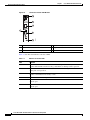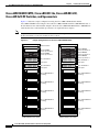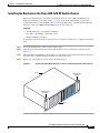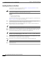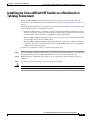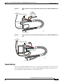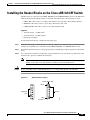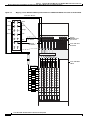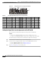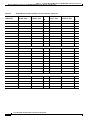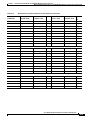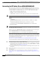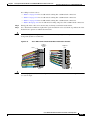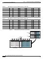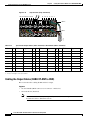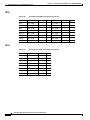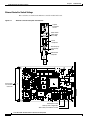
1
Cisco uBR-3x10 RF Switch Hardware
Installation and Cabling Guide
June 6, 2008
Americas Headquarters
Cisco Systems, Inc.
170 West Tasman Drive
San Jose, CA 95134-1706
USA
http://www.cisco.com
Tel: 408 526-4000
800 553-NETS (6387)
Fax: 408 527-0883
Text Part Number: OL-1984-06
THE SPECIFICATIONS AND INFORMATION REGARDING THE PRODUCTS IN THIS MANUAL ARE SUBJECT TO CHANGE WITHOUT NOTICE. ALL
STATEMENTS, INFORMATION, AND RECOMMENDATIONS IN THIS MANUAL ARE BELIEVED TO BE ACCURATE BUT ARE PRESENTED WITHOUT
WARRANTY OF ANY KIND, EXPRESS OR IMPLIED. USERS MUST TAKE FULL RESPONSIBILITY FOR THEIR APPLICATION OF ANY PRODUCTS.
THE SOFTWARE LICENSE AND LIMITED WARRANTY FOR THE ACCOMPANYING PRODUCT ARE SET FORTH IN THE INFORMATION PACKET THAT
SHIPPED WITH THE PRODUCT AND ARE INCORPORATED HEREIN BY THIS REFERENCE. IF YOU ARE UNABLE TO LOCATE THE SOFTWARE LICENSE
OR LIMITED WARRANTY, CONTACT YOUR CISCO REPRESENTATIVE FOR A COPY.
The following information is for FCC compliance of Class A devices: This equipment has been tested and found to comply with the limits for a Class A digital device, pursuant
to part 15 of the FCC rules. These limits are designed to provide reasonable protection against harmful interference when the equipment is operated in a commercial
environment. This equipment generates, uses, and can radiate radio-frequency energy and, if not installed and used in accordance with the instruction manual, may cause
harmful interference to radio communications. Operation of this equipment in a residential area is likely to cause harmful interference, in which case users will be required
to correct the interference at their own expense.
The following information is for FCC compliance of Class B devices: The equipment described in this manual generates and may radiate radio-frequency energy. If it is not
installed in accordance with Cisco’s installation instructions, it may cause interference with radio and television reception. This equipment has been tested and found to
comply with the limits for a Class B digital device in accordance with the specifications in part 15 of the FCC rules. These specifications are designed to provide reasonable
protection against such interference in a residential installation. However, there is no guarantee that interference will not occur in a particular installation.
Modifying the equipment without Cisco’s written authorization may result in the equipment no longer complying with FCC requirements for Class A or Class B digital
devices. In that event, your right to use the equipment may be limited by FCC regulations, and you may be required to correct any interference to radio or television
communications at your own expense.
You can determine whether your equipment is causing interference by turning it off. If the interference stops, it was probably caused by the Cisco equipment or one of its
peripheral devices. If the equipment causes interference to radio or television reception, try to correct the interference by using one or more of the following measures:
• Turn the television or radio antenna until the interference stops.
• Move the equipment to one side or the other of the television or radio.
• Move the equipment farther away from the television or radio.
• Plug the equipment into an outlet that is on a different circuit from the television or radio. (That is, make certain the equipment and the television or radio are on circuits
controlled by different circuit breakers or fuses.)
Modifications to this product not authorized by Cisco Systems, Inc. could void the FCC approval and negate your authority to operate the product.
The Cisco implementation of TCP header compression is an adaptation of a program developed by the University of California, Berkeley (UCB) as part of UCB’s public
domain version of the UNIX operating system. All rights reserved. Copyright © 1981, Regents of the University of California.
NOTWITHSTANDING ANY OTHER WARRANTY HEREIN, ALL DOCUMENT FILES AND SOFTWARE OF THESE SUPPLIERS ARE PROVIDED “AS IS” WITH
ALL FAULTS. CISCO AND THE ABOVE-NAMED SUPPLIERS DISCLAIM ALL WARRANTIES, EXPRESSED OR IMPLIED, INCLUDING, WITHOUT
LIMITATION, THOSE OF MERCHANTABILITY, FITNESS FOR A PARTICULAR PURPOSE AND NONINFRINGEMENT OR ARISING FROM A COURSE OF
DEALING, USAGE, OR TRADE PRACTICE.
IN NO EVENT SHALL CISCO OR ITS SUPPLIERS BE LIABLE FOR ANY INDIRECT, SPECIAL, CONSEQUENTIAL, OR INCIDENTAL DAMAGES, INCLUDING,
WITHOUT LIMITATION, LOST PROFITS OR LOSS OR DAMAGE TO DATA ARISING OUT OF THE USE OR INABILITY TO USE THIS MANUAL, EVEN IF CISCO
OR ITS SUPPLIERS HAVE BEEN ADVISED OF THE POSSIBILITY OF SUCH DAMAGES.
CCSP, the Cisco Square Bridge logo, Follow Me Browsing, and StackWise are trademarks of Cisco Systems, Inc.; Changing the Way We Work, Live, Play, and Learn, and iQuick
Study are service marks of Cisco Systems, Inc.; and Access Registrar, Aironet, ASIST, BPX, Catalyst, CCDA, CCDP, CCIE, CCIP, CCNA, CCNP, Cisco, the Cisco Certified
Internetwork Expert logo, Cisco IOS, Cisco Press, Cisco Systems, Cisco Systems Capital, the Cisco Systems logo, Cisco Unity, Empowering the Internet Generation,
Enterprise/Solver, EtherChannel, EtherFast, EtherSwitch, Fast Step, FormShare, GigaDrive, GigaStack, HomeLink, Internet Quotient, IOS, IP/TV, iQ Expertise, the iQ logo, iQ
Net Readiness Scorecard, LightStream, Linksys, MeetingPlace, MGX, the Networkers logo, Networking Academy, Network Registrar, Packet, PIX, Post-Routing, Pre-Routing,
ProConnect, RateMUX, ScriptShare, SlideCast, SMARTnet, StrataView Plus, SwitchProbe, TeleRouter, The Fastest Way to Increase Your Internet Quotient, TransPath, and VCO
are registered trademarks of Cisco Systems, Inc. and/or its affiliates in the United States and certain other countries.
All other trademarks mentioned in this document or Website are the property of their respective owners. The use of the word partner does not imply a partnership relationship
between Cisco and any other company. (0501R)
Cisco uBR-3x10 RF Switch Hardware Installation and Cabling Guide
Copyright © 2004–2007 Cisco Systems, Inc. All rights reserved.
Preface
This preface describes the objectives, intended audience, and organization of this document and explains
how to find additional information on related products and services. This preface contains the following
sections:
•
Document Objectives, page 3
•
Audience, page 3
•
Scope, page 4
•
Document Organization, page 4
•
Document Conventions, page 4
•
Related Documentation, page 10
•
Obtaining Documentation, page 11
•
Documentation Feedback, page 12
•
Obtaining Technical Assistance, page 12
•
Obtaining Additional Publications and Information, page 13
Document Objectives
Use this document as a guide when installing and cabling the Cisco uBR 3x10 RF Switch at the cable
headend or distribution hub.
Audience
This guide is intended for cable system installers and technicians who physically install and connect the
Cisco uBR 3x10 RF Switch and associated equipment at the cable headend or distribution hub. Cable
system installers and technicians should be familiar with their cable plant's base operating parameters
and service offerings.
Warning
Only trained and qualified personnel should be allowed to install, replace, or service this equipment.
Statement 1030
Cisco uBR-3x10 RF Switch Hardware Installation and Cabling Guide
OL-1984-06
3
Preface
Scope
Tip
Statement numbers (Statement 1030) at the end of a warning refer to specific warnings and their
translations found in the Regulatory Compliance and Safety Information for the Cisco RF Switch.
Scope
The guide provides installation and cabling information for the Cisco uBR 3x10 RF Switch. Refer to the
“Related Documentation” section on page 10 for related Cisco publications that provide configuration
information for the Cisco uBR 3x10 RF Switch.
Document Organization
This hardware installation guide is organized into the following chapters and appendixes:
Chapter Title
Description
Chapter 1, “Cisco uBR-3x10 RF
Switch Overview”
Describes the Cisco uBR 3x10 RF Switch chassis and
components, illustrating the supported system configurations.
Chapter 2, “Preparing for
Installation”
Describes safety considerations, tools, and other equipment
required to prepare your site.
Chapter 3, “Installing the
Cisco RF Switch”
Provides instructions to install and connect cables to the chassis.
Chapter 4, “Cabling the RF Switch Provides instructions for connecting Cisco uBR 3x10 RF Switch
With the Cisco uBR10012 CMTS cable network redundancy cables in a Cisco uBR10012 CMTS
environment.
Cable Interface Line Cards”
Chapter 6, “Troubleshooting”
Provides basic Cisco uBR 3x10 RF Switch troubleshooting
information.
Appendix A, “Specifications and
Component Part Numbers”
Provides Cisco uBR 3x10 RF Switch system specifications.
Document Conventions
This guide uses the following conventions:
Note
Caution
Means reader take note. Notes contain helpful suggestions or references to materials not contained in
this manual.
Means reader be careful. You are capable of doing something that might result in equipment damage or
loss of data.
Cisco uBR-3x10 RF Switch Hardware Installation and Cabling Guide
4
OL-1984-06
Preface
Document Conventions
Tip
Means the following information might help you solve a problem.
Warning Definition
Warning
IMPORTANT SAFETY INSTRUCTIONS
This warning symbol means danger. You are in a situation that could cause bodily injury. Before you
work on any equipment, be aware of the hazards involved with electrical circuitry and be familiar
with standard practices for preventing accidents. Use the statement number provided at the end of
each warning to locate its translation in the translated safety warnings that accompanied this
device. Statement 1071
SAVE THESE INSTRUCTIONS
Waarschuwing
BELANGRIJKE VEILIGHEIDSINSTRUCTIES
Dit waarschuwingssymbool betekent gevaar. U verkeert in een situatie die lichamelijk letsel kan
veroorzaken. Voordat u aan enige apparatuur gaat werken, dient u zich bewust te zijn van de bij
elektrische schakelingen betrokken risico's en dient u op de hoogte te zijn van de standaard
praktijken om ongelukken te voorkomen. Gebruik het nummer van de verklaring onderaan de
waarschuwing als u een vertaling van de waarschuwing die bij het apparaat wordt geleverd, wilt
raadplegen.
BEWAAR DEZE INSTRUCTIES
Varoitus
TÄRKEITÄ TURVALLISUUSOHJEITA
Tämä varoitusmerkki merkitsee vaaraa. Tilanne voi aiheuttaa ruumiillisia vammoja. Ennen kuin
käsittelet laitteistoa, huomioi sähköpiirien käsittelemiseen liittyvät riskit ja tutustu
onnettomuuksien yleisiin ehkäisytapoihin. Turvallisuusvaroitusten käännökset löytyvät laitteen
mukana toimitettujen käännettyjen turvallisuusvaroitusten joukosta varoitusten lopussa näkyvien
lausuntonumeroiden avulla.
SÄILYTÄ NÄMÄ OHJEET
Attention
IMPORTANTES INFORMATIONS DE SÉCURITÉ
Ce symbole d'avertissement indique un danger. Vous vous trouvez dans une situation pouvant
entraîner des blessures ou des dommages corporels. Avant de travailler sur un équipement, soyez
conscient des dangers liés aux circuits électriques et familiarisez-vous avec les procédures
couramment utilisées pour éviter les accidents. Pour prendre connaissance des traductions des
avertissements figurant dans les consignes de sécurité traduites qui accompagnent cet appareil,
référez-vous au numéro de l'instruction situé à la fin de chaque avertissement.
CONSERVEZ CES INFORMATIONS
Cisco uBR-3x10 RF Switch Hardware Installation and Cabling Guide
OL-1984-06
5
Preface
Document Conventions
Warnung
WICHTIGE SICHERHEITSHINWEISE
Dieses Warnsymbol bedeutet Gefahr. Sie befinden sich in einer Situation, die zu Verletzungen führen
kann. Machen Sie sich vor der Arbeit mit Geräten mit den Gefahren elektrischer Schaltungen und
den üblichen Verfahren zur Vorbeugung vor Unfällen vertraut. Suchen Sie mit der am Ende jeder
Warnung angegebenen Anweisungsnummer nach der jeweiligen Übersetzung in den übersetzten
Sicherheitshinweisen, die zusammen mit diesem Gerät ausgeliefert wurden.
BEWAHREN SIE DIESE HINWEISE GUT AUF.
Avvertenza
IMPORTANTI ISTRUZIONI SULLA SICUREZZA
Questo simbolo di avvertenza indica un pericolo. La situazione potrebbe causare infortuni alle
persone. Prima di intervenire su qualsiasi apparecchiatura, occorre essere al corrente dei pericoli
relativi ai circuiti elettrici e conoscere le procedure standard per la prevenzione di incidenti.
Utilizzare il numero di istruzione presente alla fine di ciascuna avvertenza per individuare le
traduzioni delle avvertenze riportate in questo documento.
CONSERVARE QUESTE ISTRUZIONI
Advarsel
VIKTIGE SIKKERHETSINSTRUKSJONER
Dette advarselssymbolet betyr fare. Du er i en situasjon som kan føre til skade på person. Før du
begynner å arbeide med noe av utstyret, må du være oppmerksom på farene forbundet med
elektriske kretser, og kjenne til standardprosedyrer for å forhindre ulykker. Bruk nummeret i slutten
av hver advarsel for å finne oversettelsen i de oversatte sikkerhetsadvarslene som fulgte med denne
enheten.
TA VARE PÅ DISSE INSTRUKSJONENE
Aviso
INSTRUÇÕES IMPORTANTES DE SEGURANÇA
Este símbolo de aviso significa perigo. Você está em uma situação que poderá ser causadora de
lesões corporais. Antes de iniciar a utilização de qualquer equipamento, tenha conhecimento dos
perigos envolvidos no manuseio de circuitos elétricos e familiarize-se com as práticas habituais de
prevenção de acidentes. Utilize o número da instrução fornecido ao final de cada aviso para
localizar sua tradução nos avisos de segurança traduzidos que acompanham este dispositivo.
GUARDE ESTAS INSTRUÇÕES
¡Advertencia!
INSTRUCCIONES IMPORTANTES DE SEGURIDAD
Este símbolo de aviso indica peligro. Existe riesgo para su integridad física. Antes de manipular
cualquier equipo, considere los riesgos de la corriente eléctrica y familiarícese con los
procedimientos estándar de prevención de accidentes. Al final de cada advertencia encontrará el
número que le ayudará a encontrar el texto traducido en el apartado de traducciones que acompaña
a este dispositivo.
GUARDE ESTAS INSTRUCCIONES
Cisco uBR-3x10 RF Switch Hardware Installation and Cabling Guide
6
OL-1984-06
Preface
Document Conventions
Varning!
VIKTIGA SÄKERHETSANVISNINGAR
Denna varningssignal signalerar fara. Du befinner dig i en situation som kan leda till personskada.
Innan du utför arbete på någon utrustning måste du vara medveten om farorna med elkretsar och
känna till vanliga förfaranden för att förebygga olyckor. Använd det nummer som finns i slutet av
varje varning för att hitta dess översättning i de översatta säkerhetsvarningar som medföljer denna
anordning.
SPARA DESSA ANVISNINGAR
Cisco uBR-3x10 RF Switch Hardware Installation and Cabling Guide
OL-1984-06
7
Preface
Document Conventions
Aviso
INSTRUÇÕES IMPORTANTES DE SEGURANÇA
Este símbolo de aviso significa perigo. Você se encontra em uma situação em que há risco de lesões
corporais. Antes de trabalhar com qualquer equipamento, esteja ciente dos riscos que envolvem os
circuitos elétricos e familiarize-se com as práticas padrão de prevenção de acidentes. Use o
número da declaração fornecido ao final de cada aviso para localizar sua tradução nos avisos de
segurança traduzidos que acompanham o dispositivo.
GUARDE ESTAS INSTRUÇÕES
Advarsel
VIGTIGE SIKKERHEDSANVISNINGER
Dette advarselssymbol betyder fare. Du befinder dig i en situation med risiko for
legemesbeskadigelse. Før du begynder arbejde på udstyr, skal du være opmærksom på de
involverede risici, der er ved elektriske kredsløb, og du skal sætte dig ind i standardprocedurer til
undgåelse af ulykker. Brug erklæringsnummeret efter hver advarsel for at finde oversættelsen i de
oversatte advarsler, der fulgte med denne enhed.
GEM DISSE ANVISNINGER
Cisco uBR-3x10 RF Switch Hardware Installation and Cabling Guide
8
OL-1984-06
Preface
Document Conventions
Cisco uBR-3x10 RF Switch Hardware Installation and Cabling Guide
OL-1984-06
9
Preface
Related Documentation
Related Documentation
For high availablity (HA) information, see:
•
N+1 Redundancy Using the Cisco RF Switch at the following URL:
http://www.cisco.com/en/US/partner/tech/tk86/tk804/technologies_tech_note09186a0080204374.s
html
•
N+1 Solution for the uBR10012 at the following url:
http://www.cisco.com/en/US/partner/products/hw/cable/ps2209/products_tech_note09186a00801f
7638.shtml
•
N+1 Solution for the uBR7200 with MC28C or MC16x Cards at the following URL:
http://www.cisco.com/en/US/customer/tech/tk86/tk804/technologies_tech_note09186a008020
5618.shtml
•
N+1 Redundancy using the Vecima HD4040 Upconverter at the following URL:
http://www.cisco.com/en/US/customer/tech/tk86/tk804/technologies_tech_note09186a00801f76
22.shtml
•
N+1 Feature Updates (N+1/5x20 and N+1/CLI sync) at the following URLs:
http://www.cisco.com/univercd/cc/td/doc/product/cable/cab_rout/cmtsfg/index.htm
http://www.cisco.com/en/US/products/hw/cable/ps2217/products_configuration_guide_chapter
09186a008015096c.html
•
“N+1 Redundancy for the Cisco CMTS" chapter of the Cisco Cable Modem Termination System
Feature Guide, at the following URL:
http://www.cisco.com/en/US/products/hw/cable/ps2217/products_feature_guide09186a0080150
96c.html
For installation information, see:
•
Rack-Mounting the Cisco RF Switch with the Cisco uBR10012 CMTS, at the following URL:
http://www.cisco.com/univercd/cc/td/doc/product/cable/rfswitch/index.htm
•
Rack-Mounting the Cisco RF Switch with the Cisco uBR7246VXR CMTS, at the following URL:
http://www.cisco.com/univercd/cc/td/doc/product/cable/rfswitch/index.htm
Cisco uBR-3x10 RF Switch Hardware Installation and Cabling Guide
10
OL-1984-06
Preface
Obtaining Documentation
•
Cabling the Cisco uBR 3x10 RF Switch, at the following URL:
http://www.cisco.com/univercd/cc/td/doc/product/cable/rfswitch/index.htm
•
Vecima HD4040 series IF-to-RF upconverter, at the following URL:
http://www.vecima.com
For other information, see:
•
Cisco uBR 3x10 Switch Documentation Roadmap, at the following URL:
http://www.cisco.com/univercd/cc/td/doc/product/cable/rfswitch/rdmp310.htm
•
Regulatory Compliance and Safety Information for the Cisco RF Switch, at the following URL:
http://www.cisco.com/univercd/cc/td/doc/product/cable/rfswitch/rfs_rcsi.htm
•
Warranty information, at the following URL:
http://www.cisco.com/univercd/cc/td/doc/es_inpck/cetrans.htm
Obtaining Documentation
Cisco documentation and additional literature are available on Cisco.com. Cisco also provides several
ways to obtain technical assistance and other technical resources. These sections explain how to obtain
technical information from Cisco Systems.
Cisco.com
You can access the most current Cisco documentation at this URL:
http://www.cisco.com/univercd/home/home.htm
You can access the Cisco website at this URL:
http://www.cisco.com
You can access international Cisco websites at this URL:
http://www.cisco.com/public/countries_languages.shtml
Ordering Documentation
You can find instructions for ordering documentation at this URL:
http://www.cisco.com/univercd/cc/td/doc/es_inpck/pdi.htm
You can order Cisco documentation in these ways:
•
Registered Cisco.com users (Cisco direct customers) can order Cisco product documentation from
the Ordering tool:
http://www.cisco.com/en/US/partner/ordering/index.shtml
•
Nonregistered Cisco.com users can order documentation through a local account representative by
calling Cisco Systems Corporate Headquarters (California, USA) at 408 526-7208 or, elsewhere in
North America, by calling 800 553-NETS (6387).
Cisco uBR-3x10 RF Switch Hardware Installation and Cabling Guide
OL-1984-06
11
Preface
Documentation Feedback
Documentation Feedback
You can send comments about technical documentation to [email protected].
You can submit comments by using the response card (if present) behind the front cover of your
document or by writing to the following address:
Cisco Systems
Attn: Customer Document Ordering
170 West Tasman Drive
San Jose, CA 95134-9883
We appreciate your comments.
Obtaining Technical Assistance
For all customers, partners, resellers, and distributors who hold valid Cisco service contracts, Cisco
Technical Support provides 24-hour-a-day, award-winning technical assistance. The Cisco Technical
Support Website on Cisco.com features extensive online support resources. In addition, Cisco Technical
Assistance Center (TAC) engineers provide telephone support. If you do not hold a valid Cisco service
contract, contact your reseller.
Cisco Technical Support Website
The Cisco Technical Support Website provides online documents and tools for troubleshooting and
resolving technical issues with Cisco products and technologies. The website is available 24 hours a day,
365 days a year at this URL:
http://www.cisco.com/techsupport
Access to all tools on the Cisco Technical Support Website requires a Cisco.com user ID and password.
If you have a valid service contract but do not have a user ID or password, you can register at this URL:
http://tools.cisco.com/RPF/register/register.do
Submitting a Service Request
Using the online TAC Service Request Tool is the fastest way to open S3 and S4 service requests. (S3
and S4 service requests are those in which your network is minimally impaired or for which you require
product information.) After you describe your situation, the TAC Service Request Tool automatically
provides recommended solutions. If your issue is not resolved using the recommended resources, your
service request will be assigned to a Cisco TAC engineer. The TAC Service Request Tool is located at
this URL:
http://www.cisco.com/techsupport/servicerequest
For S1 or S2 service requests or if you do not have Internet access, contact the Cisco TAC by telephone.
(S1 or S2 service requests are those in which your production network is down or severely degraded.)
Cisco TAC engineers are assigned immediately to S1 and S2 service requests to help keep your business
operations running smoothly.
Cisco uBR-3x10 RF Switch Hardware Installation and Cabling Guide
12
OL-1984-06
Preface
Obtaining Additional Publications and Information
To open a service request by telephone, use one of the following numbers:
Asia-Pacific: +61 2 8446 7411 (Australia: 1 800 805 227)
EMEA: +32 2 704 55 55
USA: 1 800 553 2447
For a complete list of Cisco TAC contacts, go to this URL:
http://www.cisco.com/techsupport/contacts
Definitions of Service Request Severity
To ensure that all service requests are reported in a standard format, Cisco has established severity
definitions.
Severity 1 (S1)—Your network is “down,” or there is a critical impact to your business operations. You
and Cisco will commit all necessary resources around the clock to resolve the situation.
Severity 2 (S2)—Operation of an existing network is severely degraded, or significant aspects of your
business operation are negatively affected by inadequate performance of Cisco products. You and Cisco
will commit full-time resources during normal business hours to resolve the situation.
Severity 3 (S3)—Operational performance of your network is impaired, but most business operations
remain functional. You and Cisco will commit resources during normal business hours to restore service
to satisfactory levels.
Severity 4 (S4)—You require information or assistance with Cisco product capabilities, installation, or
configuration. There is little or no effect on your business operations.
Obtaining Additional Publications and Information
Information about Cisco products, technologies, and network solutions is available from various online
and printed sources.
•
Cisco Marketplace provides a variety of Cisco books, reference guides, and logo merchandise. Visit
Cisco Marketplace, the company store, at this URL:
http://www.cisco.com/go/marketplace/
•
The Cisco Product Catalog describes the networking products offered by Cisco Systems, as well as
ordering and customer support services. Access the Cisco Product Catalog at this URL:
http://cisco.com/univercd/cc/td/doc/pcat/
•
Cisco Press publishes a wide range of general networking, training and certification titles. Both new
and experienced users will benefit from these publications. For current Cisco Press titles and other
information, go to Cisco Press at this URL:
http://www.ciscopress.com
•
Packet magazine is the Cisco Systems technical user magazine for maximizing Internet and
networking investments. Each quarter, Packet delivers coverage of the latest industry trends,
technology breakthroughs, and Cisco products and solutions, as well as network deployment and
troubleshooting tips, configuration examples, customer case studies, certification and training
information, and links to scores of in-depth online resources. You can access Packet magazine at this
URL:
http://www.cisco.com/packet
Cisco uBR-3x10 RF Switch Hardware Installation and Cabling Guide
OL-1984-06
13
Preface
Obtaining Additional Publications and Information
•
iQ Magazine is the quarterly publication from Cisco Systems designed to help growing companies
learn how they can use technology to increase revenue, streamline their business, and expand
services. The publication identifies the challenges facing these companies and the technologies to
help solve them, using real-world case studies and business strategies to help readers make sound
technology investment decisions. You can access iQ Magazine at this URL:
http://www.cisco.com/go/iqmagazine
•
Internet Protocol Journal is a quarterly journal published by Cisco Systems for engineering
professionals involved in designing, developing, and operating public and private internets and
intranets. You can access the Internet Protocol Journal at this URL:
http://www.cisco.com/ipj
•
World-class networking training is available from Cisco. You can view current offerings at
this URL:
http://www.cisco.com/en/US/learning/index.html
Cisco uBR-3x10 RF Switch Hardware Installation and Cabling Guide
14
OL-1984-06
CH A P T E R
1
Cisco uBR-3x10 RF Switch Overview
This chapter describes the Cisco uBR 3x10 RF Switch. The chapter contains the following sections:
•
About the Cisco uBR 3x10 RF Switch, page 1-1
•
Hardware Component Descriptions, page 1-4
•
Cable Kits, page 1-10
About the Cisco uBR 3x10 RF Switch
The Cisco uBR 3x10 RF Switch is designed to work with the Cisco uBR10012 CMTS or the
Cisco uBR7246VXR CMTS in a cable headend or hub to provide N+1 redundancy for applications such
as Voice over IP (VoIP).
The Cisco uBR 3x10 RF Switch is a rack-mount unit that contains the RF combiners and splitters,
RF switches, and switch drivers. The RF switch uses Cisco RF Switch logic, and a Simple Network
Management Protocol (SNMP) control interface. The Cisco uBR 3x10 RF Switch can be controlled
using SNMP from the Cisco uBR10012 CMTS or the Cisco uBR7246VXR CMTS.
Chassis Features
The Cisco uBR 3x10 RF Switch chassis features:
•
One power-supply module that provides either 100 to 240 VAC or –48 to –60 VDC power to the
Cisco uBR 3x10 RF Switch chassis.
•
One Ethernet controller module that provides SNMP control for automatic redundancy channel
selection.
•
Ten upstream (low-frequency) switch modules that provide 75-ohm termination and automatic
upstream redundancy switching from 5 to 70 MHz.
•
Three downstream (high-frequency) switch modules that provide 75-ohm termination and automatic
downstream redundancy switching from 54 to 860 MHz.
•
Eight power divider assemblies used to route signals to and from the appropriate upstream or
downstream assemblies or protect interfaces.
•
One midplane assembly that distributes power and control signals from the power supply and
Ethernet controller to the upstream and downstream switch assemblies.
Cisco uBR-3x10 RF Switch Hardware Installation and Cabling Guide
OL-1984-06
1-1
Chapter 1
Cisco uBR-3x10 RF Switch Overview
About the Cisco uBR 3x10 RF Switch
Other chassis features include:
•
Front panel serviceability—for no downtime on RF interfaces. All active modules can be replaced
from the front panel.
•
10BASE-T Ethernet interface over which you can control the configuration and operation of the
Cisco uBR 3x10 RF Switch by means of SNMP from a Cisco universal broadband router.
•
Upstream and downstream assembly online insertion and removal (OIR) or “hot swapping”
capability.
•
CLEI codes for all replaceable modules.
•
Rack-mountable—Each unit can be rack-mounted into any rack or cabinet that is designed per
EIA-310 or MIL-STD-189 using the supplied rack-mount brackets.
The Ethernet controller, power supply, upstream modules, and downstream modules are accessed from
the front of the chassis. (See Figure 1-1.)
Figure 1-1
Front View of the Cisco uBR-3x10 RF Switch
7
1
6
2
5
103285
4
3
Note
1
Ground lug installation location
5
Downstream switch modules (3)
2
Power supply
6
Mounting brackets
3
Ethernet controller module
7
Upstream switch modules (10)
4
Blank slot
Figure 1-1shows the mounting brackets located at the front of the chassis. The brackets can also be
mounted at the rear of the chassis.
The CMTS, PROTECT, and CABLE PLANT MCX connections are accessed from the rear of the
RF switch chassis. (see Figure 1-2.)
Cisco uBR-3x10 RF Switch Hardware Installation and Cabling Guide
1-2
OL-1984-06
Chapter 1
Cisco uBR-3x10 RF Switch Overview
About the Cisco uBR 3x10 RF Switch
Figure 1-2
Rear View of the Cisco uBR-3x10 RF Switch
103286
1
2
3
4
1
Mounting brackets
3
PROTECT MCX connector location
2
CMTS (working) MCX connector location
4
CABLE PLANT MCX connector location
Interface Overview
The following sections describe interface numbering, and MAC address assignments.
Interface Numbering
In all of the Cisco RF switches, the slot number is the chassis slot in which an Ethernet controller or an
upstream switch module or downstream switch module is installed, and the logical interface number is
the physical location of the interface port on an Ethernet controller.
The MAC-layer or hardware address is a standardized data link layer address that is required for certain
network interface types. The Cisco uBR 3x10 RF Switch uses a specific method to assign and control
the MAC-layer addresses of its Ethernet controller.
The Ethernet controller and upstream and downstream module slots keep the same slot number
regardless of whether other Ethernet controllers or upstream or downstream modules are installed or
removed. However, when you move an upstream or downstream module to a different slot, the logical
interface number changes to reflect the new slot number. The Ethernet card is always installed in the
same slot.
For complete descriptions and instructions for the commands used to configure your Cisco RF switch,
refer to the “N+1 Redundancy for the Cisco CMTS” chapter of the Cisco CMTS Feature Guide, which
is available on Cisco.com. (See the “Obtaining Documentation” section on page 11.)
MAC-Layer Address Assignments
All LAN interfaces (ports) require unique MAC-layer addresses, also known as hardware addresses.
Typically, the MAC address of an interface is stored on a memory component that resides directly on the
interface circuitry; however, the online insertion and removal (OIR) feature requires a different method.
Cisco uBR-3x10 RF Switch Hardware Installation and Cabling Guide
OL-1984-06
1-3
Chapter 1
Cisco uBR-3x10 RF Switch Overview
Hardware Component Descriptions
OIR Feature
The OIR feature allows you to remove an Ethernet controller or an upstream or downstream module and
replace it with another identically configured one. If the new controller or module matches the controller
or module you removed, the system immediately brings it online. To allow OIR, an address allocator
with a unique MAC address is stored in an EEPROM on the Cisco RF switch midplane. Each address is
reserved for a specific port and slot in the switch, regardless of whether an Ethernet controller or an
upstream or downstream switch module resides in that slot.
Slot MAC Addresses
The MAC addresses are assigned to the slots in sequence. The first address is assigned to Ethernet
controller slot 0, and the next addresses are assigned to upstream and downstream card slots 1 through
14 (refer to the “Cisco uBR 3x10 RF Switch Slot Information” section on page 6-7 for slot location
information). This address scheme allows you to remove the Ethernet controllers or upstream and
downstream cards and insert them into other switches without causing the MAC addresses to move
around the network or be assigned to multiple devices.
Hardware Component Descriptions
The following components are included in the Cisco uBR 3x10 RF Switch chassis:
•
Power supply module
•
Ethernet controller module
•
Upstream (low-frequency) switch modules
•
Downstream (high-frequency) switch modules
Power Supply Module
•
Cisco part number 74-2624-01 (see Figure 1-3 on page 1-5).
The power supply module takes 100 to 240 VAC input and provides +12 VDC output. It also takes
-40.5 to -72 VDC input and supplies +12 VDC output.
A control switch on the front panel is used to select DC input or AC input operation. This a 20-W power
supply.
Caution
When inserting or removing the power supply from the Cisco uBR 3x10 RF Switch chassis, you must
use a screwdriver to tighten and loosen the captive installation screws.
Cisco uBR-3x10 RF Switch Hardware Installation and Cabling Guide
1-4
OL-1984-06
Chapter 1
Cisco uBR-3x10 RF Switch Overview
Hardware Component Descriptions
Figure 1-3
Power Supply Module
2
1
3
4
5
95644
6
1
Strain relief for DC power cables
2
Captive screws
3
Power LED (green–on)
4
DC power connection
5
Power select switch (power off, AC, or DC).
This is a three way toggle switch, the center
position is off; toggle down for AC, toggle up
for DC.
6
AC power input with strain relief retainer clip
Ethernet Controller Module
•
Cisco part number 74-2620-01 (see Figure 1-4 on page 1-6).
Within the Cisco uBR 3x10 RF Switch system, only one Ethernet controller is used.
The Ethernet controller module performs two primary functions.
•
Connecting the Cisco uBR 3x10 RF Switch to a Cisco uBR10012 router or a Cisco uBR7246VXR
router. You can use a crossover cable to connect the Cisco CMTS to the RF switch Ethernet
controller’s RJ-45 receptacle. Or, you can use a straight-through cable to connect the RF switch and
the CMTS through an ethernet switch or a hub. This connection allows you to remotely control both
automatic and manual operations of the Cisco RF switch by passing SNMP traffic between the
Cisco RF switch and the Cisco CMTS.
For example, when a cable interface line card on the Cisco universal broadband router experiences
a failure or if the Cisco universal broadband router detects a large number of remote customer
premises equipment (CPE) devices that have gone offline, an SNMP alert is automatically
transmitted to the Cisco uBR 3x10 RF Switch and a protecting cable interface line card assumes
working status for the failed or faulty cable interface line card.
•
Connecting a console terminal to the Cisco uBR 3x10 RF Switch. You can use a rollover cable to
connect the console terminal to the RF switch Ethernet controller’s EIA/TIA-232 receptacle.This
connection allows you to configure the Cisco uBR 3x10 RF Switch for N+1 redundancy. Use the
configuration commands described in the “N+1 Redundancy for the Cisco CMTS” chapter of the
Cisco CMTS Feature Guide, available on Cisco.com. (See the “Obtaining Documentation” section
on page 11.)
Cisco uBR-3x10 RF Switch Hardware Installation and Cabling Guide
OL-1984-06
1-5
Chapter 1
Cisco uBR-3x10 RF Switch Overview
Hardware Component Descriptions
Figure 1-4
Ethernet Controller PCB Module
5
4
3
1
5
95645
2
1
Transmit (TX) and receive (RX) LEDs
4
Status LEDs (SYS, ERR, ACT, LNK)
2
EAI/TIA–232 connection
5
Captive screws
3
RJ–45 connection
Table 1-1 describes the Ethernet controller’s LEDs.
Table 1-1
Ethernet Controller LEDs
LED
Function
SYS
Indicates that the Ethernet controller is enabled for operation in the system. This LED
flashes while the RF switch is booting, and remains on during normal operation.
ERR
Indicates that a serious error has occurred either while booting the RF switch, or
during line card operation.
ACT
Indicates that there is activity over the 10BASE-T Ethernet RJ-45 interface. This LED
flashes as transmit/receive activity occurs.
LNK
Indicates that the Ethernet port has established a valid link with the network.
TX
This LED flashes as the Ethernet controller transmits data via the EIA/TIA-232
console port.
RX
This LED flashes as the Ethernet controller receives data via the EIA/TIA-232
console port.
Cisco uBR-3x10 RF Switch Hardware Installation and Cabling Guide
1-6
OL-1984-06
Chapter 1
Cisco uBR-3x10 RF Switch Overview
Hardware Component Descriptions
Upstream Switch Modules
•
Cisco part number 74-2622-01 (See Figure 1-5.)
There are 10 upstream switch modules used in the Cisco uBR 3x10 RF Switch. The module operates
over the from 5 to 70 MHz. Each module has ten 75-ohm inputs accessed through the MCX connectors
on the backpanel of the RF switch (see Figure 1-2 on page 1-3). During normal system operation, all of
the upstream switches direct traffic to their respective default termination interfaces.
Note
Upstream cables from the cable interface line cards are plugged into the CMTS MCX connections in the
rear of the Cisco uBR 3x10 RF Switch. See Chapter 4, “Cabling the RF Switch With the Cisco
uBR10012 CMTS Cable Interface Line Cards,” for more information about cabling the RF switch.
The upstream switch module takes the signal inputs (eight) from the power splitter and routes one of the
eight to a protect output, or splits the inputs into two groups of four and sets up the switches to select
one input (of a group of four) as a protect output. The relays are electromechanical, latching relays that
are controlled through an I2C interface. The switch card provides a minimum of 60 dB of isolation from
connector port to connector port during normal operation and more than 20 dB when operating in protect
mode.
Upstream Switch Card
103288
Figure 1-5
Captive screw
Captive screw
Each upstream switch has a set of four LEDs that indicate the working status of the port as described in
Table 1-2.
Table 1-2
Upstream Switch Board LED Descriptions
LED Name
Color
Description
Protect 1
Green/Yellow
Indicates CMTS/PROTECT 1
Protect 2
Green/ Yellow
Indicates CABLE PLANT/PROTECT 2
Error 1
Off/Yellow
Indicates a channel problem 1
Error 2
Off/Yellow
Indicates a channel problem 2
Cisco uBR-3x10 RF Switch Hardware Installation and Cabling Guide
OL-1984-06
1-7
Chapter 1
Cisco uBR-3x10 RF Switch Overview
Hardware Component Descriptions
Downstream Switch Module
•
Cisco part number 74-2623-01 (See Figure 1-6 on page 1-8)
Three downstream (high-frequency) switch modules are used in the Cisco uBR 3x10 RF Switch. The
module operates from 54 to 860 MHz. Each downstream switch module has ten 75-ohm inputs accessed
through the CABLE PLANT MCX connectors on the backpanel of the RF switch. During normal system
operation, the downstream switch module switches all direct traffic to their respective default
termination interfaces.
Note
See Chapter 4, “Cabling the RF Switch With the Cisco uBR10012 CMTS Cable Interface Line Cards,”
for more cabling information.
The downstream switch module accepts signal inputs (eight) from the power combiner and combines one
of the eight to a protect output. Alternately, the switch splits the inputs into two groups of four and then
selects one input (in the group of four) to combine with the protect input. The relays are
electromechanical, latching relays that are controlled through an I2C interface. The switch card provides
a minimum of 60 dB of isolation from connector port to connector port.
Downstream Switch PCB Assembly
103287
Figure 1-6
Captive screw
Captive screw
Each downstream switch board contains a set of four LEDs that indicates the working status of the port
as described in Table 1-3 on page 1-8.
Table 1-3
Downstream Switch Board LED Descriptions
LED Name
Color
Description
Protect 1
Green/Yellow
Indicates CMTS/PROTECT 1
Protect 2
Green/ Yellow
Indicates CABLE PLANT/PROTECT 2
Error 1
Off/Yellow
Indicates a channel problem 1
Error 2
Off/Yellow
Indicates a channel problem 2
Cisco uBR-3x10 RF Switch Hardware Installation and Cabling Guide
1-8
OL-1984-06
Chapter 1
Cisco uBR-3x10 RF Switch Overview
Hardware Component Descriptions
Figure 1-7
RF Switch Module Schematic (Upstream and Downstream)
Protect
1 2
out
8
in
out
7
in
out
6
in
out
5
in
out
4
in
out
3
in
out
2
in
out
1
in
95901
Memory
and
drivers
Switch board
Power Divider Assembly
The power divider assembly contains 16 splitters that operate from 5 to 860 MHz. The board also
contains four protect feed-through connections. The power splitter provides a minimum of 60 dB of
isolation from connector port to connector port.
The power divider assemblies are connected directly to the upstream and downstream card assemblies
through an access area in the midplane card.
Note
This assembly is not a field-replaceable unit (FRU).
Midplane Assembly
The midplane assembly is located in the center of the chassis and connects the upstream and downstream
to the power supply and Ethernet card assemblies. This card distributes +12V power, ground, and the I2C
control signals to the 14 switch card positions available.
Note
This assembly is not a field-replaceable unit (FRU).
Cisco uBR-3x10 RF Switch Hardware Installation and Cabling Guide
OL-1984-06
1-9
Chapter 1
Cisco uBR-3x10 RF Switch Overview
Cable Kits
Cable Kits
The cables approved for use in the Cisco N+1 redundancy solution, are Mini Precision RG59 (95
percent) tinned copper braid with (100 percent) foil shield. This cable is serial digital interface (SDI)
rated with a 1 MHz to 3 GHz rating.
•
CAB-RFSW-3x10-T (bundled cable kit:1.2-m, CMTS to RFS, F to MCX). This kit includes 10
cables, 2 cables have F-connectors on both ends for UPx connections and 2 are single 0.2-m cables,
the others are 1.2-m F-connector to MCX-connector cables.
•
CAB-RFSW-3x10⁻¹⁰T (bunbled cable kit:10-m, RFS to HUB, MCX to F). This kit includes 10
cables, 2 single 10-m cables, and 13 extra F-connectors.
•
CAB-RFSW5X20TPMF (bundled cable kit, 3-m, MCX to F). This kit includes 2 bundles of 10
cables, 1 bundle of 5 cables, and 25 extra F-connectors.
•
CAB-RFS5X20TIMM (bundled cable kit, 1-m, MCX to MCX). This kit includes 2 bundles of 10
cables, 1 bundle of 5 cables, and 4 headers (2 extra to be used with the output cable kit,
CAB-RFSW-3x10⁻¹⁰T.
The different jacket colors are used for easy identification. The gray and brown RF cables are
preterminated with the F-connectors used to connect to the Vecima HD4040 series IF-to-RF upconverter
input.
Cisco uBR-3x10 RF Switch Hardware Installation and Cabling Guide
1-10
OL-1984-06
CH A P T E R
2
Preparing for Installation
This chapter describes the site requirements for installing the Cisco uBR 3x10 RF Switch. The chapter
contains the following sections:
•
Safety, page 2-2
•
Site Requirements, page 2-5
•
Provisioning the Headend, page 2-7
•
Tools for Installation, page 2-9
•
Verifying the Shipping Container Contents, page 2-11
Warning
Only trained and qualified personnel should be allowed to install, replace, or service this equipment.
Statement 1030
Warning
This unit is intended for installation in restricted access areas. A restricted access area can be
accessed only through the use of a special tool, lock and key, or other means of security.
Statement 1017
Warning
This equipment must be installed and maintained by service personnel as defined by AS/NZS 3260.
Incorrectly connecting this equipment to a general-purpose outlet could be hazardous. The
telecommunications lines must be disconnected 1) before unplugging the main power connector or 2)
while the housing is open, or both. Statement 1043
Warning
Ultimate disposal of this product should be handled according to all national laws and regulations.
Statement 1040
Cisco uBR-3x10 RF Switch Hardware Installation and Cabling Guide
OL-1984-06
2-1
Chapter 2
Preparing for Installation
Safety
Safety
The following guidelines will help to ensure your safety and protect the equipment. This list does not
cover all potentially hazardous situations, so be alert.
•
The installation of your Cisco uBR 3x10 RF Switch should be in compliance with national and local
electrical codes. In the United States, National Fire Protection Association (NFPA) 70, United States
National Electrical Code. In Canada, Canadian Electrical Code, part I, CC22.1. In other countries,
International Electrotechnical Commission (IEC) 364, part 1 through part 7.
•
Review the safety warnings listed in the Cisco RF Switch Regulatory Compliance and Safety
Information document before installing, configuring, or maintaining the Cisco uBR 3x10
RF Switch.
•
Never attempt to lift an object that might be too heavy for you to lift by yourself.
•
Always turn the power switch to the OFF (O) position and unplug the power cable before opening
the chassis.
•
Always unplug the power cable before installing or removing a chassis.
•
Keep the chassis area clear and dust free during and after installation.
•
Keep tools and chassis components away from walk areas.
•
Do not wear loose clothing, jewelry (including rings and chains), or other items that could get caught
in the chassis.
•
The Cisco uBR 3x10 RF Switch operates safely when it is used in accordance with its marked
electrical ratings and product usage instructions.
Lifting Safely
A fully configured Cisco uBR 3x10 RF Switch weighs approximately 36.6 lb (16.6 kg). This chassis is
not intended to be moved frequently. Before you install the Cisco uBR 3x10 RF Switch, ensure that your
site is properly prepared so that you can avoid having to move a chassis later to accommodate power
sources and network connections.
Whenever you lift a chassis or any heavy object, follow these guidelines (see Figure 2-1):
•
Always disconnect all external cables before lifting or moving the chassis.
•
Do not attempt to lift the chassis by yourself; have someone assist you.
•
Ensure that your footing is solid, and balance the weight of the object between your feet.
•
Lift the chassis slowly; never move suddenly or twist your body as you lift.
•
Keep your back straight and lift with your legs, not your back. If you must bend down to lift the
chassis, bend at the knees, not at the waist, to reduce the strain on your lower back muscles.
•
Lift the chassis from the bottom; grasp the underside of the chassis exterior with both hands.
Cisco uBR-3x10 RF Switch Hardware Installation and Cabling Guide
2-2
OL-1984-06
Chapter 2
Preparing for Installation
Safety
Lifting the Chassis
82135
Figure 2-1
Safety with Electricity
The Ethernet controller and upstream and downstream switch modules are designed to be removed and
replaced while the system is operating without presenting an electrical hazard or damage to the system.
Caution
You must power down the system before removing or replacing the power supply assembly.
Follow these basic guidelines when working with any electrical equipment:
Warning
•
Before beginning any procedures requiring access to the chassis interior, locate the emergency
power-off switch for the room in which you are working.
•
Disconnect all power and external cables before installing or removing a chassis.
•
Do not work alone if potentially hazardous conditions exist.
•
Never assume that power has been disconnected from a circuit; always check.
•
Do not perform any action that creates a potential hazard to people or makes the equipment unsafe.
•
Never install equipment that appears damaged.
•
Carefully examine your work area for possible hazards such as moist floors, ungrounded power
extension cables, and missing safety grounds.
Before working on a chassis or working near power supplies, unplug the power cord on AC units;
disconnect the power at the circuit breaker on DC units. Statement 12.
In addition, use the guidelines that follow when working with any equipment that is disconnected from
a power source, but still connected to telephone wiring or other network cabling:
•
Never install telephone wiring during a lightning storm.
Cisco uBR-3x10 RF Switch Hardware Installation and Cabling Guide
OL-1984-06
2-3
Chapter 2
Preparing for Installation
Safety
Warning
•
Never install telephone jacks in wet locations unless the jack is specifically designed for wet
locations.
•
Never touch uninsulated telephone wires or terminals unless the telephone line has been
disconnected at the network interface.
•
Use caution when installing or modifying telephone lines.
Do not work on the system or connect or disconnect cables during periods of lightning activity.
Statement 1001
Preventing Electrostatic Discharge Damage
Electrostatic discharge (ESD) damage, which occurs when electronic cards or components are
improperly handled, can result in complete or intermittent system failures. The Ethernet controller,
power supply, and each upstream and downstream assembly consists of a printed circuit board that is
fixed in a metal carrier. Electromagnetic interference (EMI) shielding, connectors, and a handle are
integral components of the carrier. Although the carrier helps protect the boards, use an antistatic strap
whenever handling these assemblies. Handle the carriers by the handles and the carrier edges only; never
touch the boards or connector pins.
Caution
Always tighten the captive installation screws on the Ethernet controller, power supply, and each
upstream and downstream assembly. These screws prevent accidental removal, provide proper grounding
for the system, and help ensure that the bus connectors are properly seated in the midplane.
Following are guidelines for preventing ESD damage:
Caution
•
Always use an ESD wrist strap or ankle strap and ensure that it makes good skin contact.
•
When handling Ethernet controllers, power supplies, and upstream and downstream assemblies that
have been removed from the Cisco uBR 3x10 RF Switch chassis, make sure that the equipment end
of your ESD strap is attached to an unfinished chassis surface of the router; do not touch the printed
circuit board, and avoid contact between the printed circuit board and your clothing. Always place
the Ethernet controller, power supply, and upstream or downstream assemblies component side up
on an antistatic surface or in a static shielding bag. If you are returning the item to the factory,
immediately place it in a static shielding bag.
•
Ensure that the Ethernet assembly is fully inserted in its respective chassis slot and its captive
installation screws are tightened. The captive installation screws prevent accidental removal,
provide proper grounding for the system, and help ensure that the bus connectors are seated in the
midplane.
•
Ensure that each downstream and upstream switch assembly is fully inserted in its chassis slot and
that its captive installation screws are tightened.
•
Ensure that the power supply assembly is fully inserted in its chassis slot and that its captive
installation screws are tightened.
For safety, periodically check the resistance value of the antistatic strap. The measurement should be
between 1 and 10 megohms (Mohms).
Cisco uBR-3x10 RF Switch Hardware Installation and Cabling Guide
2-4
OL-1984-06
Chapter 2
Preparing for Installation
Site Requirements
Site Requirements
To ensure normal operation and avoid unnecessary maintenance, plan your site configuration and
prepare your site before installation. Take into account the following criteria:
Note
To locate the most reliable channels for your downstream and upstream channel plans, we recommend
that you perform a sweep of all available channels for at least a 24 hours to verify the presence or absence
of impulse and ingress noise.
•
Select forward and reverse channel frequencies from the range specified in your channel plan.
•
Verify that your cable network meets system requirements and Data-over-Cable Service Interface
Specifications (DOCSIS) and/or EuroDOCSIS downstream and upstream specifications.
•
Make sure that the site maintains an ambient temperature of 32 to 104°F (0 to 40°C), and keep the
area around the chassis as free from dust as is practical.
AC Power
The AC input of the power supply module uses a power factor corrector that allows the Cisco uBR 3x10
RF Switch to operate on input voltage and frequency within the ranges of 100 to 240 VAC and
50 to 60 Hz.
Note
We recommend an uninterruptable power source to protect against power failures at your site. An
AC-input power supply has an electrical current rating of less than 1 A.
See Appendix A, “Specifications and Component Part Numbers,” for system power specifications,
including input voltage and operating frequency ranges.
DC Power
The DC input of the power supply module operates at -48 VDC input voltage and supplies +12.0 VDC
power to the Cisco uBR 3x10 RF Switch’s internal components through the midplane.
Note
Each DC-input power supply has an electrical current rating of 0.7A, 20 VA. Use a minimum of 14 AWG
(2.5 mm2) wire for the input to each DC-input power supply. The power input must be protected by a
15 A circuit breaker or fuse that is in compliance with your local electric regulations.
See Appendix A, “Specifications and Component Part Numbers,” for system power specifications,
including input voltage and operating frequency ranges.
Cisco uBR-3x10 RF Switch Hardware Installation and Cabling Guide
OL-1984-06
2-5
Chapter 2
Preparing for Installation
Site Requirements
Site Environment
Table 2-1 lists the operating and nonoperating site temperature requirements. The following ranges are
those within which the Cisco uBR 3x10 RF Switch continues to operate; however, a measurement that
is approaching the minimum or maximum of a range indicates a potential problem. You can maintain
normal operation by anticipating and correcting environmental anomalies before they approach a
maximum operating range.
Table 2-1
Specifications for Operating and Nonoperating Environments
Specification
Minimum
Maximum
Temperature, ambient operating
32°F (0°C)
104°F (40°C)
Temperature, ambient nonoperating and storage
–4°F (–20°C)
149°F (65°C)
Site Configuration: Maintaining Normal Operation
Planning a proper location for the Cisco uBR 3x10 RF Switch and the layout of your equipment rack or
wiring closet is essential for successful system operation. Equipment placed too close together or
inadequately ventilated can cause system overtemperature conditions. In addition, chassis panels made
inaccessible by poor equipment placement can make system maintenance difficult. Following are
precautions that can help avoid problems during installation and ongoing operation.
General Precautions
Follow these general precautions when planning your equipment locations and connections:
•
Use the show environment command regularly to check the internal system status. The
environmental monitor continually checks the interior chassis environment; it provides warnings for
high temperature and maximum and minimum voltages and creates reports on any occurrences. If
warning messages are displayed, take immediate action to identify the cause and correct the
problem.
•
We recommend keeping the Cisco uBR 3x10 RF Switch off the floor and out of any area that tends
to collect dust, excessive condensation, or water.
•
Follow the ESD prevention procedures in the “Preventing Electrostatic Discharge Damage” section
on page 2-4 to avoid damage to equipment. Damage from static discharge can cause immediate or
intermittent equipment failure.
Power Considerations
Follow these precautions and recommendations when planning power connections to a Cisco uBR 3x10
RF Switch:
•
Check the power at your site before installation and periodically after installation to ensure that you
are receiving clean power. Install a power conditioner, if necessary.
•
Install proper grounding to avoid damage from lightning and power surges.
Cisco uBR-3x10 RF Switch Hardware Installation and Cabling Guide
2-6
OL-1984-06
Chapter 2
Preparing for Installation
Provisioning the Headend
Provisioning the Headend
The following sections describe the provisioning required at the cable headend before you install the
Cisco uBR 3x10 RF Switch.
Headend Certification
The cable headend plant must pass both analog and digital certification:
•
In the United States, the Federal Communications Commission (FCC) mandates certification.
•
For international certification, consult with local agencies for certification requirements.
Headend Wiring
This section provides guidelines for setting up the headend wiring and cabling at your site. When
planning the location of the new system, consider the distance limitations for signaling, electromagnetic
interference (EMI), and connector compatibility, as described in the following sections:
•
Interference Considerations
•
Distance Limitations and Interface Specifications
Interference Considerations
When wires are run for any significant distance in an electromagnetic field, interference can occur
between the field and the signals on the wires. This fact has two implications for the construction of
headend wiring:
•
Bad wiring practice can result in radio interference emanating from the wiring, ingress noise,
co-channel interference, and degraded or erratic universal broadband router performance.
•
Strong EMI, especially when caused by lightning or radio transmitters, can destroy the signal drivers
and receivers in the Cisco RF switch, and can even create an electrical hazard by conducting power
surges through lines and into equipment. (Review the safety warnings in the “Safety with
Electricity” section on page 2-3.)
If you use twisted-pair cable in your headend wiring with a good distribution of grounding conductors,
the wiring is unlikely to emit radio interference. If you exceed the recommended distances, use a
high-quality twisted-pair cable with one ground conductor for each data signal when applicable.
If wires exceed recommended distances, or if wires pass between buildings, give special consideration
to the effect of a lightning strike in your vicinity. The electromagnetic pulse caused by lightning or other
high-energy phenomena can easily couple enough energy into unshielded conductors to destroy
electronic devices. If you have had EMI problems in the past, you might want to consult experts in
electrical surge suppression and shielding.
Distance Limitations and Interface Specifications
The size of your networks and the distances between connections depend on the type of signal, the signal
speed, and the transmission media (the type of cabling used to transmit the signals). For example,
standard coaxial cable has a greater channel capacity than twisted-pair cabling. The distance and rate
limits in the following descriptions are the IEEE recommended maximum speeds and distances for
Cisco uBR-3x10 RF Switch Hardware Installation and Cabling Guide
OL-1984-06
2-7
Chapter 2
Preparing for Installation
Provisioning the Headend
signaling; however, you can usually get good results at speeds and distances far greater than these. For
example, the recommended maximum rate for V.35 is 2 Mbps, and it is commonly used at 4 Mbps
without any problems. If you understand the electrical problems that might arise and can compensate for
them, you should get good results with rates and distances greater than those shown here; however, do
so at your own risk.
Caution
We recommend that you do not exceed specified transmission rate and distance limits.
When preparing your site for network connections to the Cisco uBR 3x10 RF Switch, you must consider
a number of factors related to each type of interface:
•
The type of cabling required for each type of interface (fiber, thick or thin coaxial, shielded
twisted-pair, or unshielded twisted-pair cabling)
•
Distance limitations for each signal type
•
The specific cables you need to connect each interface
•
Any additional interface equipment you need, such as transceivers, hubs, switches, modems, CSUs,
or DSUs
•
Cable pinouts if you plan to build your cables
Equipment Racks
The rack-mounting hardware included with the Cisco uBR 3x10 RF Switch is suitable for most 19-inch
equipment racks designed per EIA-310 or MIL-STD-189.
When planning your rack installation, follow these guidelines:
•
Install the Cisco uBR 3x10 RF Switch in an open rack whenever possible. If installation in an
enclosed rack is unavoidable, ensure that the rack has adequate ventilation.
•
If you plan to use an equipment shelf, ensure that the shelf is constructed to support the weight and
dimensions of the chassis.
•
Always install heavier equipment in the lower half of a rack to maintain a low center of gravity and
prevent the rack from falling.
•
Ensure that you have access to the front and rear of the unit.
•
Position the Cisco uBR 3x10 RF Switch close enough to the Cisco CMTS in which the cable
interface line cards are installed to be sure you have enough cable to reach the furthest interfaces.
•
Before using a specific rack, check for obstructions (such as a power strip) that could impair
rack-mount installation.
– If a power strip does impair a rear rack-mount installation, remove the power strip before
installing the Cisco uBR 3x10 RF Switch in the rack, and replace it after the chassis is installed.
– As an alternative, mount the Cisco uBR 3x10 RF Switch on an equipment shelf if the rack
dimensions allow you to secure the router to the shelf and the overall configuration permits safe
installation and access. However, we recommend rack-mounting the Cisco uBR 3x10
RF Switch.
•
Review the precautions for avoiding overtemperature conditions in the “Site Environment” section
on page 2-6.
•
To properly install the Cisco uBR 3x10 RF Switch chassis in a rack, refer to the instructions in the
“Rack-Mounting the RF Switch with the Cisco uBR10012 CMTS” section on page 3-3.
Cisco uBR-3x10 RF Switch Hardware Installation and Cabling Guide
2-8
OL-1984-06
Chapter 2
Preparing for Installation
Tools for Installation
Caution
To prevent the chassis from overheating, never install the Cisco uBR 3x10 RF Switch in an enclosed rack
or room that is not properly ventilated or air conditioned. The Cisco uBR 3x10 RF Switch overheats if
the input air temperature reaches 105°F (41°C).
Figure 2-2
Dimensions
15.12 in.
(384.05 mm)
82134
5.22 in.
(132.59 mm)
17.0 in.
(431.8 mm)
Tools for Installation
Your Cisco uBR 3x10 RF Switch is fully assembled at the factory; no assembly is required. However,
you need the following tools and equipment to install rack-mount brackets on the Cisco uBR 3x10
RF Switch chassis, install the chassis in the rack, and if you are using nonprepopulated cable bundles,
complete assembly of unterminated MCX connectors on the RF cable bundle:
•
Number 2 Phillips screwdriver (extended length)
•
3/16-inch flat-blade screwdriver (extended length)
•
7/16-inch flat-blade screwdriver (extended length)
•
8-mm wrench or nut driver, or adjustable wrench (for connecting a grounding lug to a DC-input
power supply only)
•
7-mm wrench or nut driver, or adjustable wrench (for connecting the DC-input power lead
strain-relief cover to a DC-input power supply only)
•
MCX connector removal tool (see Figure 2-3), for removing MCX connectors from header blocks
and universal cable holders (UCHs)
MCX Connector Removal Tool
72510
Figure 2-3
Cisco uBR-3x10 RF Switch Hardware Installation and Cabling Guide
OL-1984-06
2-9
Chapter 2
Preparing for Installation
Tools for Installation
•
Cable management bracket (optional)
Optional Cable Management Bracket for the Cisco uBR10012 Chassis
62695
Figure 2-4
•
Tape measure (optional)
•
Level (optional)
•
14 American Wire Gauge (2.5 mm2) cable with a minimum of three conductors rated for at least
140°F (60°C) (for DC-input power supply installations only)
•
Standard wire stripper (for grounding wire and DC-input power supply installations)
•
Tape (for securing the handle of a DC circuit breaker in the OFF position when a DC-input power
supply is powered down)
The rack-mount kit includes the following parts:
•
Two rack-mount brackets for mounting the chassis in the rack
•
Four M5 x 8-mm Phillips countersunk screws to secure the rack-mount brackets to the chassis
To verify your plant’s RF setup, you need the following:
•
Cisco uBR 3x10 RF Switch cabling bundles supplied by Cisco Systems, Inc. or WhiteSands
Engineering, complete with header blocks and MCX connectors. For more detailed information,
refer to the “RF Cable Assemblies” section on page 4-4 and “Specifications and Component Part
Numbers” section on page A-1.
•
Vecima HD4040 series IF-to-RF upconverter (when needed)
•
RF spectrum analyzer
•
For coaxial cabling:
– Diplex filters and splitters
– Coaxial cable crimping tool
– New coaxial cable
– Coaxial jumpers that are at least two to three feet long (maximum of five feet)
•
For fiber networks, fiber-optic laser receivers for each upstream channel
•
Assorted RF attenuators (with at least two 20-dB attenuators)
Cisco uBR-3x10 RF Switch Hardware Installation and Cabling Guide
2-10
OL-1984-06
Chapter 2
Preparing for Installation
Verifying the Shipping Container Contents
In addition, you might need the following cables:
•
Straight through cable
•
Rollover cable
•
Crossover cable
Verifying the Shipping Container Contents
When you receive your Cisco uBR 3x10 RF Switch, use the following procedure to check the contents
of the shipping container. Use the installation checklist and the component list to ensure that you
received all the components you ordered.
Note
Step 1
Do not discard the shipping container. You will need the container if you move or ship your
Cisco uBR 3x10 RF Switch in the future.
Verify that the following are included in the shipping container (the accessories box might be separate):
•
One Cisco uBR 3x10 RF Switch chassis containing all the components you ordered for your system
•
One or more accessories boxes (some or all might be shipped separately)
Step 2
Check the contents of the accessories box against the installation checklist and the packing slip to verify
that you received all listed equipment, which should include everything listed in Table 2-2 and any
ordered Cisco IOS software or other documentation.
Step 3
After provisioning the headend as documented in the next section, refer to the “Rack-Mounting the RF
Switch with the Cisco uBR10012 CMTS” section on page 3-3 to begin the installation.
Cisco uBR-3x10 RF Switch Hardware Installation and Cabling Guide
OL-1984-06
2-11
Chapter 2
Preparing for Installation
Verifying the Shipping Container Contents
Table 2-2
Cisco RF Switch Component List
Description
Received
Cisco uBR 3x10 RF Switch—contains one Ethernet controller, one power supply, 10 upstream switch
cards, three downstream switch cards, and one blank panel.
The following accessories may arrive in separate shipping containers:
•
Rack-mount kit—Two rack-mount brackets and four M5x8-mm Phillips flathead screws,
four M4 x 6–mm Phillips panhead screws, and four 10/32 x 3/8-inch slotted binderhead screws.
•
AC-input power cable
•
MCX connector removal tool
•
Documentation1, including the following:
– Cisco uBR 3x10 RF Switch Switch Documentation Roadmap—Pointing you directly to the
location of related documentation on Cisco.com
– Rack-Mounting the Cisco RF Switch with the Cisco uBR10012 CMTS
– Rack-Mounting the Cisco RF Switch with the Cisco uBR7246VXR CMTS
– Cabling the Cisco uBR 3x10 RF Switch
– Regulatory Compliance and Safety Information for the Cisco RF Switch
– Cisco Information Packet
1. Titles and quantities of documents will vary depending on the configuration that you choose. You must order Cisco IOS and other documentation that
isn’t automatically shipped with the product when you order the hardware.
Cisco uBR-3x10 RF Switch Hardware Installation and Cabling Guide
2-12
OL-1984-06
CH A P T E R
3
Installing the Cisco RF Switch
This chapter explains the procedures to install and connect the Cisco uBR 3x10 RF Switch. The chapter
contains the following sections:
•
Installation Checklist, page 3-1
•
Rack-Mounting the RF Switch with the Cisco uBR10012 CMTS, page 3-3
•
Rack-Mounting the RF Switch with the Cisco uBR7246VXR CMTS, page 3-9
•
Installing the Cisco uBR 3x10 RF Switch on a Workbench or Tabletop Environment, page 3-13
•
Connecting Power, page 3-14
Installation Checklist
A rack-mount kit is included in the shipping container. The rack-mount brackets in the kit are for
mounting the Cisco uBR 3x10 RF Switch in a standard, 19-in.-wide, 4-post equipment rack.
Note
The rack-mount brackets are not suitable for use with other racks, such as 23-in. telco racks.
If you are installing an equipment shelf or using mounting hardware other than that supplied with the
chassis, review the guidelines in the “Equipment Racks” section on page 2-8.
If you do not plan to install your Cisco uBR 3x10 RF Switch in an equipment rack, proceed to the
“Installing the Cisco uBR 3x10 RF Switch on a Workbench or Tabletop Environment” section on
page 3-13.
To assist you with your installation and provide a historical record of what was done, and by whom, use
the Installation Checklist in Table 3-1 on page 3-2. Print a copy of this checklist and indicate when each
procedure or verification is completed.
Cisco uBR-3x10 RF Switch Hardware Installation and Cabling Guide
OL-1984-06
3-1
Chapter 3
Installing the Cisco RF Switch
Installation Checklist
Checklist
Table 3-1
Installation Checklist
Task
Verified by
Date
Cisco uBR 3x10 RF Switch and all accessories unpacked
Types and numbers of interfaces verified
Brackets installed
Cisco uBR 3x10 RF Switch mounted in rack (optional)
Cisco uBR 3x10 RF Switch chassis grounding lug installed and grounding wire
connected
Optional cable management bracket installed on the Cisco uBR10012 CMTS
AC power cable or DC power leads connected to power source and
Cisco uBR 3x10 RF Switch; cables secured
Captive installation screws on Ethernet controller, power supply, and upstream and
downstream switch cards checked
Network interface cables and devices connected
ASCII terminal attached to console port
Console port set for 9600 baud, 8 data bits, no parity, and 1 stop bit (9600 8N1)
System power turned on (DC OK LED is on)
System boot complete (I/O controller enabled LED is on)
Ethernet controller, power supply and upstream and downstream switch cards
operational
System ready for global and interface-specific configuration
Notes:
Cisco uBR-3x10 RF Switch Hardware Installation and Cabling Guide
3-2
OL-1984-06
Chapter 3
Installing the Cisco RF Switch
Rack-Mounting the RF Switch with the Cisco uBR10012 CMTS
Rack-Mounting the RF Switch with the Cisco uBR10012 CMTS
Depending on which CMTS you use (Cisco uBR10012 CMTS or Cisco uBR7246VXR CMTS) the
brackets are attached to the front or rear of the RF switch chassis, and the chassis is mounted at the front
or the rear of the rack. Figure 3-1and Figure 3-2 illustrate the Cisco uBR10012 CMTS configuration.
For information about installing the RF switch with the Cisco uBR7246VXR CMTS see Rack-Mounting
the RF Switch with the Cisco uBR7246VXR CMTS, page 3-9.
The inside width between the posts or mounting strips (left and right) must be at least 17 in. (44.45 cm).
Some equipment racks provide a power strip along the length of one of the mounting strips. If your rack
has this feature, consider the position of the strip when planning fastener points and ensure that you will
be able to pull any components straight out of their respective slots.
The inlet and exhaust ports for cooling air are located on the right and left of the chassis, respectively,
so multiple Cisco uBR 3x10 RF Switches can be stacked in a rack with little or no vertical clearance.
Note
For information on the Vecima HD4040 series If-to-RF upconverters, go to the following URL:
http://www.vecima.com
Note
If you are installing an AC shelf in the same rack with the Cisco uBR10012 CMTS, refer to the
documentation included with the AC shelf. The shelf is usually positioned at the bottom of the rack.
Tools and Fasteners
These tools and fasteners are required to install the mounting brackets on the Cisco uBR 3x10 RF Switch
and install the switch in a rack. Some items are included in the kit.
Bracket Installation
•
Four rack-mount brackets, (included)
•
Eight M5 x 8 mm Phillips countersunk screws (included)—To install the brackets on the switch
•
Number 2 Phillips screwdriver (extended length)
Rack Installation
•
Eight 1/32 x 3/8 slotted screws (included)—To install the switch in the rack
•
7/16-inch flat-blade screwdriver (extended length)
Chassis Grounding
•
Grounding lug (included)
•
Four M5 (metric) hex-head screws with locking washers
•
8-mm wrench or nut driver (or adjustable wrench)
•
Drying device
•
Grounding wire (4 AWG recommended)—The length of the grounding wires depends on the
location of your router within the site and its proximity to proper grounding facilities.
•
Heat shrink tubing–One segment, 1.5 in. (3.8 cm) length by 0.5 in. (1.2 cm) diameter
Cisco uBR-3x10 RF Switch Hardware Installation and Cabling Guide
OL-1984-06
3-3
Chapter 3
Installing the Cisco RF Switch
Rack-Mounting the RF Switch with the Cisco uBR10012 CMTS
Cisco uBR10012 CMTS, Cisco uBR10-MC5X20S/U/H Cable Interface Line Cards,
and Two Cisco uBR 3x10 RF Switches
This sample configuration shows the Cisco uBR10012 router with Cisco uBR10-MC5X20S/U/H cable
interface line cards installed, and two Cisco uBR 3x10 RF Switches mounted flush front. See
Figure 3-1.
Note
An upconverter is not required when using the Cisco uBR-MC5x20S/U/H cable interface line card.
Figure 3-1
Sample Configuration Using Two Cisco uBR 3x10 RF Switches
Cisco uBR 3x10
RF Switch 2
3 rack units
Cisco uBR 3x10
RF Switch 1
3 rack units
R
R
R
R
R
US0
US0
US1
US3
US4
US6
US9
US0
US1
US3
US5
US4
US6
US8
US9
US0
US1
US2
US7
US3
US5
US4
US6
US8
US9
US0
US1
US2
US7
US3
US5
US4
US6
US8
US9
US9
US13
US14
US14
US13
US19
US14
US13
US18
US19
US14
US14
US16
US18
US19
RF
DS0
US11
US15
US14
US16
US17
RF
US18
DS0
US19
RF
RF
US18
DS2
DS0
US19
RF
M
RF
DS0
RF
M
DS1
RF
RF
DS0
M
RF
DS1
RF
RF
RF
DS4
RF
DS0
M
DS3
L
IER
DS2
ALAR
RF
CARR
RF
DS4
LOOP
DS3
IER
DS2
ALAR
CARR
RF
LOOP
RF
DS4
IER
RF
DS3
ALAR
DS2
CARR
DS1
LOOP
RF
IER
RF
ALAR
RF
DS4
US16
US17
DS1
DS3
US15
CARR
RF
US10
US13
DS1
RF
US14
US12
DS2
DS3
C
100
US11
US13
US19
RF
US10
US12
US15
US16
US17
US18
DS2
DS4
CIS
US10
US11
US12
US13
US15
US17
RF
CO
100
00
US11
US16
US17
RF
CIS
US10
US12
US15
FAIL
US18
RF
CO
100
00
US9
US11
US16
US17
RF
CIS
US8
US10
US12
US15
RF
DS1
DS4
CO
100
00
US6
FAIL
US19
CIS
US5
FAIL
US13
US17
US18
US4
US7
US11
US16
DS0
DS3
US3
US9
US12
US15
US1
US6
US8
US10
FAIL
US15
US16
US0
US2
US5
US7
US11
US17
US18
US19
US4
US6
US8
US10
US12
Cisco uBR10012 CMTS
US1
US3
US5
US7
US12
US13
US0
US2
US7
US10
US11
US14
18 rack units
US2
US7
US8
T
US2
US5
R
US9
ATUS
MAIN
POWEST
US4
US7
US8
T
US3
US6
uBR10-MC5x20S-D
US2
US5
R
US1
ATUS
MAIN
POWEST
US4
T
US3
uBR10-MC5x20S-D
US2
R
ATUS
MAIN
POWEST
T
US1
uBR10-MC5x20S-D
ATUS
MAIN
POWEST
T
US0
uBR10-MC5x20S-D
ATUS
MAIN
POWEST
T
uBR10-MC5x20S-D
ATUS
MAIN
POWEST
T
uBR10-MC5x20S-D
ATUS
MAIN
POWEST
T
uBR10-MC5x20S-D
ATUS
MAIN
POWEST
uBR10-MC5x20S-D
Cable management
bracket
RF
DS1
RF
DS2
RF
DS3
RF
DS4
RF
DS0
RF
DS1
RF
DS2
RF
DS3
RF
DS4
RF
95191
CH OC-12-DSO SM-IR
CH OC-12-DSO SM-IR
CH OC-12-DSO SM-IR
Cisco uBR-3x10 RF Switch Hardware Installation and Cabling Guide
3-4
OL-1984-06
Chapter 3
Installing the Cisco RF Switch
Rack-Mounting the RF Switch with the Cisco uBR10012 CMTS
Cisco uBR10012 CMTS, Cisco uBR10-MC28C Cable Interface Line Cards, One
RF Switch, and One Upconverter
This sample configuration shows the Cisco uBR10012 CMTS with Cisco MC28C cable interface line
cards installed, one Cisco uBR 3x10 RF Switch mounted flush front, and one Vecima HD4040 series
upconverter. See Figure 3-2.
Note
An upconverter is required when you are using either the Cisco uBR-MC16C, E, S, line card or the
Cisco uBR-MC28C line Card in this configuration.
Figure 3-2
Sample Configuration Using One Cisco uBR 3x10 RF Switch
Vecima HD4040 series
Flush front
Cisco uBR 3x10 RF Switch
Cable management
bracket
ED
ENABL
US0
US0
US1
US0
US0
US1
US0
US2
US1
US0
US1
US2
US0
US1
US3
US2
US0
US3
US2
US1
US2
US3
US0
US1
Cisco uBR10012 CMTS
US1
US2
US3
US0
US2
US3
US1
US0
FAIL
US3
US0
US1
US2
CIS
CO
100
00
CIS
CO
100
00
FAIL
US3
US0
FAIL
US2
US1
CIS
CO
100
00
US3
FAIL
US0
US2
US1
CIS
C
100
US0
US1
US3
US2
US0
US1
US2
US3
US1
US2
DS0
US1
US2
US3
DS0
M
L
IER
ALAR
CARR
M
M
DS0
DS1
DS0
DS1
DS0
DS1
DS1
uBR - MC28C
uBR - MC28C
uBR - MC28C
US3
LOOP
IER
ALAR
CARR
M
US3
DS0
DS1
uBR - MC28C
LOOP
IER
ALAR
CARR
LOOP
IER
US2
DS0
DS1
uBR - MC28C
US3
ALAR
DS0
CARR
US2
US3
DS1
uBR - MC28C
uBR - MC28C
uBR - MC28C
US3
CH OC-12-DSO SM-IR
CH OC-12-DSO SM-IR
CH OC-12-DSO SM-IR
62532
DS1
Cisco uBR-3x10 RF Switch Hardware Installation and Cabling Guide
OL-1984-06
3-5
Chapter 3
Installing the Cisco RF Switch
Rack-Mounting the RF Switch with the Cisco uBR10012 CMTS
Attaching the Brackets for the Cisco uBR10012 CMTS
This section explains how to attach the rack-mount brackets to a Cisco uBR 3x10 RF Switch for
flush-front installations as shown in Figure 3-1 and Figure 3-2.
Tip
We recommend that you install the rack-mount brackets on the front portion of the Cisco uBR 3x10
RF Switch so that the MCX connector side of the RF switch (coinciding with the RF cable interfaces on
the cards in the Cisco uBR10012 router) face the rear of the rack.
Equipment
•
Two brackets (Cisco part number 74-2620-01)
•
Four M5 x 8-mm Phillips countersunk screws
•
Number 2 Phillips screwdriver
To install the rack-mount brackets for a flush-front configuration, complete the following steps:
Step 1
Locate the threaded holes in the front sides of the chassis.
Figure 3-3
Installing the Rack-Mount Brackets on the Cisco uBR 3x10 RF Switch (Front Mount)
Rack-mount
bracket
Front
62675
Rack-mount
bracket
Rear
Step 2
Align the first rack-mount bracket with the threaded holes in the front right side of the chassis. Align the
bracket with the chassis as shown in Figure 3-3 on page 3-6.
Cisco uBR-3x10 RF Switch Hardware Installation and Cabling Guide
3-6
OL-1984-06
Chapter 3
Installing the Cisco RF Switch
Rack-Mounting the RF Switch with the Cisco uBR10012 CMTS
Step 3
Thread the M5 x 8-mm Phillips countersunk screws through the rack-mount bracket and into the side of
the chassis. Use a number 2 Phillips screwdriver to tighten the screws.
Step 4
Repeat Step 1 through Step 3 for the other rack-mount bracket.
Installing the RF Switch in the Rack with the Cisco uBR10012 CMTS
To prevent injury, review the safety precautions in Chapter 2, “Preparing for Installation,” before
installing the Cisco uBR 3x10 RF Switch in a rack.
Note
For this configuration, the Cisco uBR 3x10 RF Switch is placed so that the MCX connection side of the
switch is facing in the same direction as the cable interface line cards.
Caution
Because the brackets support the weight of a fully populated chassis (36.6 lb [16.6 kg]), be sure to use
all four screws to fasten the two rack-mount brackets to the rack posts.
Note
If you are installing two RF switches, leave one rack unit (1 RU) between the two switches.
Equipment
•
Four 1/32 x 3/8 slotted screws (eight for two RF switches)
•
7/16-inch flat-blade screwdriver (extended length)
To install the chassis in the rack, refer to the sample configuration appropriate to your installation (see
Figure 3-1 on page 3-4, or Figure 3-2 on page 3-5 and complete the following steps:
Step 1
Ensure that all the components in the RF switch are securely installed (captive screws are tight).
Step 2
Make sure that the rack is stabilized, if necessary.
Tip
Two people should perform Step 3 through Step 6.
Step 3
Position the RF switch so that the upstream and downstream modules are facing the front of the router.
Step 4
Slide the switch into the rack, pushing it back until the brackets (installed at the front of the RF switch
chassis) meet the mounting strips or posts on both sides of the equipment rack.
Step 5
While keeping the brackets flush against the posts or mounting strips, position the RF switch so the holes
in the brackets are aligned with those in the mounting strips.
Step 6
Insert all four screws (two on each side) through the brackets and into the mounting strip and tighten.
Insert the bottom screws first.
Step 7
Repeat Step 3 through Step 6 for the second RF switch, if necessary.
Cisco uBR-3x10 RF Switch Hardware Installation and Cabling Guide
OL-1984-06
3-7
Chapter 3
Installing the Cisco RF Switch
Rack-Mounting the RF Switch with the Cisco uBR10012 CMTS
Installing the Cable Management Bracket on the Cisco uBR10012 Router
The cable management bracket for Cisco uBR10012 CMTS chassis is enclosed in the shipping container
with your Cisco uBR 3x10 RF Switch. (See Figure 3-4.) Installation of the bracket is optional, however,
we recommend using this bracket to ensure proper airflow in the chassis.
Ensure that the bracket is connected before you proceed with connecting RF cables to the cable interface
line cards installed in your Cisco uBR10012 chassis. See Figure 3-1 on page 3-4 and Figure 3-2 on
page 3-5 for illustrations of the cable management bracket’s location on the Cisco uBR10012 chassis.
Equipment
•
Cable management bracket (Cisco part number 700-14066-01)
•
Two M5 x 8-mm Phillips countersunk screws
•
Number two Phillips screwdriver (extended length)
Optional Cable Management Bracket for the Cisco uBR10012 CMTS Chassis
72689
Figure 3-4
To install the cable-management bracket, complete the following steps:
Step 1
Locate the threaded holes in the top-right-rear and top-left-rear side of the Cisco uBR10012 chassis
(spanning the width of the cable interface line cards on the chassis).
Step 2
Align the cable-management bracket with one set of threaded holes at the top of the Cisco uBR10012
chassis.
Step 3
Thread M5 x 8-mm Phillips countersunk screws through the bracket and into the chassis.
Step 4
Use a number 2 Phillips screwdriver to tighten the screws.
Cisco uBR-3x10 RF Switch Hardware Installation and Cabling Guide
3-8
OL-1984-06
Chapter 3
Installing the Cisco RF Switch
Rack-Mounting the RF Switch with the Cisco uBR7246VXR CMTS
Rack-Mounting the RF Switch with the Cisco uBR7246VXR
CMTS
Depending on which CMTS you use (Cisco uBR10012 CMTS or Cisco uBR7246VXR CMTS) the
brackets are attached to the front or rear of the RF switch chassis, and the chassis is mounted at the front
or the rear of the rack. Figure 3-3 illustrates Cisco uBR7246VXR CMTS configurations.
For information about installing the RF switch with the Cisco uBR10012 CMTS see Rack-Mounting the
RF Switch with the Cisco uBR10012 CMTS, page 3-3.
The inside width between the posts or mounting strips (left and right) must be at least 17 in. (44.45 cm).
Some equipment racks provide a power strip along the length of one of the mounting strips. If your rack
has this feature, consider the position of the strip when planning fastener points and ensure that you will
be able to pull any components straight out of their respective slots.
The inlet and exhaust ports for cooling air are located on the right and left of the chassis, respectively,
so multiple Cisco uBR 3x10 RF Switches can be stacked in a rack with little or no vertical clearance.
Note
For information on the Vecima HD4040 series If-to-RF upconverters, go to the following URL:
http://www.vecima.com
Tools and Fasteners
These tools and fasteners are required to install the mounting brackets on the Cisco uBR 3x10 RF Switch
and install the switch in a rack. Some items are included in the kit.
Bracket Installation
•
Four rack-mount brackets, (included)
•
Eight M5 x 8-mm Phillips countersunk screws (included)—to install the brackets on the switch
•
Number 2 Phillips screwdriver (extended length)
Rack Installation
•
Eight 1/32 x 3/8 slotted screws (included)—to install the switch in the rack
•
7/16-inch flat-blade screwdriver (extended length)
Chassis Grounding
•
Grounding lug (included)
•
Four M5 (metric) hex-head screws with locking washers
•
8-mm wrench or nut driver (or adjustable wrench)
•
Drying device
•
Grounding wire (4 AWG recommended)—The length of the grounding wires depends on the
location of your router within the site and its proximity to proper grounding facilities.
•
Heat shrink tubing–One segment, 1.5 in. (3.8 cm) length by 0.5 in. (1.2 cm) diameter
Cisco uBR-3x10 RF Switch Hardware Installation and Cabling Guide
OL-1984-06
3-9
Chapter 3
Installing the Cisco RF Switch
Rack-Mounting the RF Switch with the Cisco uBR7246VXR CMTS
Cisco uBR7246VXR CMTS, Cisco uBR-MC-16x, Cisco uBR-MC-28C,
Cisco uBR 3x10 RF Switches, and Upconverters
Figure 3-5 illustrates sample configurations using the Cisco uBR 3x10 RF Switch and the
Cisco uBR7246VXR router. Sample 1 shows the Cisco uBR7246VXR with Cisco uBR-MC16C, E, S, or
X cable interface line cards installed. Sample 2 shows the Cisco uBR7246VXR with Cisco uBR-MC28C
cable interface line cards installed. Upconverters are required in these samples.
Note
Sample 2 shows an Ethernet switch located above the Vecima upconverters. The switch can be located
in the rack if there is room or in another rack or location.
Figure 3-5
Sample Configurations for the Cisco uBR7246VXR CMTS
Ethernet switch
VCom HD4040
series upconverter 3
VCom HD4040
series upconverter 2
VCom HD4040
series upconverter 1
VCom HD4040
series upconverter 2
VCom HD4040
series upconverter 1
Cisco RF Switch
Cisco RF Switch 1
1 RU space
Cisco RF Switch
Cisco RF Switch 2
1 RU space
1 RU space
Cisco uBR7246VXR 1
(working)
Cisco uBR7246VXR 1
(working)
Cisco uBR7246VXR 2
(working)
Cisco uBR7246VXR 2
(working)
Cisco uBR7246VXR 3
(working)
Cisco uBR7246VXR 3
(working)
Cisco uBR7246VXR 4
(working)
Cisco uBR7246VXR 4
(working)
Cisco uBR7246VXR 5
(protect)
Cisco uBR7246VXR 5
(protect)
95806
1 RU space
With Cisco uBR-MC16x
Cable Interface Line Cards
With Cisco uBR-MC28C
Cable Interface Line Cards
Cisco uBR-3x10 RF Switch Hardware Installation and Cabling Guide
3-10
OL-1984-06
Chapter 3
Installing the Cisco RF Switch
Rack-Mounting the RF Switch with the Cisco uBR7246VXR CMTS
Installing the Brackets on the Cisco uBR 3x10 RF Switch Chassis
This section explains how to install the rack-mount brackets on a Cisco uBR 3x10 RF Switch for
flush-rear installations as shown in Figure 3-5 on page 3-10. We recommend that you install the
rack-mount brackets so that the MCX connector side of the RF switch (coinciding with the RF cable
interfaces on the Cisco uBR7246VXR CMTS) faces the rear of the rack.
Equipment
•
Two Brackets (Cisco part number 74-2620-01)
•
Four M5 x 8-mm Phillips countersunk screws
•
Number 2 Phillips screwdriver
To install the rack-mount brackets on the chassis for a flush-rear configuration, complete the following
steps:
Step 1
Locate the threaded holes on the rear sides of the chassis.
Step 2
Align the first rack-mount bracket with the threaded holes in the rear right side of the chassis. See
Figure 3-6.
Step 3
Thread the M5 x 8-mm Phillips countersunk screws through the rack-mount bracket and into the side of
the chassis. Use a number 2 Phillips screwdriver to tighten the screws.
Step 4
Repeat Step 1 through Step 3 for the other rack-mount bracket.
Figure 3-6
Installing the Rack-Mount Brackets on the Cisco uBR 3x10 RF Switch (Rear Mount)
Front
Rack-mount
bracket
95640
Rack-mount
bracket
Rear
Cisco uBR-3x10 RF Switch Hardware Installation and Cabling Guide
OL-1984-06
3-11
Chapter 3
Installing the Cisco RF Switch
Rack-Mounting the RF Switch with the Cisco uBR7246VXR CMTS
Installing the Chassis in the Rack
To prevent injury, review the safety precautions in Chapter 2, “Preparing for Installation,” before
installing the Cisco uBR 3x10 RF Switch in a rack.
Caution
Because the brackets support the weight of a fully populated chassis (36.6 lb [16.6 kg]), be sure to use
all four screws to fasten the two rack-mount brackets to the rack posts.
Equipment
•
Four 1/32 x 3/8 slotted screws
•
7/16-inch flat-blade screwdriver
To install the chassis in the rack, refer to the example configuration appropriate to your installation (see
Figure 3-3 on page 3-6, and complete the following steps:
Step 1
On the RF switch, ensure that all captive screws on the Ethernet controller, power supply, and all
upstream and downstream switch modules in the RF switch are tightened.
Step 2
Ensure that the path to the rack is unobstructed. If the rack is on wheels, ensure that the brakes are
engaged or that the rack is otherwise stabilized.
Tip
Two people should perform Step 3 through Step 6.
Step 3
Position the chassis so that the front end is closest to you; then lift the chassis and move it to the rack.
Step 4
Slide the chassis into the rack, pushing it back until the brackets (installed at the front or rear of the
chassis) meet the mounting strips or posts on both sides of the equipment rack.
Tip
Remember to leave 1 RU between the Cisco uBR7246VXR router and the Cisco uBR 3x10 RF Switch.
This space is used for cable management.
Step 5
While keeping the brackets flush against the posts or mounting strips, position the RF switch so that the
holes in the brackets are aligned with those in the mounting strips.
Step 6
Insert all four 1/32 x 3/8 slotted screws through the brackets and into the mounting strip.
Tip
Step 7
Insert the bottom screws first.
Tighten all the screws.
Cisco uBR-3x10 RF Switch Hardware Installation and Cabling Guide
3-12
OL-1984-06
Chapter 3
Installing the Cisco RF Switch
Installing the Cisco uBR 3x10 RF Switch on a Workbench or Tabletop Environment
Installing the Cisco uBR 3x10 RF Switch on a Workbench or
Tabletop Environment
The Cisco uBR 3x10 RF Switch should already be in the area where you will install it, and your
installation location should already be determined. If not, refer to the “Site Requirements” section on
page 2-5.
When installing the RF switch on a workbench or tabletop, ensure that the surface is clean and in a safe
location and that you have considered the following:
•
Installing the RF switch in a workbench or tabletop environment should be performed only if the
chassis is connected to an AC power source. DC power leads required to deliver power to the chassis
can suffer undue strain if installed in a workbench on tabletop environment.
•
The Cisco uBR 3x10 RF Switch requires at least 3 in. (7.72 cm) of clearance at the inlet and exhaust
vents (the right and left sides of the RF switch).
•
The Cisco uBR 3x10 RF Switch should be installed off the floor. (Dust that accumulates on the floor
is drawn into the interior of the chassis. Excessive dust inside the RF switch causes overtemperature
conditions and component failures.)
To install on a workbench or tabletop, complete the following steps:
Step 1
Remove any debris and dust from the tabletop or workbench and the surrounding area. Also make sure
that the path between the Cisco uBR 3x10 RF Switch and its new location is unobstructed.
Step 2
Ensure that all the components in the switch are secure and that the captive installation screws are
tightened.
Step 3
Carefully lift the chassis and place it on the tabletop or workbench.
Caution
The Cisco uBR 3x10 RF Switch weighs 36.6 lbs (16.6 kg.) with all the components installed.
Cisco uBR-3x10 RF Switch Hardware Installation and Cabling Guide
OL-1984-06
3-13
Chapter 3
Installing the Cisco RF Switch
Connecting Power
Connecting Power
This section includes the following procedures.
•
Grounding the Cisco uBR 3x10 RF Switch, page 3-14
•
Connecting AC Power to the Power Supply, page 3-16
•
Connecting DC Power to the Power Supply, page 3-17
Warning
Before working on equipment that is connected to power lines, remove jewelry (including rings,
necklaces, and watches). Metal objects will heat up when connected to power and ground and can
cause serious burns or weld the metal object to the terminals. Statement 43.
Warning
This equipment is intended to be grounded to comply with emission and immunity requirements.
Ensure that the switch functional ground lug is connected to earth ground during normal use.
Statement 1064
Warning
This unit might have more than one power supply connection. All connections need to be removed to
de-energize the unit. Statement 1028
Before connecting power and turning on the Cisco uBR 3x10 RF Switch, you must provide an adequate
ground connection for your system. Proceed to the following section, “Grounding the
Cisco uBR 3x10 RF Switch,” for a description of the tools you need to connect the required grounding
wire to the RF switch. Then, if you intend to connect AC power to the Cisco uBR 3x10 RF Switch power
supply, proceed to the “Connecting AC Power to the Power Supply” section on page 3-16. Otherwise, to
connect DC power to the RF switch power supply, proceed to the “Connecting DC Power to the Power
Supply” section on page 3-17.
Grounding the Cisco uBR 3x10 RF Switch
Before connecting power and turning on the Cisco uBR 3x10 RF Switch, you must provide an adequate
ground connection for your system. Earth grounding holes are provided on the left-side panel (power
supply side) of the RF switch chassis, approximately three inches back from the front panel.See
Figure 3-7 on page 3-15
Warning
Use copper conductors only. Statement 1025.
Warning
This equipment must be grounded. Never defeat the ground conductor or operate the equipment in the
absence of a suitably installed ground conductor. Contact the appropriate electrical inspection
authority or an electrician if you are uncertain that suitable grounding is available. Statement 1024.
Warning
When installing or replacing the unit, the ground connection must always be made first and
disconnected last. Statement 1046.
Cisco uBR-3x10 RF Switch Hardware Installation and Cabling Guide
3-14
OL-1984-06
Chapter 3
Installing the Cisco RF Switch
Connecting Power
Tools and Equipment
Note
•
Grounding lug (included)—The grounding lug must have two M5 screw holes with 0.625 to 0.75 in.
(15.86 to 19.05 mm) spacing between them.
•
Two M5 (metric) hex-head screws with locking washers.
•
8-mm wrench or nut driver (or adjustable wrench)
•
Grounding wire (4 AWG recommended)—The length of the grounding wires depends on the
location of your router within the site and its proximity to proper grounding facilities.
•
One segment of 1.5 in. (3.8 cm) length of 0.5 in. (1.2 cm) diameter heatshrink tubing.
•
Heating device for the heatshrink tubing.
The hex-head screws with locking washers, grounding wire, and heatshrink tubing are not available from
Cisco Systems. You must obtain them from an electrical-connector vendor.
To connect the grounding wire to the Cisco uBR 3x10 RF Switch:
Step 1
Ensure that the Cisco uBR 3x10 RF Switch is powered off and that you have disconnected the AC power
cord or DC power leads from the power supply.
Step 2
Strip approximately 0.75 in. (2 cm) of shielding from one end of the grounding wire.
Step 3
Insert the stripped end of the grounding wire into the open end of the grounding lug and crimp the
grounding lug securely to the grounding wire.
Step 4
Slide the segment of heatshrink tubing over the joint of the grounding lug and grounding wire so that the
exposed connection is covered.
Step 5
Shrink the tubing in place using a suitable heating device.
Step 6
Attach the grounding lug to the power-supply side of the Cisco uBR 3x10 RF Switch chassis using the
two M5 hex-head screws.
Step 7
Connect the other end of the grounding wire to an appropriate ground source.
Figure 3-7
Chassis Grounding Location
SN: NNNNNNNN
SN: NNNNNNNN
SN: NNNNNNNN
SN: NNNNNNNN
SN: NNNNNNNN
SN: NNNNNNNN
SN: NNNNNNNN
SN: NNNNNNNN
SN: NNNNNNNN
SN: NNNNNNNN
SN: NNNNNNNN
SN: NNNNNNNN
111819
SN: NNNNNNNN
SN: NNNNNNNN
SN: NNNNNNNN
Cisco uBR-3x10 RF Switch Hardware Installation and Cabling Guide
OL-1984-06
3-15
Chapter 3
Installing the Cisco RF Switch
Connecting Power
Connecting AC Power to the Power Supply
Equipment
•
Warning
AC power cord
The device is designed to work with TN power systems. Statement 19.
Step 1
Ensure that the power switch on the power supply is in the OFF (0) position.
Step 2
Slide the cable-retention clip to the left, away from the AC receptacle, and plug in the power cable.
Step 3
Secure the cable in the power supply AC receptacle by sliding the cable-retention clip to the right until
it fits around the connector. The cable-retention clip provides strain relief for the AC power cable. (See
Figure 3-8.)
Note
Step 4
For additional AC power cable strain relief, secure the cable to the power supply handle by
inserting a nylon cable tie through the hole in the handle and around the cable.
Plug the AC power supply cable into the AC power source.
This completes the procedure for connecting AC-input power.
Note
Wait until the system has been cabled before turning on the power supply. See the “Powering On the RF
Switch” section on page 5-26
Connecting AC Power
62420
Figure 3-8
Cisco uBR-3x10 RF Switch Hardware Installation and Cabling Guide
3-16
OL-1984-06
Chapter 3
Installing the Cisco RF Switch
Connecting Power
Connecting DC Power to the Power Supply
Warning
Before performing any of the following procedures, ensure that power is removed from the DC circuit.
Statement 1003.
Warning
A readily accessible two-poled disconnect device must be incorporated in the fixed wiring. Statement
1022.
Warning
This product requires short-circuit (overcurrent) protection, to be provided as part of the building
installation. Install only in accordance with national and local wiring regulations. Statement 1045.
Note
The color coding of the DC-input power supply leads depends on the color coding of the DC power
source at your site. Typically, green or green-yellow is used for ground, black is used for +48V (return),
and red or white is used for –48V. Ensure that the lead color coding you choose for the DC-input power
supply matches lead color coding used at the DC power source.
Caution
Each DC-input power supply has an electrical current rating of 0.7 A, 20 VA. Use a minimum of
14 AWG (2.5 mm2) wire for the input to each DC-input power supply. The power input must be protected
by a 15 A circuit breaker or fuse that is in compliance with your local electric regulations.
Equipment
•
14 AWG (2.5 mm2) wire
•
Wire stripper
•
AC to DC power source
•
7/16-inch flat-blade screwdriver
Step 1
Ensure that the –48V and +48V leads are disconnected from the power source.
Step 2
Check that the power switch on the power supply is in the OFF (0) position.
Step 3
Ensure that the unit is properly grounded. See the “Grounding the Cisco uBR 3x10 RF Switch” section
on page 3-14.
Step 4
Using a wire stripper, strip approximately 0.25 in. (7 mm) from the –48V and +48V leads.
Step 5
Insert the stripped end of the +48V lead all the way into the +48V lead receptacle and tighten the
receptacle screw using the same 3/16-inch flat-blade screwdriver.
Step 6
Repeat Step 4 and Step 5 for the –48V lead.
Caution
If any exposed wire at the stripped end of a lead is visible after inserting the lead into its receptacle,
remove the lead from the receptacle, use the wire stripper to cut the stripped end of the lead, and repeat
Step 4 and Step 5, if necessary.
Cisco uBR-3x10 RF Switch Hardware Installation and Cabling Guide
OL-1984-06
3-17
Chapter 3
Installing the Cisco RF Switch
Connecting Power
Step 7
Tighten the receptacle screws and nuts for the +48V and –48 VDC input leads.
Step 8
Run the +48V and –48V leads through the strain-relief on the top of the power supply faceplate and
connect the leads to the DC power supply (+48V and –48V).
Step 9
Adjust the voltage on the DC power supply to approximately –48 VDC.
Note
Wait until the system has been cabled before turning on the power supply. See the “Powering On the RF
Switch” section on page 5-26.
Figure 3-9
Connecting DC Power
62421
Strain
relief
Cisco uBR-3x10 RF Switch Hardware Installation and Cabling Guide
3-18
OL-1984-06
CH A P T E R
4
Cabling the RF Switch With the Cisco uBR10012
CMTS Cable Interface Line Cards
This chapter provides information about connecting cables between the Cisco uBR 3x10 RF Switch and
working and protect cable interface line cards in a Cisco uBR10012 CMTS.
This chapter contains the following sections:
•
Protection Scheme for the Cisco uBR10012 CMTS, page 4-1
•
RF Cable Assemblies, page 4-4
•
RF Cable Assemblies for Cisco uBR10-MC5X20S/U/H Line Cards, page 4-6
•
Installing the Header Blocks on the Cisco uBR 3x10 RF Switch, page 4-9
•
Mapping the RF Cables from the Working and Protect Line Cards (MC16x, MC28C) to the
Cisco uBR 3x10 RF Switch, page 4-10
•
Connecting the RF Cables (MC16x, MC28C Line Cards), page 4-15
•
Mapping the Working and Protect Cisco uBR10-MC5X20S/U/H Line Cards RF Cables to the RF
Switch, page 4-21
•
Connecting the RF Cables (Cisco uBR10-MC5X20S/U/H), page 4-26
•
Powering On the RF Switch, page 4-31
Protection Scheme for the Cisco uBR10012 CMTS
The N+1 redundancy protection scheme you select for your system depends largely on the number and
type of cable interface line cards you have installed in your Cisco uBR10012 router. The 7+1 eight-card
redundancy scheme supports redundancy among the cable interface line cards installed in a fully
populated Cisco uBR10012 router. Other redundancy schemes are designed to support partial cable
interface line card population in a Cisco uBR10012 router.
Note
We recommend that the protect card be installed in slot 5/0 because this slot is directly below the
PROTECT section on the RF switch.
Cisco uBR-3x10 RF Switch Hardware Installation and Cabling Guide
OL-1984-06
4-1
Chapter 4
Cabling the RF Switch With the Cisco uBR10012 CMTS Cable Interface Line Cards
Protection Scheme for the Cisco uBR10012 CMTS
Cisco uBR 3x10 RF Switch with the Cisco uBR-LCP2-MC16x (C, E, S) or MC28C
Cable Interface Line Cards
A single Cisco uBR10012 router supports:
•
Up to eight Cisco uBR10-LCP2-MC16C, E, or S cable interface line cards, each featuring one
downstream and six upstream cable interfaces for a total of 8 downstream and 48 upstream interfaces
in the chassis.
•
Up to eight Cisco uBR10-LCP2-MC28C cable interface line cards, each featuring up to two
downstream and eight upstream cable interfaces for a total of 16 downstream and 64 upstream
interfaces in the chassis.
A single Cisco uBR 3x10 RF Switch is connected to the Cisco uBR10012 router, allowing you to employ
a redundancy scheme in which one protect cable interface line card supports from one to seven working
line cards in the same chassis. Keep in mind that like cards back up like cards (for example, a
Cisco uBR10-LCP2-MC28C line card is required to back up Cisco uBR10-LCP2-MC28C line cards).
Note
An upconverter is required with this configuration.
Figure 4-1
Racked Cisco uBR 3x10 RF Switch with Cisco uBR10-LCP2-MC28C Cable Interface Line
Cards and a Vecima HD4040 Upconverter
Vecima HD4040 series
Flush front
Cisco uBR 3x10 RF Switch
Cable management
bracket
ED
ENABL
US0
US0
US1
US0
US0
US1
US0
US2
US1
US0
US1
US2
US0
US1
US3
US2
US0
US3
US2
US1
US2
US3
US0
US1
Cisco uBR10012 CMTS
US1
US2
US3
US0
US2
US3
US1
US0
FAIL
US3
US0
US1
US2
CIS
CO
100
00
CIS
CO
100
00
FAIL
US3
US0
FAIL
US2
US1
CIS
CO
100
00
CIS
US3
FAIL
US0
US2
US1
C
100
US0
US1
US3
US2
US0
US1
US2
US3
US1
US2
DS0
US1
US2
US3
DS0
M
L
IER
ALAR
CARR
M
DS0
DS1
DS0
DS1
DS0
DS1
DS1
uBR - MC28C
uBR - MC28C
uBR - MC28C
US3
LOOP
IER
DS0
ALAR
CARR
M
US3
DS1
uBR - MC28C
LOOP
IER
ALAR
CARR
M
LOOP
IER
US2
DS0
DS1
uBR - MC28C
US3
ALAR
CARR
US2
US3
DS0
DS1
uBR - MC28C
uBR - MC28C
uBR - MC28C
US3
CH OC-12-DSO SM-IR
CH OC-12-DSO SM-IR
CH OC-12-DSO SM-IR
62532
DS1
Cisco uBR-3x10 RF Switch Hardware Installation and Cabling Guide
4-2
OL-1984-06
Chapter 4
Cabling the RF Switch With the Cisco uBR10012 CMTS Cable Interface Line Cards
Protection Scheme for the Cisco uBR10012 CMTS
Cisco uBR 3x10 RF Switch with the Cisco uBR10-MC5X20S/U/H Cable Interface
Line Cards
A single Cisco uBR10012 router supports up to eight Cisco uBR10-MC5X20S/U/H cable interface line
cards, each featuring 5 downstream and 20 upstream cable interfaces for a total of 40 downstream and
160 upstream interfaces in the chassis.
For this installation, two Cisco uBR 3x10 RF Switches are required to deploy a redundancy scheme in
which one protect cable interface line card supports from one to seven working cable interface line cards
in the same chassis. See Figure 4-2.
Note
No upconverter is required here as the Cisco uBR10-MC5X20 line cards have built in upconverters.
Figure 4-2
Racked Cisco uBR 3x10 RF Switches with Cisco uBR5X20S/U/H Cable Interface Line
Cards
Cisco uBR 3x10
RF Switch 2
Flush front
Cisco uBR 3x10
RF Switch 1
R
R
R
R
US0
US0
US1
US3
US4
US6
US9
US0
US1
US2
US7
US8
T
US2
US5
US3
US5
US4
US6
US8
US9
US0
US1
US2
US7
US3
US5
US4
US6
US8
US9
US0
US1
US2
US7
US3
US5
US4
US6
US8
US9
US10
US9
US13
US16
US13
US14
US16
US18
US19
US13
US15
US13
US15
US14
US16
US18
DS0
US19
RF
RF
RF
DS0
US19
RF
C
100
RF
DS0
US19
RF
M
RF
DS0
RF
M
DS1
RF
RF
DS0
M
RF
DS1
RF
RF
RF
DS4
RF
DS0
M
DS3
L
IER
DS2
ALAR
RF
CARR
RF
DS4
LOOP
DS3
IER
DS2
ALAR
CARR
RF
LOOP
RF
DS4
IER
RF
DS3
ALAR
DS2
CARR
DS1
LOOP
RF
IER
RF
ALAR
RF
DS4
US16
US18
DS2
DS3
US15
US17
DS1
CARR
RF
CIS
US14
US16
US18
DS2
RF
CO
100
00
US11
US13
US15
US17
DS1
DS4
CIS
US10
US12
US17
RF
DS2
DS3
CO
100
00
US11
US12
DS1
RF
CIS
US10
US17
US19
RF
US14
US16
US18
DS0
RF
CO
100
00
US10
US11
US12
US17
DS4
CIS
US9
US11
US12
US15
FAIL
US19
US10
FAIL
US14
US16
US18
US6
US8
US13
US15
US5
US7
US12
US17
DS3
US4
US11
US17
US19
RF
US3
US9
US10
FAIL
US14
US16
US18
US1
US2
US8
US13
US15
US0
US6
US11
US12
US17
US19
US10
FAIL
Cisco uBR10012 CMTS
US14
US5
US7
US11
US12
US18
US4
US6
US8
US12
US15
US1
US3
US5
US7
US11
US14
US0
US2
US7
US10
US13
R
US9
ATUS
MAIN
POWEST
US4
US7
US8
T
US3
US6
uBR10-MC5x20S-D
US2
US5
R
US1
ATUS
MAIN
POWEST
US4
T
US3
uBR10-MC5x20S-D
US2
R
ATUS
MAIN
POWEST
T
US1
uBR10-MC5x20S-D
ATUS
MAIN
POWEST
US0
uBR10-MC5x20S-D
R
T
ATUS
MAIN
POWEST
T
uBR10-MC5x20S-D
ATUS
MAIN
POWEST
T
uBR10-MC5x20S-D
ATUS
MAIN
POWEST
T
uBR10-MC5x20S-D
ATUS
MAIN
POWEST
uBR10-MC5x20S-D
Cable management
bracket
RF
DS1
RF
DS2
RF
DS3
RF
DS4
RF
DS0
RF
DS1
RF
DS2
RF
DS3
RF
DS4
RF
103780
CH OC-12-DSO SM-IR
CH OC-12-DSO SM-IR
CH OC-12-DSO SM-IR
Cisco uBR-3x10 RF Switch Hardware Installation and Cabling Guide
OL-1984-06
4-3
Chapter 4
Cabling the RF Switch With the Cisco uBR10012 CMTS Cable Interface Line Cards
RF Cable Assemblies
RF Cable Assemblies
The following sections describe the coaxial cables, header blocks, and F-connector assemblies required
to support N+1 redundancy in networks using the RF switch when the Vecima HD4040 series IF-to-RF
upconverter is used and the Cisco uBR10012 CMTSs chassis is populated with either the
Cisco uBR10-LCP2-MC16x line cards or the Cisco uBR10-LCP2-MC28x.
Note
Although you may construct and implement your own cabling system according to the specifications
outlined here, We recommend using the Cisco N+1 redundancy cabling solution designed specifically
for this CMTS feature (Cisco part numbers CAB-RFSW-3X10-T and CAB-RFSW-3X10⁻¹⁰T for pre
assembled, terminated cable bundles).
•
Custom cables or cable components such as header blocks, crimping tools, or connectors are
available from custom cable fabricators such as WhiteSands Engineering (telephone: 1 800 586
7377), or at the following URL:
http://www.whitesandsengineering.com/
WhiteSands Part Numbers:
Header blocks—MCXHEADERBK
MCX connectors—MCXFP (dual-shielded)
Adapters, MCX female connector to F female connector—MCXF/FF
F-connectors—ASFP (dual-shielded)
Crimper for F and MCX connectors—ACT-483
Stripper for MCXFP—CPT-7538-125 (dual-shielded)
Stripper for ASFP—CPT-7538 (dual-shielded)
Connectors for quad-shielded cables—MCXFPQ MCX
Adapters, MCX female connectors to F female connectors—MCXF/FF
Stripper for F-connectors (quad-shielded)—CPT-7538Q
Stripper for MCX connector (quad-shielded)—CPT-7538-200Q
For more information on Vecima HD4040 series IF-to-RF upconverters, go to the following URL:
http://www.vecimanetworks.com/
Coaxial Cables
The cables approved for use in the Cisco N+1 redundancy solution, are Mini Precision RG59 95% tinned
copper braid with 100% foil shield. This cable is SDI rated with a 1 MHz to 3 GHz rating.
•
CAB-RFSW-3X10⁻¹⁰T (bundled cable kit: 10-m, RFS to HUB, MCX to F)
•
CAB-RFSW-3X10-T (bundled cable kit: 1.2-m, RFS to UPx, MCX to F)
•
CAB-RFSW520TIMM (bundled cable kit: 1-m, MCX to MCX)
Figure 4-3 and Figure 4-4 on page 4-5 show header blocks that are cabled using the Cisco cable kit
CAB-RFSW-3X10⁻¹⁰T.
Note
The header block shown in Figure 4-3 on page 4-5 is cabled for a Cisco uBR-MC16x card; the header
block in Figure 4-4 on page 4-5 is cabled for the Cisco uBR-MC28x card.
Cisco uBR-3x10 RF Switch Hardware Installation and Cabling Guide
4-4
OL-1984-06
Chapter 4
Cabling the RF Switch With the Cisco uBR10012 CMTS Cable Interface Line Cards
RF Cable Assemblies
Figure 4-3
Cable Solution for the Cisco uBR 3x10 RF Switch and Cisco uBR10-LCP2-MC16x Line
Card
To
upconverter
Header block (top)
Bevel
MCX
connectors
(not used with
the MC16 card)
Alignment
pins
103291
MCX
connectors
F-connectors
Figure 4-4
Cable Solution for the Cisco uBR 3x10 RF Switch and Cisco uBR10-LCP2-MC28x Line
Card
To
upconverter
Header block (top)
Bevel
Alignment pins
82617
MCX
connectors
F-connectors
Header Blocks
The header block holds the MCX connectors that are connected to the individual coaxial cables. These
are Cisco MCX header blocks that mate to the Cisco uBR 3x10 RF Switch. Input cable kits have two
extra header blocks. Output cable kits do not have header blocks.
Cisco uBR-3x10 RF Switch Hardware Installation and Cabling Guide
OL-1984-06
4-5
Chapter 4
RF Cable Assemblies for Cisco uBR10-MC5X20S/U/H Line Cards
Note
Cabling the RF Switch With the Cisco uBR10012 CMTS Cable Interface Line Cards
The header blocks are slightly beveled at the top for easy identification. The alignment pins on the header
blocks are offset, preventing you from accidentally connecting the header block upside down.
F-Connectors and MCX Connectors
MCXFP—75-ohm MCX connector available from WhiteSands Engineering. This connector is attached
to the end of the cable that terminates at the Cisco uBR 3x10 RF Switch.
ASFP or alternate—F-connectors available from WhiteSands Engineering. This connector is attached to
the end of the cables that terminate at the upstream and downstream ports on the cable interface line
cards. The output cabling kit includes 13 F-connectors to use for modification or repair.
Note
An extraction tool is shipped with the Cisco uBR 3x10 RF Switch to remove MCX connectors from
the header blocks. Additional extraction tools can be obtained from WhiteSands Engineering.
Attenuators
A 10-dB attenuator may be required (due to a higher IF output, +42 dBmV), between the line card and
the upconverter IF input ports.
RF Cable Assemblies for Cisco uBR10-MC5X20S/U/H Line Cards
The following sections describe the coaxial cable and header block assembly required to support N+1
redundancy between the Cisco uBR 3x10 RF Switches and a Cisco CMTS populated with
Cisco uBR10-MC5X20S/U/H cable interface line cards.
Note
Although you may construct and implement your own cabling system, we recommend using the
N+1 redundancy cabling solution designed specifically for this Cisco CMTS feature (Cisco part numbers
CAB-RFSW520G for pre-assembled, terminated cable bundles). Pre-assembled cable sets are designed
to fit the example racking configuration described in the Rack-Mounting Cisco uBR 3x10 RF Switches
with the Cisco uBR10012 CMTS and Cisco uBR10-MC5X20S/U/H Cable Interface Line Cards. Other
configurations require custom cables.
Note
In Europe only, the Cisco uBR10-MC5X20H card must use quad-shielded cables to connect to the RF
Switch (Cisco part numbers CAB-RFSW520TIMM and CAB-RFSW520TPMF for pre-assembled,
terminated cable bundles). In all other regions, the Cisco uBR10-MC5X20H card can use dual-shielded
or quad-shielded cables.
The Cisco uBR10-MC5X20S and U can use dual-shielded or quad-shielded cables in all regions.
Cisco uBR-3x10 RF Switch Hardware Installation and Cabling Guide
4-6
OL-1984-06
Chapter 4
Cabling the RF Switch With the Cisco uBR10012 CMTS Cable Interface Line Cards
RF Cable Assemblies for Cisco uBR10-MC5X20S/U/H Line Cards
Note
Prepopulated custom cables for this configuration, or cable components such as header blocks, crimping
tools, or connectors, are available from custom cable fabricators such as WhiteSands Engineering
(1-800-JUMPERS).
Coaxial Cables
The cables approved for use in the Cisco N+1 redundancy solution, are Mini Precision RG59 95% tinned
copper braid with 100% foil shield. This cable is SDI rated with a 1 MHz to 3 GHz rating.
Note
•
CAB-RFSW520TIMM (dual-shielded cable kit: 1-m cable, MC5X20S/U to RFS, two 10-bundle,
one 5-bundle, and 4 headers)
•
CAB-RFSW520TPMF (dual-shielded cable kit: 3-m MCX to F cable, two 10-bundle, one 5-bundle)
•
CAB-RFSW520QTIMM (quad-shielded cable kit: 1-m cable, MC5X20S/U/H to RFS, five 5-bundle,
and 4 headers)"
•
CAB-RFSW520QTPMF (quad-shielded cable kit: 3-m MCX to F cable, five 5-bundle)
In Europe only, the Cisco uBR10-MC5X20H card must use quad-shielded cables. In all other regions,
the Cisco uBR10-MC5X20H card can use dual-shielded or quad-shielded cables.
The Cisco uBR10-MC5X20S and U can use dual-shielded or quad-shielded cables in all regions.
These coaxial cables are approved for use in the Cisco N+1 redundancy solution. The 5-and 10-cable
bundle features individual coaxial cables enclosed in an external sheath. Each cable is a different color.
Note
The header block shown in Figure 4-5 on page 4-8 is cabled for a Cisco uBR-MC5X20S/U/H card.
Cisco uBR-3x10 RF Switch Hardware Installation and Cabling Guide
OL-1984-06
4-7
Chapter 4
RF Cable Assemblies for Cisco uBR10-MC5X20S/U/H Line Cards
Figure 4-5
Cabling the RF Switch With the Cisco uBR10012 CMTS Cable Interface Line Cards
Cable Solution Used with the Cisco uBR10-MC5X20S/U/H Line Card
Cisco RF switch 2
Upstream
0-9
Upstream
10-19
Header block
82911
Cisco RF switch 1
Downstream
0-4
Cable holder
Universal Cable Holders
Universal cable holders (UCH) are used to attach the cables to the Cisco uBR10-MC5X20S/U/H cable
interface line cards (see Figure 4-5). There are two types of UCH for use with these line cards: UCH1
and UCH2. (For more information, see the Cisco uBR10-MC5X20S/U/H Cable Interface Line Card
document.)
Note
Caution
Universal cable holders are not included in the RF switch cable kits. The UCH are shipped with the
Cisco uBR10-MC5X20S/U/H cable interface line card cable.
The Cisco uBR10-MC5X20S/U/H cable interface line card must be used with a UCH for all cable
connections to the line card. Failure to use the UCH may cause permanent damage to the line card
connectors, resulting in low or no RF output in the downstream or low or no RF input in the upstream.
Header Blocks
See the “Header Blocks” section on page 4-5. An extraction tool ships with the
Cisco uBR 3x10 RF Switch to remove MCX connectors from the header blocks and UCH, if necessary.
Cisco uBR-3x10 RF Switch Hardware Installation and Cabling Guide
4-8
OL-1984-06
Chapter 4
Cabling the RF Switch With the Cisco uBR10012 CMTS Cable Interface Line Cards
Installing the Header Blocks on the Cisco uBR 3x10 RF Switch
Installing the Header Blocks on the Cisco uBR 3x10 RF Switch
The RF cables are connected to the CMTS, PROTECT, and CABLE PLANT portions of the RF switch
using the header blocks. Header blocks are installed on the RF switch at the following locations:
•
CMTS—RF cables connect to working cable interface line cards and to IF-to-RF upconverters.
•
PROTECT—RF cables connect to protecting cable interface line cards
•
CABLE PLANT—RF cables connect to the cable headend or hub.
Equipment
•
18 header blocks—one RF switch
•
34 header blocks—two RF switches
•
Flat-blade screwdriver
To install the header blocks, complete the following steps:
Step 1
With the beveled edge of the header block at the top, align the two alignment pins on the header block
with the two alignment holes on the RF switch (CMTS, PROTECT, or CABLE PLANT section).
Step 2
Press the header block into place, using equal pressure on both the upper and lower portions of the header
block.
Step 3
Use a flat-blade screwdriver to tighten the captive installation screws at both the top and bottom of the
header block to prevent accidental disconnections.
Note
Caution
Tighten the header blocks to the Cisco uBR 3x10 RF Switch only after installing and gently
pulling on the cables to be sure that they are firmly seated in the header block.
Do not overtighten. We recommend tightening to 5 to 7 inch-pounds (0.5649 to 0.7909 Nm).
Figure 4-6
Header Block Description
Header block (top)
Bevel
MCX
connectors
95808
Screws
Alignment
pins
Cisco uBR-3x10 RF Switch Hardware Installation and Cabling Guide
OL-1984-06
4-9
Chapter 4 Cabling the RF Switch With the Cisco uBR10012 CMTS Cable Interface Line Cards
Mapping the RF Cables from the Working and Protect Line Cards (MC16x, MC28C) to the Cisco uBR 3x10 RF Switch
Mapping the RF Cables from the Working and Protect Line Cards
(MC16x, MC28C) to the Cisco uBR 3x10 RF Switch
This section provides guidelines for mapping the RF cables and contains the following subsections:
Note
•
Mapping the Cisco uBR10-LCP2-MC28C Cable Interface Line Cards to the RF Switch, page 4-13
•
Mapping the Cisco uBR10-LCP2-MC16x (C,E,S) Cable Interface Line Cards to the RF Switch,
page 4-11
This sample mapping (or any other valid mapping method) is applicable to both working and protect
cable interface line cards when employing N+1 redundancy.
Figure 4-7
Cable Interface Line Card Slot Numbers (Cisco uBR10-LCP2-MC28C Line Card Shown)
0
US
LED
AB
EN
0
US
LED
AB
EN
0
US
LED
AB
EN
0
US
LED
AB
EN
0
US
LED
AB
EN
0
US
LED
AB
EN
LED
AB
EN
LED
AB
EN
TCC+ card slot 1/1
TCC+ card slot 2/1
0
US
1
US
0
US
1
US
1
US
1
US
1
US
1
US
1
US
2
US
1
US
2
US
2
US
2
US
CISCO
10000
FA
2
US
CISCO
10000
FA
IL
FA
CISC
100
FA
IL
IL
3
US
2
US
3
US
2
US
IL
2
US
CISCO
10000
3
US
3
US
3
US
3
US
3
US
0
US
3
US
0
US
0
US
0
US
0
US
0
US
0
US
1
US
0
US
1
US
1
US
1
US
1
US
1
US
1
US
2
US
1
US
2
US
L
M
IER
3
US
2
US
AR
M
OP
AL
RR
AR
LO
CA
AL
IER
M
2
US
OP
RR
IER
AR
LO
M
OP
2
US
CA
AL
RR
LO
IER
AR
CA
AL
2
US
RR
2
US
CA
2
US
3
US
3
US
3
US
3
US
3
US
3
US
3
US
0
DS
0
DS
1
DS
uBR - MC28C
0
DS
1
DS
uBR - MC28C
0
DS
1
DS
uBR - MC28C
0
DS
1
DS
uBR - MC28C
0
DS
uBR - MC28C
0
DS
uBR - MC28C
0
DS
uBR - MC28C
uBR - MC28C
1
DS
Uplink line card slot 4/0
Uplink line card slot 3/0
Uplink line card slot 2/0
Uplink line card slot 1/0
1
DS
103289
CH OC-12-DSO SM-IR
CH OC-12-DSO SM-IR
1
DS
CH OC-12-DSO SM-IR
1
DS
Cable interface slot 5/1
Cable interface slot 5/0
Cable interface slot 6/1
Cable interface slot 6/0
Cable interface slot 7/1
Cable interface slot 7/0
Cable interface slot 8/1
Cable interface slot 8/0
Cisco uBR-3x10 RF Switch Hardware Installation and Cabling Guide
4-10
OL-1984-06
Chapter 4
Cabling the RF Switch With the Cisco uBR10012 CMTS Cable Interface Line Cards
Mapping the RF Cables from the Working and Protect Line Cards (MC16x, MC28C) to the Cisco uBR 3x10 RF Switch
Mapping the Cisco uBR10-LCP2-MC16x (C,E,S) Cable Interface Line Cards to the
RF Switch
The following guidelines can help you map the RF cables between the Cisco uBR 3x10 RF Switch and
the Cisco uBR10-LCP2-MC16x cable interface line cards in the Cisco uBR10012 router:
•
The RF switch ports labeled A to E and H to L on the header block connect to the upstream ports on
the Cisco uBR10-LCP2-MC16C, MC16E, or MC16S cable interface line cards installed in the
Cisco uBR10012 CMTS.
•
The RF switch ports labeled F are used only for the downstream port connections.
– The DS0 port on Cisco uBR10-LCP2-MC16x (C, E, S) line card is cabled first to the
upconverter and then from the upconverter to the RF switch. A 10-dB attenuator may be
required (due to a higher IF output) between the line cards and the upconverter.
•
Note
The MCX connection labeled N on the header block does not connect to anything in the RF switch
and should not be connected to any cable interface port either.
We recommend that the protect card be installed in slot 5/1 because this slot is directly below the
PROTECT section on the RF switch.
Table 4-1 provides one permutation of the connection between a header block attached to a
Cisco uBR 3x10 RF Switch and the cable interface ports on a Cisco uBR10-LCP2-MC16x line card
installed in a Cisco uBR10012 CMTS.
Table 4-1
Sample Mapping of a Cisco uBR10-LCP2-MC16x Cable Interface Line Card to the Cisco uBR 3x10 RF Switch
Connect to the Cable Interface on the CMTS RFS1 (Color)
RFS (Color)
Connect to the Cable Interface on the CMTS
US0
A (Red)
H (Yellow)
US4
US1
B (White)
I (Violet)
US5
US2
C (Blue)
J
(Unused upstream)
US3
D (Green)
K
(Unused upstream)
(Unused upstream)
E
L
(Unused upstream)
DS0
F (Gray)
M
(Unused downstream)
(Unused downstream)
G
N
(Not connected)
1. RFS—RF switch, location of the MCX connection on the RF switch.
Note
This sample mapping (or any other valid mapping method) is applicable to both working and protect
cable interface line cards when employing N+1 redundancy. The distinction between which line card
serves as the protect card and which ones serve as the working cards is decided by whether the header
block is plugged into a working (switch side) or protect group of interfaces on the RF switch and by the
configuration you specify using the information in the “N+1 Redundancy for the Cisco CMTS” chapter
of the Cisco Cable Modem Termination System Feature Guide.
Cisco uBR-3x10 RF Switch Hardware Installation and Cabling Guide
OL-1984-06
4-11
Chapter 4 Cabling the RF Switch With the Cisco uBR10012 CMTS Cable Interface Line Cards
Mapping the RF Cables from the Working and Protect Line Cards (MC16x, MC28C) to the Cisco uBR 3x10 RF Switch
Figure 4-8
Mapping a Cisco uBR10012 CMTS Populated with Cisco uBR10-LCP2-MC16x Line Cards to the RF Switch
From DS0 (Gray)
Red
Yellow
A
H
B
I
C
J
D
K
Violet
White
Blue
Green
E
L
F
M
G
N
To Cisco RF Switch
Vecima HD4040 series
upconverter
Gray
CMTS
1
2
3
4
5
Protect
6
7
Cable Plant
8 P1 P2 8
7
6
5
4
3
2
Cisco uBR 3x10
RF Switch
1
10-Pack cables 8X
Cisco uBR10012
CMTS
Color code for
10-Pack cable
Red
US0
US0
US0
US0
US0
US0
US0
US0
US1
US1
US1
US1
US1
US1
US1
US1
US2
US2
US2
US2
US2
US2
US2
US2
US3
US3
US3
US3
US3
US3
US3
US3
US4
US4
US4
US4
US4
US4
US4
US4
US5
US5
US5
US5
US5
US5
US5
US5
DS0
DS0
DS0
DS0
DS0
DS0
DS0
DS0
1
1
1
1
1
1
1
1
White
Blue
Green
Yellow
Violet
66965
Gray
Cisco uBR-3x10 RF Switch Hardware Installation and Cabling Guide
4-12
OL-1984-06
Chapter 4
Cabling the RF Switch With the Cisco uBR10012 CMTS Cable Interface Line Cards
Mapping the RF Cables from the Working and Protect Line Cards (MC16x, MC28C) to the Cisco uBR 3x10 RF Switch
Mapping the Cisco uBR10-LCP2-MC28C Cable Interface Line Cards to the RF
Switch
When you connect RF cables between the RF switch and a Cisco uBR10-LCP2-MC28C cable interface
line card installed in a Cisco uBR10012 router, ensure that all the RF cables in the bundle attach to
interfaces on the same cable interface line card installed in the Cisco uBR10012 chassis. (See Figure 4-9
on page 4-14.)
The following guidelines can help you map the cables between the RF switch and the Cisco uBR10012:
•
The cable interface ports labeled A to E and H to L on the header blocks are used for the upstream
port connections on the Cisco uBR10-LCP2-MC28C line card installed in the Cisco uBR10012
CMTS.
•
The cable interface ports labeled F, G, and M are used only for the downstream port connections.
– The DS0 and DS1 ports on Cisco uBR10-LCP2-MC28C are cabled first to the upconverter and
then from the upconverter to the RF switch. A 10-dB attenuator may be required between the
line card and the upconverter., due to a higher IF output.
•
Note
The cable interface port labeled N on the header block does not connect to anything in the
Cisco uBR 3x10 RF Switch and should not be connected to any cable interface port either.
We recommend that the protect card be installed in slot 5/1 because this slot is directly below the
PROTECT section on the RF switch.
Table 4-2 provides one permutation of the connection between a header block attached to a
Cisco uBR 3x10 RF Switch and the cable interfaces on a Cisco uBR10-LCP2-MC28x installed in a
Cisco uBR10012 CMTS.
Tip
Table 4-2
Notice the relationship between the cable color and location in the RF switch.
Sample Mapping of a Cisco uBR-MC28C Line Card to the Cisco uBR 3x10 RF Switch
Connect to the Cable Interface on the CMTS RFS1 (Color)
RFS (Color)
Connect to the Cable Interface on the CMTS
US0 of first MAC domain
A (Red)
H (Yellow)
US0 of second MAC domain
US1 of first MAC domain
B (White)
I (Violet)
US1 of second MAC domain
US2 of first MAC domain
C (Blue)
J (Orange)
US2 of second MAC domain
US3 of first MAC domain
D (Green)
K (Black)
US3 of second MAC domain
(Unused upstream)
E
L
(Unused upstream)
DS0
F (Gray)
M (Brown)
DS1
(Unused downstream)
G
N
(Not connected)
1. RFS—RF switch, location of the MCX connection on the RF switch.
Cisco uBR-3x10 RF Switch Hardware Installation and Cabling Guide
OL-1984-06
4-13
Chapter 4 Cabling the RF Switch With the Cisco uBR10012 CMTS Cable Interface Line Cards
Mapping the RF Cables from the Working and Protect Line Cards (MC16x, MC28C) to the Cisco uBR 3x10 RF Switch
Figure 4-9
Mapping a Cisco uBR10012 CMTS Populated with Cisco-uBR10-LCP2-MC28C Line Cards to the RF Switch
From DS1 (Brown)
From DS0 (Gray)
Red
Yellow
A
H
B
I
C
J
D
K
Violet
White
Orange
Blue
Green
Black
E
L
Gray
F
M
Brown
G
N
To RF switch
To Cisco
RF Switch
To Cisco
RF switch
To
RF Switch
CMTS
1
2
3
4
5
Protect
6
7
Vecima
HD4040 series
upconverter
Cable Plant
8 P1 P2 8
7
6
5
4
3
2
Cisco uBR 3x10
RF Switch
1
10-Pack 1855a cables 8X
Cisco uBR10012
CMTS
Color code for
10-Pack cable
Red
US0
US0
US0
US0
US0
US0
US0
US0
US1
US1
US1
US1
US1
US1
US1
US1
US2
US2
US2
US2
US2
US2
US2
US2
US3
US3
US3
US3
US3
US3
US3
US3
US0
US0
US0
US0
US0
US0
US0
US0
US1
US1
US1
US1
US1
US1
US1
US1
US2
US2
US2
US2
US2
US2
US2
US2
US3
US3
US3
US3
US3
US3
US3
US3
DS0
DS0
DS0
DS0
DS0
DS0
DS0
DS0
DS1
DS1
DS1
DS1
DS1
DS1
DS1
DS1
1
2
3
4
5
6
7
8
White
Blue
Green
Yellow
Violet
Orange
Black
Gray
62587
Brown
Cisco uBR-3x10 RF Switch Hardware Installation and Cabling Guide
4-14
OL-1984-06
Chapter 4
Cabling the RF Switch With the Cisco uBR10012 CMTS Cable Interface Line Cards
Connecting the RF Cables (MC16x, MC28C Line Cards)
Connecting the RF Cables (MC16x, MC28C Line Cards)
The RF cables are connected between the Cisco uBR10-LCP2-MC16x (C, E, S) line cards or the
Cisco uBR10-LCP2-MC28C line cards, and the CMTS and PROTECT portions of the
Cisco uBR 3x10 RF Switch in bundles of RF cables. The cables terminate at header blocks that connect
to the RF switch at one of the following locations:
•
CMTS—These groups of RF cables connect to cable interface line cards designated as the working
line cards and to IF-to-RF upconverters.
•
PROTECT—These groups of RF cables connect to cable interface line cards designated as the
protect line cards.
For information about cabling to the Vecima HD4040 upconverter, refer to the “Cabling the Output Ports
from the Upconverter to the RF Switch” section on page 4-18.
Note
CABLE PLANT connections are made after all the other connections have been made. The CABLE
PLANT RF cables connect to the coaxial or fiber-optic cable transceivers (in the upstream direction) and
IF-to-RF upconverters (in the downstream direction) at the cable headend or hub.
For cable mapping information, refer to:
•
“Mapping the Cisco uBR10-LCP2-MC28C Cable Interface Line Cards to the RF Switch” section on
page 4-13.
•
“Mapping the Cisco uBR10-LCP2-MC16x (C,E,S) Cable Interface Line Cards to the RF Switch”
section on page 4-11.
Cabling the Working and Protect Line Cards to the RF Switch
This section describes cabling the working and protect line cards from the Cisco uBR10012 CMTS to
the RF switch.
Tip
Use the card in slot 5/1 for the protect card. See Figure 4-7 on page 4-10 for slot number locations.
Equipment
•
8–RF cable bundles (CAB-RFSW-3X10-T)
•
8–neader blocks (installed)
•
Flat-blade screwdriver (extended length)
To cable the card, complete the following steps.
Step 1
Note
Step 2
Connect the cables to the cable interface line card connectors (upstream and downstream).
We recommend that you tighten the F-connectors to a value between 10 (recommended) and 15
(maximum) inch-pounds (1.1298 and 1.7339 Nm).
Run the cable bundle (behind the cable management bracket if it was installed) up to the CMTS header
blocks on the RF switch.
Cisco uBR-3x10 RF Switch Hardware Installation and Cabling Guide
OL-1984-06
4-15
Chapter 4
Cabling the RF Switch With the Cisco uBR10012 CMTS Cable Interface Line Cards
Connecting the RF Cables (MC16x, MC28C Line Cards)
See Table 4-2 on page 4-13 and Table 4-1 on page 4-11 for cable interface and CMTS
connection locations. Note that the gray and brown cables have F-connectors instead of MCX
connectors. These cables are used to connect to the upconverter (UPx).
Tip
Step 3
Install the cables in the CMTS header block in the order that they were mapped.
a.
Push the MCX connector into the hole in the header block until you can feel it snap into place.
b.
Gently wiggle the connector to make sure that the connection is secure.
Step 4
Repeat Step 1through Step 3 for the other line cards.
Step 5
Repeat Step 1 through Step 3 for the PROTECT (P1A–P1H) header block.
Step 6
Gently pull on the cables to be sure that they are firmly seated in the header blocks.
Caution
To ensure proper installation and avoid poor connections, be sure that the cables are not positioned at
too acute an angle.
Step 7
Use a flat-blade screwdriver to tighten the captive installation screws at both the top and the bottom of
the header block to prevent accidental disconnection.
Caution
Do not overtighten the captive screws. We recommend that you tighten the screws to 5 to 7 inch-pounds
(0.5647 to 0.7909 Nm).
Figure 4-10
Red
White
Blue
Green
Gray
Cisco uBR 3x10 RF Switch—MCX Connection Locations
A
H
B
I
C
J
D
K
E
L
F
M
Yellow
Violet
P2A-P2H
P1A-P1H
2A-2H 4A-4H 6A-6H 8A-8H
7H-7A 5H-5A 3H-3A 1H-1A
1A-1H 3A-3H 5A-5H 7A-7H
8H-8A 6H-6A 4H-4A 2H-2A
G N
Cisco uBR-MC16x
White
Blue
Green
Gray
A
H
B
I
C
J
D
K
E
L
F
M
Yellow
Violet
Orange
Black
Working CMTS
Protect
103304
Red
Brown
G N
Cisco uBR-MC28C
Cisco uBR-3x10 RF Switch Hardware Installation and Cabling Guide
4-16
OL-1984-06
Chapter 4
Cabling the RF Switch With the Cisco uBR10012 CMTS Cable Interface Line Cards
Connecting the RF Cables (MC16x, MC28C Line Cards)
Cabling the Downstream Ports to the Input Ports on the Upconverter
This section describes cabling the Cisco uBR10-LCP2-MC16x and Cisco uBR10-LCP2-MC28C line
card downstream (DS) ports to the upconverter.
Equipment
These cables are part of the cable bundles (CAB-RFSW-3X10-T).
Alternate gray and brown cables when cabling the Cisco uBR10-LCP2-MC28C card.
Tip
To cable the downstream ports to the upconverter, complete the following steps.
Step 1
Connect the cables to the downstream ports (MC16x–DS0, MC28C–DS0, DS1) on the line cards.
Step 2
Run the cables up to the upconverter and add a 10-dB attenuator to the input cable, if necessary.
Step 3
Connect the cables to the input ports (top) on the upconverter.
•
See Table 4-3 and Figure 4-11 on page 4-17 when cabling a Cisco uBR10-LCP2-MC16x line card.
•
See Table 4-4 and Figure 4-12 on page 4-18 when cabling a Cisco uBR10-LCP2-MC28C line card.
Figure 4-11
Cabling the Upconverter (MC16x)
16 15 14 13 12 11 10 9
8 7 6 5 4 3 2 1
103292
Input
Table 4-3
Cisco uBR10-LCP2-MC16x Cabling (DS Ports to the Upconverter)
Color
Line Card Slot
UPx Conn.
Gray
8/0—working
Gray
D
Color
Line Card Slot
UPx Conn.
15
Gray
6/0—working
7
8/1—working
13
Gray
6/1—working
5
Gray
7/0—working
11
Gray
5/0—working
3
Gray
7/1—working
9
Gray
5/1—protect
1
D
Cisco uBR-3x10 RF Switch Hardware Installation and Cabling Guide
OL-1984-06
4-17
Chapter 4
Cabling the RF Switch With the Cisco uBR10012 CMTS Cable Interface Line Cards
Connecting the RF Cables (MC16x, MC28C Line Cards)
Figure 4-12
Cabling the Input Ports on the Upconverter (MC28C)
16 15 14 13 12 11 10 9
8 7 6 5 4 3 2 1
103293
Input
Table 4-4
Cisco uBR10-LCP2-MC28C Cabling (DS Ports to the Upconverter)
Color
Line Card Slot
DS Port
UPx Conn
Brown
8/0—working
DS1
Gray
8/0—working
Brown
D
Color
Line Card Slot
DS Port
UPx Conn
16
Brown
6/0—working
DS1
8
DS0
15
Gray
6/0—working
DS0
7
8/1—working
DS1
14
Brown
6/1—working
DS1
6
Gray
8/1—working
DS0
13
Gray
6/1—working
DS0
5
Brown
7/0—working
DS1
12
Brown
5/0—working
DS1
4
Gray
7/0—working
DS0
11
Gray
5/0—working
DS0
3
Brown
7/1—working
DS1
10
Brown
5/1—protect
DS1
2
Gray
7/1—working
DS0
9
Gray
5/1—protect
DS0
1
D
Cabling the Output Ports from the Upconverter to the RF Switch
This section describes cabling from the output ports on the upconverter to the RF switch.
Equipment
•
8 cables for Cisco uBR10-LCP2-MC16x cards (F-connector to MCX connector–gray)
•
16 cables for Cisco uBR10-LCP2-MC28C cards (F-connector to MCX connector–gray, brown)
To cable the output ports on the upconverter to the RF switch, complete the following steps.
Step 1
Connect the cable to the output connector (1–lower) on the upconverter.
Step 2
Connect the cable to the appropriate MCX connection on the CABLE PLANT header block.
Step 3
•
For Cisco uBR10-LCP2-MC16x cards, see Table 4-5 on page 4-19.
•
For Cisco uBR10-LCP2-MC28C cards, see Table 4-6 on page 4-19.
Repeat Step 1 through Step 2 for the remaining cables
Cisco uBR-3x10 RF Switch Hardware Installation and Cabling Guide
4-18
OL-1984-06
Chapter 4
Cabling the RF Switch With the Cisco uBR10012 CMTS Cable Interface Line Cards
Connecting the RF Cables (MC16x, MC28C Line Cards)
Table 4-5
Table 4-6
Upconverter Output Cables to the Working Plant on the RF Switch (for MC16x Line
Cards)
D
Color
UPx Output RFS–CMTS
LC Slot (DS)
Gray
15
1F–cable plant
8/0–working (DS)
Gray
13
2F–cable plant
8/1–working (DS)
Gray
11
3F–cable plant
7/0–working (DS)
Gray
9
4F–cable plant
7/1–working (DS)
Gray
7
5F–cable plant
6/0–working (DS)
Gray
5
6F–cable plant
6/1–working (DS)
Gray
3
7F–cable plant
5/0–working (DS)
Gray
1
1P F–protect (1P)
5/1–protect (DS)
Upconverter Output Cables to the Working Plant on the RF Switch (for MC28C Line Cards)
Color
UPx
Output
RFS
CMTS
LC Slot (DS)
Color
UPx
Output
RFS
CMTS
LC Slot (DS)
Brown
16
1M
8/0—working(DS1)
Brown
8
5M
6/0—working (DS1)
Gray
15
1F
8/0—working(DS0)
Gray
7
5F
6/0—working (DS0)
Brown
14
2M
8/1—working(DS1)
Brown
6
6M
6/1—working (DS1)
Gray
13
2F
8/1—working(DS0)
Gray
5
6F
6/1—working (DS0)
Brown
12
3M
7/0—working(DS1)
Brown
4
7M
5/0—working (DS1)
Gray
11
3F
7/0—working(DS0)
Gray
3
7F
5/0—working (DS0)
Brown
10
4M
7/1—working(DS1)
Brown
2
1PM
5/1—protect (DS1)
Gray
9
4F
7/1—working(DS0)
Gray
1
1PF
5/1—protect (DS0)
D
D
Cabling the Output Cables (CABLE PLANT to HUB)
This section describes cabling the RF switch for output (from the RF switch CABLE PLANT to the cable
headend equipment).
The output cables are connected to the CABLE PLANT section of the RF switch. The CABLE PLANT
header blocks are wired in the opposite sequence to the CMTS and PROTECT header blocks (see
Figure 4-14 on page 4-21. Use the same installation and connection procedures as described in these
sections:
•
Installing the Header Blocks on the Cisco uBR 3x10 RF Switch, page 4-9
•
Connecting the RF Cables (MC16x, MC28C Line Cards), page 4-15
Equipment
•
7 cable bundles (10m), MCX connector to F-connector—multicolor, CAB-RFSW-3X10⁻¹⁰T
•
14 single cables
•
7 header blocks (installed)
Cisco uBR-3x10 RF Switch Hardware Installation and Cabling Guide
OL-1984-06
4-19
Chapter 4
Cabling the RF Switch With the Cisco uBR10012 CMTS Cable Interface Line Cards
Connecting the RF Cables (MC16x, MC28C Line Cards)
Tip
For shorter cables (3m) use cable kit CAB-RFSW520TPMF (dual-shielded) or CAB-RFSW520QTPMF
(quad-shielded).
To cable the output connections, complete the following steps.
Step 1
Install the header blocks on the CABLE PLANT section of the RF switch. Refer to Installing the Header
Blocks on the Cisco uBR 3x10 RF Switch, page 4-9, if necessary.
Step 2
Install the output cables in the header blocks. Refer to Mapping the Cisco uBR10-LCP2-MC28C Cable
Interface Line Cards to the RF Switch, page 4-13 for RF switch/MCX connector installation instructions,
if necessary.
Step 3
Run the output cables (H–A) from header blocks to splitters, US laser receivers, or the low side of the
diplex filters
Step 4
Run the output cables (F) or (M–F) to the splitters/combiners, DS laser transmitters, or the high side of
the diplex filters.
Figure 4-13
RF Switch Cable Plant Outputs (Turquoise)
Yellow
Violet
P2A-P2H
P1A-P1H
2A-2H 4A-4H 6A-6H 8A-8H
7H-7A 5H-5A 3H-3A 1H-1A
1A-1H 3A-3H 5A-5H 7A-7H
8H-8A 6H-6A 4H-4A 2H-2A
H
A
I
B
J
C
K
D
L
E
M
F
N
G
Red
White
Blue
Green
Gray
Cisco uBR-MC16x
Violet
Orange
To cable plant
Black
Brown
H
A
I
B
J
C
K
D
L
E
M
F
N
G
Red
White
Blue
Green
Gray
Cisco uBR-MC28C
103305
Yellow
Cisco uBR-3x10 RF Switch Hardware Installation and Cabling Guide
4-20
OL-1984-06
Chapter 4
Cabling the RF Switch With the Cisco uBR10012 CMTS Cable Interface Line Cards
Mapping the Working and Protect Cisco uBR10-MC5X20S/U/H Line Cards RF Cables to the RF Switch
Mapping the Working and Protect Cisco uBR10-MC5X20S/U/H
Line Cards RF Cables to the RF Switch
This section describes the mapping of RF cables from the working and protect line cards to the
Cisco uBR 3x10 RF Switch. Refer to Figure 4-14 for header block and cable designations as viewed
from the cable side of the header blocks.
When you connect RF cables between the RF switch and a cable interface line card installed in a
Cisco uBR10012 chassis, ensure that all the RF cables in the bundle attach to interfaces on the same
cable interface line card installed in the Cisco uBR10012 chassis. (Refer to Table 4-7, Table 4-8,
Table 4-9, and Table 4-10 for line card-to-RF switch port mapping information.)
Wiring the CMTS and Protect Headers (Cable Plant Headers Shown for Comparison)
Red
White
Upstream
Blue
Green
Gray
Red
Downstream
A
H
B
I
C
J
D
K
E
L
F
M
Yellow
Yellow
Violet
Violet
Orange
Orange
Black
Black
Brown
Brown
White
White
G N
Red
White
Upstream
Blue
Green
Gray
Green
Downstream
Blue
A
B
H
I
C
J
D
K
E
L
F
M
H A
I
B
J
C
K D
L
E
M F
Red
White
Blue
Green Cisco RF Switch 2
Gray
Red
N G
Yellow
Yellow
Violet
Violet
Orange
Orange
Black
Black
Brown
Brown
Yellow
Yellow
H
A
I
B
J
C
K
D
L
E
M
F
Red
White
Blue
Green Cisco RF Switch 1
Gray
Green
Blue
G N
N G
CMTS and Protect wiring
Cable Plant wiring
82964
Figure 4-14
Use the following guidelines to map cables between the Cisco uBR 3x10 RF Switch and the
Cisco uBR10012 CMTS:
Note
•
The cable interface ports labeled A through E and H through L on the header block all must attach
to upstream interfaces on the Cisco uBR10012 chassis.
•
The cable interface ports labeled F, G, and M are applicable only to downstream connection.
•
The cable interface port labeled N on the header block does not attach to anything in the RF switch.
Therefore, it should not be connected to any cable interface on the Cisco uBR10012 CMTS.
This mapping is applicable to both working and protect cable interface line cards when employing N+1
redundancy. The distinction between which cable interface line card serves as a protect line card and
which serve as working line cards is determined by whether the header block is plugged into a working
(switch side) or protect group of slots on the Cisco uBR 3x10 RF Switch and by the configuration you
specify. Refer to the “N+1 Redundancy for the Cisco CMTS” chapter of the Cisco Cable Modem
Termination System Feature Guide.
Cisco uBR-3x10 RF Switch Hardware Installation and Cabling Guide
OL-1984-06
4-21
Chapter 4 Cabling the RF Switch With the Cisco uBR10012 CMTS Cable Interface Line Cards
Mapping the Working and Protect Cisco uBR10-MC5X20S/U/H Line Cards RF Cables to the RF Switch
Table 4-7
RF Switch Ports and Line Card Ports for Line Card Slots 8/0 and 8/1
Cable Color
Working Line Card
Slot 8/0—Ports
RF Switch—Port
Working Line Card
Slot 8/1—Ports
RF Switch—Port
Red
US0
RFS-2–1A
US0
RFS-2–2A
White
US1
RFS-2–1B
US1
RFS-2–2B
Blue
US2
RFS-2–1C
US2
RFS-2–2C
Green
US3
RFS-2–1D
US3
RFS-2–2D
Yellow
US4
RFS-2–1H
US4
RFS-2–2H
Violet
US5
RFS-2–1I
US5
RFS-2–2I
Orange
US6
RFS-2–1J
US6
RFS-2–2J
Black
US7
RFS-2–1K
US7
RFS-2–2K
Gray
US8
RFS-2–1E
US8
RFS-2–2E
Brown
US9
RFS-2–1L
US9
RFS-2–2L
Gray
US10
RFS-1–1E
US10
RFS-1–2E
Brown
US11
RFS-1–1L
US11
RFS-1–2L
Red
US12
RFS-1–1A
US12
RFS-1–2A
White
US13
RFS-1–1B
US13
RFS-1–2B
Blue
US14
RFS-1–1C
US14
RFS-1–2C
Green
US15
RFS-1–1D
US15
RFS-1–2D
Yellow
US16
RFS-1–1H
US16
RFS-1–2H
Violet
US17
RFS-1–1I
US17
RFS-1–2I
Orange
US18
RFS-1–1J
US18
RFS-1–2J
Black
US19
RFS-1–1K
US19
RFS-1–2K
Red
DS0
RFS-2–1F
DS0
RFS-2–2F
White
DS1
RFS-2–1M
DS1
RFS-2–2M
Blue
DS2
RFS-1–1G
DS2
RFS-1–2G
Green
DS3
RFS-1–1F
DS3
RFS-1–2F
Yellow
DS4
RFS-1–1M
DS4
RFS-1–2M
Cisco uBR-3x10 RF Switch Hardware Installation and Cabling Guide
4-22
OL-1984-06
Chapter 4
Cabling the RF Switch With the Cisco uBR10012 CMTS Cable Interface Line Cards
Mapping the Working and Protect Cisco uBR10-MC5X20S/U/H Line Cards RF Cables to the RF Switch
Table 4-8
RF Switch Ports and Line Card Ports for Line Card Slots 7/0 and 7/1
Cable Color
Working Line Card
Slot 7/0—Ports
RF Switch—Port
Red
US0
RFS-2–3A
US0
RFS-2–4A
White
US1
RFS-2–3B
US1
RFS-2–4B
Blue
US2
RFS-2–3C
US2
RFS-2–4C
Green
US3
RFS-2–3D
US3
RFS-2–4D
Yellow
US4
RFS-2–3H
US4
RFS-2–4H
Violet
US5
RFS-2–3I
US5
RFS-2–4I
Orange
US6
RFS-2–3J
US6
RFS-2–4J
Black
US7
RFS-2–3K
US7
RFS-2–4K
Gray
US8
RFS-2–3E
US8
RFS-2–4E
Brown
US9
RFS-2–3L
US9
RFS-2–4L
Gray
US10
RFS-1–3E
US10
RFS-1–4E
Brown
US11
RFS-1–3L
US11
RFS-1–4L
Red
US12
RFS-1–3A
US12
RFS-1–4A
White
US13
RFS-1–3B
US13
RFS-1–4B
Blue
US14
RFS-1–3C
US14
RFS-1–4C
Green
US15
RFS-1–3D
US15
RFS-1–4D
Yellow
US16
RFS-1–3H
US16
RFS-1–4H
Violet
US17
RFS-1–3I
US17
RFS-1–4I
Orange
US18
RFS-1–3J
US18
RFS-1–4J
Black
US19
RFS-1–3K
US19
RFS-1–4K
Red
DS0
RFS-2–3F
DS0
RFS-2–4F
White
DS1
RFS-2–3M
DS1
RFS-2–4M
Blue
DS2
RFS-1–3G
DS2
RFS-1–4G
Green
DS3
RFS-1–3F
DS3
RFS-1–4F
Yellow
DS4
RFS-1–3M
DS4
RFS-1–4M
D
Working Line Card
Slot 7/1—Ports
RF Switch—Port
D
Cisco uBR-3x10 RF Switch Hardware Installation and Cabling Guide
OL-1984-06
4-23
Chapter 4 Cabling the RF Switch With the Cisco uBR10012 CMTS Cable Interface Line Cards
Mapping the Working and Protect Cisco uBR10-MC5X20S/U/H Line Cards RF Cables to the RF Switch
Table 4-9
RF Switch Ports and Line Card Ports for Line Card Slots 6/0 and 6/1
Cable Color
Working Line Card
Slot 6/0—Ports
RF Switch—Port
Red
US0
RFS-2–5A
US0
RFS-2–6A
White
US1
RFS-2–5B
US1
RFS-2–6B
Blue
US2
RFS-2–5C
US2
RFS-2–6C
Green
US3
RFS-2–5D
US3
RFS-2–6D
Yellow
US4
RFS-2–5H
US4
RFS-2–6H
Violet
US5
RFS-2–5I
US5
RFS-2–6I
Orange
US6
RFS-2–5J
US6
RFS-2–6J
Black
US7
RFS-2–5K
US7
RFS-2–6K
Gray
US8
RFS-2–5E
US8
RFS-2–6E
Brown
US9
RFS-2–5L
US9
RFS-2–6L
Gray
US10
RFS-1–5E
US10
RFS-1–6E
Brown
US11
RFS-1–5L
US11
RFS-1–6L
Red
US12
RFS-1–5A
US12
RFS-1–6A
White
US13
RFS-1–5B
US13
RFS-1–6B
Blue
US14
RFS-1–5C
US14
RFS-1–6C
Green
US15
RFS-1–5D
US15
RFS-1–6D
Yellow
US16
RFS-1–5H
US16
RFS-1–6H
Violet
US17
RFS-1–5I
US17
RFS-1–6I
Orange
US18
RFS-1–5J
US18
RFS-1–6J
Black
US19
RFS-1–5K
US19
RFS-1–6K
Red
DS0
RFS-2–5F
DS0
RFS-2–6F
White
DS1
RFS-2–5M
DS1
RFS-2–6M
Blue
DS2
RFS-1–5G
DS2
RFS-1–6G
Green
DS3
RFS-1–5F
DS3
RFS-1–6F
Yellow
DS4
RFS-1–5M
DS4
RFS-1–6M
D
Working Line Card
Slot 6/1—Ports
RF Switch—Port
D
Cisco uBR-3x10 RF Switch Hardware Installation and Cabling Guide
4-24
OL-1984-06
Chapter 4
Cabling the RF Switch With the Cisco uBR10012 CMTS Cable Interface Line Cards
Mapping the Working and Protect Cisco uBR10-MC5X20S/U/H Line Cards RF Cables to the RF Switch
Table 4-10
RF Switch Ports and Line Card Ports for Line Card Slots 5/0 and 5/1
Cable Color
Working Line Card
Slot 5/0—Ports
RF Switch—Port
Protect Line Card
Slot 5/1—Ports
RF Switch—Port
Red
US0
RFS-2–7A
US0
RFS-2–P1A
White
US1
RFS-2–7B
US1
RFS-2–P1B
Blue
US2
RFS-2–7C
US2
RFS-2–P1C
Green
US3
RFS-2–7D
US3
RFS-2–P1D
Yellow
US4
RFS-2–7H
US4
RFS-2–P1H
Violet
US5
RFS-2–7I
US5
RFS-2–P1I
Orange
US6
RFS-2–7J
US6
RFS-2–P1J
Black
US7
RFS-2–7K
US7
RFS-2–P1K
Gray
US8
RFS-2–7E
US8
RFS-2–P1E
Brown
US9
RFS-2–7L
US9
RFS-2–P1L
Gray
US10
RFS-1–7E
US10
RFS-1–P1E
Brown
US11
RFS-1–7L
US11
RFS-1–P1L
Red
US12
RFS-1–7A
US12
RFS-1–P1A
White
US13
RFS-1–7B
US13
RFS-1–P1B
Blue
US14
RFS-1–7C
US14
RFS-1–P1C
Green
US15
RFS-1–7D
US15
RFS-1–P1D
Yellow
US16
RFS-1–7H
US16
RFS-1–P1H
Violet
US17
RFS-1–7I
US17
RFS-1–P1I
Orange
US18
RFS-1–7J
US18
RFS-1–P1J
Black
US19
RFS-1–7K
US19
RFS-1–P1K
Red
DS0
RFS-2–7F
DS0
RFS-2–P1F
White
DS1
RFS-2–7M
DS1
RFS-2–P1M
Blue
DS2
RFS-1–7G
DS2
RFS-1–P1G
Green
DS3
RFS-1–7F
DS3
RFS-1–P1F
Yellow
DS4
RFS-1–7M
DS4
RFS-1–P1M
D
D
Cisco uBR-3x10 RF Switch Hardware Installation and Cabling Guide
OL-1984-06
4-25
Chapter 4
Cabling the RF Switch With the Cisco uBR10012 CMTS Cable Interface Line Cards
Connecting the RF Cables (Cisco uBR10-MC5X20S/U/H)
Connecting the RF Cables (Cisco uBR10-MC5X20S/U/H)
This section describes connecting the Cisco uBR-MC5X20S/U/H cable interface line card to the RF
switch. RF cable bundles are used to connect the Cisco uBR-MC5X20S/U/H cable interface line card to
the CMTS, PROTECT, and CABLE PLANT portions of the Cisco uBR 3x10 RF Switches (RFS).
Note
•
CMTS—cabled to the designated working line cards.
•
PROTECT—cabled to the designated protect line card.
•
CABLE PLANT—cabled to the coaxial or fiber-optic transceivers at the cable headend or hub.
Two Cisco uBR 3x10 RF Switches are required for this configuration, see Figure 4-2 on page 4-3.
Equipment
Note
•
8 RF cable kits:
CAB-RFSW520TIMM (MC5X20S/U to RFS, dual-shielded, two 10-bundle, one 5-bundle)
or
CAB-RFSW520QTIMM (MC5X20S/U/H to RFS, quad-shielded, five 5-bundle)
•
34 header blocks (for the CMTS, PROTECT, CABLE PLANT sections on the RF switch)
•
Flat-blade screwdriver
You can use any combination of dual- and quad-shielded cables, depending on personal preference and
which MC5X20 boards you have installed.
In Europe only, the Cisco uBR10-MC5X20H card must use quad-shielded cables. In all other regions,
the Cisco uBR10-MC5X20H card can use dual-shielded or quad-shielded cables.
The Cisco uBR10-MC5X20S and U can use dual-shielded or quad-shielded cables in all regions.
This procedure assumes that the RF cables are already installed in the universal cable holder (UCH) and
mounted on the Cisco uBR-MC5X20S/U/H cable interface line card. If the cables have not been installed
in the UCH and mounted on the line card, refer to the Cisco uBR-MC5X20S/U/H Cable Interface Line
Card documentation at the following URL:
http://www.cisco.com/univercd/cc/td/doc/product/cable/ubr10k/ubr10012/frus/ubrmc520.htm
To connect the header blocks and install the cables on the RF switch, complete the following steps:
Step 1
Install the header blocks on the Cisco uBR 3x10 RF Switches.
a.
With the beveled edge of the header block at the top, line up the two alignment pins on the header
block with the two holes corresponding to the RF connector group (CMTS, PROTECT, or CABLE
PLANT) on the RF switch. See Figure 4-15 on page 4-27.
b.
Press the header block into place, using equal pressure on both the upper and lower portions of the
header block.
Step 2
Run the cables (behind the cable management bracket if it is installed) up to the CMTS header blocks
on the RF switch.
Step 3
Insert the MCX connectors into the header blocks according to the mapping in the “Mapping the
Working and Protect Cisco uBR10-MC5X20S/U/H Line Cards RF Cables to the RF Switch” section on
page 4-21.
Cisco uBR-3x10 RF Switch Hardware Installation and Cabling Guide
4-26
OL-1984-06
Chapter 4
Cabling the RF Switch With the Cisco uBR10012 CMTS Cable Interface Line Cards
Connecting the RF Cables (Cisco uBR10-MC5X20S/U/H)
For cabling locations, refer to:
•
Table 4-7 on page 4-22 for slot 8/0 and 8/1 working line card RF switch connections.
•
Table 4-8 on page 4-23 for slot 7/0 and 7/1 working line card RF switch connections.
•
Table 4-9 on page 4-24 for slot 6/0 and 6/1 working line card RF switch connections.
•
Table 4-10 on page 4-25 for slot 5/0 and 5/1 working and protect line card RF switch connections.
Step 4
Gently pull on the cables to be sure that they are firmly seated in the header blocks.
Step 5
Use a flat-blade screwdriver to tighten the captive installation screws at both the top and bottom of the
header block to prevent accidental disconnections.
Do not over-tighten the captive screws. We recommend that you tighten the captive screws to 5 to 7
inch-pounds (0.5647 to 0.7909 Nm).
Figure 4-15
Cisco uBR 3x10 RF Switch Header Block with Cables Installed
Captive
installation
screws
Bevel
Back
Caution
Alignment
pins
Front
82967
Caution
To ensure proper installation and avoid poor connections, be sure that the cables are not positioned at
too acute an angle.
Cisco uBR-3x10 RF Switch Hardware Installation and Cabling Guide
OL-1984-06
4-27
Chapter 4
Cabling the RF Switch With the Cisco uBR10012 CMTS Cable Interface Line Cards
Connecting the RF Cables (Cisco uBR10-MC5X20S/U/H)
Figure 4-16
RF Switch MCX Connector Locations
P2A-P2H
P1A-P1H
2A-2H 4A-4H 6A-6H 8A-8H
7H-7A 5H-5A 3H-3A 1H-1A
1A-1H 3A-3H 5A-5H 7A-7H
8H-8A 6H-6A 4H-4A 2H-2A
RFS 2
To upstream
0-9
RFS 1
To upstream
10-19
To cable plant
Header block
To downstream
0-4
Tip
Protect
103306
Working CMTS
Alternatively, you can cable the header blocks first, then mount them on the RF switch. Do not fully
tighten the header blocks to the RF switch before gently pulling on the cables to be sure that they are
firmly seated.
Cisco cables are color-coded for easy reference and installation. The cable color corresponds to a
specific port on the card. The tables include a column for users to define ports and color definitions.
See Table 4-11 for a list of the cable ports and associated cable color applicable when using MC5X20
dual/quad-shielded 10-color cables.
Table 4-11
MC5X20 Dual/Quad-Shielded 10-Color Cable Ports and Cable Colors
Universal Cable Holder (1)
Universal Cable Holder (2)
Universal Cable Holder (3)
Line Card
Port
Cable
Color
Line Card
Port
Cable
Color
Line Card
Port
Cable
Color
US10
Red
US10
Gray
DS20
Red
US1
White
US11
Brown
DS1
White
US2
Blue
US12
Red
DS2
Blue
US3
Green
US13
White
DS3
Green
US4
Yellow
US14
Blue
DS4
Yellow
US5
Violet
US15
Green
—
—
US6
Orange
US16
Yellow
—
—
RF Switch
User Defined
RF Switch
User Defined
RF Switch
User Defined
Cisco uBR-3x10 RF Switch Hardware Installation and Cabling Guide
4-28
OL-1984-06
Chapter 4
Cabling the RF Switch With the Cisco uBR10012 CMTS Cable Interface Line Cards
Connecting the RF Cables (Cisco uBR10-MC5X20S/U/H)
Table 4-11
MC5X20 Dual/Quad-Shielded 10-Color Cable Ports and Cable Colors (continued)
Universal Cable Holder (1)
Universal Cable Holder (2)
Universal Cable Holder (3)
Line Card
Port
Cable
Color
Line Card
Port
Cable
Color
Line Card
Port
Cable
Color
US7
Black
US17
Violet
—
—
US8
Gray
US18
Orange
—
—
US9
Brown
US19
Black
—
—
RF Switch
User Defined
RF Switch
User Defined
RF Switch
User Defined
1. US = upstream
2. DS = downstream
Cabling the Output Cables (CABLE PLANT to HUB)
This section describes cabling the RF switch for output.
CABLE PLANT cable headers are wired in the reverse sequence of the CMTS and PROTECT headers
(see Figure 4-17 on page 4-30). Use the same connection methods as described in:
Note
•
“Mapping the Working and Protect Cisco uBR10-MC5X20S/U/H Line Cards RF Cables to the RF
Switch” section on page 4-21
•
“Connecting the RF Cables (Cisco uBR10-MC5X20S/U/H)” section on page 4-26
CABLE PLANT slots on the Cisco uBR 3x10 RF Switch are numbered in reverse sequence from CMTS
and PROTECT. Slot number one is on the far right. Refer to Figure 4-17 on page 4-30 for header block
and cable designations as viewed from the cable side of the header blocks.
Equipment
•
7 RF cable kit: CAB-RFSW520TPMF (RFS to cable plant, MCX to F, two 10-bundle, one 5-bundle)
•
14 header blocks provided with input cable kits
To cable the output connections, complete the following steps. See Figure 4-17 on page 4-30.
Step 1
Install the header blocks on the CABLE PLANT section of the RF switch.
Step 2
Install the output cables in the header blocks. Refer to the “Connecting the RF Cables
(Cisco uBR10-MC5X20S/U/H)” section on page 4-26 for MCX connector installation instructions.
Note
The output cables (CABLE PLANT) on the Cisco uBR 3x10 RF Switches are cabled in the reverse order
of the input cables (CMTS).
Step 3
Run the output cables (H–A) from header blocks to splitters, US laser receivers, or the low side of the
diplex filters.
Step 4
Run the output cables (M, F, G) to the splitters/combiners, DS laser transmitters, or the high side of the
diplex filters.
Note
N is not used.
Cisco uBR-3x10 RF Switch Hardware Installation and Cabling Guide
OL-1984-06
4-29
Chapter 4
Cabling the RF Switch With the Cisco uBR10012 CMTS Cable Interface Line Cards
Connecting the RF Cables (Cisco uBR10-MC5X20S/U/H)
Wiring the Cable Plant Cable Headers (CMTS/Protect Headers Shown for
Comparison)
Red
White
Upstream
Blue
Green
Gray
Red
Downstream
A
H
B
I
C
J
D
K
E
L
F
M
Yellow
Yellow
Violet
Violet
Orange
Orange
Black
Black
Brown
Brown
White
White
G N
Red
White
Upstream
Blue
Green
Gray
Green
Downstream
Blue
A
H
B
I
C
J
D
K
E
L
F
M
H A
I
B
J
C
K D
L
E
M F
Red
White
Blue
Upstream
Green
RFS-2
Gray
Red
Downstream
N G
Yellow
Yellow
Violet
Violet
Orange
Orange
Black
Black
Brown
Brown
Yellow
Yellow
H
A
I
B
J
C
K
D
L
E
M
F
Red
White
Blue
Upstream
RFS-1
Green
Gray
Green
Downstream
Blue
G N
N G
CMTS and Protect wiring
Cable Plant wiring
82965
Figure 4-17
Cisco uBR-3x10 RF Switch Hardware Installation and Cabling Guide
4-30
OL-1984-06
Chapter 4
Cabling the RF Switch With the Cisco uBR10012 CMTS Cable Interface Line Cards
Powering On the RF Switch
Powering On the RF Switch
To power on the RF switch, complete the following steps.
Step 1
Check that the cables connecting the cable interface line cards in the Cisco uBR10012 CMTS to the
Cisco uBR 3x10 RF Switch are in place.
Step 2
Verify that the power cables are properly connected and secured.
a.
The AC-input power cable is connected and secured with the cable-retention clip.
b.
The AC power cord is connected to the AC power source.
or
a.
The DC-input leads (+48 and –48 DC) are connected and secured in the strain-relief on the power
supply faceplate.
b.
The DC ground wire is securely connected to the ground location (rack).
c.
The DC leads are connected to the DC power source.
Step 3
Place the power switch on the power supply in either the AC or DC position, depending on which type
of power source is connected to your RF switch. The green LED on the power supply comes on.
Step 4
During the boot process, monitor the Cisco uBR 3x10 RF Switch system initialization and LED behavior
for any errors or failures.
Cisco uBR-3x10 RF Switch Hardware Installation and Cabling Guide
OL-1984-06
4-31
Chapter 4
Cabling the RF Switch With the Cisco uBR10012 CMTS Cable Interface Line Cards
Powering On the RF Switch
Cisco uBR-3x10 RF Switch Hardware Installation and Cabling Guide
4-32
OL-1984-06
CH A P T E R
5
Cabling the RF Switch With the
Cisco uBR7246VXR CMTS
This chapter provides information about connecting cables between the Cisco uBR 3x10 RF Switch and
working and protect cable interface line cards in a Cisco uBR7246VXR CMTS.
This chapter contains the following sections:
•
Protection Scheme for the Cisco uBR7246VXR CMTS, page 5-1
•
RF Cable Assemblies, page 5-4
•
Mapping the Working and Protect Line Cards to the RF Switch, page 5-6
•
Installing the Header Blocks on the Cisco uBR 3x10 RF Switch, page 5-7
•
Connecting the Cables (Cisco uBR-MC16x Card), page 5-8
•
Connecting the Cables (Cisco uBR-MC28x Line Card), page 5-16
•
Powering On the RF Switch, page 5-26
Protection Scheme for the Cisco uBR7246VXR CMTS
The N+1 redundancy protection scheme you select for your system depends upon the number of
Cisco uBR7246VXR routers and the number and type of cable interface line cards (LC) you have
installed in each Cisco uBR7246VXR router.
The 4+1 redundancy scheme in the example configuration (Figure 5-1 on page 5-2) shows the
Cisco uBR-MC16x cable interface line cards (16 downstream ports and 96 upstream ports) installed in
the four Cisco uBR7246VXR routers. The fifth router in the rack (also with MC16x cards) serves as the
protect router. The same configuration scenario is true for the Cisco uBR-MC28C cable interface line
card; however, the cabling between the line cards and the RF switch is different.
As an example, the first working line card (LC1 in routers 1, 2, 3, and 4) is protected by the first line
card (LC1) in the Cisco uBR7246VXR protect router. The second working line card (LC2 in routers 1,
2, 3, and 4) is protected by LC2 in protect router, and so on.
Cisco uBR-3x10 RF Switch Hardware Installation and Cabling Guide
OL-1984-06
5-1
Chapter 5
Cabling the RF Switch With the Cisco uBR7246VXR CMTS
Protection Scheme for the Cisco uBR7246VXR CMTS
Cisco uBR7246VXR Universal Broadband Router Configurations
A single Cisco uBR7246VXR router contains up to four Cisco uBR-MC16x (C, E, S, U, or X) line cards
or Cisco uBR-MC28x (C, U, or X) line cards. This configuration uses a redundancy scheme where one
protect card supports from one to four working line cards.
Note
Figure 5-1
The Cisco uBR-MC16U cable interface line cards have onboard upconverters. Upconverters are not
required in a configuration using this line card.
Racked Cisco uBR7246VXRs Routers, RF Switch, and Upconverters (MC16x)
UPx2
UPx1
RFS-2
103781
RFS-1
Cisco uBR-3x10 RF Switch Hardware Installation and Cabling Guide
5-2
OL-1984-06
Chapter 5
Cabling the RF Switch With the Cisco uBR7246VXR CMTS
Protection Scheme for the Cisco uBR7246VXR CMTS
Figure 5-2 shows a chassis configuration using Cisco MC28C cards, two RF switches, and three
upconverters. Three upconverters are required for this configuration.
Note
Figure 5-2
The Cisco uBR-MC28U cable interface line cards have onboard upconverters. Upconverters are not
required in a configuration using this line card.
Racked Cisco uBR7246VXRs Routers, RF Switches, and Upconverters (MC28C)
UPx3
UPx2
UPx1
RFS-2
95810
RFS-1
Cisco uBR-3x10 RF Switch Hardware Installation and Cabling Guide
OL-1984-06
5-3
Chapter 5
Cabling the RF Switch With the Cisco uBR7246VXR CMTS
RF Cable Assemblies
RF Cable Assemblies
The following sections describe the coaxial cable, header block, and F-connector assemblies required to
support N+1 redundancy between the Cisco uBR 3x10 RF Switch, the Cisco uBR7246VXR CMTSs and
the Vecima HD4040 series IF-to-RF upconverters.
Note
Although you may construct and implement your own cables, we recommend using the preassembled
cables and cable bundles.
Custom cables or cable components such as header blocks, crimping tools, or connectors are available
from custom cable fabricators such as WhiteSands Engineering (telephone: 1 800-586 7377), at the
following URL:
http://www.whitesandsengineering.com/
For more information on Vecima HD4040 series IF-to-RF upconverters, go to the following URL:
http://www.vecima.com
Coaxial Cables (Single and Bundle)
The cables approved for use in the Cisco N+1 redundancy solution, are Mini Precision RG59 (95
percent) tinned copper braid with (100 percent) foil shield. This cable is serial digital interface (SDI)
rated with a 1 MHz to 3 GHz rating.
•
CAB-RFSW-3x10-T (bundled cable kit:1.2-m, CMTS to RFS, F to MCX)
•
CAB-RFSW-3x10⁻¹⁰T (bunbled cable kit:10-m, RFS to HUB, MCX to F)
•
CAB-RFSW5X20TPMF (bundled cable kit, 3-m, MCX to F)
The different jacket colors are used for easy identification. The gray and brown RF cables are
preterminated with the F-connectors used to connect to the Vecima HD4040 series IF-to-RF upconverter
input. (See Figure 5-3 and Figure 5-4 on page 5-5.)
Figure 5-3
Cabling Solution for the Cisco RF Switch and Cisco uBR-MC16x Cards
To
upconverter
Header block (top)
Bevel
MCX
connectors
(not used with
the MC16 card)
Alignment
pins
F-connectors
103291
MCX
connectors
Cisco uBR-3x10 RF Switch Hardware Installation and Cabling Guide
5-4
OL-1984-06
Chapter 5
Cabling the RF Switch With the Cisco uBR7246VXR CMTS
RF Cable Assemblies
Figure 5-4
Cabling Solution for the Cisco RF Switch and Cisco uBR-MC28C Cards
From
Header block (top)
upconverter
Bevel
MCX
connectors
103016
Alignment pins
F-connectors
Table 5-1
Cable Types and the Number of Cable Bundles and Cables Required
Cables (from-to)
Connector Type
Cisco uBR-MC16x
Cisco uBR-MC28C
US ports to RF ports
F-connector to MCX connector
20 cable bundles (multicolor)
20 cable bundles (multicolor)
DS ports to UPx ports
F-connector to F-connector
3 cable bundles (multicolor)
5 cable bundles (multicolor)
UPx ports to RF ports
F-connector to MCX connector
20 single cables (gray, brown)
40 single cables (gray, brown)
RF switch output to
CABLE PLANT
MCX connector to F-connector
20 cable bundles (multicolor)
20 cable bundles (multicolor)
Header Blocks
The header blocks are installed on the Cisco uBR 3x10 RF Switch. Individual cables are attached to the
MCX connectors in the header blocks (see Figure 5-4). The header blocks used in this cabling solution
are slightly beveled at the top for easy identification. In addition, the alignment pins on the header blocks
are offset, preventing you from accidentally connecting the header block upside down.
MCX Connectors and F-Connectors
MCXFP—75-ohm MCX connector available from WhiteSands Engineering or alternate. This connector
is attached to the end of the cable that terminates at the Cisco uBR 3x10 RF Switch.
ASFP or alternate—F-connectors available from WhiteSands Engineering. This connector is attached to
the end of the cables that terminate at the upstream and downstream ports on the cable interface line
cards. The output cabling kit includes 13 F-connectors to use for modification or repair.
Note
An extraction tool used to remove MCX connectors from the header blocks is shipped with the
RF switch.
Cisco uBR-3x10 RF Switch Hardware Installation and Cabling Guide
OL-1984-06
5-5
Chapter 5
Cabling the RF Switch With the Cisco uBR7246VXR CMTS
Mapping the Working and Protect Line Cards to the RF Switch
Attenuators
A 10-dB attenuator may be required (due to a higher IF output, +42 dBmV), between the line card and
the upconverter IF input ports.
Mapping the Working and Protect Line Cards to the RF Switch
Mapping is applicable for both working and protect cable interface line cards when employing N+1
redundancy. The distinction between which line card serves as the protect line card and which serve as
the working line cards is determined by whether the header block is plugged into a working group
(CMTS) or protect group (PROTECT) of slots on the RF switch, and by the configuration you specify.
Use these guidelines to map the cables between each Cisco uBR7246VXR router, the RF switch, and the
external upconverter:
•
All cards in the hot standby communication-to-communication protocol (HCCP) group (protect card
and working cards) must be the same type of card. For example: an MC16C working card must use
an MC16C protect card.
•
Colored cables are used to help facilitate the cabling process. Any color is acceptable as long as it
meets the cable specifications. If you are using colored cables, connect the same colored cable to
the same port on each of the cable interface line cards in each of the Cisco uBR7246VXR routers.
Example: The red cable in each bundle goes to the US0 port on each card.
•
Each header block supports one line card. Each header block is cabled exactly the same. For
example: The red cables on the US0 ports (applies to all the line cards) go to the “1A, 2A, 3A
(.....)8A” connector locations.
•
If you are using an external upconverter, the DS ports on the line cards are cabled to the external
upconverter first, then cabled from the upconverter to the RF switch.
•
The RF switch MCX connections labeled F, G, and M are used only for downstream connection. The
downstream cables from the upconverter can be connected to any one of the three available
downstream MCX connections. F is the preferred connection point for Cisco uBR-MC16x cards.
•
The MCX connection labeled N on the header block does not connect to anything in the
Cisco uBR 3x10 RF Switch and should not be connected to any cable interface port either.
Before you cable the CMTS (Cisco uBR7246VXR routers) to the Cisco uBR 3x10 RF Switch, review
the “Connecting the Cables (Cisco uBR-MC16x Card)” section on page 5-8 or the “Connecting the
Cables (Cisco uBR-MC28x Line Card)” section on page 5-16.
Refer to the “N+1 Redundancy for the Cisco CMTS” chapter of the Cisco Cable Modem Termination
System Feature Guide for information about system configuration
Tip
Use the color designations to help determine a cable location, US0–red, US1–white, and so on. For the
Cisco uBR-MC16x card cable color information, refer to Table 5-2 on page 5-9. For the
Cisco uBR-MC28C card cable color information, refer to Table 5-11 on page 5-17.
The output cables are connected to the CABLE PLANT section of the RF switch. The CABLE PLANT
header blocks are wired in the opposite sequence to the CMTS and PROTECT header blocks (CABLE
PLANT—1H–1A).
Note
Slot number one (CABLE PLANT—1H–1A) is located on the far right.
Cisco uBR-3x10 RF Switch Hardware Installation and Cabling Guide
5-6
OL-1984-06
Chapter 5
Cabling the RF Switch With the Cisco uBR7246VXR CMTS
Installing the Header Blocks on the Cisco uBR 3x10 RF Switch
Installing the Header Blocks on the Cisco uBR 3x10 RF Switch
This section describes attaching the header blocks to the RF switch.
The RF cables are connected to the CMTS, PROTECT, and CABLE PLANT portions of the
Cisco uBR 3x10 RF Switch using the header blocks. Header blocks are installed on the RF switch at the
following locations:
•
CMTS—RF cables connect to working cable interface line cards and to IF-to-RF upconverters.
•
PROTECT—RF cables connect to protecting cable interface line cards
•
CABLE PLANT—RF cables connect to the cable headend or hub.
Equipment
•
36 header blocks
•
Flat-blade screwdriver
To install header blocks, complete the following steps.
Step 1
With the beveled edge of the header block at the top, line up the two alignment pins on the header block
with the two holes corresponding to the RF connector group under the CMTS, PROTECT, or CABLE
PLANT section of the Cisco uBR 3x10 RF Switch.
Step 2
Press the header block into place, using equal pressure on both the upper and lower portions of the header
block.
Step 3
Use a flat-blade screwdriver to tighten the captive installation screws at both the top and bottom of the
header block to prevent accidental disconnections.
Note
Caution
Tighten the header blocks to the Cisco uBR 3x10 RF Switch only after gently pulling on the cables to
be sure that they are firmly seated in the header block.
Do not overtighten the captive screws. We recommend that you tighten the screws to 5 to 7 inch-pounds
(0.5647 to 0.7909 nm)
Figure 5-5
Header Block Description
Header block (top)
Bevel
MCX
connectors
95808
Screws
Alignment
pins
Cisco uBR-3x10 RF Switch Hardware Installation and Cabling Guide
OL-1984-06
5-7
Chapter 5
Cabling the RF Switch With the Cisco uBR7246VXR CMTS
Connecting the Cables (Cisco uBR-MC16x Card)
Connecting the Cables (Cisco uBR-MC16x Card)
This section describes one method of cable management using the sample configuration for the
Cisco uBR7246VXR with the Cisco uBR-MC16x (C, E, S, U, X) line cards installed.
Tip
Cable the line card to the RF switch header block one card at a time.
RF cables are connected to the CMTS, PROTECT, and CABLE PLANT sections on the rear panel of the
Cisco uBR 3x10 RF Switch using a header block. There are:
•
16 RF connection groups under CMTS—These groups of RF cables connect to cable interface line
cards designated as the working line cards and to IF-to-RF upconverters.
•
4 RF connection groups under PROTECT—These groups of RF cables connect to cable interface
line cards designated as the protect line cards.
•
16 RF connection groups under CABLE PLANT—These groups of RF cables connect to the coaxial
or fiber-optic cable transceivers (in the upstream direction) and IF-to-RF upconverters (in the
downstream direction) at the cable headend or HUB.
Cabling the Working Line Card (VXR1–VXR4)
This section describes cabling the working line cards from the Cisco uBR7246VXR routers to the RF
switch.
Equipment
•
16 cable bundles—4 per router (F-connector to MCX connector—multicolor)
•
16 header blocks (installed)
To cable the working line cards, complete the following steps. Refer to Table 5-2, Table 5-3, Table 5-4,
and Table 5-5.
Step 1
Connect the cables to the upstream connectors (US0–US5) on the line cards in VXR1. Tighten the
F-connectors to a value between 10 (recommended) and 15 (maximum) inch-pounds (1.1298 nm and
1.7339 nm).
Step 2
Secure the cables with cable wrap, as necessary, and run the cable bundles up the left side of the
equipment rack.
Step 3
Install the cables in the CMTS header block in the order that they were mapped.
Step 4
Note
a.
Push the MCX connector into the hole in the header block until you can feel it snap into place.
b.
Gently wiggle the connector to make sure that the connection is secure.
Repeat Step 1 through Step 3 for each line card in each Cisco uBR7246VXR (VXR2 through VXR4).
One cable bundle is used for the US ports on each card. DS ports use a different cable bundle.
Cisco uBR-3x10 RF Switch Hardware Installation and Cabling Guide
5-8
OL-1984-06
Chapter 5
Cabling the RF Switch With the Cisco uBR7246VXR CMTS
Connecting the Cables (Cisco uBR-MC16x Card)
Figure 5-6
Cabling the Working Line Cards (VXR1)
1A-1H
5A-5H
RFS-2
LC1
LC3
LC2
LC4
1A-1H
Table 5-2
5A-5H
103844
RFS-1
Cable Bundle Colors Used for US–MCX Connections VXR1 to RFS
D
LC3 to RFS–1
D
US Ports
LC1 to RFS–2
Red
US0
RFS-2—1A
RFS-2—5A
RFS-1—1A
RFS-1—5A
White
US1
RFS-2—1B
RFS-2—5B
RFS-1—1B
RFS-1—5B
Blue
US2
RFS-2—1C
RFS-2—5C
RFS-1—1C
RFS-1—5C
Green
US3
RFS-2—1D
RFS-2—5D
RFS-1—1D
RFS-1—5D
Yellow
US4
RFS-2—1H
RFS-2—5H
RFS-1—1H
RFS-1—5H
Violet
US5
RFS-2—1I
RFS-2—5I
RFS-1—1I
RFS-1—5I
Table 5-3
LC2 to RFS–2
D
Cable Color
LC4 to RFS–1
D
Cable Bundle Colors Used for US–MCX Connections VXR2 to RFS
D
LC2 to RFS–2
D
LC3 to RFS–1
D
Cable Color
US Ports
LC1 to RFS–2
LC4 to RFS–1
Red
US0
RFS-2—2A
RFS-2—6A
RFS-1—2A
RFS-1—6A
White
US1
RFS-2—2B
RFS-2—6B
RFS-1—2B
RFS-1—6B
Blue
US2
RFS-2—2C
RFS-2—6C
RFS-1—2C
RFS-1—6C
Green
US3
RFS-2—2D
RFS-2—6D
RFS-1—2D
RFS-1—6D
Yellow
US4
RFS-2—2H
RFS-2—6H
RFS-1—2H
RFS-1—6H
Violet
US5
RFS-2—2I
RFS-2—6I
RFS-1—2I
RFS-1—6I
D
Cisco uBR-3x10 RF Switch Hardware Installation and Cabling Guide
OL-1984-06
5-9
Chapter 5
Cabling the RF Switch With the Cisco uBR7246VXR CMTS
Connecting the Cables (Cisco uBR-MC16x Card)
Table 5-4
Cable Bundle Colors Used for US–MCX Connections V XR3 to RFS
D
D
US Ports
LC1 to RFS–2
Red
US0
RFS-2—3A
RFS-2—7A
RFS-1—3A
RFS-1—7A
White
US1
RFS-2—3B
RFS-2—7B
RFS-1—3B
RFS-1—7B
Blue
US2
RFS-2—3C
RFS-2—7C
RFS-1—3C
RFS-1—7C
Green
US3
RFS-2—3D
RFS-2—7D
RFS-1—3D
RFS-1—7D
Yellow
US4
RFS-2—3H
RFS-2—7H
RFS-1—3H
RFS-1—7H
Violet
US5
RFS-2—3I
RFS-2—7I
RFS-1—3I
RFS-1—7I
Table 5-5
LC2 to RFS–2
D
Cable Color
LC3 to RFS–1
LC4 to RFS–1
D
Cable Bundle Colors Used for US–MCX Connections VXR4 to RFS
D
D
US Ports
LC1 to RFS–2
Red
US0
RFS-2—4A
RFS-2—8A
RFS-1—4A
RFS-1—8A
White
US1
RFS-2—4B
RFS-2—8B
RFS-1—4B
RFS-1—8B
Blue
US2
RFS-2—4C
RFS-2—8C
RFS-1—4C
RFS-1—8C
Green
US3
RFS-2—4D
RFS-2—8D
RFS-1—4D
RFS-1—8D
Yellow
US4
RFS-2—4H
RFS-2—8H
RFS-1—4H
RFS-1—8H
Violet
US5
RFS-2—4I
RFS-2—8I
RFS-1—4I
RFS-1—8I
Figure 5-7
LC2 to RFS–2
D
Cable Color
LC3 to RFS–1
LC4 to RFS–1
D
Cabling the Working Line Cards to the RF Switch
RFS-2
103930
RFS-1
P2A-P2H
P1A-P1H
2A-2H 4A-4H 6A-6H 8A-8H
7H-7A 5H-5A 3H-3A 1H-1A
1A-1H 3A-3H 5A-5H 7A-7H
8H-8A 6H-6A 4H-4A 2H-2A
Working CMTS
Protect
Cisco uBR-3x10 RF Switch Hardware Installation and Cabling Guide
5-10
OL-1984-06
Chapter 5
Cabling the RF Switch With the Cisco uBR7246VXR CMTS
Connecting the Cables (Cisco uBR-MC16x Card)
The following tables provide chassis–line card to RF switch relationships.
Table 5-6
Cable Bundle Sequence for VXR1—VXR2 to Cisco uBR 3x10 RF Switches (1 and 2)
VXR1–LC
RFS Slot (Header Block) VXR2–LC
RFS Slot (Header Block)
LC1(US0–US5)
RFS-2 Slot 1 (1A–1I)
LC1(US0–US5)
RFS-2 Slot 2 (2A–2I)
LC2(US0–US5)
RFS-2 Slot 5 (5A–5I)
LC2(US0–US5)
RFS-2 Slot 6 (6A–6I)
LC3(US0–US5)
RFS-1 Slot 1 (1A–1I)
LC3(US0–US5)
RFS-1 Slot 2 (2A–2I)
LC4(US0–US5)
RFS-1 Slot 5 (5A–5I)
LC4(US0–US5)
RFS-1 Slot 6 (6A–6I)
Table 5-7
Cable Bundle Sequence for VXR3—VXR4 to Cisco uBR 3x10 RF Switches (1 and 2)
VXR3–LC
RFS Slot (Header Block) VXR4–LC
RFS Slot (Header Block)
LC1(US0–US5)
RFS-2 Slot 3 (3A–3I)
LC1(US0–US5)
RFS-2 Slot 4 (4A–4I)
LC2(US0–US5)
RFS-2 Slot 7 (7A–7I)
LC2(US0–US5)
RFS-2 Slot 8 (8A–8I)
LC3(US0–US5)
RFS-1 Slot 3 (3A–3I)
LC3(US0–US5)
RFS-1 Slot 4 (4A–4I)
LC4(US0–US5)
RFS-1 Slot 7 (7A–7I)
LC4(US0–US5)
RFS-1 Slot 8 (8A–8I)
Cabling the Protect Line Cards (VXR5)
This section describes cabling the protect cable interface line cards from the Cisco uBR7246VXR router
to the RF switch.
Equipment
•
4 cable bundles (F-connector to MCX connector—multicolor)
•
4 header blocks (installed)
To cable the protect line cards, complete the following steps. Refer to Table 5-8 and to Figure 5-8 on
page 5-12.
Step 1
Connect the cables to the upstream connectors (US0–US5) on line card–LC1 on router 5.
Step 2
Secure the cables with cable wrap, as necessary, and run the cable bundles up the right side of the
equipment rack.
Step 3
Install the cables in the PROTECT header block in the order that they were mapped. See Figure 5-8.
Step 4
Repeat Step 1 through Step 3 for all the line cards in VXR5 (PROTECT).
Cisco uBR-3x10 RF Switch Hardware Installation and Cabling Guide
OL-1984-06
5-11
Chapter 5
Cabling the RF Switch With the Cisco uBR7246VXR CMTS
Connecting the Cables (Cisco uBR-MC16x Card)
Figure 5-8
Cabling the Protect Line Cards (MC16x)
P1A-P1H P2A-P2H
RFS-2
LC2
LC1
LC4
Table 5-8
LC3
103843
RFS-1
RF Switch Slots for the PROTECT Cards
VXR5–LC
US Ports
RFS–1—PROTECT Slot
VXR5–LC
US Ports
RFS–2—PROTECT Slot
LC1
US0–US3,
US4–US5
RFS-2—P2 (A–D)
RFS-2—P2 (H–I)
LC3
US0–US3,
US4–US5
RFS-1—P2 (A–D)
RFS-1—P2 (H–I)
LC2
US0–US3,
US4–US5
RFS-2—P1 (A–D)
RFS-2—P1 (H–I)
LC4
US0–US3,
US4–US5
RFS-1—P1 (A–D)
RFS-1—P1 (H–I)
D
D
Cabling DS Ports to the Input Ports on the Upconverter
This section describes cabling from the Cisco uBR7246VXR line cards DS ports to the upconverter.
Note
The Cisco uBR-MC16U cable interface line cards have onboard upconverters and are cabled directly to
the DS ports (F) on the RF switch.
Equipment
•
3 cable bundles —(F-connector to F-connector—multicolor)
To cable the DS ports, complete the following steps. Refer to Table 5-9 and Figure 5-9 on page 5-13.
Step 1
Connect the cables to the downstream connectors (DS) on the line cards (LC1–LC4).
Step 2
Secure the cables with cable wrap, and run the cable bundles up the right side of the equipment rack.
Step 3
Pull the cable bundle through the space between the VXR1 router and the RF switch. Add a 10-dB
attenuator to the DS cables, if necessary.
Step 4
Connect the cables to the input ports (top) on the upconverter.
Step 5
Repeat Step 1 through Step 4 for each DS port (VXR2 through VXR5).
Cisco uBR-3x10 RF Switch Hardware Installation and Cabling Guide
5-12
OL-1984-06
Chapter 5
Cabling the RF Switch With the Cisco uBR7246VXR CMTS
Connecting the Cables (Cisco uBR-MC16x Card)
Figure 5-9
Cabling the Upconverter (MC16x to UPx1)
16 15 14 13 12 11 10 9
8 7 6 5 4 3 2 1
UPx 2
To UPx1
VXR1
103931
UPx 1
Table 5-9
DS Cables from VXRs to Upconverter Ports (by Router)
Color
VXR1/VXR2
UPx1 Input
Red
LC1–DS
White
D
VXR3/VXR4
UPx1 Input
1
LC1–DS
LC2–DS
2
Blue
LC3–DS
Green
D
VXR5
UPx2 Input
9
LC1–DS
1
LC2–DS
10
LC2–DS
2
3
LC3–DS
11
LC3–DS
3
LC4–DS
4
LC4–DS
12
LC4–DS
4
Yellow
LC1–DS
5
LC1–DS
13
—
—
Purple
LC2–DS
6
LC2–DS
14
—
—
Orange
LC3–DS
7
LC3–DS
15
—
—
Black
LC4–DS
8
LC4–DS
16
—
—
D
Cabling the Output Ports (Upconverter to RF Switch)
This section describes cabling from the output ports on the upconverter to the RF switch.
Equipment
•
20 cables (F-connector to MCX connector—gray and brown)
To cable the output ports on the upconverter, complete the following steps. Refer to Table 5-10 and
Figure 5-10.
Step 1
Connect the cable to the output connector (1–lower) on the upconverter.
Step 2
Run the cable under the RF switch to the rear of the chassis.
Step 3
Connect the cable to the 1F port on RFS-2.
Step 4
Repeat Step 1 through Step 3 for the remaining cables.
Cisco uBR-3x10 RF Switch Hardware Installation and Cabling Guide
OL-1984-06
5-13
Chapter 5
Cabling the RF Switch With the Cisco uBR7246VXR CMTS
Connecting the Cables (Cisco uBR-MC16x Card)
Figure 5-10
Output Cables (Gray and Brown)
16 15 14 13 12 11 10 9
8 7 6 5 4 3 2 1
UPx 2
95743
UPx 1
Table 5-10
Color
Upconverter Output Cables (UPx1 and UPx2) to RF Switches (RFS-1 and RFS-2)
UPx RFS Ports
Gray
1
Brown
1
Supports
D
UPx RFS Ports
Supports
D
UPx RFS Ports
RFS-2–1F
VXR1–LC1
9
RFS-2–3F
VXR3–LC1
1
2
RFS-2–5F
VXR1–LC2
10
RFS-2–7F
VXR3–LC2
Gray
3
RFS-1–1F
VXR1–LC3
11
RFS-1–3F
Brown
4
RFS-1–5F
VXR1–LC4
12
Gray
5
RFS-2–2F
VXR2–LC1
Brown
6
RFS-2–6F
Gray
7
Brown
8
2
Supports
RFS-2–P2F
VXR5–LC1
2
RFS-2–P1F
VXR5–LC2
VXR3–LC3
3
RFS-1–P2F
VXR5–LC3
RFS-1–7F
VXR3–LC4
4
RFS-1–P1F
VXR5–LC4
13
RFS-2–4F
VXR4–LC1
VXR2–LC2
14
RFS-2–8F
VXR4–LC2
RFS-1–2F
VXR2–LC3
15
RFS-1–4F
VXR4–LC3
RFS-1–6F
VXR2–LC4
16
RFS-1–8F
VXR4–LC4
D
1. Working 1 through 16 are located on UPx1
2. Protect 1 through 4 are located on UPx2
Cabling the Output Cables (CABLE PLANT to HUB)
This section describes cabling the RF switch for output.
Equipment
•
16 cable bundles (MCX connector to F-connector—multicolor)
•
16 header blocks (installed)
Note
Two more cable bundles may be required if you intend to route the upstream cables and the
downstream cables to different locations.
Cisco uBR-3x10 RF Switch Hardware Installation and Cabling Guide
5-14
OL-1984-06
Chapter 5
Cabling the RF Switch With the Cisco uBR7246VXR CMTS
Connecting the Cables (Cisco uBR-MC16x Card)
To cable the RF switch output cables, complete the following steps. Refer to Figure 5-11.
Step 1
Install the output cables in the header blocks.
Note
The output cables (CABLE PLANT) on the Cisco uBR 3x10 RF Switch are cabled in the reverse order
of the input cables (CMTS).
Step 2
Run the output cables (H–A) from header blocks to splitters, US laser receivers, or the low side of the
diplex filters
Step 3
Run the output cables (F) to the splitters or combiners, DS laser transmitters, or the high side of the
diplex filters.
Figure 5-11
RF Switch Cable Plant Outputs (Turquoise)
RFS-2
103930
RFS-1
P2A-P2H
P1A-P1H
2A-2H 4A-4H 6A-6H 8A-8H
7H-7A 5H-5A 3H-3A 1H-1A
1A-1H 3A-3H 5A-5H 7A-7H
8H-8A 6H-6A 4H-4A 2H-2A
Working CMTS
Protect
Cisco uBR-3x10 RF Switch Hardware Installation and Cabling Guide
OL-1984-06
5-15
Chapter 5
Cabling the RF Switch With the Cisco uBR7246VXR CMTS
Connecting the Cables (Cisco uBR-MC28x Line Card)
Connecting the Cables (Cisco uBR-MC28x Line Card)
This section describes one method of cable management using the sample configuration for the
Cisco uBR7246VXR with the Cisco uBR-MC28x (C, U, X) cards installed.
The RF cables are connected to the CMTS, PROTECT, and CABLE PLANT sections on the rear panel
of the two Cisco uBR 3x10 RF Switches using header blocks. There are:
•
Thirty-two RF connection groups under CMTS—Each line card is two working groups. These
groups of RF cables connect to cable interface line cards and to IF-to-RF upconverters.
•
Eight RF connection groups under PROTECT—These groups of RF cables connect to cable
interfaces designated as the protect interface.
•
Thirty-two RF connection groups under CABLE PLANT—These groups of RF cables connect to
the coaxial or fiber-optic cable transceivers (in the upstream direction) and IF-to-RF upconverters
(in the downstream direction) at the cable headend or HUB.
Note
A connection group is a MAC domain which includes a downstream and it’s associated
upstreams.
Cabling the Working Line Card (VXR1–VXR4)
This section describes cabling the working line cards from the Cisco uBR7246VXR routers to the RF
switch.
Equipment
•
16 cable bundles—4 per router, one per card (F-connector to MCX connector—multicolor)
•
16 header blocks (installed)
To cable the working line cards, complete the following steps. Refer to Table 5-11 for the color scheme.
Step 1
Connect the cables to the upstream ports (US0–US3, US0–US3) on the line cards in VXR1. Tighten the
F-connectors to a value between 10 (recommended) and 15 (maximum) inch-pounds (1.1298 nm and
1.7339 nm).
Note
Cable and connect to the RF switch, one card at a time. See the “Installing the Header Blocks on
the Cisco uBR 3x10 RF Switch” section on page 5-7, if necessary.
Step 2
Secure the cables with cable wrap, and run the cable bundles up the left side of the equipment rack.
Step 3
Install the cables in the CMTS header block in the order that they were mapped.
a.
Carefully follow the cabling directions shown in Table 5-12 and Table 5-13 on page 5-18 for cable
locations on the RF switches and the appropriate header block.
Note
LC1 and LC2 go to RF switch 2 (RFS-2); LC3 and LC4 go to RF switch 1(RFS-1).
b.
Push the MCX connector into the hole in the header block until you can feel it snap into place.
c.
Gently wiggle the connector to make sure that the connection is secure.
Cisco uBR-3x10 RF Switch Hardware Installation and Cabling Guide
5-16
OL-1984-06
Chapter 5
Cabling the RF Switch With the Cisco uBR7246VXR CMTS
Connecting the Cables (Cisco uBR-MC28x Line Card)
Step 4
Repeat Step 1 through Step 3 for each line card in each Cisco uBR7246VXR (VXR2 through VXR4).
Figure 5-12
Cabling the Cisco uBR-MC28C Line Card in VXR1 to the RF Switches
1A-1H
5A-5H
RFS-2
LC1
LC3
LC2
LC4
103884
RFS-1
1A-1H
5A-5H
Table 5-11
Cable Bundle Colors Used for Cisco uBR-MC28C US Ports to RFS MCX Connections
Cable Color
US Ports
LC1–RFS-2
Red
US0
1A
5A
1A
5A
White
US1
1B
5B
1B
5B
Blue
US2
1C
5C
1C
5C
Green
US3
1D
5D
1D
5D
Yellow
US0
1H
5H
1H
5H
Violet
US1
1I
5I
1I
5I
Orange
US2
1J
5J
1J
5J
Black
US3
1K
5K
1K
5K
D
LC2–RFS–2
D
LC3–RFS-1
D
LC4–RFS-1
D
Cisco uBR-3x10 RF Switch Hardware Installation and Cabling Guide
OL-1984-06
5-17
Chapter 5
Cabling the RF Switch With the Cisco uBR7246VXR CMTS
Connecting the Cables (Cisco uBR-MC28x Line Card)
RF Switch 2
Table 5-12
Cable Bundle Sequence for the Cisco uBR 3x10 RF Switch 2
VXR1–LC
US Ports
RFS-2 Slot (Header Block) D
VXR3–LC
US Ports
RFS-2 Slot (Header Block) D
LC1
US0–US3,
US0–US3
RFS-2 Slot 1 (1A–1D)
RFS-2 Slot 1 (1H–1K)
LC1(
US0–US3,
US0–US3
RFS-2 Slot 3 (3A–3D)
RFS-2 Slot 3 (3H–3K)
LC2
US0–US3,
US0–US3
RFS-2 Slot 5 (5A–5D)
RFS-2 Slot 5 (5H–5K)
LC2
US0–US3,
US0–US3
RFS-2 Slot 7 (7A–7D)
RFS-2 Slot 7 (7H–7K)
VXR2–LC
US Ports
RFS–2 Slot (Header Block) D
VXR4–LC
US Ports
RFS–2 Slot (Header Block) D
LC1
US0–US3,
US0–US3
RFS-2 Slot 2 (2A–2D)
RFS-2 Slot 2 (2H–2K)
LC1
US0–US3,
US0–US3
RFS-2 Slot 4 (4A–4D)
RFS-2 Slot 4 (4H–4K)
LC2
US0–US3,
US0–US3
RFS-2 Slot 6 (6A–6D)
RFS-2 Slot 6 (6H–6K)
LC2
US0–US3,
US0–US3
RFS-2 Slot 8 (8A–8D)
RFS-2 Slot 8 (8H–8K)
RF Switch 1
Table 5-13
Cable Bundle Sequence for the Cisco uBR 3x10 RF Switch 1
VXR1–LC
US Ports
RFS-1 Slot (Header Block) D
VXR3
US Ports
RFS-1 Slot (Header Block) D
LC3
US0–US3,
US0–US3
RFS-1 Slot 1 (1A–1D)
RFS-1 Slot 1 (1H–1K)
LC3(
US0–US3,
US0–US3
RFS-1 Slot 3 (3A–3D)
RFS-1 Slot 3 (3H–3K)
LC4
US0–US3,
US0–US3
RFS-1 Slot 5 (5A–5D)
RFS-1 Slot 5 (5H–5K)
LC4
US0–US3,
US0–US3
RFS-1 Slot 7 (7A–7D)
RFS-1 Slot 7 (7H–7K)
VXR2–LC
US Ports
RFS-1 Slot (Header Block) D
VXR4–LC
US Ports
RFS-1 Slot (Header Block) D
LC3
US0–US3,
US0–US3
RFS-1 Slot 2 (2A–2D)
RFS-1 Slot 2 (2H–2K)
LC3
US0–US3,
US0–US3
RFS-1 Slot 4 (4A–4D)
RFS-1 Slot 4 (4H–4K)
LC4
US0–US3,
US0–US3
RFS-1 Slot 6 (6A–6D)
RFS-1 Slot 6 (6H–6K)
LC4
US0–US3,
US0–US3
RFS-1 Slot 8 (8A–8D)
RFS-1 Slot 8 (8H–8K)
Cisco uBR-3x10 RF Switch Hardware Installation and Cabling Guide
5-18
OL-1984-06
Chapter 5
Cabling the RF Switch With the Cisco uBR7246VXR CMTS
Connecting the Cables (Cisco uBR-MC28x Line Card)
Figure 5-13
Cisco uBR 3x10 RF Switch
RFS-2
103930
RFS-1
P2A-P2H
P1A-P1H
2A-2H 4A-4H 6A-6H 8A-8H
7H-7A 5H-5A 3H-3A 1H-1A
1A-1H 3A-3H 5A-5H 7A-7H
8H-8A 6H-6A 4H-4A 2H-2A
Working CMTS
Protect
Cabling the Protect Line Cards (VXR 5)
This section describes cabling the protect line cards from the Cisco uBR7246VXR router to the RF
switch.
Equipment
•
4 cable bundles—1 per router (F-connector to MCX connector—multicolor)
•
4 header blocks (installed)
To cable the protect line cards, complete the following steps. Refer to Table 5-14 and Figure 5-14.
Table 5-14
Step 1
Connect the cables to the upstream connectors (US0–US3, US0–US3) on line card, LC1 in router 5.
Step 2
Secure the cables with cable wrap, as necessary, and run the cable bundles up the right side of the
equipment rack.
Step 3
Install the cables in the PROTECT header block in the order that they were mapped.
Step 4
Repeat Step 1 through Step 3 for all the line cards in VXR5 (PROTECT).
RF Switch Slots for the PROTECT Cards
VXR5–LC
US Ports
RFS–2—PROTECT Slot
VXR5–LC
US Ports
RFS–1—PROTECT Slot
LC1
US0–US3
US0–US3
RFS-2—P2 (A–D)
RFS-2—P2 (H–K)
LC3
US0–US3
US0–US3
RFS-1—P2 (A–D)
RFS-1—P2 (H–K)
LC2
US0–US3
US0–US3
RFS-2—P1 (A–D)
RFS-2—P1 (H–K)
LC4
US0–US3
US0–US3
RFS-1—P1 (A–D)
RFS-1—P1 (H–K)
D
D
Cisco uBR-3x10 RF Switch Hardware Installation and Cabling Guide
OL-1984-06
5-19
Chapter 5
Cabling the RF Switch With the Cisco uBR7246VXR CMTS
Connecting the Cables (Cisco uBR-MC28x Line Card)
Figure 5-14
Cabling the Protect Line Cards (MC28C)
P1A-P1H P2A-P2H
RFS-2
LC2
LC1
LC4
LC3
95822
RFS-1
Cabling DS Ports to the Input Ports on the Upconverter
This section describes cabling from the Cisco uBR7246VXR line cards DS ports to the upconverter.
Note
The Cisco uBR-MC28U cable interface line cards have onboard upconverters and are cabled directly to
the DS ports (F, M, or G) on the RF switch.
Equipment
•
5 cable bundles —(F-connector to F-connector—multicolor)
To cable the DS ports to the upconverter, complete the following steps. Refer to Figure 5-15 on
page 5-21, and Table 5-15, Table 5-16, and Table 5-17 on page 5-22.
Step 1
Connect the cables to the downstream connectors (DS0, DS1) on the line cards (LC1–LC4).
Step 2
Secure the cables with cable wrap, and run the cable bundles up the right side of the equipment rack.
Step 3
Pull the cable bundle through the space between the VXR1 router and the RF switch. Add a 10-dB
attenuator to the DS cables, if necessary.
Step 4
Connect the cables to the input ports (top) on the upconverter.
Step 5
Repeat Step 1 through Step 4 for each DS0 and DS1 port on the Cisco uBR7246VXR routers (VXR2
through VXR5).
Figure 5-15 on page 5-21 shows cabling for the upconverter.
•
From the DS ports of the line cards to the upconverter—multicolored cables
•
From the upconverter to the RF switch—gray and brown cables
Cisco uBR-3x10 RF Switch Hardware Installation and Cabling Guide
5-20
OL-1984-06
Chapter 5
Cabling the RF Switch With the Cisco uBR7246VXR CMTS
Connecting the Cables (Cisco uBR-MC28x Line Card)
Figure 5-15
Cabling the Upconverter
8 7 6 5 4 3 2 1
16 15 14 13 12 11 10 9
UPx 3
To UPx1
VXR1
UPx 2
103951
UPx 1
UPx1
Table 5-15
DS Cables from VXRs to UPx1 Ports (by Router)
Color
VXR1
UPx1 Input D
VXR2
UPx1 Input D
Red
LC1—DS0
1
LC1—DS0
9
White
LC1—DS1
2
LC1—DS1
10
Blue
LC2—DS0
3
LC2—DS0
11
Green
LC2—DS1
4
LC2—DS1
12
Yellow
LC3—DS0
5
LC3—DS0
13
Violet
LC3—DS1
6
LC3—DS1
14
Orange
LC4—DS0
7
LC4—DS0
15
Black
LC4—DS1
8
LC4—DS1
16
Cisco uBR-3x10 RF Switch Hardware Installation and Cabling Guide
OL-1984-06
5-21
Chapter 5
Cabling the RF Switch With the Cisco uBR7246VXR CMTS
Connecting the Cables (Cisco uBR-MC28x Line Card)
UPx2
Table 5-16
DS Cables from VXRs to UPx2 Ports (by Router)
Color
VXR3
UPx2 Input D
VXR4
UPx2 Input D
Red
LC1—DS0
1
LC1—DS0
9
White
LC1—DS1
2
LC1—DS1
10
Blue
LC2—DS0
3
LC2—DS0
11
Green
LC2—DS1
4
LC2—DS1
12
Yellow
LC3—DS0
5
LC3—DS0
13
Violet
LC3—DS1
6
LC3—DS1
14
Orange
LC4—DS0
7
LC4—DS0
15
Black
LC4—DS1
8
LC4—DS1
16
UPx3
Table 5-17
DS Cables from VXRs to UPx3 Ports (by Router)
Color
VXR5
UPx3 Input D
Red
LC1—DS0
1
White
LC1—DS1
2
Blue
LC2—DS0
3
Green
LC2—DS1
4
Yellow
LC3—DS0
5
Violet
LC3—DS1
6
Orange
LC4—DS0
7
Black
LC4—DS1
8
Cisco uBR-3x10 RF Switch Hardware Installation and Cabling Guide
5-22
OL-1984-06
Chapter 5
Cabling the RF Switch With the Cisco uBR7246VXR CMTS
Connecting the Cables (Cisco uBR-MC28x Line Card)
Cabling the Output Ports (Upconverter to RF Switch)
The following section describes cabling from the output ports on the upconverter to the RF switch.
Equipment
•
40 cables (F-connector to MCX connector—gray and brown)
To cable the upconverter to the RF switch, complete the following steps. Refer to Figure 5-15.
Step 1
Connect the cable to the output connector (1–lower) on the upconverter.
Step 2
Run the cable under the RF switch to the rear of the chassis.
Step 3
Connect the cable to the F1 port on the header block.
Step 4
Tip
a.
See Table 5-18 on page 5-24 for UPx1.
b.
See Table 5-19 on page 5-24 for UPx2.
c.
See Table 5-20 on page 5-24 for UPx3.
Repeat Step 1 through Step 3 for the remaining cables, alternating between the F and M ports on the
header blocks.
Use different colored cables for each connection. The example shows alternating gray and brown.
Figure 5-16
Output Cables (Gray and Brown)
16 15 14 13 12 11 10 9
8 7 6 5 4 3 2 1
UPx 3
UPx 2
95820
UPx 1
Cisco uBR-3x10 RF Switch Hardware Installation and Cabling Guide
OL-1984-06
5-23
Chapter 5
Cabling the RF Switch With the Cisco uBR7246VXR CMTS
Connecting the Cables (Cisco uBR-MC28x Line Card)
UPx1
Table 5-18
UPx1 Cables to RF Switch
Color
UPx1 Output
RFS Ports
UPx1 Output
RFS Ports
Gray
1
RFS-2, 1F
9
RFS-2, 2F
Brown
2
RFS-2, 1M
10
RFS-2, 2M
Gray
3
RFS-2, 5F
11
RFS-2, 6F
Brown
4
RFS-2, 5M
12
RFS-2, 6M
Gray
5
RFS-1, 1F
13
RFS-1, 2F
Brown
6
RFS-1, 1M
14
RFS-1, 2M
Gray
7
RFS-1, 5F
15
RFS-1, 6F
Brown
8
RFS-1, 5M
16
RFS-1, 6M
UPx2 Output
RFS Ports
D
D
UPx2
Table 5-19
UPx2 Cables to RF Switch
Color
UPx2 Output
RFS Ports
Gray
1
RFS-2, 3F
9
RFS-2, 4F
Brown
2
RFS-2, 3M
10
RFS-2, 4M
Gray
3
RFS-2, 7F
11
RFS-2, 8F
Brown
4
RFS-2, 7M
12
RFS-2, 8M
Gray
5
RFS-1, 3F
13
RFS-1, 4F
Brown
6
RFS-1, 3M
14
RFS-1, 4M
Gray
7
RFS-1, 7F
15
RFS-1, 8F
Brown
8
RFS-1, 7M
16
RFS-1, 8M
D
D
UPx3
Table 5-20
UPx3 Cables to RF Switch
Color
UPx3 Output
RFS Ports
Gray
1
RFS-2, P2F
Brown
2
RFS-2, P2M
Gray
3
RFS-2, P1F
Brown
4
RFS-2, P1M
Gray
5
RFS-1, P2F
Brown
6
RFS-1, P2M
Gray
7
RFS-1, P1F
Brown
8
RFS-1, P1M
D
Cisco uBR-3x10 RF Switch Hardware Installation and Cabling Guide
5-24
OL-1984-06
Chapter 5
Cabling the RF Switch With the Cisco uBR7246VXR CMTS
Connecting the Cables (Cisco uBR-MC28x Line Card)
Cabling the Output Cables (CABLE PLANT to HUB)
The following section describes cabling the RF switch for output.
Note
The output cables (CABLE PLANT) on the RF Switch are cabled in the reverse order of the input cables
(CMTS).
Equipment
•
16 cable bundles (MCX connector to F-connector—multicolor)
•
16 header blocks (installed)
Note
Two more cable bundles may be required if you intend to route the upstream cables and the
downstream cables to different locations.
To cable the output to the cable plant, complete the following steps.
Step 1
Install the output cables in the header blocks. Start with the header block on the far right (1H—1A). For
easier troubleshooting, use the same color sequence that was used for CMTS cabling.
A–red, B–white, C–blue, D–green. H–yellow, I–violet, J–orange, K–black.
Step 2
Run the output cables (H–A) from header blocks to splitters, US laser receivers, or the low side of the
diplex filters
Step 3
Run the output cables (M–F) to the splitters and combiners, DS laser transmitters, or the high side of the
diplex filters.
Figure 5-17
RF Switch Cable Plant Outputs (Turquoise)
RFS-2
103930
RFS-1
P2A-P2H
P1A-P1H
2A-2H 4A-4H 6A-6H 8A-8H
7H-7A 5H-5A 3H-3A 1H-1A
1A-1H 3A-3H 5A-5H 7A-7H
8H-8A 6H-6A 4H-4A 2H-2A
Working CMTS
Protect
Cisco uBR-3x10 RF Switch Hardware Installation and Cabling Guide
OL-1984-06
5-25
Chapter 5
Cabling the RF Switch With the Cisco uBR7246VXR CMTS
Powering On the RF Switch
Powering On the RF Switch
To power on the RF switch, complete the following steps.
Step 1
Check that the cables connecting the cable interface line cards in the Cisco uBR7246VXR to the
Cisco uBR 3x10 RF Switch are in place.
Step 2
Verify that the power cables are properly connected and secured.
a.
The AC-input power cable is connected and secured with the cable-retention clip.
b.
The AC power cord is connected to the AC power source.
or
a.
The DC-input leads (+48 and –48 DC) are connected and secured in the strain-relief on the power
supply faceplate.
b.
The DC ground wire is securely connected to the ground location (rack).
c.
The DC leads are connected to the DC power source.
Step 3
Place the power switch on the power supply in either the AC or DC position, depending on which type
of power source is connected to your Cisco RF Switch. The green LED on the power supply goes on.
Step 4
During the boot process, monitor the Cisco uBR 3x10 RF Switch system initialization and LED behavior
for any errors or failures.
Cisco uBR-3x10 RF Switch Hardware Installation and Cabling Guide
5-26
OL-1984-06
CH A P T E R
6
Troubleshooting
This chapter contains troubleshooting information for the Cisco uBR 3x10 RF Switch.
Troubleshooting the Installation and Setup
Figure 6-1 on page 6-2 shows the general troubleshooting strategy described in this chapter to troubleshoot
possible scenarios under which the system may not perform because of the Cisco uBR 3x10 RF Switch
hardware being inappropriately installed or set up. Refer to this chart, as necessary, to follow the steps
to isolate hardware problems to a specific module; then resolve the problem, if possible.
If you are unable to easily solve the problem, see the “Obtaining Technical Assistance” section on
page 12 for information on contacting Cisco technical assistance.
To efficiently address your specific situation, use the checklist (Table 6-1) to log information that you
will need to provide to the Cisco technical assistance representative.
Table 6-1
Information Checklist
Description
Information
Date you received your Cisco uBR 3x10 RF Switch
Chassis serial number
Type of software and release number
Maintenance agreement or warranty information
Brief description of the problem you are having
Brief explanation of the steps you have taken to isolate
and resolve the problem
Cisco uBR-3x10 RF Switch Hardware Installation and Cabling Guide
OL-1984-06
6-1
Chapter 6
Troubleshooting
Troubleshooting the Installation and Setup
Troubleshooting Flowchart
Turn on
system
power
AC or DC
Power
supply
LED on
Controller
and switch card
LEDs on
N Troubleshoot
power
subsystem
N
Troubleshoot
controller
switch card
subsystems
Power
supply
LED on
N
Controller
and switch card
LEDs on
Y
Set user
defined IP
address
Y
ERROR
LEDs on switch
cards off
Y
N
Replace cards
with ERROR
LED on
ERROR
N
LEDs on switch
cards off
Hook up
controller to
network
Server
N
verifies controller
operating
N
Y
Troubleshoot
network
installation
Server
N
verifies controller
operating
Y
Obtain
technical
assistance
Y
End
End
62422
Figure 6-1
Troubleshooting the Power Subsystem
Check the following to help isolate a problem with the power system.
•
Does the POWER LED come on when system power is turned on? If not:
– AC—check to ensure that the AC power cord is plugged in to the power supply and the power
source (wall or power strip).
– DC—verify that the –48 and +48-V leads are correctly attached to the power supply.
– Verify that the system is properly grounded.
– Ensure that the voltage selection switch is in the appropriate AC or DC position.
•
If you are unable to resolve the problem, see the “Obtaining Technical Assistance” section on
page 12 for information on contacting Cisco technical assistance.
Cisco uBR-3x10 RF Switch Hardware Installation and Cabling Guide
6-2
OL-1984-06
Chapter 6
Troubleshooting
Troubleshooting the Installation and Setup
Troubleshooting the Ethernet Controller
RFswitch App
The RfswitchApp (residing in flash memory) is the main system firmware component. It provides full
network functionality (Telnet, TFTP, SNMP Agent) and line card control. The SysLoader (residing in
boot flash memory) is a special build of the RfswitchApp firmware without SNMP agent support or line
card control functionality to help increase reliability, because it is normally invoked as a result of a
system crash. The SysLoader is capable of sending SNMPv1 traps as simple UDP packets, and fully
supports Telnet and TFTP operations.
The Ethernet controller firmware is structured into three parts, the ROMMON, the SysLoader, and the
main RfswitchApp. The SysLoader component is stored in onboard flash memory designated as the
bootflash memory. The RfswitchApp resides in a separate area designated as flash memory.
The ROMMON is the first component to run. It is invoked whenever a reset event occurs, either by
bootup, system crash, or software reload. The ROMMON is responsible for determining the cause of the
reset event and controls the next phase of system bootup.
If the reset event is because of a system crash, the ROMMON attempts to load the SysLoader from
bootflash memory into RAM and run it. If the bootflash memory is invalid, the ROMMON will then
attempt to load the RfswitchApp from flash as a last resort. If the cause of the reset event was a normal
bootup or reload, then an attempt is made to load and run the RfswitchApp. If this fails, then an attempt
is made to load and run the SysLoader.
Note
The system prompt changes from rfswitch> to Sys> if the SysLoader is running. If the ROMMON is
unable to load either the SysLoader or RfswitchApp, then it remains in control, and the controller’s SYS
LED is off and the ERR LED flashes.
Ethernet Controller LEDs
If the Ethernet controller LEDs do not come on as expected, check the following items:
•
SYS LED is on, ERR LED is off
– System has successfully booted
•
All LEDs remain off
– Troubleshoot the power subsystem
•
SYS LED is off, ERR LED is on
– The system has detected a bootup error or system crash event. Use the show log command to
view the system event log to determine the cause of the problem.
•
SYS LED is on, ERR LED is on
– A problem has been detected configuring or controlling the switch modules. One or more of the
switch modules ERROR LEDs is on. If so, refer to the “Troubleshooting Upstream and
Downstream Switch Modules” section on page 6-6.
Cisco uBR-3x10 RF Switch Hardware Installation and Cabling Guide
OL-1984-06
6-3
Chapter 6
Troubleshooting
Troubleshooting the Installation and Setup
Ethernet Controller Switch Settings
These switches are found on the Ethernet controller module PC board.
Figure 6-2
Ethernet Controller Faceplate and PC Board
Captive
installation
screws
Status LEDs
(SYS, ERR
ACT, LNK)
RJ-45
receptacle
Transmit (TX)/
receive (RX)
LEDs
EIA/TIA-232
receptacle
SW4-option select
SW3-system configuration
SW2-serial port hardware control
82136
Power input/
I2C interface
connector
Cisco uBR-3x10 RF Switch Hardware Installation and Cabling Guide
6-4
OL-1984-06
Chapter 6
Troubleshooting
Troubleshooting the Installation and Setup
Table 6-2, Table 6-3, and Table 6-4 show hardware configuration switch settings for the Ethernet
controller. These are set at the factory and should not be changed.
Table 6-2
Switch
Table 6-3
Switch
SW4—Option Select
Name
Description
Default
Baud Rate Select
BR1
BR0
Rate
1
--
Not used
OFF
0
0
9600
2
--
Not used
OFF
1
0
19200
3
BR1
Baud rate select
OFF
0
1
38400
4
BR0
Baud rate select
OFF
1
1
57600
SW3— System Configuration
Name
Description Default
Memory Select
Load Sequence Override
MR1 MR2 Description
LS1
LS2
Description
1
MS1
Memory
select
OFF
0
0
Normal
0
0
Normal sequence
2
MS2
Memory
select
OFF
1
0
External ROM card
1
0
Run ROMMON with WDOG
disabled
3
LS2
Load
sequence
override
OFF
0
1
Emulation mode
(reserved)
0
1
Run SysLoader
4
LS1
Load
sequence
override
OFF
1
1
Emulation mode
(reserved)
1
1
Normal sequence with WDOG
disabled
Table 6-4
SW2—Serial Port Hardware Control
Switch Name
Description
Default
1
EIA/TIA-422 Mode CTS Termination
OFF
CTST
OFF—No termination
ON—120-ohm termination
2
RXDT
EIA/TIA-422 Mode RXD Termination
OFF
OFF—No termination
ON—12-ohm termination
3
RTSS
EIA/TIA-422 Mode RTS line
OFF
OFF—RTS+ not connected
ON—RTS+ connected
4
MODE Serial Port Mode
OFF
OFF—EIA/TIA-232
ON—EIA/TIA-422
Cisco uBR-3x10 RF Switch Hardware Installation and Cabling Guide
OL-1984-06
6-5
Chapter 6
Troubleshooting
Troubleshooting the Installation and Setup
Troubleshooting Upstream and Downstream Switch Modules
Each upstream and downstream switch module has four LEDs that indicate the working status of the
port. The upstream switch module operates over the frequency range of 5 to 70 MHz. The downstream
(high-frequency) switch module operates over the frequency range of 54 to 860 MHz. During normal
system operation, upstream switches all direct traffic to their respective default termination interfaces.
Each switch module takes on eight signal inputs from the power splitter and routes the signal to a protect
output, or splits the inputs into two groups of four inputs and sets up the switch to select one of four
inputs as a protect output. The relays are electromechanical and controlled through the power interface
connector.
The switch card should provide a minimum of 60 dB of isolation from connector port to connector port
during normal operation and more than 20 dB when operating in protect mode.
Status LEDs
Each upstream and downstream switch module has four LEDs on the faceplate that indicate the working
status of the port as described in Table 6-5.
Table 6-5
Switch Board LED Descriptions
LED Name
Color
Description
Protect 1
Green/Yellow
Indicates CMTS/PROTECT 1
Protect 2
Green/ Yellow
Indicates CABLE PLANT/PROTECT 2
Error 1
Off/Yellow
Indicates a channel problem in 1
Error 2
Off/Yellow
Indicates a channel problem in 2
When an upstream or downstream switch module initially boots, the LEDs briefly cycle on in sequence.
After the bootup,
•
The PROTECT1/PROTECT2 LEDs are on/off for single protect mode, or on/on for dual protect
mode. The LED color reflects the current setting of the module protect mode switch—green for idle
or yellow for any protect position.
•
The ERROR1/ERROR2 LEDs stay on until the Ethernet controller detects and enumerates the
switch module.
•
If either of these LEDs remain on (yellow) after the system boot sequence, there is either a
communications failure or a switch position failure. Use the test module command to diagnose
failure.
If you are unable to resolve the problem, refer to the “Obtaining Technical Assistance” section on
page 12 for information on contacting Cisco technical assistance.
Cisco uBR-3x10 RF Switch Hardware Installation and Cabling Guide
6-6
OL-1984-06
Chapter 6
Troubleshooting
Troubleshooting the Installation and Setup
Cisco uBR 3x10 RF Switch Slot Information
Table 6-6 lists the RF modules and the ports assigned to each module.
Tip
The modules are listed as seen from the front of the RF switch.
8
Table 6-6
RFS
Module
Switching Matrix for the Cisco uBR 3x10 RF Switch (Upstream and Downstream Modules)
Working Ports
RFS
Module
Working Ports
PROTECT Ports Type
upstream
1
1A—8A
P1A, P2A
upstream
PROTECT Ports Type
1
2
1H—8H
P1H, P2H
4
1I—8I
P1I, P2I
upstream
3
1B—8B
P1B, P2B
upstream
6
1J—8J
P1J, P2J
upstream
5
1C—8C
P1C, P2C
upstream
8
1K—8K
P1K, P2K
upstream
7
1D—8D
P1D, P2D
upstream
10
1L—8L
P1L, P2L
upstream
9
1E—8E
P1E, P2E
upstream
12
1M—8M
P1M, P2M
downstream
11
1F—8F
P1F, P2F
downstream
14
not used
—
—
13
1G—8G
P1G, P2G
downstream
1. P2 is used only when the switch is in 4 + 1 mode.
RF Switch from Front
103287
Figure 6-3
Captive screw
Captive screw
Cisco uBR-3x10 RF Switch Hardware Installation and Cabling Guide
OL-1984-06
6-7
Chapter 6
Troubleshooting
Troubleshooting the Installation and Setup
Cisco uBR-3x10 RF Switch Hardware Installation and Cabling Guide
6-8
OL-1984-06
A P P E N D I X
A
Specifications and Component Part Numbers
This appendix provides information on physical and RF specifications for the
Cisco uBR 3x10 RF Switch.
Physical Specifications
The following table lists the physical specifications and power requirements for the
Cisco uBR 3x10 RF Switch.
Table A-1
Physical Specifications
Description
Specification
Dimensions (H x W x D)
19 x 15.5 x 5.25 in. (842 x 384 x 132 mm)
Weight
36 lb (16.6 kg)
AC-input voltage rating
100 to 240 VAC (Operating Range: 90 to 254 VAC)
AC-input current rating
0.5 A
AC-input cable
18 AWG three-wire cable, with a three-lead IEC-320 receptacle on the power supply end
and a country-dependent plug on the power source end
AC frequency
50-60 Hz
DC-input voltage rating
-48 to -60 VDC (Operating Range: -40.5 to -72 VDC)
DC-input current rating
0.7A
DC-input cable
14 AWG (2.5 mm2) minimum recommended
DC voltage supplied
+12V
Temperature
Operational temperature range:32 to 104°F (0 to +40°C)
Operating temperature range:23 to 151°F (-5 to +55°C)
Software requirement
Cisco IOS Release 12.2(8)BC2 or later version of Cisco IOS Release 12.2BC
Regulatory compliance
Safety: CSA950/UL1950, EN60950, IEC 60950, ACAN TS001, AS/NZS3260
EMC Emissions: CFR 47 part 15:2000 Class B; EN55022:1998 Class B; EN300386:2000;
AS/NZS 3548:1995 Class B; CISPR22:1997 Class B; VCCI-3/2000.04; ICES-003:1994;
CNS13438:1997 Class B
EMC Immunity: EN61000-3-2:1995; EN61000-3-3:1995; EN55024:1998;
EN50082-1:1992; EN50082-1:1997
Cisco uBR-3x10 RF Switch Hardware Installation and Cabling Guide
OL-1984-06
A-1
Appendix A
Specifications and Component Part Numbers
RF Specifications
RF Specifications
The following table lists the RF specifications for the Cisco uBR 3x10 RF Switch.
Table A-2
RF Specifications
Description
Specification
Input/output impedance
75 ohms
Maximum RF input power
+15 dBm (63.75 dBmV)
Switch type
Electromechanical, absorptive for working path on-absorptive on the protect path
Switch settling time per switch board
20 ms. maximum
Downstream frequency range
54 to 860 MHz
Typical downstream insertion loss
<450 MHz:
>/=450 MHz, <550MHz
>/=550 MHz, <650 MHz
>/=650 MHz, <860 MHz
CMTS to Cable Plant
5.25 dB
5.50 dB
5.75 dB
6.00 dB
Downstream insertion loss flatness
±1.1 dB from CMTS to Cable Plant; ± 2.1 dB from Protect to Cable Plant
Downstream output return loss
>15.0 dB at <450 MHz; >12.0 dB at >/= 450 MHz
Downstream input return loss
>15.0 dB
Downstream isolation
>60 dB channel to channel in working mode; >52 dB from CMTS to Protect when
in protect mode
Upstream frequency range
5 to 70 MHz
Typical upstream insertion loss
4.1 dB from cable plant to CMTS; 5.2 dB from cable plant to Protect
Upstream insertion loss flatness
± 0.4 dB from Cable Plant to CMTS; ± 0.6 dB from Cable Plant to Protect
Upstream input return loss
>16 dB
Upstream isolation
>60 dB channel to channel in working mode; >60dB from CMTS to Protect when
in protect mode
Protect mode
CMTS return loss: >10 dB; Cable Plant return loss: >10 dB
Protect to Cable Plant
6.25 dB
6.50 dB
7.00 dB
8.00 dB
Cisco uBR-3x10 RF Switch Hardware Installation and Cabling Guide
A-2
OL-1984-06
Appendix A
Specifications and Component Part Numbers
Part Numbers
Part Numbers
Table A-4 lists component part numbers. Use these part numbers for reference when you are ordering
spares or tools.
RF Switch Components
Table A-3
RF Switch Component Part Numbers
Component
Cisco Order Number
Weinschel Order Number1
WhiteSands Engineering
Order Number
Cisco uBR 3x10 RF Switch
UBR-RFSW-3X10=
—
—
Power supply
74-2624-02=
001-491
—
Ethernet controller
74-2620-01=
193-5001-000
—
Upstream switch module
74-2622-01=
193-5002-000
—
Downstream switch module
74-2623-01=
193-5003-000
—
Rack mount kit
74-2625-01=
193-5017
—
Mounting brackets
74-2620-01
—
—
1. Weinschel URL: www.weinschel.com
Tools and Equipment
Table A-4
Tools and Equipment Part Numbers
Tools
WhiteSands Engineering Order Number1
Universal cable holder (UCH)
133-8447-026
Header block (RF switch)
MCXHEADERBK
MCX removal tool
RTOOLWSE (Cisco p/n: 51-3308-01)
F-connectors
ASFP
MCX connector
MCXFP
MCX female to F female adapter
531-40137
Crimp tool for MCXFP
47-10120
Crimp tool for ASFP
ACT-270
Stripper for MCXFP, ASFP
CPT-7538-125
1. Whitesands Engineering URL:
www.whitesandsengineering.com
Cisco uBR-3x10 RF Switch Hardware Installation and Cabling Guide
OL-1984-06
A-3
Appendix A
Specifications and Component Part Numbers
Part Numbers
Cable Part Numbers
Table A-5
Cable Part Numbers and Vendors
Description
Cisco
WhiteSands
Belden
Where Used
Cable kit for MC16x, CAB-RFSW-3X10⁻¹⁰T 74-2765-02
MC28C
—
RFS1 to MC16x, MC28C
(MCX to F)
Cable–single cable
CAB-RFSW-3X10-T
—
—
RFS to UPx2 (MCX to F)
3 meter cable kit for
the MC5X20–
dual-shielded
CAB-RFSW520TPMF
—
—
MC5X20 to cable plant
(MCX to F)
3 meter cable kit for
the MC5X20–
quad-shielded
CAB-RFSW520QTPMF —
—
MC5X20 to cable plant
(MCX to F)
1 meter cable kit for
the MC5X20
CAB-RFSW520TIMM
CAB-RFSW520TIMM
—
RFS to MC5X20 (MCX to MCX)
Cable kit (MC5X20)
—
74-2983-01-POP
—
MC5x20 cable kit, populated
Cable kit (MC5X20)
—
74-2984-01-DNS
—
3 meter, dense connector
MC5x20 cable kit, populated
10 meter cable
—
74-2961-01
—
RFS to cable plant
Cable–single
—
WS940
YR46940
no connectors
Cable–5 bundle
—
WS942
YR46942
no connectors
Cable–10 bundle
—
WS943
YR46943
no connectors
1. RFS–RF switch
2. UPx–upconverter
Cisco uBR-3x10 RF Switch Hardware Installation and Cabling Guide
A-4
OL-1984-06
INDEX
RF switch
A
rollover
AC power
connecting to
3-16
5-24
1-5, 2-11
safety guidelines
2-3
straight through
2-11
types
5-5
ungrounded and uninsulated
B
vendors
bootflash memory
brackets
A-4
working line card
6-3
5-9, 5-10
cabling
3-11
cable plant
4-19, 4-29
Cisco uBR-MC16x cards
C
5-8
Cisco uBR-MC28C line card
DS ports
cable colors
5-13
DS ports (MC28C)
US ports (MC16x)
5-9, 5-10
line cards
US ports (MC28C)
5-17
output ports
certification
interference
2-7
coaxial
features
lifting
4-5
crossover
5-8, 5-16
1-1
2-2
show environment
configuration example
1-5, 2-11
interference
4-18
commands
5-25
2-10
5-5
2-6
3-4, 3-5
connecting power
2-7
management bracket
number of
4-17
chassis
3-8
cable plant
4-22
5-12, 5-23
working line card
4-4
bundles
upconverter
upconverter output
2-7
installing
5-11, 5-19
upconverter input
2-7
cable management bracket
cables
5-13
uBR10012 card slots
2-7
distance linitations
5-20, 5-23
4-15, 4-26
protect line card
cable headend
5-16
5-12, 5-19
DS ports (MC16x)
wiring
2-4
2-10, 3-8
AC power
3-16
DC power
3-17
part numbers
A-4
connectors
protect cards
5-9, 5-10
console port settings
4-6
3-2
Cisco uBR-3x10 RF Switch Hardware Installation and Cabling Guide
OL-1984-06
IN-5
Index
D
I
DC power
installation
connecting to
brackets
3-17
distance limitations, transmission
downstream module
checking the shipping container
2-7
checklist
1-8
DS ports (MC28C)
3-11
3-2
connecting power
5-21
general
3-14
3-13
RF switch
E
3-12
safety recommendations
electromagnetic pulse (EMP), avoiding
electrostatic discharge, preventing
EMI, shielding
tools for
2-4
2-5
2-9, 3-3, 3-9
cable management brackets
1-4
switch location, setting
ethernet interface
2-2
installing
2-4
ethernet controller
site requirements
2-7
2-11
chassis on a tabletop
6-4
in the rack
1-2
3-8
3-13
3-7
rack-mounting brackets
3-6
interface
F
slot numbers
F-connectors
interference, radio frequency
5-5
frequency range
1-3, 1-4
2-7
1-1, 1-7, 1-8, 1-9, 6-6
J
G
jewelry, avoiding for safety
gravity, maintaining low center
grounding
tools
2-2
2-8
3-14, 3-15
L
3-15
LEDs
DC OK
H
4-31
downstream module
header block
5-5
installation
protect
5-7
5-11
header blocks
installing
4-5, 4-8
4-9
ethernet controller
power supply
1-6, 6-3
1-5, 5-26
troubleshooting
6-6
upstream module
lifting the chassis
1-8
1-7
2-2
lightning storm, safety during
2-3
Cisco uBR-3x10 RF Switch Hardware Installation and Cabling Guide
IN-6
OL-1984-06
Index
ungrounded
M
voltage
2-3
1-4
MAC address
1-3, 1-4
power factor corrector, power supply
MAC domain
4-13
power on
mapping
5-26
procedures
Cisco uBR-MC28C line cards
working and protect cards
MCX connectors
5-16
cabling input ports
5-6
MCX connector removal tool
midplane
2-5
5-20
cabling output cables
2-9
cabling output ports (upconverter)
5-5
checking the shipping container
1-9
connecting power
2-11
3-13
installing brackets
3-11
installing in a rack
3-12
racking configurations
3-10
N
5-23
3-14
general installation
N+1 redundancy
5-25
1-1, 1-5, 1-10, 4-1, 4-3, 4-4, 4-6, 4-7, 4-11, 4-21,
5-4
note, description of
R
1-4
O
online insertion and removal
overheating, preventing
1-4
Cisco uBR-MC16x
5-2
Cisco uBR-MC28C
5-3
rackmounting
2-6
chassis
3-3, 3-7, 3-9
rack-mounting brackets
installing
P
location
part numbers
cables
1-3
part numbers
A-4
A-3
radio frequency interference (RFI)
mounting brackets
A-3
RF switch components
tools and equipment
redundancy configuration
A-3
RFI
A-3
2-5
connections
AC power
3-16
DC power
3-17
5-1, 5-2, 5-3
5-12, 5-17, 5-18, 5-19, 5-23, 5-24
power on
AC, site requirements
2-7
2-7
RF switch
power
cord
3-6
5-26
specifications
A-1
turn on power
4-31
rf switch
component partnumbers
2-2
RFswitchApp
A-3
6-3
DC
site requirements
2-5
emergency power-off switch
surge suppression
2-3
2-7
Cisco uBR-3x10 RF Switch Hardware Installation and Cabling Guide
OL-1984-06
IN-7
Index
in rack
S
4-2
Vecima URL
safety recommendations
2-2
3-3, 3-9
upstream module
1-7
show commands
show environment
site configuration
2-6
V
2-6
site requirements
Vecima
AC power
2-5
DC power
2-5
environment
plant wiring
slot numbers
W
2-6
equipment racks
2-8
warning
2-7
DC power disconnection
1-3, 1-4
disconnect device warning
Cisco uBR10012 router
protect card
SNMP
2-10, 3-5, 4-2, 4-4
4-10
4-11
jewelry removal
TN power
1-1, 1-2, 1-5
3-16
4-4
wiring
environmental
2-6
interference
plant
telephone jacks
2-7
2-7
telephone
T
tools
3-17
3-14
WhiteSands Engineering
status
3-17
2-3
2-4
4-4
for installation
part numbers
2-9, 3-3, 3-9
A-3
troubleshooting
checklist
6-2
ethernet controller
flowchart
6-3
6-2
power subsystem
6-2
RF switch modules
6-6
RF switch slot information
turning on the RF switch
6-6
5-26
U
universal cable holder
upconverter
cabling
4-8
4-4, 4-15, 5-21, 5-22, 5-24
4-17, 4-18
Cisco uBR-3x10 RF Switch Hardware Installation and Cabling Guide
IN-8
OL-1984-06